Table of Contents
Advertisement
1 • INSTALLATION
• Dimensions and cut-out; panel mounting
63
48
48
129
10
Panel mounting:
To fix the unit, insert the brackets provided into the seats on either side of the
case. To mount two or more units side by side, respect the cut-out dimensions
shown in the drawing.
CE MARKING: The instrument conforms to the European Directives 2004/108/CE and
2006/95/CE with reference to the generic standards: EN 61000-6-2 (immunity in industrial
environment) EN 61000-6-3 (emission in residential environment) EN 61010-1 (safety).
MAINTENANCE: Repairs must be done only by trained and specialized personnel. Cut
power to the device before accessing internal parts.
Do not clean the case with hydrocarbon-based solvents (Petrol, Trichlorethylene, etc.).
Use of these solvents can reduce the mechanical reliability of the device. Use a cloth
dampened in ethyl alcohol or water to clean the external plastic case.
SerVICE: GEFRAN has a service department. The warranty excludes defects caused
by any use not conforming to these instructions.
80225E_MHW_800_04-2013_ENG
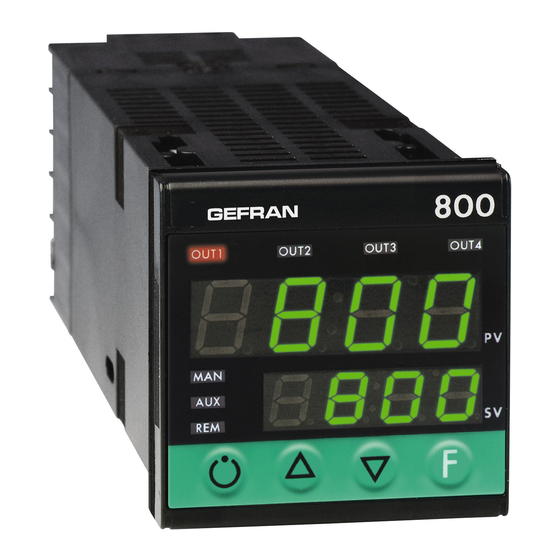
800
CONTROLLER
70
45
45
!
For correct and safe
installation, follow the
instructions and observe
the warnings contained in
this manual.
USER'S MANUAL
SOFTWARE VERSION 3.2x
code 80225E / Ed. 06- 04-2013
2 • TECHNICAL SPECIFICATIONS
Display
Keys
Accuracy
Main input
Thermocouples
Cold junction error
RTD type (scale configurable within indicated
range, with or without decimal point)
PTC type (on request)
Max line resistance for RTD
Safety
°C / °F selection
70
Linear scale ranges
Controls
pb / dt / di
Action
Cycle time
Main output type
Softstart
Maximum power limit heat / cool
Fault power setting
Automatic blanking
Configurable alarms
Alarm masking
Type of relay contact
Logic output for static relays
Remote setpoint or ammeter input
(options)
CT scale range
Transmitter power supply (optional)
Analogue retransmission signal (optional)
Logic inputs (optional)
Serial interface (optional)
Baud rate
Protocol
Power supply (switching type)
Faceplate protection
Working / Storage temperature range
Relative humidity
Environmental conditions of use
Installation
Weight
EMC conformity has been tested with the following connections
FUNCTION
Power supply cable
Relay output cable
Digital communication cable
C.T. connection cable
TC input
Pt100 input
2 x 4 digits, green, height 10 and 7mm
4 mechanical keys (Man/Auto, INC, DEC, F)
0.2% full scale at 25°C room temperature
TC, RTD (Pt100 - JPT100), PTC,
50mV, Ri ≥ 1MΩ, 10V, Ri ≥ 10KΩ, 20mA, Ri = 50W
IEC 584-1
(J, K, R, S, T, B, E, N, Ni-Ni18Mo, L NiCr-CuNi)
0,1° / °C
DIN 43760 (Pt100, JPT100)
990Ω, 25°C
20Ω
detection of short-circuit or opening of probes, LBA
alarm, HB alarm
configurable from faceplate
-1999 to 9999 with configurable decimal point position
PID, Self-tuning, on-off
0.0 ... 999.9% / 0.00 ... 99.99min / 0.00 ... 99.99min
Heat / Cool
on / off, pwm
0.1 ... 200 sec
Relay, Logic, Continuous (optional)
0.0 ... 500.0 min
0.0 ... 100.0 %
-100.0 ... 100.0 %
Optional exclusion, displays PV value
3 configurable alarms type: max, min, symmetrical,
absolute or relative, LBA, HB
- exclusion during warm up
- latching reset from faceplate or external contact
NO (NC), 5A, 250V, cosj = 1
11Vdc, Rout = 220Ω (6V/20mA)
0 ... 10V, 2 ... 10V, Ri ≥ 1MΩ
0 ... 20mA, 4 ... 20mA, Ri = 5Ω
Potentiometer > 500Ω,
CT 50mAac, 50/60Hz, Ri = 1.5Ω,
isolation 1500V
configurable from 0, ... , 100.0A
filtered 10 / 24Vdc, max 30mA
short-circuit protection, isolation 1500V
10V / 20mA, isolation 1500V
24V NPN, 4.5mA; 24V PNP, 3.6mA isolation
1500V
CL; RS422/485; RS232; isolation 1500V
1200 ... 19200
GEFRAN / MODBUS
(std) 100 ... 240Vac/dc ±10%; 50/60Hz, 12VA max
(opt.) 20...27Vac/dc ±10%; 50/60Hz, 12VA max
IP65
0...50°C / -20...70°C
20 ... 85% non-condensing
for internal use only, altitude up to 2000m
Panel, plug-in from front
210g for the complete version
CABLE TYPE
LENGTH
1 mm
1 m
2
1 mm
3,5 m
2
0,35 mm
3,5 m
2
1,5 mm
3,5 m
2
0,8 mm
compensated
5 m
2
1 mm
3 m
2
1
Advertisement
Table of Contents

Subscribe to Our Youtube Channel
Related Manuals for gefran 800


Summary of Contents for gefran 800
- Page 1 Digital communication cable 0,35 mm 3,5 m SERVICE: GEFRAN has a service department. The warranty excludes defects caused C.T. connection cable 1,5 mm 3,5 m by any use not conforming to these instructions.
- Page 2 3 • DESCRIPTION OF FACEPLATE Function indicators Indication of output states OUT 1 (Main); OUT 2 (AL 1); Indicates modes of operation OUT 3 (AL 2); OUT 4 (HB) MAN = OFF (Automatic control) MAN = ON (Manual control) PV Display: Indication of process variable AUX = OFF (IN1 = OFF - local Setpoint 1) Error Indication: LO, HI, Sbr, Err AUX = ON (IN1 = ON –...
- Page 3 Device structure: identification of boards CPU BOARD DISPLAY BOARD POWER BOARD W BOARD SERIAL BOARD 5 • PROGRAMMING and CONFIGURATION INFO LEVEL 1 MENU Information display Press for approx. dAtA Custom menu P.V. / S.V. Process variable (PV display) 2 sec Work Setpoint (SV display) or control output value with regulator in manual Control parameters...
- Page 4 • InFo Display Information INFO display Software prot Serial protection code (ode communication code 0 No Error Self er. n r 1 Lo diagnostic Software updt 2 Hi error version 3 ERR code 4 SBR • CFG Control parameters S.tun Continuous Self-tuning Softstart Minimum power limit for...
- Page 5 485 / 232 2400 485 / 232 4800 485 / 232 SEr.P Serial protocol Serial interface 9600 485 / 232 ser. p CENCAL GEFRAN protocol CENCAL, 19200 485 / 232 MODBUS RTU MODBUS _ PAr Parity No parity Parity selection Even •...
- Page 6 Digital filter on aux input filt flt. 2 Digital filter on main input 0.0 ... 20.0 sec (if enabled) 0.0 ... 20.0 sec [see “hrd.1” on Hrd] Minimum range for aux fild lo. 5 2 Digital filter on display Min…max input range 0 ...
- Page 7 Out W1 an. o . i Out 1 rl. o . 1 Assignment of signal or reference value: PV, SP, Allocation of SP-PROG, DEV+, DEV-, IN.AUX, HEAT, COOL, reference signal: AL1, AL2, AL3, serial line value HEAT, COOL, AL1, AL2, AL3, An.o.1, An.o.2 rL.o.1, rL.o.2, rL.o.3, rL.o.4 repetition of...
- Page 8 • Hrd SEnS Probe type for main input Selection of Thermocouple (TC) Hardware configuration sens probe type for Resistance Thermometer (RTD) main input Thermistor (PTC) hrd.1 Logic Logic Serial Voltage 0...50mV / 10...50mV analogue input 1 input 2 interface Current 0...20mA / 4...20mA Auxiliary input hrd.
- Page 9 Function of “MAN” LEDs: M/A, L/R, ATUN, IN1, IN2 led. 1 repetition, event programmer, serial port enabled, errors present LEd.1 (MAN), LEd.2 (AUX), LEd.3 (REM) LEd.x Function none led. 2 MAN/AUTO (ON in manual, OFF in auto) LOC/REM (ON in remote, OFF in local) self-tuning enabled autotuning enabled IN1 repetition...
- Page 10 6 • TIMER + 2 SET POINT, TIMER FUNCTION The timer functionality is enabled in Hrd configuration in hrd.1 parameter setting the code +16 or +48 to activate the selection of two set points. In the case of enabling, parameters _S.S.t. (start/stop timer) and _ _r.t. (reset timer) define the functioning modality. The intervention threshold of the tS timer can be set at level 1 of programming with bottom of scale 9999 sec.
- Page 11 8 • ALARMS Normal absolute alarm Symmetrical absolute alarm AL1 + [ Hyst1 ] AL2 + Hyst2 AL1 + Hyst1 AL1 - [ Hyst1 ] time time alarm 1 Lo alarm Hi alarm alarm 2 For AL1 = reverse absolute alarm (low) with positive Hyst1, AL1 t = 1 For AL1 = symmetrical reverse absolute alarm with Hyst1, AL1 t = 5 (*) = OFF if disabled on power-up For AL1 = symmetrical direct absolute alarm with Hyst1, AL1 t = 4...
- Page 12 If the Integral Time value is too long (Weak integral action), deviation between the controlled variable and the setpoint may persist. Contact GEFRAN for more information on control actions. 11 • MANUAL TUNING A) Enter the setpoint at its working value.
- Page 13 13 • SELF-TUNING The function works for single output systems (heating or cooling). The self-tuning action calculates optimum control parameter values during process startup. The variable (for example, temperature) must be that assumed at zero power (room temperature). The controller supplies maximum power until an intermediate value between starting value and setpoint is reached, after which it zeros power. PID parameters are calculated by measuring overshoot and the time needed to reach peak.
- Page 14 LoS = 0, HiS = 400, oFt = 0 Reference point on real curve: A1 = St00 = 50, B1 = St01 = 350 (B1-A1 = 300, greater than 25% of 800) Corresponding points on corrected curve: A2 = St02 = 120, B2 = St03 = 220...
- Page 15 VAC. Resistors must be at least 2W); fit a 1N4007 diode in parallel with the coil of inductive loads that operate in DC. GEFRAN spa will not be held liable for any injury to persons and/or damage to property deriving from tampering, from any incorrect or erroneous use, or from any use not conforming to the device specifications.
- Page 16 800 / 800P / 800V APPENDIX PONTICELLI PER CONFIGURAZIONE PONTS ÉTAIN POUR CONFIGURATION JUMPERS FOR CONFIGURATION PUENTES PARA CONFIGURACIÓN BRÜCKEN FÜR KONFIGURATION PONTES PARA CONFIGURAÇÃO Struttura dello strumento: identificazione schede Device structure: identification of boards Aufbau des Instruments: Leiterplatten Structure de l’appareil: identification des cartes Estructura del instrumento: identificación fichas...
- Page 17 DESCRIPTION PONTS ÉTAIN DESCRIPCIÓN PUENTES DESCRIÇÃO PONTES Validation configuration S3 (fermée) Habilitación configuración S3 (cerrado) Habilitação da configuração S3 (fechado) Validation étalonnage S4 (fermée) Habilitación calibración S4 (cerrado) Habilitação da calibração S4 (fechado) OUT3 relais désexcité mise en marche S9 (fermée) OUT3 relé...
- Page 18 (45090)1 SCHEDA POWER 10/30 POWER BOARD 10/30 NETZTEIL-KARTE 10/30 CARTE ALIMENTATION 10/30 FICHA ALIMENTACIÓN 10/30 PLACA DE ALIMENTAÇÃO 10/30 DESCRIZIONE PONTICELLI DESCRIPTION JUMPERS BESCHREIBUNG BRÜCKEN DESCRIPTION PONTS ÉTAIN DESCRIPCIÓN PUENTES DESCRIÇÃO PONTES OUT2 relè diseccitato power ON S1 (posizione A) OUT2 relay OFF at power ON S1 (position A) Ausgang 2;...
- Page 19 (44949)3 S24A S24B SCHEDA OUT W / INGRESSI DIGITALI OUT W BOARD / DIGITAL INPUTS ANALOG AUSGÄNGE / DIGITALE EINGÄNGE CARTE OUT W / ENTREES NUMERIQUES FICHA OUT W / ENTRADAS DIGITALES PLACA OUT W / ENTRADAS DIGITAIS DESCRIZIONE PONTICELLI DESCRIPTION JUMPERS BESCHREIBUNG...
- Page 20 S2333 USCITA ANALOGICA W1 (DIP SWITCHES S2333) ANALOGUE OUTPUT W1 (DIP SWITCHES S2333) ANALOGER AUSGANG W1 (DIP SWITCHES S2333) SORTIE ANALOGIQUE W1 (DIP SWITCHES S2333) SALIDA ANALÓGICA W1 (DIP SWITCHES S2333) SAÍDA ANALÓGICA W1 (DIP SWITCHES S2333) TIPO USCITA SELEZIONE ON SELEZIONE OFF OUTPUT TYPE SELECTION ON...
- Page 21 (44950)6 S3 S4 S2 S1 SCHEDA SERIALE / SPR SERIAL BOARD KARTE FÜR DIE SERIELLE ÜBERTRAGUNG CARTE SÉRIE FICHA SERIE PLACA DE COMUNICAÇÃO DIGITAL INGRESSO SPR PONTICELLI (chiusi) PONTICELLI (aperti) SPR INPUT JUMPERS (closed) JUMPERS (open) SPR EINGANG BRÜCKEN (geschlossen) BRÜCKEN (geöffnet) ENTREE SPR PONTS ÉTAIN (fermées)
Need help?
Do you have a question about the 800 and is the answer not in the manual?
Questions and answers