Table of Contents
Advertisement
Advertisement
Table of Contents

Subscribe to Our Youtube Channel
Related Manuals for gefran SIEIDrive AVy Series


Summary of Contents for gefran SIEIDrive AVy Series
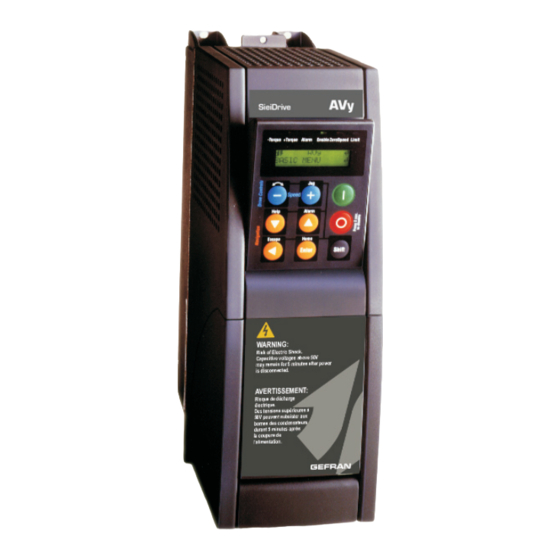
- Page 1 Vector AC Drives Quick start up guide Specification and installation...
- Page 2 Keep the manual in a safe place and available to engineering and installation per- sonnel during the product functioning period. Gefran S.p.A has the right to modify products, data and dimensions without notice. The data can only be used for the product description and they can not be under- stood as legally stated properties.
-
Page 3: Table Of Contents
Table of Contents Safety symbol legend ........................... 8 0. SAFETY PRECAUTIONS - PRECAUTIONS DE SECURITÉ ........9 1. QUICK START UP GUIDE ..................13 1.1. FUNCTIONAL CONNECTION DIAGRAM .................. 13 1.2. OVERVIEW ..........................14 1.3. CONTROL TERMINALS ......................15 1.3.1 Maximum cable cross section for regulator terminals ............16 1.4. - Page 4 3.3. STANDARD SPECIFICATIONS ....................43 3.3.1. Permissible environmental conditions ................43 Table 3.3.1.1: Environmental specification ....................43 Disposal of the Device ........................44 3.3.2. AC Input/Output Connection ................... 44 Table 3.3.2.1:AC Input/Output specifications .................... 45 3.3.3. AC Input current ......................46 3.3.4.
- Page 5 Figure 5.2.1.5: PV33-5-.. power card (sizes 6750 to 71320) ..............65 Figure 5.2.1.6: PV33-6-.. power card (sizes 81600 to 82000) ..............65 5.2.2. Terminal Assignment on Power section / Cable Cross-Section ......... 66 Figure 5.2.2.1: Power Terminals connection ..................... 66 Table 5.2.2.1: Maximum cable cross section for power terminals ............
- Page 6 Table 5.8.2.2: Braking thresholds for different Mains ................85 Table 5.8.2.3: Technical data of the internal braking units ................ 85 5.8.3. Calculation of generic external braking resistor to be combined with the internal braking unit with an approximate method ....................86 Figure 5.8.3.1: Power Resistor Overload Factor ..................
- Page 7 Links function ........................... 124 Test Generator ..........................125 Alarm mapping ..........................126 8. PARAMETERS LIST .................... 127 EMC DIRECTIVE ...................... 154...
-
Page 8: Safety Symbol Legend
Safety symbol legend Commands attention to an operating procedure, practice, condition, or statement which, ARNING if not strictly observed, could result in personai injury or death. Commands attention to an operating procedure, practice, condition, or statement which, AUTION if not strictly observed, could result in damage or destruction of equipment. The seriousness of the injuries and of the damages which could be caused by the non- observance of such indications, depends on the different conditions. -
Page 9: Safety Precautions - Precautions De Securité
0. SAFETY PRECAUTIONS - PRECAUTIONS DE SECURITÉ TTENTION! According to the EEC standards the AVy and accessories provoquer des incendies ou des explosions. Les drives must be used only after checking that the machine has been doivent être installés loin des zônes dangeureuses, et produced using those safety devices required by the 89/ équipés de moteurs appropriés. - Page 10 WARNING! - POWER SUPPLY AND GROUNDING / ATTENTION ! ALIMENTATION PUISSANCE ET MISE À LA TERRE In case of a three phase supply not symmetrical to ground, Si le réseau n'est pas équilibré par rapport à la terre et an insulation loss of one of the devices connected to the qu'il n'y a pas de transformateur raingle/étoile, une same network can cause functional problem to the drive, mauvaise isolation d'un appareil électrique connecté...
- Page 11 CAUTION / PRECAUTION: Si la Fault Alarm du drive est activée, consulter la section Do not connect power supply voltage that exceeds the du manuel concernant les défauts et après avoir corrigé standard specification voltage fluctuation permissible. If l’erreur, reprendre l’opération. Ne pas réiniliatiser l’alarme excessive voltage is applied to the Drive, damage to the automatiquement par une séquence externe, etc….
- Page 12 be carried out by qualified personnel, who are capots. Si la plaque frontale doit être enlevée also responsible for the provision of a suitable pour un fonctionnement avec la température ground connection and a protected power de l’environnement plus haute que 40°C, supply feeder in accordance with the local and l’utilisateur doit s’assurer, par des moyens national regulations.
-
Page 13: Quick Start Up Guide
1. QUICK START UP GUIDE 1.1. FUNCTIONAL CONNECTION DIAGRAM AC Mains AC Drive Cabinet Mounting panel Contactor AC fuses Power Supply Mains choke U1 V1 W1 U2 V2 W2 PE2 PE1 EMI filter Motor cable Ground terminals Encoder cable AC Motor PE1 is the drive safety ground. -
Page 14: Overview
1.2. OVERVIEW Quotes: Quote marks are put around words which This guide assumes a standard start up using the will be seen in the display window of the keypad. keypad for a drive and motor that is to be run in either sensorless vector or flux vector (with digital or sinusoidal encoder for feedback) mode. -
Page 15: Control Terminals
1.3. CONTROL TERMINALS Strip X1 Function Programmable/configurable analog differential input. Signal: terminal 1. Analog input 1 Reference point: terminal 2. Default setting: Ramp ref 1 ±10V Programmable/configurable analog differential input. Signal: terminal 3. 0.25mA Analog input 2 Reference point: terminal 4. Default setting: none (20mA when current ref Programmable/configurable analog differential input. -
Page 16: Maximum Cable Cross Section For Regulator Terminals
1.3.1 Maximum cable cross section for regulator terminals Maximum Permissible Cable Cross-Section Tightening Terminals torque flexible multi-core [Nm] 1 ... 79 0.14 ... 1.5 0.14 ... 1.5 28 ... 16 80 ... 85 0.14 ... 1.5 0.14 ... 1.5 28 ... 16 Ai4090 NOTE: Terminal board points are intended for 1 wire/point. -
Page 17: Encoder Terminals (Xe Connector)
1.5 ENCODER TERMINALS (XE CONNECTOR) Designation Function Max. voltage Max. current Channel B- 5 V digital or 10 mA digital or PIN 1 ENC B- Incremental encoder signal B negative 1 V pp analog 8.3 mA analog +8V Encoder supply voltage +8 V 200 mA PIN 2... -
Page 18: Jumpers Setting
1.5.2 Jumpers setting Encoder / Jumpers setting OFF OFF OFF OFF OFF OFF ON (*) ai3150 DE: 5V digital incremental encoder with A / A, B / B, C / C SE: 5V sinusoidal incremental encoder with A / A, B / B, C / C (*) If the encoder is not provided with the zero channel S17=OFF 1.5.3 Maximum cable length for encoder terminals Cable section [mm... -
Page 19: List Of Jumpers And Dip-Switch
1.6. LIST OF JUMPERS AND DIP-SWITCH Designation Function Factory setting S5 - S6 Terminating resistor for the serial interface RS485 ON (*) ON= Termination resistor IN OFF= No termination resistor Adaptation to the input signal of analog input 1 (terminals 1 and 2) ON=0...20 mA / 4...20 mA OFF=0...10 V / -10...+10 V Adaptation to the input signal of analog input 2 (terminals 3 and 4) -
Page 20: Keyboard Operation
1.7. KEYBOARD OPERATION The keypad is made of a LCD display with two 16-digit lines, seven LEDs and nine function keys. It is used: to control the drive, when this kind of use has been programmed (Main commands=DIGITAL) to display the speed, voltage, diagnostics etc. during the operation to set the parameters -Torque +Torque Alarm Enable ZeroSpeed Limit -Torque... - Page 21 Control Text reference Function buttons START button commands the Drive to the Enable (Stop control function ON) and Run state (Main commands = DIGITAL) [START] When Main commands is set as TERMINALS the button is not active STOP button commands to stop the Drive from the Run state when Main commands is set as DIGITAL [STOP] (Pressing this button for 2 sec, the drive will be disabled).
-
Page 22: Moving Inside A Menu
1.7.2 Moving inside a menu AVy -HGB... -
Page 23: Pre Power Checks
1.8. PRE POWER CHECKS The following should be checked before switching ON the Drive: Grounds / Grounding · Verify ground connections Drive to motor · Verify AC Input, AC Output and control wiring aren’t grounded Connections · Verify AC Input (U1/L1, V1/L2, W1/L3), AC Output (U2/T1, V2/T2, W2/T3), DC link connection with an optional external braking unit (C,D), Motor thermistor (78,79), OK Relay (80,82 n.o), Relay2 (83,85 n.o.) and regulation board (1..46, XS, XE) connections 12 ENABLE DRIVE (close to activate) -
Page 24: Quick Tuning
1.9. QUICK TUNING 5. Load Default Motor Values: 1. After a complete check of wiring and input voltage levels and then turn the power on: · Press [Left arrow] until back to “BASIC MENU” and then [Down arrow] to “DRIVE ·Verify the following voltages must be present: PARAMETER”, then [Enter], then [Down Terminal 7, +10V to terminal 9 (on regulation... - Page 25 · Press [Down arrow] to “Take motor par” and 10. Prepare for Self Tune: [Enter] and set all the motor parameters. If, when The keypad will be used for this purpose but the you do this, a message saying “Over-range I/O needs to be connected properly so the error XXX”...
- Page 26 to terminal 12. Press [Enter], “start part 2a ?” - Set the current limit (BASIC MENU\ T or “start part 2b ?” then [Enter] and see “measure Current lim +/-) to a value compatible with sat 2a (or b)” will appear and the motor shaft the motor size and load.
-
Page 27: Motor Potentiometer
Motor Potentiometer 1.9.1 Control buttons Sequencing Display Press START button to command the Drive to the Enable and Run state Press STOP button commands to stop the Drive from the Run state Motor pot oper Press to display the current reference value and to increase the reference value and accelerate the drive. -
Page 28: Optional Things
1.10 OPTIONAL THINGS Encoder verification: Set the Drive in V/f mode and analog output 1 is set to maximum speed then max run the motor, enable and start the drive and set an speed will be scaled 10 Vdc (maximum output analog reference. -
Page 29: Quick Tuning Guide For Factory Configured (Or Pre-Configured) Drives
1.11 QUICK TUNING GUIDE FOR FACTORY CONFIGURED (OR PRE- CONFIGURED) DRIVES When the drive configuration has already been set and you are simply tuning a motor which has not been tuned, you can ignore most of the preceding procedure, since it has already been done, but unless you are certain, it is recommended that you go through the steps anyway, just to verify that the data shown in the various locations indicated is OK. -
Page 30: Troubleshooting
1.12 TROUBLESHOOTING Overflow list CODE CAUSES 10 ; 54 The ratio between the Encoder 1 pulses[416] and the number of motor poles pair must be higher than 128 3 ; 4 The Stator resistance [436] value is too high. The motor is not compatible with the drive size used. -
Page 31: List Of Self Tune Error Messages
LIST OF SELF TUNE ERROR MESSAGES - Generic messages Description Note Provide enable input by setting terminal 12 high. “Drive disabled”: “Take values part 1” or “Take values part 2a” or “Take values part 2b”or “Take “Not ready”: values part 3” can not be executed because the measurement has not been completed correctly. -
Page 32: Failure Alarms In The Keypad Display
Failure alarms in the keypad display FAILURE ALARM POSSIBLE CAUSES Check the cable connection between regulator board and keypad. Blank display on the keypad The braking duty cycle is out of the allowed range BU overload Failure in the Bus connection (only with interface Bus option card) Bus loss Check the Bus connection EMC compatibility problem, check wiring. - Page 33 (For sizes from 22kW ... and higher). Temperature of the cooling air too high. Intake air ot Failure of device fan(s). Cooling opening obstructed. An unused interrupt has occurred Interrupt error Switch off device and restart If you are unsuccessful: probably an internal fault. Contact your service office. (For sizes from 0.75 to 15 kW).
-
Page 34: Other Faults
- With the Drive disabled turn the motor clockwise (viewed from the front of the shaft). The value indicated must be positive. - If the indicated value does not change or random values are shown, check the power supply and the cabling of the encoder. - If the indicated value is negative, reverse the encoder connections. - Page 35 - T current lim reduction selected via Torque reduct The entered value for the number of encoder pulses is too high. Remedy: check the parameters concerned (encoder 1 pulses) and set correct value. A correction value reduces the main reference value. Remedy: check the configuration With operation via the terminal strip: Speed base value parameter too low Motor accelerates immediately to maximum speed Reference value set via terminals: Check whether the value varies from min.
- Page 36 correctly set - Check the value for the current limitation - The value for Magnetizing curr and/or Rotor resistance parameters is not correct. Optimize the tuning as described in the instruction book. The speed during acceleration with maximum current is not linear Reduce the Speed I and Speed P proportionally.
-
Page 37: Function And Feature (Overview)
2. FUNCTION AND FEATURE (OVERVIEW) Motor potentiometer function (Increase/Decrease The AVy is a field-oriented vector Drive with excel- speed by command) lent speed control properties and a high torque. Jog operation Available control modes are: 8 internal speed reference values (Preset speed) Field oriented with speed sensor 4 internal ramps Field oriented without speed sensor (Sensorless... - Page 38 Ch.2 ——— Function and feature (overview) ———...
-
Page 39: Inspection Procedure, Component Identification And Standard Specification
3. INSPECTION PROCEDURE, COMPONENT IDENTIFICATION AND STANDARD SPECIFICATION 3.1. UPON DELIVERY INSPECTION PROCEDURES 3.1.1. General A high degree of care is taken in packing the AVy Drives and preparing them for delivery. They should only be transported with suitable transport equipment (see weight data). Observe the instructions printed on the packaging. -
Page 40: Nameplate
3.1.3. Nameplate Check that all the data stated in the nameplate enclosed to the inverter correspond to what has been ordered. Figure 3.1.3.1: Identification nameplate Type AVy1030-XXX S/N 9862330 Main Power In : 480 Vac 8.9 A 50/60Hz 3Phase Main Power Out : 0-480Vac 7.5A 0-400Hz... -
Page 41: Component Identification
3.2. COMPONENT IDENTIFICATION An AVy Drive converts the constant voltage and frequency of a three-phase power supply into a direct voltage and then converts this direct voltage into a new three-phase power supply with a variable voltage and frequency. This variable three-phase power supply can be used for the infinitely variable adjustment of the speed of three-phase asynchronous motors. -
Page 42: Figure 3.2.2: Drive View & Components
Figure 3.2.2: Drive view & components Keypad Cover Cable entry plate Top cover Regulation card Power card Cooling fan IGBT Bridge Dissipator Cooling fan (for type 1015 and higher) Ch.3 AVy - HGB... -
Page 43: Standard Specifications
3.3. STANDARD SPECIFICATIONS 3.3.1. Permissible environmental conditions Table 3.3.1.1: Environmental specification 0 … +40; +40…+50 with derating [°C] Ambient temperature 32 … +104; +104…+122 with derating [°F] Pollution degree 2 or better (free from direct sunligth, vibration, dust, corrosive or inflammable gases, fog, vapour oil and dripped water, avoid saline Installation location environment) IP20... -
Page 44: Disposal Of The Device
AVy...-DC versions In this version, the drive must be powered by a rectified DC supply of 600 Vdc. The use of Gefran SM32 series power supplies is recommended for this, available with an output current from 185 to 2000A. From size AVy4185, insertion of an AC mains inductance on the power supply input of the power supply unit is compulsory (for the type of inductance, consult the manual of the power supply unit), see figure 5.5.1.2. -
Page 45: Table 3.3.2.1:Ac Input/Output Specifications
Table 3.3.2.1:AC Input/Output specifications Ch.3 ——— Inspection procedure, component identification and standard specification ———... -
Page 46: Ac Input Current
3.3.3. AC Input current The Input current of the Drive depends on the operating state and the service conditions of the connected motor, and the use of input reactors. The table 3.3.2.1 shows the values corresponding to rated continuous service (IEC 146 class 1), keeping into account typical output power factor for each size 3.3.4. -
Page 47: Table 3.3.3.1: Nominal Drive Current
Table 3.3.3.1: Nominal Drive Current Ch.3 ——— Inspection procedure, component identification and standard specification ———... -
Page 48: Open-Loop And Closed-Loop Control Section
3.3.5. Open-Loop and Closed-Loop Control Section Enable inputs 0 / 15...30 V 3.2...6.4 mA (5 mA @ 24 V) Analog inputs Selectable 0... ± 10 V 0.25 mA max 0...20 mA 10 V max 4...20 mA 10 V max Max common mode voltage: 0...± 10 V Analog outputs 0...±... -
Page 49: Accuracy
3.3.6. Accuracy Output frequency: £ 50 ppm/°C typical temperature dependent stability error [°C] 0.001 Hz at 50 Hz resolution [Hz] 0.005 Hz at 300 Hz ± 10V, terminals 7 and 8 Internal reference value voltage: 100 ppm/°C typical - temperature dependent stability error [°C] Reference values: 16 bit or 15 bit + sign... - Page 50 Ch.3 AVy - HGB...
-
Page 51: Installation Guidelines
4. INSTALLATION GUIDELINES 4.1. MECHANICAL SPECIFICATION Figure 4.1.1: Drive dimensions (sizes 1007 ... 3150) Figure 4.1.2: Mounting methods (sizes 1007 ... 3150) E2 E4 Mounting with external dissipator (E) Mounting wall (D) Table 4.1.1: Drive dimensions and Weights (sizes 1007 ... 3150) Type 1007 1015... -
Page 52: Figure 4.1.3: Drive Dimensions (Sizes 4185 ... 82000)
Figure 4.1.3: Drive dimensions (sizes 4185 ... 82000) Figure 4.1.4: Mounting methods (sizes 4185 ... 82000) Mounting wall (D) Table 4.1.2: Drive dimensions and Weights (sizes 4185 ... 82000) Type 4185 4220 4300 4370 5450 5550 6750 7900 71100 71320 81600 82000 Drive dimensions:... -
Page 53: Watts Loss, Heat Dissipation, Internal Fans And Minimum Cabinet Opening Suggested For The Cooling
Figure 4.1.5: Keypad positioning To allow a confortable viewing angle, the keypad can be oriented on three different positions. 4.2. WATTS LOSS, HEAT DISSIPATION, INTERNAL FANS AND MINIMUM CABINET OPENING SUGGESTED FOR THE COOLING The heat dissipation of the Drives depends on the operating state of the connected motor. The table below shows values that refer to operation at default switching frequency (see section 3.3.4, “AC Output”), Tamb <40°C, typ. -
Page 54: Cooling Fans Power Supply
4.2.1 Cooling fans power supply Power supply (+24VAC) for these fans are provided from the in- Sizes 1007 to 5550 ternal drive power supply unit. Power supply for these fans have to be provided as follow: Sizes 6750 to 82000 - AVy6750: 0.8A@115V/60Hz, 0.45A@230V / 50Hz - AVy7900 ... -
Page 55: Installation Mounting Clearance
4.3. INSTALLATION MOUNTING CLEARANCE The dimensions and weights specifed in this manual should be taken into consideration when the device is mounted. The technical equipment required (carriage or crane for large weights) should be used. Improper handling and the use of unsuitable tools may cause damage. -
Page 56: Motors And Encoders
4.4. MOTORS AND ENCODERS The AVy Drives designed for the field oriented regulation of standard three-phase induction AC motors. A sinusoidal encoder or digital encoder can be used for feedback in proportion to speed. 4.4.1. Motors The electrical and mechanical data of standard three-phase motors refers to a particular operating range. The following points should be noted when these motors are connected to an AC Drive: Is it possible to use standard induction motors? With the AVy Drives it is possible to use standard induction motors. -
Page 57: Encoder
Temperature-dependent contacts in the motor winding Temperature-dependent contacts “Klixon” type can disconnect the drive via the external control or can be reported as an external fault on the frequency inverter (terminal 15). They can also be connected to the terminals 78 and 79 in order to have a specific error signal. In this case connect the existing 1 Kohm resistor in series to the wiring, note that one side of it must be connected directly to terminal 79. -
Page 58: Table 4.4.2.2: Encoders Setting Via S11...S23 Jumpers
Table 4.4.2.2: Encoders setting via S11...S23 jumpers Encoder / Jumpers setting OFF OFF OFF OFF OFF OFF ON (*) ai3150 The jumper S17 selects the inhibition or the enabling of the channel C pulses reading. It has to be correctly selected in order to detect appropriately the encoder loss alarm. - Page 59 Requirements: Sinusoidal encoders (XE connector on Regulation card) max. frequency 80 KHz ( select the appropriate number of pulses depending on required max. speed ) Number of pulses per revolution min 600, max 9999 Channels two-channel, differential Power supply + 5 V (Internal supply) * Load capacity >...
-
Page 60: Table 4.4.2.4: Assignment Of The High Density Xe Connector For A Sinusoidal Or A Digital Encoder
Table 4.4.2.4: Assignment of the high density XE connector for a sinusoidal or a digital encoder Designation Function Max. voltage Max. current Channel B- 5 V digital or 10 mA digital or PIN 1 ENC B- Incremental encoder signal B negative 1 V pp analog 8.3 mA analog +8V Encoder supply voltage... -
Page 61: Wiring Procedure
5. WIRING PROCEDURE 5.1. ACCESSING TO THE CONNECTORS 5.1.1 Removing the Covers Observe the safety instructions and warnings given in this manual. The devices can be opened without the use of force. Only use the tools specified. See figure 3.2.2 “Drive view & components” to identify the single part. Figure 5.1.1: Removing the covers (sizes 1007 to 3150) Sizes 1007 to 2075 The terminal cover and cable entry plate of the device must be removed in order to fit the electrical connec-... -
Page 62: Figure 5.1.2: Removing The Covers (Sizes 4220 To 82000)
Figure 5.1.2: Removing the covers (sizes 4220 to 82000) Sizes 4220 to 82000 The terminal cover of the device must be removed in order to fit the electrical connections: unscrew the two screw (2) and remove the cover (1) The top cover must be removed in order to mount the option card and change the internal jumper settings: unscrew the two screw (3) and remove the top cover by moving it as indicated on figure (4) In order to avoid damages of the device it is not allowed to transport it by handling on its TTENTION... -
Page 63: Power Section
5.2. POWER SECTION 5.2.1. PV33-.. Power card Figure 5.2.1.1: PV33-1-. power card (sizes 1007 to 1030) Figure 5.2.1.2: PV33-2-.. power card (sizes 2040 to 2075) Ch.5 —————— Wiring procedure ——————... -
Page 64: Figure 5.2.1.3: Pv33-3-.. Power Card (Sizes 3110 And 3150)
Figure 5.2.1.3: PV33-3-.. power card (sizes 3110 and 3150) Figure 5.2.1.4: PV33-4-.. power card (sizes 4220 to 5550) Ch.5 AVy - HGB... -
Page 65: Figure 5.2.1.5: Pv33-5-.. Power Card (Sizes 6750 To 71320)
Figure 5.2.1.5: PV33-5-.. power card (sizes 6750 to 71320) Figure 5.2.1.6: PV33-6-.. power card (sizes 81600 to 82000) Ch.5 —————— Wiring procedure ——————... -
Page 66: Terminal Assignment On Power Section / Cable Cross-Section
5.2.2. Terminal Assignment on Power section / Cable Cross-Section Figure 5.2.2.1: Power Terminals connection Function (max) - Sizes 1007 … 3150 Function (max)- Sizes 4220… 81600 U1/L1 U1/L1 AC mains voltage AC mains voltage 3Ph~ 3Ph~ V1/L2 V1/L2 (3x480 V +10% 3Ph, see table 3.3.2.1) (max 3x480 V +10%, see table 3.3.2.1) W1/L3... -
Page 67: Regulation Section
5.3. REGULATION SECTION 5.3.1 RV33 Regulation Card Figure 5.3.1.1: RV33-4 Regulation Card Switch & Jumpers FRONT SIDE BACK SIDE Table 5.3.1.1: LEDs & Test points on Regulation card Designation Color Function LED lit during the Hardware Reset green LED lit when the voltage +5V is present and at correct level green LED is lit when RS485 interface is supplied RS485... -
Page 68: Table 5.3.1.3: Jumpers On Regulation Card Rv33-3
Table 5.3.1.3: Jumpers on Regulation Card RV33-3 Designation Function Factory setting S5 - S6 Terminating resistor for the serial interface RS485 ON (*) ON= Termination resistor IN OFF= No termination resistor Adaptation to the input signal of analog input 1 (terminals 1 and 2) ON=0...20 mA / 4...20 mA OFF=0...10 V / -10...+10 V Adaptation to the input signal of analog input 2 (terminals 3 and 4) -
Page 69: Terminal Assignments On Regulation Section
5.3.2. Terminal Assignments on regulation section Table 5.3.2.1: Plug-in Terminal Strip Assignments Strip X1 Function Programmable/configurable analog differential input. Signal: terminal 1. Analog input 1 Reference point: terminal 2. Default setting: Ramp ref 1 ±10V Programmable/configurable analog differential input. Signal: terminal 3. 0.25mA Analog input 2 Reference point: terminal 4. -
Page 70: Table 5.3.2.3: Maximum Control Cable Lengths
+24Vdc voltage, which is used to externally supply the regulation card has to be stabilized AUTION and with a maximum ±10% tolerance. The maximum absorption is 1A. It is not suitable to power supply the regulation card only through a unique rectifier and capacitive filter. -
Page 71: Figure 5.3.1.2: Potentials Of The Control Section, Digital I/O Npn Connection
Figure 5.3.1.2: Potentials of the control section, Digital I/O NPN connection To Expansion Cards Analog input 1 Analog output 1 Analog input 2 Analog output 2 Analog input 3 +10V +24V Enable drive - 10V Start Fast stop Digital output 1 External fault Digital output 0 Digital input 1... -
Page 72: Serial Interface
5.4. SERIAL INTERFACE 5.4.1. Serial Interface Description The RS 485 serial interface enables data transfer via a loop made of two symmetrical, twisted conductors with a common shield. The maximum transmission distance is 1200 m (3936 feet) with a transfer rate of 38.4 KBaud. -
Page 73: Rs 485 Serial Interface Connector Description
only shielded cables are used power cables and control cables for contactors/relays are routed separately See the manual “SLINK3 Communication protocol” for more detail. 5.4.2. RS 485 Serial Interface Connector Description Table 5.4.2.1: Assignment of the plug XS connector for the RS 485 serial interface Designation Function Elec. -
Page 74: Standard Connection Diagram
5.5. STANDARD CONNECTION DIAGRAM 5.5.1. AVy Connections Figure 5.5.1.1:Control sequencing Stop ON / Start Mains contactor EMERGENCY-OFF ON / OFF t = 1 s Start / Stop Note: OK relay must be configured as “Drive healty” for this circuit (Factory configuration) The connection diagram reported in the picture 5.5.1.1 (Control sequencing) is valid only when the configuration of the sequency alarm Enable seq err is set as Ignore. -
Page 75: Figure 5.5.1.2: Typical Connection
Figure 5.5.1.2: Typical connection The circuit diagram is for the + 30 V standard configuration of the drive as delivered. Dig. Out.2 Dig. Out.1 EMC installation and wiring + 24V techniques are not shown. For this see appropriate chapter. 0 V24 The connection of option COM ID card is also shown... -
Page 76: Parallel Connection On The Ac (Input) And Dc (Intermediate Circuit) Side Of Several Inverters
5.5.2. Parallel Connection on the AC (Input) and DC (Intermediate Circuit) Side of Several Inverters Features and Limits: 1 The inverters used have to be all the same size. 2 AC line chokes (see chapter 5.7.1) have to be the same (provided by the same supplier). 3 The mains power supply has to be simultaneous for all inverters, i.e. -
Page 77: Circuit Protection
5.6. CIRCUIT PROTECTION 5.6.1. External fuses of the power section The inverter must be fused on the AC Input side. Use fast fuses only. Connections with three-phase inductance on AC input will improve the DC link capacitors life time. Table 5.6.1.1: External Fuse Types for AC input side F1 - Fuses type Connections without three-phase reactor Connections with three-phase reactor... -
Page 78: External Fuses Of The Power Section Dc Input Side
5.6.2. External fuses of the power section DC input side Use the following fuses when a SR-32 Line Regen converter is used (see SR-32 instruction book for other details). Table 5.6.2.1: External fuses type for DC input side Fuses type Drive type Europe Z14GR6... -
Page 79: Chokes / Filters
(for the type of inductance, consult the manual of the power supply unit), see figure 5.5.1.2. For the use of output sinusoidal filters, please contact the nearest Gefran office. 5.7.1. AC Input Chokes Table 5.7.1.1:3-Phase AC Input Chokes... -
Page 80: Interference Suppression Filters
In the Guide it is also indicated how to install the cabinet (connection of filter and mains reactors, cable shield, groundig, etc.) in order to make it EMC compliant according the EMC Directive 89/336/EEC. The document describes the present situation concerning the EMC standards and the compliance tests made on the Gefran drives. -
Page 81: Braking Units
5.8. BRAKING UNITS In oversynchronous or regenerative operation, the frequency-controlled three-phase motor feeds energy back to the DC link circuit via the Drive. This leads to an increase in the intermediate circuit voltage. Braking units (BU) are therefore used in order to prevent the DC voltage rising to an impermissible value. When used, these activate a braking resistor that is connected in parallel to the capacitors of the intermediate circuit. -
Page 82: External Braking Resistor
5.8.2 External braking resistor Recommended resistors for use with internal braking unit: Table 5.8.2.1: Lists and technical data of the external standard resistors for inverters AVy1007 to 5550 Inverter Resistor [kJ] Type Type [kW] [Ohm] 1007 RF 220 T 100R 0.22 1015 1022... - Page 83 Minimum cycle time in condition of limit operating cycle (braking power = P with typical triangular profile) =[s] The BU overload alarm occurs if the duty cycle exceeds the maximum data allowed in order to prevent possible damages to the resistor. Resistor model: Standard resistor data Example code: MRI/T900 68R...
-
Page 84: Figure 5.8.2.3:Generic Braking Cycle With Triangular Profile
Resistor model: MRI/T600 100R Nominal power P = 600 [W] Maximum energy E = 22 [kJ] Inverter mains supply = 460V From table 5.8.2.2: V =780V 24000 7.8[s] 6084 [W] 6084 It is necessary to consider the following relation: ≤ ≤ ≤ ≤ ≤ E If T verify: ≤... -
Page 85: Table 5.8.2.2: Braking Thresholds For Different Mains
The use of different braking resistors from those indicated on table 5.8.2.1, requires to take into considera- tion the meaning of following formulas: (time of braking at limit condition for cycle with triangular profile) BU ovld time [s] = E BU duty cycle % = (P ) x 100 Table 5.8.2.2: Braking thresholds for different Mains... -
Page 86: Calculation Of Generic External Braking Resistor To Be Combined With The Internal Braking Unit With An Approximate Method
5.8.3. Calculation of generic external braking resistor to be combined with the internal braking unit with an approximate method In order to calculate resistor values different from the one stated in the table 5.8.2.1 (having, for example, different values of turn-on threshold of the braking unit), the following remarks are valid: the peak power dissipated by the resistor is P [W] , where “V ”... -
Page 87: Buffering The Regulator Supply
5.9. BUFFERING THE REGULATOR SUPPLY The power supply of the control section is provided by a switched mode power supply unit (SMPS) from the DC Link circuit. The Drive is disabled as soon as the voltage of the DC Link circuit is below the threshold value (U ). - Page 88 When connecting the intermediate circuit terminals C and D the AC Input side must be protected with superfast semiconductor fuses! Formula for calculating the size of the external capacitors: SMPS Buff Buff fA018 [μF] = 400 V at U = 400 V SMPS Buff = 460 V at U...
-
Page 89: Avy Power Dip Ride Through Data And Restart Setup
5.10. AVy POWER DIP RIDE THROUGH DATA AND RESTART SETUP The AVy has a 3-phase full-wave rectifier feeding the DC link. If the DC link reaches the Undervoltage threshold for its voltage input (see tables 5.10.1, 5.10.2 and 5.10.3), the AVy will disable the Drive, and generate an undervoltage alarm. The undervoltage alarm can latch &... -
Page 90: Table 5.10.1: Drive Trip Times, 230-V Threshold
Full load losses Plfl are: 1 - h fA029 Maximum power supply drop out time (Buffer time/voltage failure buffer) of AVy is achieved by adding the maximum recommended capacitance to the DC bus. The following table show the maximum power supply drop out time for different Undervoltage thresholds and inverter sizes. -
Page 91: Table 5.10.2: Drive Trip Times, 400-V Threshold
Table 5.10.2: Drive Trip Times, 400-V Threshold Size Psmps buff buff 0.165 1007 0.165 1015 0.24 1022 0.24 1030 0.62 2040 0.62 2055 0.62 2075 1.12 1500 1500 3110 1.12 1500 1500 3150 1.54 1800 4500 4185 1.54 4220 1800 4500 1.88 2200... -
Page 92: Discharge Time Of The Dc-Link
5.11. DISCHARGE TIME OF THE DC-LINK Table 5.11.1: DC Link Discharge Times Type Time (seconds) Type Time (seconds) 1007 4300 1015 4370 5450 1022 1030 5550 2040 6750 7900 2055 2075 15.4 71100 21.6 3110 71320 28.7 81600 3150 4185 35,5 82000 avy4250... -
Page 93: Maintenance
6. MAINTENANCE 6.4. CUSTOMER SERVICE 6.1. CARE For customer service, please contact your Gefran The SieiDrive - AVy inverters must be installed office. according to the relevant installation regulations. They do not require any particular maintenance. They should not be cleaned with a wet or moist cloth. The power supply must be switched off before cleaning. -
Page 94: Block Diagram Legend
Block diagram legend Parameters Parameter name Ramp +/- delay Parameter value 100 ms Variables Variable name T current ref Variable value... -
Page 95: Block Diagram
7. BLOCK DIAGRAM Ch.7 ——— Block diagram ———... -
Page 96: Digital Inputs/Outputs & Mapping Standard And Option Cards
Ch.7 AVy -HGB... -
Page 97: Analog Inputs/Outputs & Mapping
Ch.7 ——— Block diagram ———... -
Page 98: Speed Reference Generation
Ch.7 AVy -HGB... -
Page 99: Speed / Torque Regulation
Ch.7 ——— Block diagram ———... -
Page 100: Ramp Reference Block
Ch.7 AVy -HGB... -
Page 101: Speed Regulator
Ch.7 ——— Block diagram ———... -
Page 102: Speed Regulator Pi Part
Ch.7 AVy -HGB... -
Page 103: Droop Compensation
Ch.7 ——— Block diagram ———... -
Page 104: Inertia / Loss Compensation
Ch.7 AVy -HGB... -
Page 105: Torque Current Regulator
Ch.7 ——— Block diagram ———... -
Page 106: Speed Feedback
Ch.7 AVy -HGB... -
Page 107: Motor Control
Ch.7 ——— Block diagram ———... -
Page 108: Motor Parameters
Ch.7 AVy -HGB... -
Page 109: Sensorless Parameters
Ch.7 ——— Block diagram ———... -
Page 110: V/Hz Functions
Ch.7 AVy -HGB... -
Page 111: Speed Threshold / Speed Control
Ch.7 ——— Block diagram ———... -
Page 112: Speed Adaptive And Speed Zero Logic
Ch.7 AVy -HGB... -
Page 113: Pid Function
Ch.7 ——— Block diagram ———... -
Page 114: Start And Stop Management
Ch.7 AVy -HGB... -
Page 115: Power Loss Stop Control
Ch.7 ——— Block diagram ———... -
Page 116: Jog Function
Ch.7 AVy -HGB... -
Page 117: Motor Potentiometer
Ch.7 ——— Block diagram ———... -
Page 118: Multi Speed
Ch.7 AVy -HGB... -
Page 119: Dual Motor Setup
Ch.7 ——— Block diagram ———... -
Page 120: Brake Unit Function
Ch.7 AVy -HGB... -
Page 121: Dc Braking Function
Ch.7 ——— Block diagram ———... -
Page 122: Dimension Factor / Face Value Factor
Ch.7 AVy -HGB... -
Page 123: Pad Parameters
output Digital output Digital output Analog output Analog Ch.7 ——— Block diagram ———... - Page 124 Ch.7 AVy -HGB...
- Page 125 Ch.7 ——— Block diagram ———...
- Page 126 Ch.7 AVy -HGB...
-
Page 127: Parameters List
8. PARAMETERS LIST Explanation of tables: Menu/submenu White text on black background Menu does not exist in the keypad White text on black background in brackets Function not accessible via keypad. The status of the correspond- Fields with gray background ing parameter is only displayed. - Page 128 “Opt2-A” (Low Priority) Parameter available via the APC Card asynchronous communica- “PDC” (High Priority) tion (see the APC Card user manual) and/or the Process Data Channel (PDC) of the Field bus. NOTE: When field Bus interface parameters whose range is [min=0;...
- Page 129 Value Access via Keyp. RS485/ Terminal Opt2-A Parameter No Format Factory BUS/ /PDC Opt2-M Drive ready Drive ready Drive not ready Quick stop No quick stop (1) Quick stop No Quick stop Fast stop No fast stop (1) Fast Stop No Fast Stop BASIC MENU Ö...
- Page 130 Value Access via Keyp. RS485/ Terminal Opt2-A Parameter No Format Factory BUS/ /PDC Opt2-M Dec delta time [s] 65535 T current lim + [%] T current lim - [%] Encoder 1 type Digital (1) Sinusoidal Digital Encoder 1 pulses Float* 9999 1024 Speed base value [FF]...
- Page 131 Value Access via Keyp. RS485/ Terminal Opt2-A Parameter No Format Factory BUS/ /PDC Opt2-M Dig input term 8 Dig input term 9 Dig input term 10 Dig input term 11 Dig input term 12 Dig input term 13 Dig input term 14 Dig input term 15 Dig input term 16 Dig output term...
- Page 132 Value Access via Keyp. RS485/ Terminal Opt2-A Parameter No Format Factory BUS/ /PDC Opt2-M Voltage I [%] Float 0.00 100.00 4.00 Voltage I Nw [%] Float 0.00 100.00 Take val part 2a 65535 DRIVE PARAMETER \ Motor Parameter \ Self-tuning \ Sel-tune 2b Start part 2b 65535 P1 flux model...
- Page 133 Value Access via Keyp. RS485/ Terminal Opt2-A Parameter No Format Factory BUS/ /PDC Opt2-M Ö Delay auto cap [ms] 10000 1000 Ö Delay retrying [ms] 10000 1000 DRIVE PARAMETER \ V/f control \ Energy save Ö Enable save eng Disabled (0) Enabled Disabled Ö...
- Page 134 Value Access via Keyp. RS485/ Terminal Opt2-A Parameter No Format Factory BUS/ /PDC Opt2-M RAMP \ Acceleration Ö Acc delta speed [FF] Ö Acc delta time [s] 65535 RAMP \ Deceleration Ö Dec delta speed [FF] Ö Dec delta time [s] 65535 RAMP \ Quick stop Ö...
- Page 135 Value Access via Keyp. RS485/ Terminal Opt2-A Parameter No Format Factory BUS/ /PDC Opt2-M SPEED REGULAT \ Spd zero logic Enable spd=0 I Disabled (0) Enabled Disabled Enable spd=0 R Disabled (0) Enabled Disabled Enable spd=0 P Disabled (0) Enabled Disabled Enable lck sls Disabled (0)
- Page 136 Value Access via Keyp. RS485/ Terminal Opt2-A Parameter No Format Factory BUS/ /PDC Opt2-M REG PARAMETERS \ Percent values \ Flux regulator Ö Flux P [%] Float 0.00 100.00 Ö Flux I [%] Float 0.00 100.00 REG PARAMETERS \ Percent values \ Voltage reg Ö...
- Page 137 Value Access via Keyp. RS485/ Terminal Opt2-A Parameter No Format Factory BUS/ /PDC Opt2-M Ö Enc1 supply vlt 1146 5.41 V (0) 5.41 V 5.68 V 5.91 V 6.18 V Ö Encoder 2 pulses Float* 9999 1024 Ö Encoder repeat 1054 Encoder 1 (1) Encoder 2...
- Page 138 Value Access via Keyp. RS485/ Terminal Opt2-A Parameter No Format Factory BUS/ /PDC Opt2-M CONFIGURATION \ Prog alarms \ Undervoltage Ö Latch ON (1) Ö OK relay open ON (1) Ö Restart time [ms] 65535 1000 Ö N of attempts CONFIGURATION \ Prog alarms \ Overvoltage Ö...
- Page 139 Value Access via Keyp. RS485/ Terminal Opt2-A Parameter No Format Factory BUS/ /PDC Opt2-M Quick stop Normal stop Curr lim stop Ö Latch ON (1) Ö Ok relay open ON (1) CONFIGURATION \ Prog alarms \ External fault Ö Activity Disable drive (2) Warning Disable drive...
- Page 140 Value Access via Keyp. RS485/ Terminal Opt2-A Parameter No Format Factory BUS/ /PDC Opt2-M Disable drive Quick stop Normal stop Curr lim stop Ö OK relay open ON (1) CONFIGURATION \ Prog alarms \ Enable seq err Ö Activity Disabled drive (2) Ignore Disable drive Ö...
- Page 141 Value Access via Keyp. RS485/ Terminal Opt2-A Parameter No Format Factory BUS/ /PDC Opt2-M Output voltage Voltage U Voltage V DC link voltage Analog input 1 Analog input 2 Analog input 3 Flux Active power Torque Rr adap output Pad 0 Pad 1 Pad 4 Pad 5...
- Page 142 Value Access via Keyp. RS485/ Terminal Opt2-A Parameter No Format Factory BUS/ /PDC Opt2-M Ö An in 1 target Assign. (0) Assigned Not assigned Ö Input 1 type ± 10 V (0) -10V ... + 10 V 0...20 mA, 0...10 V 4...20 mA Ö...
- Page 143 Value Access via Keyp. RS485/ Terminal Opt2-A Parameter No Format Factory BUS/ /PDC Opt2-M Drive ready Overld available Ramp + Ramp - Speed limited Undervoltage Overvoltage Heatsink sensor Overcurrent Overtemp motor External fault Failure supply Pad A bit Pad B bit Virt dig input Speed fbk loss Bus loss...
- Page 144 Value Access via Keyp. RS485/ Terminal Opt2-A Parameter No Format Factory BUS/ /PDC Opt2-M Torque reduct Ramp out = 0 Ramp in = 0 Freeze ramp Lock speed reg Lock speed I Auto capture Input 1 sign + Input 1 sign - Input 2 sign + Input 2 sign - Input 3 sign +...
- Page 145 Value Access via Keyp. RS485/ Terminal Opt2-A Parameter Format Factory BUS/ /PDC Opt2-M I/O CONFIG \ Encoder inputs Ö Select enc 1 1020 OFF (0) Speed ref 1 Speed ref 2 Ramp ref 1 Ramp ref 2 Ö Select enc 2 1021 OFF (0) Speed ref 1...
- Page 146 Value Access via Keyp. RS485/ Terminal Opt2-A Parameter No Format Factory BUS/ /PDC Opt2-M FUNCTIONS \ Motor pot Ö Enab motor pot Disabled (0) Enabled Disabled Ö Motor pot oper Motor pot sign Positive (1) Positive Negative Ö Motor pot reset 65535 ID H=reset Motor pot up...
- Page 147 Value Access via Keyp. RS485/ Terminal Opt2-A Parameter No Format Factory BUS/ /PDC Opt2-M FUNCTIONS \ Multi ramp fct \ Ramp 1 \ Acceleration 1 Ö Acc delta speed1 [FF] Ö Acc delta time 1 [s] 65535 Ö S acc t const 1 [ms] Float 3000 FUNCTIONS \ Multi ramp fct \ Ramp 1 \ Deceleration 1...
- Page 148 Value Access via Keyp. RS485/ Terminal Opt2-A Parameter No Format Factory BUS/ /PDC Opt2-M Ovld mot state Not ovrl (1) Overload Not overload FUNCTIONS \ Overload contr \ Ovld drv contr Ö I_sqrt_t_accum [%] Ovld Available Overload not possible Overload possible Overload 200% 1139 Overload not possible...
- Page 149 Value Access via Keyp. RS485/ Terminal Opt2-A Parameter No Format Factory BUS/ /PDC Opt2-M SPEC FUNCTIONS Ö Enable rr adap Disabled (0) Enabled Disabled Ö Save parameters 65535 Ö Load default 65535 Ö Life time [h.min] Float 0.00 65535.00 Ö Failure register Failure text Text...
- Page 150 Value Access via Keyp. RS485/ Terminal Opt2-A Parameter No Format Factory BUS/ /PDC Opt2-M Ö Input offset Float Ö Output offset Float Ö Input absolute OFF (0) SPEC FUNCTIONS \ Pad Parameters Ö Pad 0 -32768 32767 IA, QA Ö Pad 1 -32768 32767...
- Page 151 Value Access via Keyp. RS485/ Terminal Opt2-A Parameter No Format Factory BUS/ /PDC Opt2-M Ö Pdc in 1 1096 65535 Ö Pdc in 2 1097 65535 Ö Pdc in 3 1098 65535 Ö Pdc in 4 1099 65535 Ö Pdc in 5 1100 65535 OPTIONS \ Option 1\ PDC config \ PDC outputs...
- Page 152 Value Access via Keyp. RS485/ Terminal Opt2-A Parameter No Format Factory BUS/ /PDC Opt2-M OPTIONS \ PID \ PID references Ö PID error -10000 10000 Ö PID feed-back -10000 10000 Ö PID offs. Sel Offset 0 (0) Offest 0 Offset 1 Ö...
- Page 153 Value Access via Keyp. RS485/ Terminal Opt2-A Parameter No Format Factory BUS/ /PDC Opt2-M DRIVECOM Ö Malfunction code 65535 No failure 0000h Overcurrent 2300h Overvoltage 3210h Undervoltage 3220h Heatsink sensor 4210h Heatsink ot 4211h Regulation ot 4212h Module overtemp 4213h Intake air ot 4214h Overtemp motor...
-
Page 154: Emc Directive
EMC DIRECTIVE The possible Validity Fields of the EMC Directive (89/336) applied to PDS “CE marking” summarises the presumption of compliance with the Essential Requirements of the EMC Directive, which is formulated in the EC Declaration of Conformity Clauses numbers [.] refer to European Commission document “Guide to the Application of Directive 89/336/EEC” 1997 edition. - Page 156 Ph. +55 (0) 1155851133 office@gefran.ch Ph. +86 21 5866 7816 Fax +55 (0) 1132974012 Ph. +86 21 5866 1555 gefran@gefran.com.br GEFRAN SIEI - UK Ltd. gefransh@online.sh.cn 7 Pearson Road, Central Park GEFRAN DEUTSCHLAND TELFORD, TF2 9TX GEFRAN SIEI DRIVES TECHNOLOGY Philipp-Reis-Straße 9a...
Need help?
Do you have a question about the SIEIDrive AVy Series and is the answer not in the manual?
Questions and answers