gefran 600 User Manual
Hide thumbs
Also See for 600:
- User manual (112 pages) ,
- User manual (32 pages) ,
- Installation and operation manual (2 pages)
Table of Contents
Advertisement
1 • INSTALLATION
• Dimensions and cut-out; panel mounting
63
48
48
99
10
Panel mounting:
To fix the unit, insert the brackets provided into the seats on either side of the
case. To mount two or more units side by side, respect the cut-out dimensions
shown in the drawing.
CE MARKING: EMC conformity (electromagnetic compatibility) with EEC Directive
89/336/CEE with reference to the generic Standard EN50082-2 (immunity in industrial
environments) and EN50081-1 (emission in residential environments). BT (low voltage)
conformity respecting the Directive 73/23/CEE modified by the Directive 93/68.
MAINTENANCE: Repairs must be done only by trained and specialized personnel. Cut
power to the device before accessing internal parts.
Do not clean the case with hydrocarbon-based solvents (Petrol, Trichlorethylene, etc.).
Use of these solvents can reduce the mechanical reliability of the device. Use a cloth
dampened in ethyl alcohol or water to clean the external plastic case.
SERVICE: GEFRAN has a service department. The warranty excludes defects caused
by any use not conforming to these instructions.
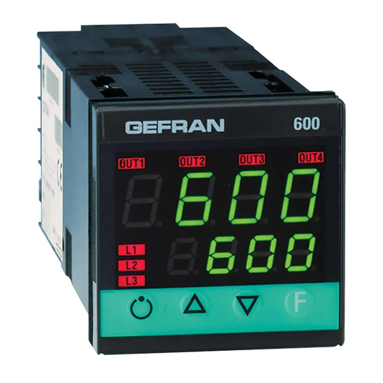
600
CONTROLLER
70
45
45
!
For correct and safe
installation, follow the
instructions and
observe the warnings
contained in this
manual.
USER'S MANUAL
SOFTWARE VERSION 2.09
Edition 01.04.2008
GEFRAN spa via Sebina, 74
25050 Provaglio d'Iseo (BS) ITALIA
Tel. 0309888.1 - Fax 0309839063
Internet: http://www.gefran.com
2 • TECHNICAL SPECIFICATIONS
Display
Keys
Accuracy
Main input (settable digital filter)
Type TC Thermocouples
(ITS90)
Cold junction error
RTD type (scale configurable within indicated
range, with or without decimal point) (ITS90)
Max line resistance for RTD
PTC type / NTC Type
Safety
70
°C / °F selection
Linear scale ranges
Controls
pb - dt - it
Action
Control outputs
Maximum power limit heat / cool
Cycle time
Main output type
Softstart
Fault power setting
Automatic blanking
Configurable alarms
Alarm masking
Type of relay contact
Logic output for static relays
Triac output
Transmitter power supply
Analogue retransmission signal
Logic inputs
Serial interface (optional)
Baud rate
Protocol
Optional ammeter input
Power supply (switching type)
Faceplate protection
Working / Storage temperature range
Relative humidity
Installation
Weight
EMC conformity has been tested with the following connections
FUNCTION
Power supply cable
Relay output cable
Digital communication wire
C.T. connection cable
TC input
Pt100 input
1
2 x 4 digits, green, height 10 and 7mm
4 mechanical keys (Man/Aut, INC, DEC, F)
0.2% full scale ± 1 digit at 25°C room temperature
TC, RTD, PTC, NTC
60mV,1V Riž1Mž; 5V,10V Riž10Kž; 20mA Ri=50ž
Sampling time 120 msec.
J, K, R, S, T, B, E, N (IEC 584-1, CEI EN 60584-1,
60584-2) L GOST, U, G, D, C
custom linearization is available
0,1° / °C
DIN 43760 (Pt100), JPT100
20ž
990ž, 25°C / 1Kž, 25°C
detection of short-circuit or opening of probes, LBA
alarm, HB alarm
configurabile da tastieraconfigurable from faceplate
-1999 to 9999 with configurable decimal point position
PID, Self-tuning, on-off
0,0...999,9 % - 0,00...99,99 min - 0,00...99,99 min
Heat / Cool
on / off, continuous
0,0...100,0 %
0...200 sec
relay, logic, continuous (0....10V / 4...20mA)
0,0...500,0 min
-100,0...100,0 %
Displays PV value, optional exclusion
Up to 3 alarm functions assignable to an output,
configurable as: maximum, minimum, symmetrical,
absolute/deviation, LBA, HB
- exclusion during warm up
- latching reset from faceplate or external contact
NO (NC), 5A, 250V/30Vdc cosϕ=1
24V ±10% (10V min at 20mA)
20...240Vac ±10%, 1A max
Snubberless, inductive and resistive load I
2
10 / 24Vdc, max 30mA short-circuit protection
10V/20mA Rload max 500ž resolution 12 bit
Ri = 4,7Kž (24V, 5mA) or no-voltage contact
RS485, isolated
1200, 2400, 4800, 9600, 19200
Gefran CENCAL / MODBUS
T.A. 50mAac, 50/60Hz, Ri = 10ž
(std) 100 ... 240Vac/dc ±10%
(opt.) 20...27Vac/dc ±10%;
50/60Hz, 8VA max
IP65
0...50°C / -20...70°C
20 ... 85% non-condensing
Panel, plug-in from front
160g for the complete version
CABLE TYPE
LENGTH
1 mm
2
1 m
1 mm
2
3,5 m
0,35 mm
2
3,5 m
1,5 mm
2
3,5 m
0,8 mm
2
compensated
5 m
1 mm
2
3 m
t = 128A
2
s
Advertisement
Table of Contents

Related Manuals for gefran 600


Summary of Contents for gefran 600
- Page 1 Digital communication wire 0,35 mm 3,5 m SERVICE: GEFRAN has a service department. The warranty excludes defects caused C.T. connection cable 1,5 mm 3,5 m by any use not conforming to these instructions.
- Page 2 3 and no. 5 1.5) Outputs: Type 600 controllers have up to 4 outputs, depending on the model. Each output can be mapped via software to perform one or more functions. It is for example possible to assign a combination of alarms to one output relay. It is also possible to assign the main control function to any of the outputs.
-
Page 3: Programming And Configuration
On the 600-R-?-C-?-? the analog output can only be used for control purposes. The 600-R-?-W-?-? can be configured for analog control or for analog retransmission. Change from 0-20 (0-10V) to 4-20mA (2-10V): This is a software setting. In the "Out" menu set rL.3=64 heat) or 65 (cool) for control purposes. For retransmission go into the "U.CAL"... -
Page 4: Info Display
2) Configuration menus: 2.1) Description of menus: The programming of the 600 controller is divided into 10 menus: INF: the information menu contains general information (software version etc.) CFG: the configuration menu contains all parameters affecting the control behavior (enabling of self-/autotune, PID parameters, hysteresis, softstart time, loop break power etc.) - Page 5 + 32 Hys becomes delay time when alarm trips (0...999 sec.) Set Ct.2=1 If the control output switches a solidstate relay (excluding symmetrical absolute) (controller type 600-R-D-0-0-1). + 64 Hys becomes delay time when alarm trips (0...999 min.) Set Ct.2=20 if the control output switches a contactor or relay (excluding symmetrical absolute) (controller type 600-R-R-0-0-1).
- Page 6 • Prot Protection code Protecting (“tamper proofing”) the unit: Prot Display Modification SP, alarms SP, alarms To get into the Prot. Menu (changing the protection level) hold the “F” key SP, alarms down until “PASS” appears in the top display. Release the “F” key and use the up/down arrow keys to enter the password “99”.
- Page 7 7 • COMPREHENSIVE CONFIGURATION The comprehensive menu is enabled by setting the protection level Pro= 128: Press and hold the "F" key down until you get to PAS then release the "F" key. Use the UP/DOWN arrow keys to enter the password 99 Now press the "F"...
- Page 8 TC E °C -100/750 -100.0/750.0 TC E °F -148/1382 -148.0/999.9 TC N °C 0/1300 0.0/999.9 TC N °F 32/2372 32.0/999.9 L-GOST °C 0/600 0.0/600.0 L-GOST °F 32/1112 32.0/999.9 TC U °C -200/400 -199.9/400.0 TC U °F -328/752 -199.9/752.0 TC G °C 0/2300 0.0/999.9...
- Page 9 LS.2 Minimum limit auxiliary 0.0 ... 999.9 input scale HS.2 Maximum limit auxiliary 0.0 ... 999.9 input scale oF.2 Offset correction -99.9 ... 99.9 of aux input scale points Lo.L Lower limit for setting SP Lo.S ... Hi.S and absolute alarms Hi.L Upper limit for setting SP Lo.S ...
- Page 10 rL.1 Out 1 Allocation of reference signa rL.o.1, rL.o.2, rL.o.3, rL.o.4 Function of main output relay/logic (OUT1) HEAT (control output for heating) rL.2 COOL (control output for cooling) Out 2 AL1 - alarm 1 Allocation of AL2 - alarm 2 reference signal AL3 - alarm 3 AL.HB - alarm HB...
- Page 11 • Prot Protection code Prot Display Modification SP, In2, alarms, OuP, INF SP, alarms SP, In2, alarms, OuP, INF SP, In2, OuP, INF to disable InP, Out to disable CFG, Ser, + 16 to disable SW “power-up - power down” + 32 disable manual power latching + 64 to disable manual power modification +128 enables full configuration...
- Page 12 AL.nr Alarm 1 Alarm 2 Alarm 3 AL.n Select number of disabled disabled disabled enabled alarms enabled disabled disabled disabled enabled disabled enabled enabled disabled disabled disabled enabled enabled disabled enabled disabled enabled enabled enabled enabled enabled + 8 to enable HB alarm + 16 to enable LBA alarm b u t t No function (key disenabled)
- Page 13 Unit identification code 0 ... 9999 _PAr Parity No parity Parity selection Even Sr.P Serial interface SER.P Serial protocol protocol CENCAL GEFRAN MODBUS RTU s.0u Virtual instrument 0 ... 31 outputs Outputs OUTW OUT4 OUT3 OUT2 OUT1 S.in Virtual instrument 0 ...
-
Page 14: Hardware Parameters
See note 9 "oFS." Allows offset correction of the main input. It is normally set to "0". "FT.2" Sets the filtering of the auxiliary Input signal (applies only to 600-R-?-H-?) "LS.2" this is the minimum auxiliary input scale (applies only to 600-R-?-H-?) "HS.2"... -
Page 15: Output Parameters
"rL.2" sets the function of out2 (terminals 19 + 20). Normally rL.2=0, (main output for heating) "rL.3" sets the function of out3 (terminals 5 + 6). It only applies to units with a third output. For controllers with analog control output (600-R-?-C---) this is set as the main output For Heating (rL.3=0) "rL.4"... -
Page 16: Configuration Parameters
"Hy.3" sets the hysteresis for output 3 and is a % of the input range. "Hb.t" sets the the waiting period for the heater break alarm (only applies to 600-R-?-H---) "Lb.t" sets the the waiting period for the loop break alarm. (Lb.t=0 to disable) "Lb.P"... -
Page 17: Decimal Point
Changing the input scale also affects the proportional band in PID control because h.Pb and c.Pb are a % of the input range. • Standard Sensor The Gefran 600 controller allows changing of the sensor scale. For standard temperature sensors (thermocouples, Pt100…) the Lo.S and Hi.s parameters should normally correspond with the minimum and maximum temperature scale of the particular sensor, as listed in the input table. - Page 18 11 • CONTROLS c_Pb SP+cSP c_Pb SP+cSP h_Pb h_Pb time time +100% +100% Control output Control output -100% -100% Control output with proportional action only if proportional heating band Control output with proportional action only if proportional heating band overlaps proportional cooling band. overlaps proportional cooling band.
- Page 19 For combined heat/cool control two outputs will be occupied. Hence you need a controller with more than two outputs (e.g. 600-R-D-R-0-1) if you want heat/cool control with alarm. If you use a controller with only two outputs for heat/cool control (e.g 600-R-R-0-0-1), no spare output for alarm is available, hence the alarm should be disabled by setting Al.n=0 It is possible to enable up to 3 alarms.
-
Page 20: Manual Mode
15 • HEAT BREAK ALARM (AUX. INPUT 2) controllers with input/output 3 option ="H" monitor the load current via a 50mA secondary current transformer (refer to Gefran CT type 330200 and 330201). The load current can be displayed via the bottom SV display (set dSP=1 in Hrd menu). The scaling of the input is achieved by setting LS.2 (normally LS2=0) and HS.2 in the InP menu. -
Page 21: Display Functions
17 • DISPLAY FUNCTIONS • SV Display (bottom display) The function of this display can be configured by setting the dSP parameter in the Hrd menu. Normally dSP=0, showing the control setpoint. However the display can also be configured to display the value of the auxiliary input, the output power or the deviation of the process variable from the setpoint. - Page 22 • Selftune Selftune is performed on a cold process (power-up) and is a once-off process. At power-up the controller will provide full power for a brief moment, then monitor rise and fall of the process variable, calculate the PID parameters and the revert to normal control. It is useful to configure one of the three LEDs L1, L2 or L3 to indicate or flash while autotuning is active.
-
Page 23: Cycle Time
Typical values: Ct.2=1 If the control output switches a solidstate relay (controller type 600-R-D-0-0-1). Ct.2=20 if the control output switches a contactor or relay (controller type 600-R-R-0-0-1). Ct.2= -0.1 for fast hotrunner applications (only on controller type 600-R-D-?-?-1-R62). 21 • SAFOTSTART AND GRADIENT (RAMPING) FUNCTION •... - Page 24 Wire length: 5,50m PTC 7 x 25 5m • RS232 / TTL interface for GEFRAN instrument configuration N.B. RS232 interface for PC configuration is supplied with the WINSTRUM programming software. Make connection with instrument powered but with inputs and outputs disconnected.
- Page 25 VAC. Resistors must be at least 2W); fit a 1N4007 diode in parallel with the coil of inductive loads that operate in DC. GEFRAN spa will not be held liable for any injury to persons and/or damage to property deriving from tampering, from any incorrect or...
Need help?
Do you have a question about the 600 and is the answer not in the manual?
Questions and answers