
Related Manuals for Lightware DVI-OPT-TX220-Pro


Summary of Contents for Lightware DVI-OPT-TX220-Pro
- Page 1 User’s Manual DVI-OPT-TX220-Pro DVI-OPT-TX220-ST-Pro DVI-OPT-RX220-Pro DVI-OPT-RX220-ST-Pro Fiber Multimedia Extender...
- Page 2 DVI-OPT-220-Pro series – User's Manual Important Safety Instructions Waste Electrical & Electronic Equipment Common Safety Symbols WEEE Class I Apparatus Construction. Symbol Description This marking shown on the product or its literature, This equipment must be used with a mains power system with a indicates that it should not be disposed with other protective earth connection.
-
Page 3: Dvi-Opt-220-Pro Series – User's Manual
Hardware/Firmware/Software environment: recommended to read and keep in every case! Item Version Lightware Device Controller (LDC) software 1.22.1 ATTENTION! Useful information to perform a successful procedure; it is recommended to read. Lightware Bootloader Software 3.3.2 Controller firmware 1.1.8... -
Page 4: Table Of Contents
2.1.2. Through Furniture Mounting ............7 9.3.2. Types of Serial Cables ..............35 6. LW2 PROGRAMMERS’ REFERENCE ..........23 2.1.3. Rack Shelf Mounting ................ 7 9.3.3. RS-232 Signal Transmission over Lightware Extender Devices .. 35 6.1. LW2 Protocol Description............23 2.2. Connecting Steps .................8 10. APPENDIX ..................36 6.2. General LW2 Commands .............23 10.6. Powering Options ...............8... -
Page 5: Introduction
25 - 165MHz pixel clock frequency: from 640x480@60Hz to signal instability and distortion caused by long cables 1920x1200@60Hz or 2048x1080@60Hz resolutions. Thank You for choosing Lightware’s DVI-OPT-220-Pro series device. In the first or connector reflections. The extenders have an RS-232 serial port for remote control chapter we would like to introduce the device highlighting the most important applications and firmware upgrade. -
Page 6: Typical Application
DVI cabIe DVI cabIe DVI Monitor DVI Monitor PC or Mac DVI Monitor DVI cabIe DVI cabIe DVI cabIe DVI Monitor e in DVI-OPT-TX220-Pro DVI-OPT-RX220-Pro NEUTRIK ® DVI-OPT-RX220-Pro opticalCON LC-LC fiber DUO HYBRID DVI cabIe optical cable Power cable Power cable... -
Page 7: Installation
2. Installation DVI-OPT-220-Pro series – User's Manual 2.1. Mounting Options 2.1.3. Rack Shelf Mounting Step 1. Turn the unit upside down. Devices can be mounted several ways, depending on the application. Step 2. Put the rack shelf upside down on the unit, and position it to get Besides using with rack shelf a mounting bracket is available which the mounting holes aligned. -
Page 8: Connecting Steps
Power Power Set the power selector switch to II (only on DVI-OPT-RX220-Pro) Connect a compatible Lightware fiber Connect a compatible Lightware fiber receiver unit with a multimode fiber cable transmitter unit with a multimode fiber Connect a DVI-OPT-TX220-Pro to the fiber output connector. Connect cable to the FIBER INPUT connector. -
Page 9: Product Overview
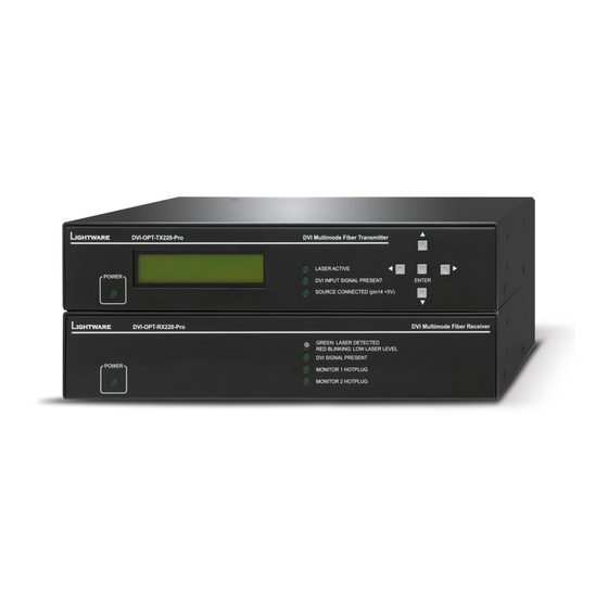
3. Product Overview DVI-OPT-220-Pro series – User's Manual 3.1. Transmitters 3.1.1. Front View INFO: The front view of DVI-OPT-TX220-Pro and DVI-OPT-TX220-ST-Pro is almost the same; the only difference is the type designation. DVI-OPT-TX220-ST-Pro DVI Multimode Fiber Transmitter DVI-OPT-TX220-PR LASER ACTIVE... -
Page 10: Rear View
3. Product Overview DVI-OPT-220-Pro series – User's Manual 3.1.2. Rear View DVI-OPT-TX220-Pro AC connector Standard IEC power connector. Accepts 100 to 240 Volts, 50 or 60 Hz power sources. Serial port 9-pole D-SUB female connector for serial RS 232 communication; see... -
Page 11: Receivers
3. Product Overview DVI-OPT-220-Pro series – User's Manual 3.2. Receivers 3.2.2. Rear View DVI-OPT-RX220-Pro 3.2.1. Front View INFO: The front view of DVI-OPT-RX220-Pro and DVI-OPT-RX220-ST-Pro is almost the same; the only difference is the type designation. DVI-OPT-RX220-ST-Pro DVI Multimode Fiber Receiver GREEN: LASER DETECTED RED BLINKING: LOW LASER LEVEL DVI SIGNAL PRESENT... -
Page 12: Electrical Connections
Neutrik OpticalCON Duo Connector 300Ω DVI signal present D-sub connector pin assignment for standard RS-232 Pin 1: DVI detect (+5V) DVI-OPT-RX220-Pro and DVI-OPT-TX220-Pro models Pin nr. Pinout Pin 2: Laser detect (+5V) have Neutrik opticalCON connector (NO2-4FDW type Pin 3: GRD NC - non-connected 300Ω... -
Page 13: Multimode Single Fiber Extender Concept
Port Diagram of Optical Interface The Neutrik opticalCON DUO cable has two fiber channels, named channel A and channel B. Since Lightware fiber extenders use only one fiber for signal transmission, the other fiber can be used by other optical devices. -
Page 14: Operation
The extenders have an LCD menu and navigation buttons which make O peration EmulatedEDID F49 to the manufacturer. Lightware the possibility to change certain settings and display basic information factory presets have LWR as the via the front panel. -
Page 15: Viewing Attached Monitor
INFO: Location D02 has a special function. If a monitor is connected to LOCAL MONITOR OUT, then its EDID is copied to location D02. If no monitor is connected to the output then the last connected monitor’s EDID is shown. INFO: Lightware factory presets have LWR as the manufacturer. -
Page 16: Software Control - Lightware Device Controller
The extender can be controlled by a computer through the LAN, RS-232 and exist for all users installed for all users USB ports using Lightware Device Controller (LDC). The software can be Comparison of the Installation Types installed on a Windows PC or Mac OS X. The application can be downloaded from www.lightware.com. -
Page 17: Establishing The Connection
5. Software Control – Using Lightware Device Controller DVI-OPT-220-Pro series – User's Manual 5.2. Establishing the Connection 5.3. I/O Parameters Menu The extenders can be controlled from a Windows or OS X based computer using the LDC through RS 232 After connecting to the device, this menu appears by default showing the current state of input and output connection. -
Page 18: Edid Menu
5. Software Control – Using Lightware Device Controller DVI-OPT-220-Pro series – User's Manual 5.4. EDID Menu Port settings (receiver) The window shows the adjustable parameters for the input. Input1: Advanced EDID Management can be accessed by selecting the EDID menu. There are two panels: left one contains Source EDIDs, right one contains Destination slots where the EDIDs can be emulated or copied. -
Page 19: Sources And Destinations
EDID is copied to the input; if a new monitor is attached to the output, the emulated EDID is changed automatically. INFO DVI-OPT-TX220-Pro can handle both 128 Byte EDID and 256 Byte extended EDID structures. 5.4.2. EDID Operations Changing the Emulated EDID Step 1. -
Page 20: Editing An Edid
Select an EDID from the left panel and press the Edit button to display Advanced EDID Editor window. The Since above mentioned Advanced EDID Editor needs more complex knowledge about EDID, Lightware editor can read and write all descriptors, which are defined in the standards, including the additional CEA introduced a wizard-like interface for fast and easy EDID creation. -
Page 21: Settings
Browse command file The LDC is able to send a custom command file to the extender. The command file can be generated by Lightware support. This is needed when some special commands has to be used for configuring or troubleshooting. -
Page 22: Terminal Menu
5. Software Control – Using Lightware Device Controller DVI-OPT-220-Pro series – User's Manual 5.7. Terminal Menu The general-purpose of this serial terminal is intended mainly for testing and debugging purposes. All commands can be used here that are discussed in LW2 Programmers’... -
Page 23: Lw2 Programmers' Reference
Input number in 2 digit ASCII format (01, 02, 10, 12 etc.) L W2 Programmers’ Reference <out²> Output number in 2 digit ASCII format (01, 02, 10, 12 etc.) Lightware DVI-OPT-220-Pro series extenders can be controlled with external <loc> Location number in 1, 2 or 3 digit ASCII format devices which can communicate according to the extender protocol. -
Page 24: View Product Type
→ {fc} Response (<PRODUCT_TYPE>)CrLf ← (I: DVI-OPT-TX220-PRO)CrLf Response (CF●<DESC>)CrLf (CF DVI-OPT-TX220-PRO FW:1.1.8) ← (CF●<DESC>)CrLf … Explanation: The connected device is a DVI-OPT-TX220-Pro. (CF END)CrLf (CF END)<CR><LF> ← Legend: <PRODUCT_TYPE> shows type. 6.2.3. View Serial Number Explanation: The device has one control panel. -
Page 25: Edid Management
6. LW2 Programmers’ Reference DVI-OPT-220-Pro series – User's Manual 6.3. EDID Management Location EDID type Description That is valid to all inputs, but since the transmitter has one input, the 6.3.1. View Emulated EDID on the Input <loc1> result will be the same as typing E1. -
Page 26: View Edid Header
6. LW2 Programmers’ Reference DVI-OPT-220-Pro series – User's Manual 6.3.5. View EDID Header 6.3.7. Upload EDID Content to a Location Description: Shows basic information about EDIDs in the memory. Description: EDID hex bytes can be written directly to the user programmable memory locations. Sequence Format Example... -
Page 27: Delete Edid From Memory
6. LW2 Programmers’ Reference DVI-OPT-220-Pro series – User's Manual 6.3.8. 6.4. Extender Initiated Commands Delete EDID from Memory Description: Clear EDID from memory location <loc>. 6.4.1. EDID Status Changed (Transmitter) Format Example Description: This is sent after any command which changed the EDID table (EDID copy, EDID switch), or after a new EDID source e.g. -
Page 28: Quick Summary
6. LW2 Programmers’ Reference DVI-OPT-220-Pro series – User's Manual 6.5. Quick Summary General LW2 Commands See in Operation Command section Query Control Protocol 6.2.1 {P_?} View Product Type 6.2.2 View Serial Number 6.2.3 View Firmware Version of the CPU 6.2.4 View Installed Board(s) 6.2.5... -
Page 29: Firmware Upgrade
This chapter is meant to help customers perform firmware upgrades on our EDID emulation table (E) F49 will be set on the input products with Lightware Bootloader software. To get the latest software and Input port settings Set to factory defaults firmware pack , please contact support@lightware.com. - Page 30 7. Firmware Upgrade DVI-OPT-220-Pro series – User's Manual When the connection is established, Step 6. Upgrade firmware(s) Step 7. Done! Firmware upgrade device switched Click UPGRADE SELECTED FIRMWARES button on the left side. A If the upgrade was successful, the following window pops up: in progress...
-
Page 31: Troubleshooting
8. Troubleshooting DVI-OPT-220-Pro series – User's Manual At first, check front panel LEDs and take the necessary steps according to their states. For more information about status, LEDs refer to the Front View Rear View sections. Symptom Root cause Action... - Page 32 Error logs and backup files from the Lightware Device Controller software. ▪ The more of the above information you can give us the better. Please send these information to the Lightware Support Team to speed up the troubleshooting process.
-
Page 33: Technologies
(dynamic EDID emulation). information about additional Detailed Timings, audio capabilities, For example, the Lightware device can be set up to emulate a sink speaker allocation and HDMI capabilities. It is important to know that device, which is connected to one of the outputs. -
Page 34: Pixel Accurate Reclocking
Without reclocking, sparkles, noise, and jaggies appear on the image. Lightware’s sophisticated Pixel Accurate Reclocking technology fixes more problems than general TMDS reclocking. It removes not only intra-pair skew but inter-pair skew as well. The Pixel Accurate... -
Page 35: Serial Management
DVI-OPT-220-Pro series – User's Manual 9.3. Serial Management 9.3.3. RS-232 Signal Transmission over Lightware Extender Devices The following examples describe the detailed integration of Lightware devices between different RS-232 pin 9.3.1. General Information assignment units. There are two types of devices in general serial communication: INFO: DVI-OPT-220-Pro series extenders are DCE units (according to their pinouts) with female plugs. -
Page 36: Appendix
10. Appendix DVI-OPT-220-Pro series – User's Manual 10.1. Specification Optical Port Fiber type ............ 50/125 SC Multimode fiber General Laser wavelengths ......4ch. CWDM: 778; 800; 825; 850 nm Compliance ..................CE Laser class specification ............Class 3R EMI/EMC compliance ....... -
Page 37: Factory Edid List
10. Appendix DVI-OPT-220-Pro series – User's Manual 10.2. Factory EDID List 10.3. Maximum Extension Distances The below table shows the transmission distances via optical cable Mem. Resolution Mem. Resolution between the DVI-OPT-220-Pro series extenders depending on the 640 x 480 @ 60.0 640 x 480 @ 59.94... -
Page 38: Mechanical Drawings
10. Appendix DVI-OPT-220-Pro series – User's Manual 10.5. Mechanical Drawings INFO: DVI-OPT-TX220-pro can be seen on the pictures; the external dimensions and the fixing holes of all units are the same. Front View Left View DVI-OPT-TX220-Pro DVI Multimode Fiber Transmitter... -
Page 39: Further Information
1.4. Product failures from six (6) months to the end of the warranty period will either be repaired or replaced at the discretion of Lightware. If Lightware chooses to replace the product then the replacement will be warranted for the remainder of the original unit’s warranty period.
Need help?
Do you have a question about the DVI-OPT-TX220-Pro and is the answer not in the manual?
Questions and answers