Cisco NCS 4000 Series Hardware Installation
Hide thumbs
Also See for NCS 4000 Series:
- Hardware installation manual (82 pages) ,
- Manual (52 pages) ,
- Troubleshooting manual (44 pages)
Table of Contents
Advertisement
Quick Links
Download this manual
See also:
Troubleshooting Manual
Advertisement
Chapters
Table of Contents
Troubleshooting

Related Manuals for Cisco NCS 4000 Series


Summary of Contents for Cisco NCS 4000 Series
- Page 1 Hardware Installation Guide for Cisco NCS 4000 Series First Published: 2016-09-12 Last Modified: 2017-09-13 Americas Headquarters Cisco Systems, Inc. 170 West Tasman Drive San Jose, CA 95134-1706 http://www.cisco.com Tel: 408 526-4000 800 553-NETS (6387) Fax: 408 527-0883...
- Page 2 Cisco and the Cisco logo are trademarks or registered trademarks of Cisco and/or its affiliates in the U.S. and other countries. To view a list of Cisco trademarks, go to this URL: www.cisco.com/go/trademarks . Third-party trademarks mentioned are the property of their respective owners. The use of the word partner does not imply a partnership relationship between Cisco and any other company.
-
Page 3: Table Of Contents
C H A P T E R 3 Basic Site and Installation Planning Equipment Rack Considerations Aisle Spacing and Maintenance Access Floor Plan Front and Rear Clearances Cable Management Route Processor Cables Interface Cables Hardware Installation Guide for Cisco NCS 4000 Series... - Page 4 Installing Route Processor Cards, Fabric Cards, and Line Cards C H A P T E R 5 About Installing Cards and Associated Components Preventing Electrostatic Discharge Guidelines for Installing and Removing a Card Installing and Removing a Filler Card Hardware Installation Guide for Cisco NCS 4000 Series...
- Page 5 C H A P T E R 6 Removing and Replacing Chassis Components Removing a Line Card Replacing/Reinserting a Line Card Removing an RP Card Removing a Fabric Card Removing the Power Components Removing AC Input Power Cords Hardware Installation Guide for Cisco NCS 4000 Series...
- Page 6 C H A P T E R 8 Chassis Specifications Power Specifications Environmental Specifications Regulatory, Compliance, and Safety Specifications Installation Roadmap for NCS 4009 C H A P T E R 9 Installation Roadmap Hardware Installation Guide for Cisco NCS 4000 Series...
- Page 7 Reconnecting DC Power Powering On the Chassis Installing Route Processor Cards, Fabric Cards, and Line Cards C H A P T E R 1 2 About Installing Cards and Associated Components Preventing Electrostatic Discharge Hardware Installation Guide for Cisco NCS 4000 Series...
- Page 8 C H A P T E R 1 3 Removing a Line Card Replacing or Reinserting a Line Card Removing an RP Card Removing a Fabric Card Removing the Power Components Removing AC Input Power Cords Hardware Installation Guide for Cisco NCS 4000 Series viii...
- Page 9 Line Card Product IDs Cosmetic Product IDs Accessory Product IDs System Specifications C H A P T E R 1 5 Chassis Specifications Power Specifications Environmental Specifications Regulatory, Compliance, and Safety Specifications Hardware Installation Guide for Cisco NCS 4000 Series...
- Page 10 Contents Hardware Installation Guide for Cisco NCS 4000 Series...
-
Page 11: Audience
This hardware installation guide describes how to install and remove a Cisco Network Convergence System (NCS) 4016 chassis and NCS 4009 chassis and its components. The Cisco NCS 4016 chassis and Cisco NCS 4009 chassis are converged optical service platforms in the Cisco NCS 4000 Series family. - Page 12 This appendix contains tables that list the specifications for the main components of the Cisco NCS 4016 chassis. Installation Roadmap for NCS 4009, on page 147 This chapter lists the steps to install the Cisco NCS 4009 chassis and its components and prepare the system for operation.
-
Page 13: Conventions
Means the following information will help you solve a problem . The tips information might not be troubleshooting or even an action, but could be useful information, similar to a Timesaver. Hardware Installation Guide for Cisco NCS 4000 Series xiii... - Page 14 Tämä varoitusmerkki merkitsee vaaraa. Tilanne voi aiheuttaa ruumiillisia vammoja. Ennen kuin käsittelet laitteistoa, huomioi sähköpiirien käsittelemiseen liittyvät riskit ja tutustu onnettomuuksien yleisiin ehkäisytapoihin. Turvallisuusvaroitusten käännökset löytyvät laitteen mukana toimitettujen käännettyjen turvallisuusvaroitusten joukosta varoitusten lopussa näkyvien lausuntonumeroiden avulla. SÄILYTÄ NÄMÄ OHJEET Hardware Installation Guide for Cisco NCS 4000 Series...
- Page 15 Utilize o número da instrução fornecido ao final de cada aviso para localizar sua tradução nos avisos de segurança traduzidos que acompanham este dispositivo. GUARDE ESTAS INSTRUÇÕES Hardware Installation Guide for Cisco NCS 4000 Series...
- Page 16 Använd det nummer som finns i slutet av varje varning för att hitta dess översättning i de översatta säkerhetsvarningar som medföljer denna anordning. SPARA DESSA ANVISNINGAR Hardware Installation Guide for Cisco NCS 4000 Series...
- Page 17 Brug erklæringsnummeret efter hver advarsel for at finde oversættelsen i de oversatte advarsler, der fulgte med denne enhed. GEM DISSE ANVISNINGER Hardware Installation Guide for Cisco NCS 4000 Series xvii...
-
Page 18: Related Documentation
Related Documentation Related Documentation For complete planning and installation information, see the following documents: • Regulatory Compliance and Safety Information for Cisco NCS 4000 Series • Configuration Guide for Cisco NCS 4000 Series • Command Reference for Cisco NCS 4000 Series... -
Page 19: Obtaining Documentation And Submitting A Service Request
What’s New in Cisco Product Documentation at: http://www.cisco.com/c/en/us/td/docs/general/whatsnew/whatsnew.html Subscribe to What’s New in Cisco Product Documentation , which lists all new and revised Cisco technical documentation as an RSS feed and delivers content directly to your desktop using a reader application. The RSS feeds are a free service. - Page 20 Preface Obtaining Documentation and Submitting a Service Request Hardware Installation Guide for Cisco NCS 4000 Series...
-
Page 21: Installation Roadmap For Ncs 4016
Installation Roadmap This table lists the steps to install the Cisco NCS 4016 chassis and its components and prepare the system for operation. Use this table as a checklist to ensure that all components are properly installed in the correct order. - Page 22 Installation Roadmap for NCS 4016 Installation Roadmap Step Re-install the cosmetic door. Removing and Replacing the Front Door, on page Hardware Installation Guide for Cisco NCS 4000 Series...
-
Page 23: Chassis Overview
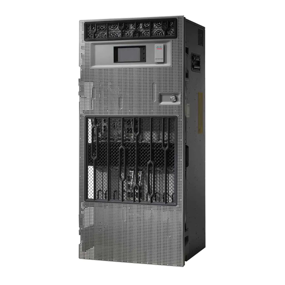
Safety Guidelines, page 13 About the Cisco NCS 4016 Chassis The Cisco NCS 4016 chassis contains an upper card cage and a lower card cage, each with 11 cards (22 total). The following cards are supported: • 2 slots for route processor cards (RPs) •... - Page 24 Chassis Overview About the Cisco NCS 4016 Chassis This figure shows the front view of the Cisco NCS 4016 chassis. Figure 1: Front View of the Cisco NCS 4016 Chassis Power trays (2) Fiber management areas Hardware Installation Guide for Cisco NCS 4000 Series...
-
Page 25: Hardware Installation Guide For Cisco Ncs 4000 Series
Air inlet This figure shows the partial chassis view with craft panel. Figure 2: Partial Chassis View with Craft Panel The following figures show partial rear views of the Cisco NCS 4016 chassis. Hardware Installation Guide for Cisco NCS 4000 Series... -
Page 26: Hardware Installation Guide For Cisco Ncs 4000 Series
There are two air outlets on the rear of the chassis. One is at the top behind the ECUand one is below the Note bottom fan tray. Figure 3: Rear View of the Cisco NCS 4016 AC Chassis Figure 4: Rear View of the Cisco NCS 4016 DC Chassis Hardware Installation Guide for Cisco NCS 4000 Series... -
Page 27: Hardware Installation Guide For Cisco Ncs 4000 Series
Chassis Overview About the Cisco NCS 4016 Chassis Figure 5: Rear View of the Cisco NCS 4016 DC Chassis with DC Power Front Connection Adapter Hardware Installation Guide for Cisco NCS 4000 Series... -
Page 28: Chassis Components
Chassis Overview Chassis Components Chassis Components This table lists the main components of the Cisco NCS 4016 chassis. Table 2: Main Components of the Cisco NCS 4016 Chassis Component Description route processor cards (RPs) Two RP cards (RP0/RP1) are inserted into the front of the chassis. -
Page 29: Hardware Installation Guide For Cisco Ncs 4000 Series
We recommend that you change the air filter every three months. The filter is sold in packs of 5 (Cisco PID NCS4K-FTF=). power trays Two power trays provide redundant power to the chassis. -
Page 30: Chassis Slot Numbers
Chassis Slot Numbers Chassis Slot Numbers This section identifies the location and slot numbers for the cards and power modules that plug into the chassis. Figure 6: Cisco NCS 4016 Chassis Slot Numbers Hardware Installation Guide for Cisco NCS 4000 Series... -
Page 31: Hardware Installation Guide For Cisco Ncs 4000 Series
• The upper four power modules are contained within power tray 0 (PS0). They are named as follows: PS0-PM0, PS0-PM1, PS0-PM2, and PS0-PM3. • The lower four power modules are contained within power tray 1 (PS1). They are named as follows: PS1-PM0, PS1-PM1, PS1-PM2, and PS1-PM3. Hardware Installation Guide for Cisco NCS 4000 Series... -
Page 32: Card Slot Requirements
FC3 are dedicated to fabric cards. Slots RP0 and RP1 are reserved for route processor cards. Shelf assembly slots have symbols indicating the type of cards that you can install in them. Each Cisco NCS 4016 card has a corresponding symbol. The symbol on the card must match the symbol on the slot. -
Page 33: Chassis Cable Management
Slots FC0 through FC3. Only install fabric cards with a cross symbol on the faceplate. Chassis Cable Management The Cisco NCS 4016 chassis has cable management features for the front side only. The horizontal cable management brackets are located above and below the card cages. Safety Guidelines Before you perform any Cisco NCS 4016 chassis installation procedures, review the safety guidelines in this section to avoid injuring yourself or damaging the equipment. -
Page 34: Preventing Electrostatic Discharge
Chassis Overview Preventing Electrostatic Discharge • Use Cisco equipment in accordance with its specifications and product-usage instructions. • Do not work alone if potentially hazardous conditions exist. • Make sure that your installation follows national and local electrical codes: in the United States, National Fire Protection Association (NFPA) 70, United States National Electrical Code;... -
Page 35: Hardware Installation Guide For Cisco Ncs 4000 Series
• Avoid contact between a card and clothing. The wrist strap protects the board from only ESD voltage on the body; ESD voltage on clothing can still cause damage. Figure 8: ESD Jacks — Top of Chassis Top ETSI connection Top ANSI jacket point point Hardware Installation Guide for Cisco NCS 4000 Series... -
Page 36: Hardware Installation Guide For Cisco Ncs 4000 Series
Chassis Overview Preventing Electrostatic Discharge Figure 9: ESD Jacks — Bottom of Chassis Bottom ANSI jacket point Bottom ETSI connection point Hardware Installation Guide for Cisco NCS 4000 Series... -
Page 37: Site Planning Considerations
C H A P T E R Site Planning Considerations This chapter describes the general considerations to address while planning for the installation of the Cisco NCS 4016 chassis. As you plan for your system, keep in mind the specifications listed in... -
Page 38: Equipment Rack Considerations
• Cable management for routing system cables Equipment Rack Considerations A fully loaded Cisco NCS 4016 chassis weighs 412 lb (187 kg). The chassis is mounted in a two-post or a four-post rack. This image shows a four-post rack. Figure 10: Cisco NCS 4016 Chassis Mounted in an Equipment Rack... -
Page 39: Aisle Spacing And Maintenance Access Floor Plan
Aisle Spacing and Maintenance Access Floor Plan The floor plan for the Cisco NCS 4016 chassis must include enough space to install the chassis in the equipment rack and allow sufficient airflow for the system. The floor plan must also provide enough room to access chassis components for maintenance (for example, to remove fan trays, power modules, cables, and air filters). -
Page 40: Front And Rear Clearances
As the size of the routing system increases, the cabling required for the chassis increases. For example, a fully loaded Cisco NCS 4016 chassis has more cables connected to it than a partially loaded chassis. The cabling runs must be carefully planned. The basic configurations for various routing systems should be arranged to minimize the complexity and length of the cable runs. -
Page 41: Interface Cables
• Proper length and termination of cables Noise Control The Cisco NCS 4016 chassis has some built-in noise reduction, such as fan speed control. If the routing system is installed in an environment where excessive noise could be harmful to personnel, some other noise reduction options could be attempted. -
Page 42: Hardware Installation Guide For Cisco Ncs 4000 Series
Site Planning Considerations System Testing, Certification, and Warranties Hardware Installation Guide for Cisco NCS 4000 Series... -
Page 43: Chapter 4 Installing Power Components
C H A P T E R Installing Power Components This chapter provides instructions on how to install and reinstall power components in the Cisco NCS 4016 chassis. It also covers connecting and disconnecting power and powering on the chassis. -
Page 44: Hardware Installation Guide For Cisco Ncs 4000 Series
Installing Power Components Power Connection Guidelines The Cisco NCS 4016 chassis supports two types of AC power cords: International and NEMA (USA). Figure 11: International AC Power Cord (Cisco PID NCS4K-AC-CBL-IEC) Figure 12: NEMA AC Power Cord (Cisco PID NCS4K-AC-CBL-NEMA) -
Page 45: Dc-Powered Chassis
For DC power cables, we recommend 6 AWG high-strand-count copper wire cables, rated 75°C minimum. The size of the cables depends on your chassis location from the source power. Follow your local practices for determining cable size. DC power cables are not available from Cisco, but they are available from any commercial cable vendor. -
Page 46: General Power And Grounding Requirements
For larger system configurations, consult a facilities electrical expert to understand the load that the routing system may put on the facility power plant. General power and grounding requirements are: Hardware Installation Guide for Cisco NCS 4000 Series... -
Page 47: Dc Power Requirements
• Site power planning must include the power requirements for any external terminals and test equipment you will use with your system. Be sure to review the safety warnings in the Cisco Network Convergence System Regulatory Compliance Note and Safety Information for the Cisco Network Convergence System 4000 Series Routers before attempting to install the routing system. -
Page 48: Ac Power Requirements
◦ Each AC power shelf contains four specific single phase AC inlet connectors. These connectors can accept four AC power cords provided by Cisco. AC power cords provided by Cisco can have a IEC-309 plug 32A rated for International power systems, or a NEMA L6-30P plug 30A rated for North America Power Systems. -
Page 49: Hardware Installation Guide For Cisco Ncs 4000 Series
Installing Power Components General Power and Grounding Requirements There are five grounding points on the Cisco NCS 4000 FCC as seen in the figure below. Figure 15: NEBS Bonding and Grounding Points on the Cisco NCS 4000 FCC Hardware Installation Guide for Cisco NCS 4000 Series... -
Page 50: Installing The Chassis Ground Cable
Cisco NCS 4000 FCC. Required Tools and Equipment • Ground lug and screws (provided in chassis accessory kit) • Ground cable • Crimping tool and lug specific die Hardware Installation Guide for Cisco NCS 4000 Series... -
Page 51: Hardware Installation Guide For Cisco Ncs 4000 Series
To ensure a satisfactory ground connection, we recommend 6-AWG multistrand copper ground cable. This cable is not available from Cisco; it is available from any commercial cable vendor such as Panduit. The cable should be sized according to local and national installation requirements. -
Page 52: Installing Dc Power Tray
The following procedure describes how to install a DC power tray in the chassis. Required Tools and Equipment • 6-inch, number-1 Phillips screwdriver • Cisco NCS 4000 FCC power trays (NCS4K-DC-PEM) Steps Follow these steps to install a DC power tray into the chassis: Hardware Installation Guide for Cisco NCS 4000 Series... -
Page 53: Installing Power Modules
The following procedures describe how to install power modules into the chassis. Caution Never force a power module into the power tray if you feel any resistance! Forcing a module into the incorrect tray can cause damage to the module and the tray. Hardware Installation Guide for Cisco NCS 4000 Series... -
Page 54: Installing Dc Power Modules
To prevent damage to the power tray backplane connector, do not use excessive force when inserting the Caution power module into the power tray. Follow these steps to install the DC power modules into the chassis: Hardware Installation Guide for Cisco NCS 4000 Series... -
Page 55: Hardware Installation Guide For Cisco Ncs 4000 Series
Remove the filler caps from the slots where you want to install the power modules. Step 2 Using two hands to support the power module, slide it into the power tray. Figure 18: Inserting the DC Power Module Hardware Installation Guide for Cisco NCS 4000 Series... -
Page 56: Installing The Dc Power Front Connection Adapter
• If the rear to front power adapter is going to be used, then the sub assembly needs to be attached first to the chassis and then both units installed in a rack or cabinet. • The Cisco NCS 4016 chassis should be completely removed from the packaging and installed in the rack or cabinet. -
Page 57: Hardware Installation Guide For Cisco Ncs 4000 Series
Install the DC-FA (front access) brackets on the sides toward the front of the DC adapter. There are three different types of bracket depending upon rack type: ANSI 19 inch or 23 inch and ETSI. Choose the correct type for your specific rack. Figure 20: Installing the DC-FA Brackets Hardware Installation Guide for Cisco NCS 4000 Series... -
Page 58: Hardware Installation Guide For Cisco Ncs 4000 Series
Attach the rear cable guide on top of the chassis toward the rear, and attach the insulator sheet on top of the chassis toward the front . Figure 21: Attaching Rear Cable Guide and Insulator Sheet Rear cable guide Insulator sheet Hardware Installation Guide for Cisco NCS 4000 Series... -
Page 59: Hardware Installation Guide For Cisco Ncs 4000 Series
Installing the DC Power Front Connection Adapter Step 3 Place the DC adapter on top of the chassis using the embossed references on the top chassis cover. Figure 22: Placing DC Adapter on Top of Chassis Hardware Installation Guide for Cisco NCS 4000 Series... -
Page 60: Hardware Installation Guide For Cisco Ncs 4000 Series
Connect the power cables on the rear of the of DC adapter to the chassis terminal blocks. Follow the connections scheme as shown on the labels available on the DC adapter and the chassis. Figure 23: Connecting Power Cables Connect power cables to chassis terminal blocks Hardware Installation Guide for Cisco NCS 4000 Series... -
Page 61: Hardware Installation Guide For Cisco Ncs 4000 Series
Installing Power Components Installing the DC Power Front Connection Adapter Step 5 Install the rear cover to protect the cables. Figure 24: Installing the Rear Cover Hardware Installation Guide for Cisco NCS 4000 Series... -
Page 62: Hardware Installation Guide For Cisco Ncs 4000 Series
Install the chassis and DC adapter subassembly in the rack or cabinet. Attach the chassis brackets and DC brackets to the rack. Figure 25: Chassis Brackets and DC Adapter Brackets DC adapter brackets Chassis brackets (one on other side is not visible) Hardware Installation Guide for Cisco NCS 4000 Series... -
Page 63: Connecting Power To The Chassis
Connecting Power to the Chassis Use one of the following procedures to connect power to your chassis: Connecting Power to an AC-Powered Chassis Follow these steps to connect the AC power cords to the chassis. Hardware Installation Guide for Cisco NCS 4000 Series... -
Page 64: Connecting Power To A Dc-Powered Chassis
Step 7 Proceed to the Powering On the Chassis, on page Connecting Power to a DC-Powered Chassis This section contains the procedures to connect the DC source power cables to a DC-powered chassis. Hardware Installation Guide for Cisco NCS 4000 Series... -
Page 65: Hardware Installation Guide For Cisco Ncs 4000 Series
To prevent injury and damage to the equipment, always attach the ground and source DC power Warning cable lugs to power tray terminals in the following order: (1) positive (+) to positive (+), (2) negative (–) to negative (–). Hardware Installation Guide for Cisco NCS 4000 Series... -
Page 66: Disconnecting Dc Power
Proceed to the Powering On the Chassis, on page Disconnecting DC Power The following sections explain how to disconnect DC power to the Cisco NCS 4000 chassis. Disconnecting AC Power Follow these steps to disconnect an individual AC power cord:... -
Page 67: Disconnecting Ac Power
It is not necessary to disconnect all power from the chassis to replace components, including power Caution modules. Follow these steps to disconnect an individual DC power source from a power tray: Hardware Installation Guide for Cisco NCS 4000 Series... -
Page 68: Disconnecting Dc Power
Disconnect the DC power cables from their terminals in the following order and note the color of each cable: a) Negative (PWR) cables first. b) Positive (RTN) cables last. Step 5 Repeat Step 1 through Step 4 for the other power tray, if installed. Hardware Installation Guide for Cisco NCS 4000 Series... -
Page 69: Reconnecting Dc Power
Set the power tray switch for Feed A to the ON (1) position. This powers on slots PWR MOD 0 through PWR MOD 3. Step 4 Verify that the Power Output LED on each power module in the tray is lit. Step 5 Repeat Step 3 and Step 4 for Feed B. Hardware Installation Guide for Cisco NCS 4000 Series... -
Page 70: Hardware Installation Guide For Cisco Ncs 4000 Series
Installing Power Components Powering On the Chassis Hardware Installation Guide for Cisco NCS 4000 Series... -
Page 71: Installing Route Processor Cards, Fabric Cards, And Line Cards
Line Cards This chapter provides instructions on how to install route processor (RP) cards, fabric cards (FCs), line cards (LCs) and their associated components in the Cisco NCS 4016 chassis. • About Installing Cards and Associated Components, page 51 •... -
Page 72: Guidelines For Installing And Removing A Card
OIR removes power to a specific slot before the card is replaced. The power remains on for all other card slots. • The different cards in the Cisco NCS 4016 chassis are all attached to the chassis itself using a pair of ejector levers and captive screws. The two ejector levers release the card from its backplane connector. -
Page 73: Installing And Removing A Filler Card
This section contains the following procedures: Installing a Filler Card This section describes how to install a filler card in the Cisco NCS 4016 chassis. Prerequisites Before performing this task, open the front door, if installed, and ensure that the slot in which you are about to install the filler card is empty. -
Page 74: Hardware Installation Guide For Cisco Ncs 4000 Series
• If you are installing the card in the top rack, the arrow should be pointing up. • If you are installing the card in the bottom rack, the arrow should be pointing down. Hardware Installation Guide for Cisco NCS 4000 Series... -
Page 75: Removing A Filler Card
Holding the filler card underneath and by the handle, pull it from the slot, and set it carefully aside. About RP Cards The Cisco NCS 4016 chassis supports two route processors (RPs). These cards provide the intelligence of the system by functioning as the shelf controllers for DWDM or OTN applications and by providing route processing and chassis management. -
Page 76: Installing An Rp Card
Installing an RP Card Every Cisco NCS 4016 chassis contains two RP cards in dedicated slots on the right side of the chassis. The RP cards are identical. One RP card installs into slot RP0 on the top side of the chassis, and the second RP card installs into slot RP1 on the bottom side of the chassis. -
Page 77: Hardware Installation Guide For Cisco Ncs 4000 Series
Installing Route Processor Cards, Fabric Cards, and Line Cards Installing an RP Card The following steps describe how to install an RP card. Figure 30: Installing an RP Card Hardware Installation Guide for Cisco NCS 4000 Series... -
Page 78: Hardware Installation Guide For Cisco Ncs 4000 Series
Installing Route Processor Cards, Fabric Cards, and Line Cards Installing an RP Card Direction of insertion Captive screws Hardware Installation Guide for Cisco NCS 4000 Series... -
Page 79: Hardware Installation Guide For Cisco Ncs 4000 Series
Step 10 Using the number-2 Phillips screwdriver or number-2 common (flat-head) screwdriver, turn the two captive screws on the front panel of the card clockwise to seat the card firmly in the slot. Tighten the captive screws using 10.60 pound/force (lbf) inch (1.20 Nm torque). Hardware Installation Guide for Cisco NCS 4000 Series... -
Page 80: Verifying And Troubleshooting The Installation Of An Rp Card
This figure shows the front panel of the RP card. Figure 31: RP Card Front Panel Status LED (card status indicator) Active/ standby LED Attention LED Acknowledge button Sync LED Lamp test button Hardware Installation Guide for Cisco NCS 4000 Series... -
Page 81: Troubleshooting The Rp Card
If the installed or replaced card fails to operate or to power on after installation: • Ensure that the card is seated firmly in the Cisco NCS 4016 chassis slot. One easy way to verify physical installation is to see whether the front faceplate of the card is even with the fronts of the other cards installed in the card cage. -
Page 82: About Fabric Cards
LC slot. The Cisco NCS 4016 chassis supports, the 200G and 400G fabric cards. The 400G fabric card enables 400G traffic using the 400G line card. The datapath link speed of 400G FC-LC is twice that of the 200G FC-LC. -
Page 83: Installing A Fabric Card
Before performing this task, open the front door, if installed. Required Tools and Equipment • ESD-preventive wrist strap • Number-2 Phillips screwdriver or number-2 common (flat-head) screwdriver • FC (Cisco PID NCS4016-FC-M or Cisco PID NCS4016-FC2-M) Steps Hardware Installation Guide for Cisco NCS 4000 Series... -
Page 84: Hardware Installation Guide For Cisco Ncs 4000 Series
Remove the FC from its antistatic packaging. Step 3 Place one hand under the card to support and position the card for insertion into the card cage slot. Avoid touching the card circuitry or any connectors. Hardware Installation Guide for Cisco NCS 4000 Series... -
Page 85: Hardware Installation Guide For Cisco Ncs 4000 Series
To seat the card in the backplane connector, grasp both card ejector levers and pivot them inward toward the handle in the card carrier until they are flush against the front edge of the card carrier. For easier installation, install all FCs before securing any fasteners. Hardware Installation Guide for Cisco NCS 4000 Series... -
Page 86: Hardware Installation Guide For Cisco Ncs 4000 Series
The dark gray arm should be facing up and the light gray arm should be facing down. See the following figure. Figure 33: Attaching the Vertical Cable Management Bracket Light gray arm Dark gray arm Hardware Installation Guide for Cisco NCS 4000 Series... -
Page 87: Verifying The Installation Of A Fabric Card
• When the card is properly installed and no faults are detected, the card status LED turns green. • When the card status LED is solid yellow, either software initialization is in progress during bootup or a fault exists on the board. Hardware Installation Guide for Cisco NCS 4000 Series... -
Page 88: About Line Cards
If the installed or replaced FC fails to operate or power on after installation: • Ensure that the card is seated firmly in the Cisco NCS 4016 chassis slot. One easy way to verify physical installation is to see whether the front faceplate of the FC is even with the fronts of the other cards installed in the card cage. -
Page 89: Hardware Installation Guide For Cisco Ncs 4000 Series
2x100G QPSK DWDM 200Gbps CFP2 ACO 2x200G 16QAM DWDM 400Gbps CFP2 ACO ODU2e 10.3995253164557 QSFP+ BreakOut ODU2 10.0372739240506 QSFP+ BreakOut ODU3 40.3192189830509 QSFP+ ODU3e1 41.774364407 QSFP+ ODU3e2 41.7859685595012 QSFP+ ODU4 104.794445814978 QSFP28 Hardware Installation Guide for Cisco NCS 4000 Series... -
Page 90: Hardware Installation Guide For Cisco Ncs 4000 Series
Parent Payload Child Payload 1 Child Payload 2 ODU4 ODU3 ODU3e1 ODU3e2 ODU2 ODU2e ODU1 ODU1e ODU0 ODUflex 100GE GFP-F OTU3 ODU3 ODU2 ODU2e ODU1 ODU0 40 GE GFP-F ODUflex OTU3e1 ODU2e Hardware Installation Guide for Cisco NCS 4000 Series... -
Page 91: Hardware Installation Guide For Cisco Ncs 4000 Series
Installing Route Processor Cards, Fabric Cards, and Line Cards NCS4K-4H-OPW-QC2 Line Card Parent Payload Child Payload 1 Child Payload 2 OTU3e2 ODU2e ODU1 ODU0 ODUflex OTU2 ODU1 ODU0 ODUflex 10GE GFP-F GFP-F-EXT OC192 Hardware Installation Guide for Cisco NCS 4000 Series... -
Page 92: Hardware Installation Guide For Cisco Ncs 4000 Series
ODU2 ODU2e ODU3e1 ODU2e ODU3e2 ODUflex ODU0 ODU1 ODU2e ODU2 ODUflex ODU0 ODU1 ODU1 ODU0 OTU3 ODU2 ODUflex ODU0 ODU1 ODU1 ODU0 OTU3e2 ODU1 ODU0 ODU2e ODU1 ODU2e ODU0 OTU2 ODU1 ODU0 Hardware Installation Guide for Cisco NCS 4000 Series... -
Page 93: Hardware Installation Guide For Cisco Ncs 4000 Series
Table 9: NCS4K-4H-OPW-QC2 Line Card Descriptions State Description Status Green The LC is properly seated and operating correctly. Yellow The LC has one or more errors detected. No power is applied to the LC. Hardware Installation Guide for Cisco NCS 4000 Series... -
Page 94: 2-Port 100Gbps And 10-Port 10Gbps Otn And Packet Line Card
(GMP) or Generic Framing Procedure - Framed (GFP-F) over ODU4 according to ITU-T G.709 v3 (Section 17.7.5). The 10 GE signals are mapped using GFP-F mapping over ODU2 and BMP mapping over ODU2e respectively. Hardware Installation Guide for Cisco NCS 4000 Series... -
Page 95: Hardware Installation Guide For Cisco Ncs 4000 Series
Port LEDs (one LED on each port) 1 CPAK 1 port CPAK 0 port Status LED Attention LED 1. Port LEDs are triangular in shape and point toward the port that they support. Hardware Installation Guide for Cisco NCS 4000 Series... -
Page 96: 24-Port Low-Rate Otn Line Card
• Four 10GE/OC-192/OTU2 interfaces through SFP+ pluggable optics OTU1 and OTU2 ports support generic forward error correction (GFEC). The card supports ODU2, ODU1, ODU0, and ODUFlex switching functions by interconnecting with the centralized agnostic switch fabric. Hardware Installation Guide for Cisco NCS 4000 Series... -
Page 97: Hardware Installation Guide For Cisco Ncs 4000 Series
Figure 37: 24-Port Low-Rate OTN LC Front Panel and LEDs Status LED Port LEDs (one LED on each port) Attention LED 4 Port LEDs are triangular in shape and point toward the port that they support. Hardware Installation Guide for Cisco NCS 4000 Series... -
Page 98: 20-Port 10Ge Otn Line Card
The 20-port 10GE OTN LC (NCS4K-20T-O-S) line card supports any combination of the following interfaces, up to: • Twenty 10GE interfaces through SFP+ pluggable optics • Twenty OC-192/STM-64 interfaces through SFP+ pluggable optics • Twenty OTU2 interfaces through SFP+ pluggable optics Hardware Installation Guide for Cisco NCS 4000 Series... -
Page 99: Hardware Installation Guide For Cisco Ncs 4000 Series
ODU4, ODU3, ODU2, ODU1, ODU0, and ODUFlex switching functions by interconnecting with the centralized agnostic switch fabric. The line card also supports direct interconnection to other slots within the Cisco NCS 4016 chassis to interconnect switched OTN traffic directly to the NCS 4000 2 x 100G CP-DQPSK - Full C band Tunable DWDM line card. -
Page 100: 2-Port 100Ge Otn Line Card
2-Port 100GE OTN Line Card The 2-port 100GE OTN LC (NCS4K-2H-O-K) supports any combination of 100GE and OTU4 interfaces using Cisco CPAK pluggable optics. Two CPAK receptacles are hosted on the faceplate. Insert CPAK modules in the 2-port 100GE OTN LC handle side down. -
Page 101: Hardware Installation Guide For Cisco Ncs 4000 Series
This figure shows the details of the front panel of the 2-port 100GE OTN LC and LEDs. Figure 39: 2-Port 100GE OTN LC Front Panel and LEDs Status LED Port LEDs (one LED on each port) Attention LED Hardware Installation Guide for Cisco NCS 4000 Series... -
Page 102: 2-Port 100Ge Dwdm Line Card
CPAK pluggable optics that can map each client signal to a single DWDM line interface. Insert CPAK modules in the 2-port 100GE DWDM LC handle side up. Note Hardware Installation Guide for Cisco NCS 4000 Series... -
Page 103: Hardware Installation Guide For Cisco Ncs 4000 Series
Table 14: 2-Port 100GE DWDM LC Descriptions State Description Status Green The LC is properly seated and operating correctly. Yellow The LC has one or more errors detected. No power is applied to the LC. Hardware Installation Guide for Cisco NCS 4000 Series... -
Page 104: Hardware Installation Guide For Cisco Ncs 4000 Series
9 The Attention LED can be lit only by using the hw-module attention-led location CLI command, which is useful for identifying and verifying which card needs attention. Physical Characteristics • Height—11.05 in. (280.6 mm) • Width—1.55 in. (39.4 mm) • Depth—14.25 in. (362 mm) • Weight—7.8 lb (3.53 kg) Hardware Installation Guide for Cisco NCS 4000 Series... -
Page 105: Pluggable Optics Support
OC-192 IR-2 STM-64 S-64.2 OTU2 P1S1-2D2 10GE ZR ONS-SC+-10G-ZR= OC192 LR-2 STM-64 L-64.2 OTU2 P1L1-2D2 C-band tunable ONS-SC+-10G-C= CPAK 100GE SR10 CPAK-100G-SR10 100GE LR4 CPAK-100G-LR4 OTU4 4I1-9D1F QSFP28 100Gbps ONS-QSFP28-LR4 Multi-rate QSFP28, LR Hardware Installation Guide for Cisco NCS 4000 Series... -
Page 106: Installing A Line Card
LC. The chassis may indicate a hardware failure if you do not follow proper procedures. Required Tools and Equipment • ESD-preventive wrist strap • Number-2 Phillips screwdriver or number-2 common (flat-head) screwdriver • LC Steps Hardware Installation Guide for Cisco NCS 4000 Series... -
Page 107: Hardware Installation Guide For Cisco Ncs 4000 Series
You can also connect the ESD-preventive wrist strap leash to any bare metal surface on the chassis. Step 2 Remove the filler card (see the Removing a Filler Card, on page 55) and set it aside. Hardware Installation Guide for Cisco NCS 4000 Series... -
Page 108: Hardware Installation Guide For Cisco Ncs 4000 Series
Use a number-2 Phillips screwdriver or number-2 common (flat-head) screwdriver to tighten the captive screws next to each LC ejector lever to ensure proper EMI shielding and prevent the LC from becoming Hardware Installation Guide for Cisco NCS 4000 Series... -
Page 109: Verifying The Installation Of A Line Card
• When the status LED is solid yellow, either software initialization is in progress during bootup or a fault exists on the card. • When the status LED is blinking yellow, the card is not fully seated. Hardware Installation Guide for Cisco NCS 4000 Series... -
Page 110: Connecting Line Card Network Interface Cables
If the installed or replaced LC fails to operate or to power on after installation: • Ensure that the card is seated firmly into the Cisco NCS 4016 chassis slot. One easy way to verify physical installation is to see whether the front faceplate of the card is even with the fronts of the other cards installed in the card cage. -
Page 111: Hardware Installation Guide For Cisco Ncs 4000 Series
Step 3 Insert the cable connector into its assigned port. You can use the clamp tool (provided in the chassis installation kit) to help insert (or remove) cable Note connectors (and pluggables). Hardware Installation Guide for Cisco NCS 4000 Series... -
Page 112: Hardware Installation Guide For Cisco Ncs 4000 Series
Repeat Step1 through Step 4 for each additional cable connection to that line card. Figure 44: Attaching a Line Card Cable Management Bracket Step 6 Affix fibers to the vertical brackets. The final connections should appear similar to the following figure. Hardware Installation Guide for Cisco NCS 4000 Series... -
Page 113: Connecting Cables To The Rp
This section describes how to connect cables to the console and Ethernet ports on the RP. The console ports are asynchronous serial ports; any devices connected to these ports must be capable of asynchronous transmission. For example, most modems are asynchronous devices. Hardware Installation Guide for Cisco NCS 4000 Series... -
Page 114: Hardware Installation Guide For Cisco Ncs 4000 Series
Console terminal RJ-45 Ethernet cables into RJ-45 ports Modem The ports labeled Ethernet and Console are safety extra-low voltage (SELV) circuits. SELV circuits should Caution be connected only to other SELV circuits. Hardware Installation Guide for Cisco NCS 4000 Series... -
Page 115: Connecting To The Console Port
Ethernet management ports are primarily used as Telnet ports into the Cisco NCS 4016 chassis; they are Caution also used for booting or accessing Cisco software images over a network to which an Ethernet port is directly connected. We strongly caution you to consider the security implications of enabling routing functions on these ports. -
Page 116: Hardware Installation Guide For Cisco Ncs 4000 Series
Connecting to the Ethernet Management Ports Procedure Step 1 Plug the cable directly into the RJ-45 receptacle. Step 2 Connect the network end of your RJ-45 cable to a switch, hub, repeater, or other external equipment. Hardware Installation Guide for Cisco NCS 4000 Series... -
Page 117: Chapter 6 Removing And Replacing Chassis Components
C H A P T E R Removing and Replacing Chassis Components This chapter provides instructions on how to remove and replace components from the Cisco NCS 4016 chassis. • Removing and Replacing Chassis Components, page 97 Removing and Replacing Chassis Components Removing a Line Card This section describes how to remove a line card from the Cisco NCS 4016 chassis. -
Page 118: Hardware Installation Guide For Cisco Ncs 4000 Series
LC at a time. Allow at least 30 seconds for the system to complete its tasks before removing or installing another LC. This procedure is traffic-impacting. Required Tools and Equipment • ESD-preventive wrist strap • Number-2 Phillips screwdriver or number-2 common (flat-head) screwdriver Steps Hardware Installation Guide for Cisco NCS 4000 Series... -
Page 119: Hardware Installation Guide For Cisco Ncs 4000 Series
Attach the ESD-preventive wrist strap to your wrist and connect its leash to the ESD jack located on the front or rear side of the chassis. You can also connect the ESD-preventive wrist strap leash to any bare metal surface on the chassis. Step 2 Identify the card to be removed. Hardware Installation Guide for Cisco NCS 4000 Series... -
Page 120: Replacing/Reinserting A Line Card
Statement 70 Replacing/Reinserting a Line Card This section describes how to replace/reinsert a line card on the Cisco NCS 4016 chassis. Class 1 Laser Product. Statement 113 Warning... -
Page 121: Removing An Rp Card
Traffic will resume after the card is in service. Removing an RP Card This section describes how to remove a route processor card from the Cisco NCS 4016 chassis. Prerequisites Before performing this task, open the front door, if installed. The RP cards are hot-swappable. -
Page 122: Hardware Installation Guide For Cisco Ncs 4000 Series
Removing and Replacing Chassis Components Removing an RP Card The following steps describe how to remove an RP card. Figure 48: Removing an RP Card Hardware Installation Guide for Cisco NCS 4000 Series... -
Page 123: Removing A Fabric Card
ESD-preventive container. If you plan to return a defective card to the factory, repackage it in the shipping container that you received with the replacement card. Removing a Fabric Card This section describes how to remove a fabric card from the Cisco NCS 4016 chassis. Prerequisites Before performing this task, open the front door, if installed. -
Page 124: Hardware Installation Guide For Cisco Ncs 4000 Series
Removing and Replacing Chassis Components Removing a Fabric Card The following steps describe how to remove an FC card. Figure 49: Removing an FC Hardware Installation Guide for Cisco NCS 4000 Series... -
Page 125: Hardware Installation Guide For Cisco Ncs 4000 Series
Touching only the metal card carrier, slide the card from the slot and place it directly into an antistatic bag or other ESD-preventive container. If you plan to return the defective card to the factory, repackage it in its original shipping container. Hardware Installation Guide for Cisco NCS 4000 Series... -
Page 126: Removing The Power Components
Note using the same procedures. While it is possible to remove power components from the Cisco NCS 4016 chassis separately, some parts (such as the power tray) require that other parts be removed first. We recommend that you remove the power components in the order outlined in this section. -
Page 127: Removing A Power Module Slot Cover
This section describes how to remove a power module slot cover from a power module slot in an AC or DC power tray. Steps To remove a power module slot cover from the front of a power tray, perform the following steps: Hardware Installation Guide for Cisco NCS 4000 Series... -
Page 128: Removing An Ac Or Dc Power Module
OIR, so they can be removed and replaced with the power on and the system operating. Steps To remove a power module from the front of a power tray, perform the following steps: Hardware Installation Guide for Cisco NCS 4000 Series... - Page 129 Slide the power module out of its bay in the power tray while supporting it with your other hand. Use the handle available on the front plate of the power module. Figure 51: Removing a Power Module from a Power Tray Hardware Installation Guide for Cisco NCS 4000 Series...
-
Page 130: Removing An Ac Or Dc Power Tray
Removing the Power Components Removing an AC or DC Power Tray This section describes how to remove a power tray from the Cisco NCS 4016 chassis. Prerequisites • Power off the power shelf that houses the power tray you are about to remove. -
Page 131: Removing The Chassis Ground Cable
To prevent injury, avoid sudden twists or lateral moves. Removing the Chassis Ground Cable This section describes how to remove the chassis ground cable on the Cisco NCS 4016 chassis. Hardware Installation Guide for Cisco NCS 4000 Series... -
Page 132: Removing And Replacing The Air Filter
Removing and Replacing the Air Filter This section describes removing and replacing the air filter. The Cisco NCS 4016 chassis is shipped with two air filters installed. The air filters are located in the middle of the chassis behind the plastic grill. - Page 133 Removing and Replacing the Air Filter Procedure Step 1 Un-tighten the thumb screws on either side of the grill. Figure 53: Location of Thumb Screws on Grill Screws on either side of the grill Hardware Installation Guide for Cisco NCS 4000 Series...
- Page 134 Removing and Replacing the Air Filter Step 2 Press the latches on the left and the right to release the bezel. Pull out the bezel. Figure 54: Pressing Latches to Release Bezel Hardware Installation Guide for Cisco NCS 4000 Series...
- Page 135 Removing and Replacing the Air Filter Step 3 Pull out the plungers on the left and the right. Swing the filter trays toward the center of the accessible zone. Figure 55: Pulling Out the Plungers Hardware Installation Guide for Cisco NCS 4000 Series...
-
Page 136: Replacing The Air Filter
Removing and Replacing Chassis Components Replacing the Air Filter Step 4 Pull out the air filters. Figure 56: Pulling Out the Air Filters Replacing the Air Filter To replace the air filter: Hardware Installation Guide for Cisco NCS 4000 Series... -
Page 137: Removing And Replacing The Front Door
Tighten the two captive screws on the front. Removing and Replacing the Front Door This section describes removing and replacing the front door. The Cisco NCS 4016 chassis is shipped with the front door installed. Steps on how to install a key lock are also included. - Page 138 Removing and Replacing Chassis Components Removing and Replacing the Front Door Procedure Step 1 Turn the knob to unlock the door. Figure 57: Knob to Unlock Door Hardware Installation Guide for Cisco NCS 4000 Series...
- Page 139 Removing and Replacing Chassis Components Removing and Replacing the Front Door Step 2 Open the door. Step 3 Loosen the screw to disconnect the ground cable. Figure 58: Disconnecting the Ground Cable Hardware Installation Guide for Cisco NCS 4000 Series...
- Page 140 Removing and Replacing Chassis Components Removing and Replacing the Front Door Hardware Installation Guide for Cisco NCS 4000 Series...
- Page 141 Removing and Replacing Chassis Components Removing and Replacing the Front Door Step 4 Move down the pin to release the door from the chassis hinge. Figure 59: Pin to Release Door from Hinge Hardware Installation Guide for Cisco NCS 4000 Series...
-
Page 142: Replacing The Front Door
Replacing the Front Door Step 5 Move up the door to release the bottom hinge pin. Figure 60: Releasing the Bottom Hinge Pin Replacing the Front Door To replace the front door: Hardware Installation Guide for Cisco NCS 4000 Series... - Page 143 Feed the screw through the ground cable ring lug, through the washer, and then into the machined block. Figure 61: Installing the Door Ground Strap Retrofit Kit Step 3 Using a Phillips screwdriver, insert and tighten the screws. Hardware Installation Guide for Cisco NCS 4000 Series...
-
Page 144: Installing The Optional Key Lock
Swing the door closed and turn the knob to lock. What to Do Next Installing the Optional Key Lock To install the optional key lock: Procedure Step 1 Open the door. Step 2 Disassemble the keyless block: Hardware Installation Guide for Cisco NCS 4000 Series... -
Page 145: Removing And Replacing The Fan Tray
When servicing the system you must remove only one fan tray at a time and replace it in under 2 minutes. Do not remove both fan trays at the same time. This section describes how to remove and replace the upper or lower fan tray. The Cisco NCS 4016 chassis is shipped with two fan trays installed. -
Page 146: Replacing The Fan Tray
Rotate the ejectors down or up, depending upon which fan tray you are removing (top or bottom). Step 3 Slide the fan tray out of the slot. Replacing the Fan Tray To replace the fan tray: Hardware Installation Guide for Cisco NCS 4000 Series... - Page 147 Orient the fan tray as specified on front label, based upon whether you are installing the fan tray in the upper or lower slot. Figure 64: Upper Fan Tray, Arrow Facing Up Figure 65: Lower Fan Tray, Arrow Facing Down Hardware Installation Guide for Cisco NCS 4000 Series...
- Page 148 Check the ejector engagement to be sure it is correct. Complete the ejectors rotation to fully insert the fan trays. Step 5 Tighten the two captive screws to lock the fan tray in place. Hardware Installation Guide for Cisco NCS 4000 Series...
-
Page 149: Performing Online Insertion And Removal Of Fan Tray
Remove the plastic grill from chassis by pressing the tabs in the chassis and place it in secure place. Step 4 Place the trap door in chassis in the same area from where the plastic grill was removed. Hardware Installation Guide for Cisco NCS 4000 Series... - Page 150 Remove top or bottom fan tray as required. Step 9 Close the trap door within 20 seconds after removing the fan tray. See Figure 69: Close Trap Door, on page 130. Figure 69: Close Trap Door Trap Door Hardware Installation Guide for Cisco NCS 4000 Series...
-
Page 151: Removing And Replacing The Craft Panel
Step 13 Re-install the plastic grill into the chassis by tightening the thumb screws. Step 14 Close front door of the chassis by locking the ejector lever. Step 15 Pack the trap door and the old fan tray into box. Return the box to Cisco. Removing and Replacing the Craft Panel This section describes how to remove and replace the craft panel. - Page 152 Removing and Replacing Chassis Components Removing and Replacing the Craft Panel Procedure Step 1 Loosen the two wing-head screws on the right side. Figure 70: Craft Panel Showing Wing-Head Screws Hardware Installation Guide for Cisco NCS 4000 Series...
- Page 153 Removing and Replacing Chassis Components Removing and Replacing the Craft Panel 1- Wing head screws Hardware Installation Guide for Cisco NCS 4000 Series...
-
Page 154: Replacing The Craft Panel
Step 3 Tighten the two connector screws to a torque value of 4.4lbs. Step 4 Close the craft panel and rotate it. Step 5 Tighten the two wing-head screws on the right side. Hardware Installation Guide for Cisco NCS 4000 Series... -
Page 155: Routing The Bits Cables
This section describes how to remove and replace the external connection unit (ECU). The ECU provides all shelf electrical I/O connectivity to the active and standby route-processor line cards. The Cisco NCS 4016 chassis is shipped with the ECU installed. -
Page 156: Replacing The External Connection Unit
Tighten the two captive screws. Step 5 Connect all cables to the ECU faceplate. Replacing an SSD The ECU houses two 2.5-in. solid-state drives (SSDs). Prerequisites • Open the front door, if installed. Hardware Installation Guide for Cisco NCS 4000 Series... - Page 157 To remove an SSD: Procedure Step 1 Loosen the two captive screws. Figure 73: Captive Screws on the SSD 1 - Captive screws Step 2 Slide out the SSD from the ECU slot. Hardware Installation Guide for Cisco NCS 4000 Series...
- Page 158 Replacing the External Connection Unit What to Do Next To replace a SSD: Slide the SSD into the ECU slot and tighten the two captive screws to secure the SSD into place. Hardware Installation Guide for Cisco NCS 4000 Series...
-
Page 159: Chapter 7 System Product Ids
C H A P T E R System Product IDs This appendix provides information about the product IDs for the Cisco NCS 4016 chassis and its components. • System Product IDs, page 139 System Product IDs The tables list the components that make up the routing system, their product IDs (part numbers used to order the components), and descriptions. -
Page 160: Line Card Product Ids
2-port 100GE DWDM line card with CPAK Distributed Route Processor CRS-DRP-Option Cisco CRS-1 Distributed Route Processor (each DRP requires a DRP PLIM) DRP memory option CRS-DRP-MEM-4GCRS-DRP-MEM-8G DRP memory, 4 gigabytes (4G) or 8 gigabytes (8G) Hardware Installation Guide for Cisco NCS 4000 Series... -
Page 161: Cosmetic Product Ids
Cisco NCS craft panel display kit Front door NCS4016-DOOR= Front door NCS4K-ECU= External Connection Unit Accessory Product IDs Table 19: Cisco NCS 4016 Chassis Accessory Product IDs Component Product ID Description Chassis filter NCS4K-FTF= Cisco NCS 4016 chassis air filter,... - Page 162 System Product IDs Accessory Product IDs Hardware Installation Guide for Cisco NCS 4000 Series...
-
Page 163: System Specifications
C H A P T E R System Specifications This appendix contains tables that list the specifications for the main components of the Cisco NCS 4016 chassis. • Chassis Specifications, page 143 • Power Specifications, page 144 • Environmental Specifications, page 145 •... -
Page 164: Power Specifications
Up to 8 power modules can be installed, and only 7are needed to be active at any time. This allows support for 7+1 power redundancy and A and B battery plant dual feeds redundancy. Hardware Installation Guide for Cisco NCS 4000 Series... -
Page 165: Environmental Specifications
Altitude Operating: –200 to 13,100 ft (–61 to 4000 m) at 104°F (40°C) Nonoperating: Up to 16,000 ft (4877 m) at –13°F (–25°C), short-term Chassis airflow Up to 70,792 liters per minute Hardware Installation Guide for Cisco NCS 4000 Series... -
Page 166: Regulatory, Compliance, And Safety Specifications
15 occurrences during that 1-year period. Regulatory, Compliance, and Safety Specifications For information about the regulatory, compliance, and safety standards to which the Cisco NCS 4016 chassis conforms, see Regulatory Compliance and Safety Information for the Cisco Network Convergence System 4000 Series. -
Page 167: Installation Roadmap For Ncs 4009
Installation Roadmap This table lists the steps to install the Cisco NCS 4009 chassis and its components and prepare the system for operation. Use this table as a checklist to ensure that all components are properly installed in the correct order. - Page 168 Installation Roadmap for NCS 4009 Installation Roadmap Hardware Installation Guide for Cisco NCS 4000 Series...
-
Page 169: Chassis Overview
• 2 slots for route processor cards (RPs) • 9 slots for line cards (LCs) • 4 slots for fabric cards (FCs) The Cisco NCS 4009 chassis is rack mountable. It is compatible with the following standard rail spacing: • ANSI 19-inch or 23-inch • ETSI For the ANSI 19-inch rack, the minimum front opening must be 17.72 inches (450 mm) to allow for... - Page 170 Chassis Overview About the Cisco NCS 4009 Chassis The installation of a Cisco NCS 4009 chassis may require space, power, and cooling modifications to a Note facility. Therefore, you should plan the site well in advance of the scheduled delivery of the chassis system.
- Page 171 Chassis Overview About the Cisco NCS 4009 Chassis Figure 75: Partial Chassis View with Craft Panel Hardware Installation Guide for Cisco NCS 4000 Series...
- Page 172 There is an air outlet on the top of chassis below the bottom power tray. Note Figure 76: Rear View of the Cisco NCS 4009 AC Chassis Figure 77: Rear View of the Cisco NCS 4009 DC Chassis Hardware Installation Guide for Cisco NCS 4000 Series...
- Page 173 Chassis Overview About the Cisco NCS 4009 Chassis Figure 78: Rear View of the Cisco NCS 4009 DC Chassis with DC Power Front Connection Adapter Hardware Installation Guide for Cisco NCS 4000 Series...
-
Page 174: Chassis Components
Chassis Overview Chassis Components Chassis Components This table lists the main components of the Cisco NCS 4009 chassis. Table 24: Main Components of the Cisco NCS 4009 Chassis Component Description route processor cards (RPs) Two RP cards (RP0/RP1) are inserted into the front of the chassis. - Page 175 (FSU). A mixture of AC and DC power is not supported in the chassis. Note You must power off the chassis before replacing a power tray. fiber management tray A fiber management tray is located on the top of the chassis. Hardware Installation Guide for Cisco NCS 4000 Series...
-
Page 176: Chassis Slot Numbers
Figure 79: Cisco NCS 4009 Chassis Slot Numbers The chassis has the following card slots: • Nine LC slots (LC0 to LC8) • Two RP slots (RP0 and RP1) • Four FC slots (FC0 to FC3) Hardware Installation Guide for Cisco NCS 4000 Series... - Page 177 • The upper four power modules are contained within power tray 0 (PS0). They are named as follows: PS0-PM0, PS0-PM1, PS0-PM2, and PS0-PM3. • The lower four power modules are contained within power tray 1 (PS1). They are named as follows: PS1-PM0, PS1-PM1, PS1-PM2, and PS1-PM3. Hardware Installation Guide for Cisco NCS 4000 Series...
-
Page 178: Card Slot Requirements
Slots LC0 to LC8 are reserved for line cards. Shelf assembly slots have symbols indicating the type of cards that you can install in them. Each Cisco NCS 4009 card has a corresponding symbol. The symbol on the card must match the symbol on the slot. -
Page 179: Chassis Cable Management
Slots FC0 through FC3. Only install fabric cards with a cross symbol on the faceplate. Chassis Cable Management The Cisco NCS 4009 chassis has cable management features for the front side only. The horizontal cable management bracket is located above the card cage. Safety Guidelines Before you perform any Cisco NCS 4009 chassis installation procedures, review the safety guidelines in this section to avoid injuring yourself or damaging the equipment. -
Page 180: Preventing Electrostatic Discharge
Chassis Overview Preventing Electrostatic Discharge • Use Cisco equipment in accordance with its specifications and product-usage instructions. • Do not work alone if potentially hazardous conditions exist. • Make sure that your installation follows national and local electrical codes: in the United States, National Fire Protection Association (NFPA) 70, United States National Electrical Code;... - Page 181 • Avoid contact between a card and clothing. The wrist strap protects the board from only ESD voltage on the body; ESD voltage on clothing can still cause damage. Figure 81: ESD Jacks — Top of Chassis Top ETSI connection point Top ANSI jacket point Hardware Installation Guide for Cisco NCS 4000 Series...
- Page 182 Chassis Overview Preventing Electrostatic Discharge Figure 82: ESD Jacks — Bottom of Chassis Bottom ANSI jacket point Bottom ETSI connection point Hardware Installation Guide for Cisco NCS 4000 Series...
-
Page 183: Power Connection Guidelines
The power tray provides electrical connections to the chassis backplane. Each power module can be individually plugged in or out from the tray. Each Cisco NCS 4009 chassis is powered by only one type of input: AC or DC. A hybrid (AC+DC) power Caution configuration is not supported. -
Page 184: Ac-Powered Chassis
Power Specifications, on page 274. The Cisco NCS 4009 chassis supports two types of AC power cords: International and NEMA (USA). Figure 83: International AC Power Cord (Cisco PID NCS4K-AC-CBL-IEC) Figure 84: NEMA AC Power Cord (Cisco PID NCS4K-AC-CBL-NEMA) Before connecting AC input power cords to the power system, make sure that the power cords are not Note energized. -
Page 185: Dc-Powered Chassis
For DC power cables, we recommend 6 AWG high-strand-count copper wire cables, rated 75°C minimum. The size of the cables depends on your chassis location from the source power. Follow your local practices for determining cable size. DC power cables are not available from Cisco, but they are available from any commercial cable vendor. - Page 186 Because there is no color code standard for source DC wiring, be sure that power source cables are connected to the power modules using the proper positive (+) and negative (–) polarity: Hardware Installation Guide for Cisco NCS 4000 Series...
-
Page 187: Nebs Supplemental Unit Bonding And Grounding Guidelines
Network Equipment Building System (NEBS) requirements as well as safety compliance requirements. This grounding point is referred to as the NEBS bonding and grounding point. Hardware Installation Guide for Cisco NCS 4000 Series... - Page 188 If you are not installing the chassis in a NEBS environment, you can choose to bypass these guidelines and rely on the safety earth ground connections to the AC power modules. Figure 88: NEBS Bonding and Grounding Point on the Cisco NCS 4009 Chassis Hardware Installation Guide for Cisco NCS 4000 Series...
-
Page 189: Installing The Chassis Ground Cable
To ensure a satisfactory ground connection, we recommend 2-4 AWG multistrand copper ground cable. This cable is not available from Cisco; it is available from any commercial cable vendor such as Panduit. The cable should be sized according to local and national installation requirements. - Page 190 Use the crimping tool mandated by the lug manufacturer to crimp the lug to the ground cable. Step 2 Use the socket wrench to attach the lug and ground cable to the grounding point. Hardware Installation Guide for Cisco NCS 4000 Series...
- Page 191 Use the torque wrench to tighten the bolts to a torque of 35 in-lb (3.95 N-m). Step 4 Connect the other end of the ground cable to a grounding point at your site, according to site requirements. Hardware Installation Guide for Cisco NCS 4000 Series...
-
Page 192: Installing An Ac Or Dc Power Tray
Installing an AC or DC Power Tray Installing an AC or DC Power Tray The power tray is preinstalled on the Cisco NCS 4009 chassis. The following procedure describes how to install an AC or DC power tray in the chassis. -
Page 193: Installing Power Modules
• Off: The output voltage is off. Fault • On: An internal fault is detected within the power module. • Off: No internal faults detected on the power module. Hardware Installation Guide for Cisco NCS 4000 Series... - Page 194 To prevent damage to the power tray backplane connector, do not use excessive force when inserting the Caution power module into the power tray. Follow these steps to install the AC or DC power modules into the chassis: Hardware Installation Guide for Cisco NCS 4000 Series...
- Page 195 Remove the filler caps from the slots where you want to install the power modules. Step 2 Using two hands to support the power module, slide it into the power tray. Figure 92: Example of Inserting the AC Power Module Hardware Installation Guide for Cisco NCS 4000 Series...
- Page 196 Secure the power module into the power tray using the snap hook. Figure 93: Example of Securing the Snap Hook (AC) Step 4 Repeat these steps for the other AC or DC power modules. Hardware Installation Guide for Cisco NCS 4000 Series...
-
Page 197: Installing The Dc Power Front Connection Adapter
• If the rear to front power adapter is going to be used, the sub assembly needs to be attached first to the chassis and then both units installed in a rack or cabinet. • The Cisco NCS 4009 chassis should be completely removed from the packaging and installed in the rack or cabinet. - Page 198 Install the DC-FA (front access) brackets on the sides toward the front of the DC adapter. There are three different types of bracket depending upon rack type: ANSI 19 inch or 23 inch and ETSI. Choose the correct type for your specific rack. Figure 95: Installing the DC-FA Brackets Hardware Installation Guide for Cisco NCS 4000 Series...
- Page 199 Attach the rear cable guide on top of the chassis toward the rear, and attach the insulator sheet on top of the chassis toward the front. Figure 96: Attaching Rear Cable Guide and Insulator Sheet Rear cable guide Insulator sheet Hardware Installation Guide for Cisco NCS 4000 Series...
- Page 200 Installing the DC Power Front Connection Adapter Step 3 Place the DC adapter on top of the chassis using the embossed references on the top chassis cover. Figure 97: Placing DC Adapter on Top of Chassis Hardware Installation Guide for Cisco NCS 4000 Series...
- Page 201 Connect the power cables on the rear of the of DC adapter to the chassis terminal blocks. Follow the connections scheme as shown on the labels available on the DC adapter and the chassis. Figure 98: Connecting Power Cables Connect power cables to chassis terminal blocks Hardware Installation Guide for Cisco NCS 4000 Series...
- Page 202 Installing Power Components Installing the DC Power Front Connection Adapter Step 5 Install the rear cover to protect the cables. Figure 99: Installing the Rear Cover Hardware Installation Guide for Cisco NCS 4000 Series...
- Page 203 Install the chassis and DC adapter subassembly in the rack or cabinet. Attach the chassis brackets and DC brackets to the rack. Figure 100: Chassis Brackets and DC Adapter Brackets DC adapter brackets Chassis brackets (one on other side is not visible) Hardware Installation Guide for Cisco NCS 4000 Series...
-
Page 204: Connecting Power To The Chassis
Connecting Power to the Chassis Use one of the following procedures to connect power to your chassis: Connecting Power to an AC-Powered Chassis Follow these steps to connect the AC power cords to the chassis. Hardware Installation Guide for Cisco NCS 4000 Series... - Page 205 Figure 102: Typical AC Power Connections to an AC Power Tray Step 6 Plug the other end of the AC power cord into the AC source receptacle. Step 7 Proceed to the Powering On the Chassis, on page 191. Hardware Installation Guide for Cisco NCS 4000 Series...
-
Page 206: Connecting Power To A Dc-Powered Chassis
Step 4 Connect the DC power cables in the following order: a) Positive cable first. b) Negative cable last. Step 5 Repeat Step 4 for the other power modules installed in the tray. Hardware Installation Guide for Cisco NCS 4000 Series... - Page 207 7/16 hex socket and torque wrench to a torque of 45 to 50 in-lb. Figure 103: DC Power Tray Rear Panel Figure 104: Typical Power Connections to a Power Tray for a Single DC Power Module — Power System Hardware Installation Guide for Cisco NCS 4000 Series...
- Page 208 Installing Power Components Connecting Power to a DC-Powered Chassis Step 6 Replace the clear plastic safety covers over the connection terminal studs. Figure 105: Typical Plastic Safety Covers over the Power Tray Connection Terminals Hardware Installation Guide for Cisco NCS 4000 Series...
-
Page 209: Disconnecting Ac Or Dc Power
Powering On the Chassis, on page 191. Disconnecting AC or DC Power The following sections explain how to disconnect AC or DC power to the Cisco NCS 4009 chassis. Disconnecting AC Power Follow these steps to disconnect an individual AC power cord:... -
Page 210: Disconnecting Dc Power
Repeat Step 1 through Step 3 for the other power module distribution that needs to be removed. What to Do Next If it becomes necessary to disconnect all DC power from the chassis, follow these steps: Hardware Installation Guide for Cisco NCS 4000 Series... -
Page 211: Powering On The Chassis
LED are solid). Continue with steps 1 and 2 until all inputs have been verified. On the DC power tray, the Power Input LED is lit solid green if both DC feeds are valid and blinks Note green if only a single DC feed is valid. Hardware Installation Guide for Cisco NCS 4000 Series... - Page 212 Set the power tray switch for Feed A to the ON (1) position. This powers on slots PWR MOD 0 through PWR MOD 3. Step 4 Verify that the Power Output LED on each power module in the tray is lit. Step 5 Repeat Step 3 and Step 4 for Feed B. Hardware Installation Guide for Cisco NCS 4000 Series...
-
Page 213: About Installing Cards And Associated Components
Line Cards This chapter provides instructions on how to install route processor (RP) cards, fabric cards (FCs), line cards (LCs) and their associated components in the Cisco NCS 4009 chassis. • About Installing Cards and Associated Components, page 193 •... -
Page 214: Guidelines For Installing And Removing A Card
OIR removes power to a specific slot before the card is replaced. The power remains on for all other card slots. • The different cards in the Cisco NCS 4009 chassis are all attached to the chassis itself using a pair of ejector levers and captive screws. The two ejector levers release the card from its backplane connector. -
Page 215: Installing And Removing A Filler Card
This section contains the following procedures: Installing a Filler Card This section describes how to install a filler card in the Cisco NCS 4009 chassis. Prerequisites Before performing this task, open the front door, if installed, and ensure that the slot in which you are about to install the filler card is empty. - Page 216 Installing Route Processor Cards, Fabric Cards, and Line Cards Installing a Filler Card The following steps describe how to install a filler card. Figure 106: LC Slot Filler Card Hardware Installation Guide for Cisco NCS 4000 Series...
-
Page 217: About Rp Cards
Holding the filler card underneath and by the handle, pull it from the slot, and set it carefully aside. About RP Cards The Cisco NCS 4009 chassis supports two route processors (RPs). These cards provide the intelligence of the system by functioning as the shelf controllers for DWDM or OTN applications and by providing route processing and chassis management. -
Page 218: Installing An Rp Card
Installing an RP Card Every Cisco NCS 4009 chassis contains two RP cards in dedicated slots located on left and right side of the chassis. The RP cards are identical. One RP card installs into slot RP0 on the left side of the chassis, and the second RP card installs into slot RP1 on the right side of the chassis. - Page 219 OIR buttons. If the card does not slide easily into the slot, the orientation may be wrong or the slot is not for an RP. Reorient the RP, if necessary. Hardware Installation Guide for Cisco NCS 4000 Series...
- Page 220 Step 10 Using the number-2 Phillips screwdriver or number-2 common (flat-head) screwdriver, turn the two captive screws on the front panel of the card clockwise to seat the card firmly in the slot. Tighten the captive screws using 10.60 pound/force (lbf) inch (1.20 Nm torque). Hardware Installation Guide for Cisco NCS 4000 Series...
-
Page 221: Verifying And Troubleshooting The Installation Of An Rp Card
Cisco NCS 4009 chassis. Figure 108: RP Card Front Panel Status LED (card status indicator) Active/Standby LED Attention LED Acknowledge button Sync LED Lamp test button Disc LED External USB port Hardware Installation Guide for Cisco NCS 4000 Series... -
Page 222: Troubleshooting The Rp Card
If the installed or replaced card fails to operate or to power on after installation: • Ensure that the card is seated firmly in the Cisco NCS 4009 chassis slot. One easy way to verify physical installation is to see whether the front faceplate of the card is even with the fronts of the other cards installed in the card cage. -
Page 223: About Fabric Cards
LC slot. The Cisco NCS 4009 chassis supports, the 200G and 400G fabric cards. The 400G fabric card enables 400G traffic using the 400G line card. The datapath link speed of 400G FC-LC is twice that of the 200G FC-LC. -
Page 224: Installing A Fabric Card
Before performing this task, open the front door, if installed. Required Tools and Equipment • ESD-preventive wrist strap • Number-2 Phillips screwdriver or number-2 common (flat-head) screwdriver • FC (Cisco PID NCS4009-FC-S or Cisco PID NCS4009-FC2-S) Steps Hardware Installation Guide for Cisco NCS 4000 Series... - Page 225 Installing Route Processor Cards, Fabric Cards, and Line Cards Installing a Fabric Card The following steps describe how to install a fabric card. Figure 109: Installing a Fabric Card Hardware Installation Guide for Cisco NCS 4000 Series...
- Page 226 Step 10 Use the number-2 Phillips screwdriver or number-2 common (flat-head) screwdriver to turn the two captive screws on the front panel of the card clockwise to seat the card firmly in the slot. Tighten the captive screws using 10.60 pound/force (lbf) inch (1.20 Nm torque). Hardware Installation Guide for Cisco NCS 4000 Series...
-
Page 227: Verifying The Installation Of A Fabric Card
• When the card status LED is blinking yellow, the card is not fully seated. • When the card status LED is off, verify that the card is installed correctly. There could be no power applied to the card, a power fault, or a hardware fault. Hardware Installation Guide for Cisco NCS 4000 Series... -
Page 228: About Line Cards
If the installed or replaced FC fails to operate or power on after installation: • Ensure that the card is seated firmly in the Cisco NCS 4009 chassis slot. One easy way to verify physical installation is to see whether the front faceplate of the FC is even with the fronts of the other cards installed in the card cage. - Page 229 QSFP+ BreakOut OTU2f 11.32Gbps QSFP+ BreakOut 2x100G QPSK DWDM 200Gbps CFP2 ACO 2x200G 16QAM DWDM 400Gbps CFP2 ACO ODU2e 10.3995253164557 QSFP+ BreakOut ODU2 10.0372739240506 QSFP+ BreakOut ODU3 40.3192189830509 QSFP+ ODU3e1 41.774364407 QSFP+ Hardware Installation Guide for Cisco NCS 4000 Series...
- Page 230 Table 28: Single Channelization Support Parent Payload Child Payload 1 Child Payload 2 ODU4 ODU3 ODU3e1 ODU3e2 ODU2 ODU2e ODU1 ODU1e ODU0 ODUflex 100GE GFP-F OTU3 ODU3 ODU2 ODU2e ODU1 ODU0 Hardware Installation Guide for Cisco NCS 4000 Series...
- Page 231 Installing Route Processor Cards, Fabric Cards, and Line Cards NCS4K-4H-OPW-QC2 Line Card Parent Payload Child Payload 1 Child Payload 2 40 GE GFP-F ODUflex OTU3e1 ODU2e OTU3e2 ODU2e ODU1 ODU0 ODUflex OTU2 ODU1 ODU0 ODUflex 10GE GFP-F GFP-F-EXT OC192 Hardware Installation Guide for Cisco NCS 4000 Series...
- Page 232 ODU2 ODU2e ODU3e1 ODU2e ODU3e2 ODUflex ODU0 ODU1 ODU2e ODU2 ODUflex ODU0 ODU1 ODU1 ODU0 OTU3 ODU2 ODUflex ODU0 ODU1 ODU1 ODU0 OTU3e2 ODU1 ODU0 ODU2e ODU1 ODU2e ODU0 OTU2 ODU1 ODU0 Hardware Installation Guide for Cisco NCS 4000 Series...
- Page 233 Table 30: NCS4K-4H-OPW-QC2 Line Card Descriptions State Description Status Green The LC is properly seated and operating correctly. Yellow The LC has one or more errors detected. No power is applied to the LC. Hardware Installation Guide for Cisco NCS 4000 Series...
-
Page 234: Port Low-Rate Otn Line Card
The 24-port low-rate OTN LC (NCS4K-24LR-O-S) supports up to: • Twenty-four 1GE interfaces through SFP pluggable optics • Sixteen OC-48/STM-16/OTU1 interfaces through SFP pluggable optics • Four 10GE/OC-192/OTU2 interfaces through SFP+ pluggable optics Hardware Installation Guide for Cisco NCS 4000 Series... - Page 235 Figure 112: 24-Port Low-Rate OTN LC Front Panel and LEDs Status LED Port LEDs (one LED on each port) Attention LED 12 Port LEDs are triangular in shape and point toward the port that they support. Hardware Installation Guide for Cisco NCS 4000 Series...
-
Page 236: Port 10Ge Otn Line Card
The 20-port 10GE OTN LC (NCS4K-20T-O-S) line card supports any combination of the following interfaces, up to: • Twenty 10GE interfaces through SFP+ pluggable optics • Twenty OC-192/STM-64 interfaces through SFP+ pluggable optics • Twenty OTU2 interfaces through SFP+ pluggable optics Hardware Installation Guide for Cisco NCS 4000 Series... - Page 237 ODU4, ODU3, ODU2, ODU1, ODU0, and ODUFlex switching functions by interconnecting with the centralized agnostic switch fabric. The line card also supports direct interconnection to other slots within the Cisco NCS 4009 chassis to interconnect switched OTN traffic directly to the NCS 4000 2 x 100G CP-DQPSK - Full C band Tunable DWDM line card.
-
Page 238: Port 100Ge Otn Line Card
2-Port 100GE OTN Line Card The 2-port 100GE OTN LC (NCS4K-2H-O-K) supports any combination of 100GE and OTU4 interfaces using Cisco CPAK pluggable optics. Two CPAK receptacles are hosted on the faceplate. Insert CPAK modules in the 2-port 100GE OTN LC handle side down. - Page 239 (GMP) over ODU4 according to ITU-T G.709 v3 (Section 17.7.5). Figure 114: 2-Port 100GE OTN LC Front Panel and LEDs Status LED Port LEDs (one LED on each port) Attention LED Hardware Installation Guide for Cisco NCS 4000 Series...
-
Page 240: Port 100Ge Dwdm Line Card
50-GHz stabilized, ITU-compliant wavelength with more than 4500 km of unregenerated reach. The card also features two CPAK pluggable optics that can map each client signal to a single DWDM line interface. Hardware Installation Guide for Cisco NCS 4000 Series... - Page 241 Table 34: 2-Port 100GE DWDM LC Descriptions State Description Status Green The LC is properly seated and operating correctly. Yellow The LC has one or more errors detected. No power is applied to the LC. Hardware Installation Guide for Cisco NCS 4000 Series...
-
Page 242: Pluggable Optics Support
• Height—11.05 in. (280.6 mm) • Width—1.55 in. (39.4 mm) • Depth—14.25 in. (362 mm) • Weight—7.8 lb (3.53 kg) Pluggable Optics Support The following table describes the pluggable optics supported on the line cards. Hardware Installation Guide for Cisco NCS 4000 Series... - Page 243 CPAK-100G-LR4 OTU4 4I1-9D1F QSFP28 100Gbps ONS-QSFP28-LR4 Multi-rate QSFP28, LR QSFP+ 4X10G QSFP-4X10-MLR Multirate LR4 QSFP+ QSFP 40G QSFP-40G-LR4 Ethernet - LR4 Lite, LC, 2KM, Enterprise-Class QSFP QSFP-40G-ER4 40GBASE-ER4 Transceiver Module, LC, 40KM Hardware Installation Guide for Cisco NCS 4000 Series...
-
Page 244: Installing A Line Card
LC. The chassis may indicate a hardware failure if you do not follow proper procedures. Required Tools and Equipment • ESD-preventive wrist strap • Number-2 Phillips screwdriver or number-2 common (flat-head) screwdriver • LC Steps Hardware Installation Guide for Cisco NCS 4000 Series... - Page 245 OIR buttons. If the card does not slide easily into the slot, the orientation may be wrong and the rejection flange is stopping the card from going into the slot. Reorient the LC, if necessary. Hardware Installation Guide for Cisco NCS 4000 Series...
- Page 246 Step 11 Attach the vertical cable management bracket to the faceplate of the LC using the two screws that came with it. The dark gray arm should be facing up, and the light gray arm should be facing down. Figure 117: Attaching the Vertical Cable Management Bracket Hardware Installation Guide for Cisco NCS 4000 Series...
-
Page 247: Connecting Line Card Network Interface Cables
If the installed or replaced LC fails to operate or to power on after installation: • Ensure that the card is seated firmly into the Cisco NCS 4009 chassis slot. One easy way to verify physical installation is to see whether the front faceplate of the card is even with the fronts of the other cards installed in the card cage. - Page 248 Route an interface cable across the horizontal cable management tray and down through the cable tray opening to connect it to the line card. Figure 118: Routing Interface Cables Through the Cable Management Tray Hardware Installation Guide for Cisco NCS 4000 Series...
- Page 249 Step 3 Insert the cable connector into its assigned port. Note You can use the clamp tool (provided in the chassis installation kit) to help insert (or remove) cable connectors (and pluggables). Hardware Installation Guide for Cisco NCS 4000 Series...
- Page 250 Always allow adequate strain relief in the interface cable. Hardware Installation Guide for Cisco NCS 4000 Series...
-
Page 251: Connecting Cables To The Rp
For example, most modems are asynchronous devices. Figure 121: RP Port Connections Console terminal RJ-45 Ethernet cables into RJ-45 ports Modem Hardware Installation Guide for Cisco NCS 4000 Series... -
Page 252: Connecting To The Console Port
The ports labeled Ethernet and Console are safety extra-low voltage (SELV) circuits. SELV circuits should Caution be connected only to other SELV circuits. RP cables are not available from Cisco, but they are available from any commercial cable vendor. Note To comply with the intra-building lightning surge requirements of Telecordia GR-1089-CORE, Issue II,... - Page 253 Ethernet management ports are primarily used as Telnet ports into the Cisco NCS 4009 chassis; they are Caution also used for booting or accessing Cisco software images over a network to which an Ethernet port is directly connected. We strongly caution you to consider the security implications of enabling routing functions on these ports.
- Page 254 Installing Route Processor Cards, Fabric Cards, and Line Cards Connecting to the Ethernet Management Ports Hardware Installation Guide for Cisco NCS 4000 Series...
-
Page 255: Removing A Line Card
C H A P T E R Removing and Replacing Chassis Components This chapter provides instructions on how to remove and replace components from the Cisco NCS 4009 chassis. • Removing a Line Card, page 235 • Replacing or Reinserting a Line Card, page 238 •... - Page 256 LC at a time. Allow at least 30 seconds for the system to complete its tasks before removing or installing another LC. This procedure is traffic-impacting. Required Tools and Equipment • ESD-preventive wrist strap • Number-2 Phillips screwdriver or number-2 common (flat-head) screwdriver Steps Hardware Installation Guide for Cisco NCS 4000 Series...
- Page 257 Use the number-2 Phillips screwdriver or number-2 common (flat-head) screwdriver to loosen the two captive screws holding the card in place. Caution When adjusting the ejector levers, avoid hitting the top and bottom fiber management features and doors. Hardware Installation Guide for Cisco NCS 4000 Series...
-
Page 258: Replacing Or Reinserting A Line Card
Statement 70 Replacing or Reinserting a Line Card This section describes how to replace or reinsert a line card on the Cisco NCS 4009 chassis. Class 1 Laser Product. Statement 113 Warning... -
Page 259: Removing An Rp Card
Traffic will resume after the card is in service. Removing an RP Card This section describes how to remove a route processor card from the Cisco NCS 4009 chassis. Prerequisites Before performing this task, open the front door, if installed. The RP cards are hot-swappable. - Page 260 Step 4 Use the number-2 Phillips screwdriver or number-2 common (flat-head) screwdriver to turn the two captive screws on the front panel of the card counterclockwise to loosen the card from the slot. Hardware Installation Guide for Cisco NCS 4000 Series...
-
Page 261: Removing A Fabric Card
ESD-preventive container. If you plan to return a defective card to the factory, repackage it in the shipping container that you received with the replacement card. Removing a Fabric Card This section describes how to remove a fabric card from the Cisco NCS 4009 chassis. Prerequisites Before performing this task, open the front door, if installed. - Page 262 Removing and Replacing Chassis Components Removing a Fabric Card Steps Figure 124: Removing a FC Hardware Installation Guide for Cisco NCS 4000 Series...
-
Page 263: Removing The Power Components
Although there are differences between AC and DC power trays and power modules, they are removed using the same procedures. While it is possible to remove power components from the Cisco NCS 4009 chassis separately, some parts (such as the power tray) require that other parts be removed first. -
Page 264: Removing Dc Input Power Cables
Step 5 Remove the terminal block cover. Step 6 Disconnect the DC power cables from their terminals in the following order and note the color of each cable: a) Negative (PWR) cables first. Hardware Installation Guide for Cisco NCS 4000 Series... -
Page 265: Removing A Power Module Slot Cover
OIR, so they can be removed and replaced with the power on and the system operating. Steps To remove a power module from the front of a power tray, perform the following steps: Hardware Installation Guide for Cisco NCS 4000 Series... - Page 266 Slide the power module out of its bay in the power tray while supporting it with your other hand. Use the handle available on the front plate of the power module. Figure 125: Removing a Power Module from a Power Tray Hardware Installation Guide for Cisco NCS 4000 Series...
-
Page 267: Removing An Ac Or Dc Power Tray
Removing an AC or DC Power Tray Removing an AC or DC Power Tray This section describes how to remove a power tray from the Cisco NCS 4009 chassis. Prerequisites • Power off the power shelf that houses the power tray you are about to remove. -
Page 268: Removing The Chassis Ground Cable
To prevent injury, avoid sudden twists or lateral moves. Removing the Chassis Ground Cable This section describes how to remove the chassis ground cable on the Cisco NCS 4009 chassis. Hardware Installation Guide for Cisco NCS 4000 Series... -
Page 269: Removing And Replacing The Air Filter
Failure to replace a compromised air filter can result in insufficient air circulation through the chassis and temperature-related environmental alarms. Never operate the Cisco NCS 4009 chassis without an air filter. Operating a Cisco NCS 4009 chassis Caution without a filter for an extended time can result in damage to the chassis hardware. -
Page 270: Replacing The Air Filter
To replace the air filter: Note Verify air flow direction when installing the new air filter. An air flow direction arrow is stamped on the air filter frame and should be installed pointing up. Hardware Installation Guide for Cisco NCS 4000 Series... -
Page 271: Replacing The Front Door
Tighten the two captive screws on the front. Replacing the Front Door This section describes removing and replacing the front door. The Cisco NCS 4009 chassis is shipped with the front door installed. Steps on how to install a key lock are also included. - Page 272 Removing and Replacing Chassis Components Replacing the Front Door Procedure Step 1 Turn the knob to unlock the door. Figure 128: Knob to Unlock Door Hardware Installation Guide for Cisco NCS 4000 Series...
- Page 273 Removing and Replacing Chassis Components Replacing the Front Door Step 2 Open the door. Step 3 Loosen the screw to disconnect the ground cable Figure 129: Disconnecting the Ground Cable Hardware Installation Guide for Cisco NCS 4000 Series...
- Page 274 Removing and Replacing Chassis Components Replacing the Front Door Step 4 Move down the pin to release the door from the chassis hinge. Figure 130: Pin to Release Door from Hinge Hardware Installation Guide for Cisco NCS 4000 Series...
- Page 275 Removing and Replacing Chassis Components Replacing the Front Door Step 5 Move up the door to release the bottom hinge pin . Figure 131: Releasing the Bottom Hinge Pin Step 6 To replace the front door: Hardware Installation Guide for Cisco NCS 4000 Series...
- Page 276 Feed the screw through the ground cable ring lug, through the washer, and then into the machined block. c) Using a Philips screwdriver, insert and tighten the screws. Figure 133: Shelf Assembly with Door Ground Strap Retrofit KIt Installed (ANSI) Hardware Installation Guide for Cisco NCS 4000 Series...
-
Page 277: Removing The Fan Tray
M22 nut, insert the lock washer and retention feature (latch), and tighten the screw. Removing the Fan Tray When servicing the system you must remove the fan tray and replace it in under a minute. Warning Hardware Installation Guide for Cisco NCS 4000 Series... -
Page 278: Replacing The Fan Tray
This section describes how to remove the fan tray shipped with the Cisco NCS 4009 chassis. To replace the fan tray, it is not necessary to move any of the cable management facilities. - Page 279 Removing and Replacing Chassis Components Replacing the Fan Tray Procedure Step 1 Orient the fan tray as specified on front label. Figure 135: Fan Tray, Arrow Facing Up Hardware Installation Guide for Cisco NCS 4000 Series...
-
Page 280: Removing And Replacing The Craft Panel
Removing and Replacing the Craft Panel This section describes how to remove and replace the craft panel. The Cisco NCS 4009 chassis is shipped with the craft panel installed. Normally, it is not necessary to remove the craft panel. However, it can be removed. - Page 281 Removing and Replacing the Craft Panel Before performing this task, open the front door, if installed. Required Tools and Equipment • ESD-preventive wrist strap • 6-inch, number-1 Phillips screwdriver Steps To remove the craft panel: Hardware Installation Guide for Cisco NCS 4000 Series...
- Page 282 Removing and Replacing Chassis Components Removing and Replacing the Craft Panel Procedure Step 1 Loosen the two wing-head screws on the right side. Figure 137: Craft Panel Showing Wing-Head Screws Hardware Installation Guide for Cisco NCS 4000 Series...
- Page 283 Removing and Replacing Chassis Components Removing and Replacing the Craft Panel Wing head screws Hardware Installation Guide for Cisco NCS 4000 Series...
-
Page 284: Replacing The Craft Panel
Step 3 Tighten the two connector screws to a torque value of 4.4lbs. Step 4 Close the craft panel and rotate it. Step 5 Tighten the two wing-head screws on the right side. Hardware Installation Guide for Cisco NCS 4000 Series... -
Page 285: Routing The Bits Cables
This section describes how to remove and replace the external connection unit (ECU). The ECU provides all shelf electrical I/O connectivity to the active and standby route-processor line cards. The Cisco NCS 4009 chassis is shipped with the ECU installed. -
Page 286: Replacing The External Connection Unit
Tighten the two captive screws. Step 5 Connect all cables to the ECU faceplate. Replacing an SSD The ECU houses two 2.5-in. solid-state drives (SSDs). Prerequisites • Open the front door, if installed. Hardware Installation Guide for Cisco NCS 4000 Series... - Page 287 • SSDs (Cisco PID NCS4K-SSD-100G or NCS4K-SSD-200G=) Steps To remove an SSD: Procedure Step 1 Loosen the two captive screws. Figure 140: Captive Screws on the SSD Captive screws Step 2 Slide out the SSD from the ECUslot. Hardware Installation Guide for Cisco NCS 4000 Series...
- Page 288 Removing and Replacing Chassis Components Replacing an SSD What to Do Next To replace a SSD, slide the SSD into the ECU slot and tighten the two captive screws to secure the SSD into place. Hardware Installation Guide for Cisco NCS 4000 Series...
- Page 289 C H A P T E R System Product IDs This appendix provides information about the product IDs for the Cisco NCS 4009 chassis and its components. These tables list the components that make up the routing system, their product IDs (part numbers used to order the components), and descriptions.
-
Page 290: Line Card Product Ids
** will this be added in future? **> Line Card Product IDs Table 37: Cisco NCS 4009 Line Card Product IDs , on page 270 describes the product IDs of the line cards. Table 37: Cisco NCS 4009 Line Card Product IDs... -
Page 291: Cosmetic Product Ids
NCS4009-DOOR= NCS 4009 Front door NCS4K-ECU= External Connection Unit Accessory Product IDs This table describes the product IDs of the accessory components. Table 39: Cisco NCS 4009 Chassis Accessory Product IDs Component Product ID Description Alarm cable NCS4K-CBL-HKA= Cisco NCS 4009 alarm cabling... - Page 292 System Product IDs Accessory Product IDs Hardware Installation Guide for Cisco NCS 4000 Series...
-
Page 293: System Specifications
C H A P T E R System Specifications This appendix contains tables that list the specifications for the main components of the Cisco NCS 4009 chassis. • Chassis Specifications, page 273 • Power Specifications, page 274 • Environmental Specifications, page 275 •... -
Page 294: Power Specifications
AC power system airflow 5097 liters per minute Power Specifications This table describes the power specifications of the Cisco NCS 4009 chassis. Table 41: Cisco NCS 4009 Chassis Power Specifications Power Trays Either two AC or two DC power trays (cannot mix AC... -
Page 295: Environmental Specifications
(International) dedicated branch circuit AC Power Cord Length 167 in. (4.25 m) Environmental Specifications This table describes the environmental specifications of the Cisco NCS 4009 chassis. Table 42: Cisco NCS 4009 Chassis Environmental Specifications Temperature Operating, nominal: 41 to 104°F (5° to 40°C) Operating, short-term: 23 to 131°F (–5°... -
Page 296: Regulatory, Compliance, And Safety Specifications
15 occurrences during that 1-year period. Regulatory, Compliance, and Safety Specifications For information about the regulatory, compliance, and safety standards to which the Cisco NCS 4009 conforms, see Regulatory Compliance and Safety Information for the Cisco Network Convergence System 4000 Series.
Need help?
Do you have a question about the NCS 4000 Series and is the answer not in the manual?
Questions and answers