Cisco NCS 4000 Series Hardware Installation Manual
Hide thumbs
Also See for NCS 4000 Series:
- Hardware installation (296 pages) ,
- Manual (52 pages) ,
- Troubleshooting manual (44 pages)
Table of Contents
Advertisement
Quick Links
Download this manual
See also:
Troubleshooting Manual
Advertisement
Table of Contents

Related Manuals for Cisco NCS 4000 Series


Summary of Contents for Cisco NCS 4000 Series
- Page 1 Hardware Installation Guide for the Cisco NCS 4000 Series First Published: 2017-12-11 Americas Headquarters Cisco Systems, Inc. 170 West Tasman Drive San Jose, CA 95134-1706 http://www.cisco.com Tel: 408 526-4000 800 553-NETS (6387) Fax: 408 527-0883...
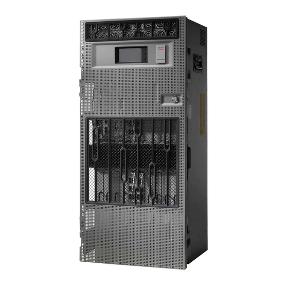
- Page 3 About the Cisco NCS 4016 and Cisco NCS 4009 Chassis The Cisco NCS 4016 chassis contains an upper card cage and a lower card cage, where the Route Processor Cards (RP), Line Cards (LC) and Fabric Cards (FC) are installed. The Cisco NCS 4009 chassis contains a single card cage where the RPs and LCs are installed.
- Page 4 The chassis contains its own power and cooling systems. Power systems are available using AC or DC power. Cisco NCS 4016 has two fan trays located in the top and bottom slots of the chassis. NCS 4009 has one fan tray located in the top slot of the chassis.
- Page 5 Chassis Overview About the Cisco NCS 4016 and Cisco NCS 4009 Chassis External connection unit (ECU) Card cages (2) each containing: • Craft panel is attached on top of the ECU • Eight LC slots - LC0 to LC7; LC8 to LC15 •...
- Page 6 Craft Panel The craft panel can install, configure, monitor, and troubleshoot the chassis applications at the node and at the network level. The craft panel is located on top of the ECU. Hardware Installation Guide for the Cisco NCS 4000 Series...
- Page 7 • Do not wear loose clothing, jewelry, and other items that could get caught in the chassis while working with the chassis and its components. • Use Cisco equipment in accordance with its specifications and product-usage instructions. • Do not work alone if potentially hazardous conditions exist.
- Page 8 Two ESD jacks are provided, one at the top of the chassis and one at the bottom of the chassis. Figure 3: ESD Jacks Top of Chassis Top ETSI connection point Top ANSI jacket point Hardware Installation Guide for the Cisco NCS 4000 Series...
- Page 9 Note To install two Cisco NCS 4016 chassis in a single rack, you will need to have a minimum vertical opening of 48 RU. If you are using the DC Power Front Connection Adapter, only one chassis will fit into the rack.
- Page 10 Figure 4: Single NCS 4016 Chassis Mounted in Rack Before you move the chassis or mount the chassis into the rack, we recommend that you do the following: Hardware Installation Guide for the Cisco NCS 4000 Series...
- Page 11 To attach the mounting brackets, simply fix each bracket onto the chassis using screws as shown in the figure, below. Tighten the screws to a torque value of 11.5 in-lb (1.3 N-m). Hardware Installation Guide for the Cisco NCS 4000 Series...
- Page 12 Mounting the Chassis Installing the Mounting Brackets Figure 5: Attaching Chassis Mounting Brackets in NCS 4009 Hardware Installation Guide for the Cisco NCS 4000 Series...
- Page 13 Mounting the Chassis Installing the Mounting Brackets Figure 6: Attaching Chassis Mounting Brackets in NCS 4016 Various types of bracket installation are shown in these illustrations: Hardware Installation Guide for the Cisco NCS 4000 Series...
- Page 14 Mounting the Chassis Installing the Mounting Brackets Figure 7: Attaching ANSI 19-Inch Brackets to Front (4-Post Rack) or Middle (2-Post Rack) in NCS 4009 Hardware Installation Guide for the Cisco NCS 4000 Series...
- Page 15 Mounting the Chassis Installing the Mounting Brackets Figure 8: Attaching ANSI 19-Inch Brackets to Front (4-Post Rack) or Middle (2-Post Rack) in NCS 4016 Hardware Installation Guide for the Cisco NCS 4000 Series...
- Page 16 Mounting the Chassis Installing the Mounting Brackets Figure 9: Attaching ANSI 23-Inch Brackets to Front (4-Post Rack) or Middle (2-Post Rack) in NCS 4009 Hardware Installation Guide for the Cisco NCS 4000 Series...
- Page 17 Mounting the Chassis Installing the Mounting Brackets Figure 10: Attaching ANSI 23-Inch Brackets to Front (4-Post Rack) or Middle (2-Post Rack) in NCS 4016 Hardware Installation Guide for the Cisco NCS 4000 Series...
- Page 18 Mounting the Chassis Installing the Mounting Brackets Figure 11: Attaching ETSI Brackets to Front in NCS 4009 Figure 12: Attaching ETSI Brackets to Front in NCS 4016 Hardware Installation Guide for the Cisco NCS 4000 Series...
- Page 19 • Cisco NCS 4009 installation kit (NCS4009-INST-KIT=) Steps Procedure Step 1 Attach the aid brackets to the rack below where the chassis will sit. Tighten the two screws to firmly attach the brackets to the rack. Hardware Installation Guide for the Cisco NCS 4000 Series...
- Page 20 By using the corresponding mounting hole (in the same hole group) on the opposite side of the rack, you can keep both the aid brackets leveled. Hardware Installation Guide for the Cisco NCS 4000 Series...
- Page 21 • NCS 4009 front door: (Cisco PID NCS4009-DOOR=) Steps Procedure Step 1 Turn the knob to unlock the door. Step 2 Open the door. Step 3 Loosen the screw to disconnect the ground cable. Hardware Installation Guide for the Cisco NCS 4000 Series...
- Page 22 Mounting the Chassis Removing and Replacing the Chassis Door Figure 14: Disconnecting the Ground Cable in NCS 4009 Hardware Installation Guide for the Cisco NCS 4000 Series...
- Page 23 Mounting the Chassis Removing and Replacing the Chassis Door Figure 15: Disconnecting the Ground Cable in NCS 4016 Step 4 Move down the pin to release the door from the chassis hinge. Hardware Installation Guide for the Cisco NCS 4000 Series...
- Page 24 Figure 17: Releasing the Bottom Hinge Pin Step 6 To replace the front door after the chassis is mounted on the rack: a) Remove the screw and washer from the chassis fixing point. Hardware Installation Guide for the Cisco NCS 4000 Series...
- Page 25 Using a Phillips screwdriver, insert and tighten the screws to a torque value of 11.5 in-lb (1.3 N-m). Figure 19: NCS 4009 with Door Ground Strap Retrofit Kit Installed (ANSI) Hardware Installation Guide for the Cisco NCS 4000 Series...
- Page 26 Swing the door closed and turn the knob to lock. Mounting the Chassis into a Rack This section describes how to mount the chassis into a rack. The figure below, shows the chassis mounting hardware ready for rack mounting. Hardware Installation Guide for the Cisco NCS 4000 Series...
- Page 27 • Number 2 Phillips screwdriver • Mechanical lifting device, such as a scissor lift or other suitable lifting device • NCS 4016 installation kit, shipped with the chassis, contains installation aid brackets and screws (Cisco PID NCS4K-INST-KIT=) Hardware Installation Guide for the Cisco NCS 4000 Series...
- Page 28 Mounting the Chassis Mounting the Chassis into a Rack • NCS 4009 installation kit, shipped with the chassis, contains installation aid brackets and screws (Cisco PID NCS4009-INST-KIT=) Steps To mount the chassis in the rack, follow these steps: Procedure Step 1 With the chassis on the lift, align the chassis with the rack.
- Page 29 Mounting the Chassis Mounting the Chassis into a Rack Figure 23: Chassis Mounting Holes Hardware Installation Guide for the Cisco NCS 4000 Series...
- Page 30 Use the corresponding mounting hole (in the same hole group) on the opposite side of the chassis to level the chassis in the rack. Step 7 Use the screwdriver to fully tighten the screws. Tighten the screws to a torque value of 22 in-lb (2.5 N-m). Hardware Installation Guide for the Cisco NCS 4000 Series...
-
Page 31: Table Of Contents
This chapter provides instructions on how to install route processor (RP) cards, fabric cards (FCs), line cards (LCs) and their associated components in the chassis. Note Unless otherwise specified, "chassis" refers to both Cisco NCS 4016 chassis and Cisco NCS 4009 chassis. • Preventing Electrostatic Discharge, on page 29 •... -
Page 32: Guidelines For Installing And Removing A Card
OIR is seamless to users on the network, maintains all routing information, and ensures session preservation. You do not need to notify the software or reset the power. You have the option of using the Cisco IOS XR shutdown command before removing a card. Note OIR removes power to a specific slot before the card is replaced. - Page 33 • In NCS 4016, if you are installing the card in the top rack, the arrow should be pointing up. If you are installing the card in the bottom rack, the arrow should be pointing down. • In NCS 4009, the arrow on the faceplate should be pointing up. Hardware Installation Guide for the Cisco NCS 4000 Series...
-
Page 34: About Rp Cards
LEDs on the front panel indicate active alarm conditions. Two RPs per chassis are required for a redundant system. RP cards are inserted into the two dedicated slots (RP0 and RP1) in the chassis. The RP cards are hot-swappable. Hardware Installation Guide for the Cisco NCS 4000 Series... -
Page 35: About Fabric Cards
NCS4016-FC-M (200G) NCS4016-FC2-M (400G) An Auxiliary Fan Tray (Cisco PID NCS4009-FAN-FC) is attached to the NCS4009-FC2F-S fabric card in the front. The Auxiliary Fan Tray (AFT) and the fan tray present in the front of the chassis (behind the craft panel), provide cooling for the chassis components. -
Page 36: About Line Cards
• 2-Port 100Gbps and 10-Port 10Gbps OTN and Packet (NCS4K-2H10T-OP-KS) Line Card - See datasheet https://www.cisco.com/c/en/us/products/collateral/optical-networking/ network-convergence-system-4000-series/datasheet-c78-736604.html. • 24-Port Low-Rate OTN (NCS4K-24LR-O-S) Line Card - See datasheet at https://www.cisco.com/c/en/ us/products/collateral/optical-networking/network-convergence-system-4000-series/data_sheet_ c78-729398.html. • 20-Port 10GE OTN (NCS4K-20T-O-S) Line Card - See datasheet at https://www.cisco.com/c/en/us/ products/collateral/optical-networking/network-convergence-system-4000-series/data_sheet_ c78-729398.html. Hardware Installation Guide for the Cisco NCS 4000 Series... -
Page 37: Installing A Route Processor, Fabric Card, Or Line Card
• Route processor (RP): Cisco PID NCS4K-RP • Fabric card (FC) in NCS 4016 : Cisco PID: NCS4016-FC-M or NCS4016-FC2-M • Fabric card (FC) in NCS 4009: Cisco PID: NCS4009-FC-S or NCS4009-FC2-S or NCS4009-FC2F-S Note The FC in NCS 4009 contains only one ejector lever and one captive screw. - Page 38 Installing Route Processor Cards, Fabric Cards, and Line Cards Installing a Route Processor, Fabric Card, or Line Card The following steps describe how to install a card. Figure 26: Installing a RP Card in NCS 4009 Hardware Installation Guide for the Cisco NCS 4000 Series...
- Page 39 Installing Route Processor Cards, Fabric Cards, and Line Cards Installing a Route Processor, Fabric Card, or Line Card Figure 27: Installing a RP Card in NCS 4016 Direction of insertion Captive screws Ejector levers OIR buttons Hardware Installation Guide for the Cisco NCS 4000 Series...
- Page 40 Installing Route Processor Cards, Fabric Cards, and Line Cards Installing a Route Processor, Fabric Card, or Line Card Figure 28: Installing a FC in NCS 4009 (NCS4009-FC2-S) Hardware Installation Guide for the Cisco NCS 4000 Series...
- Page 41 Installing Route Processor Cards, Fabric Cards, and Line Cards Installing a Route Processor, Fabric Card, or Line Card Figure 29: Installing a FC in NCS 4009 (NCS4009-FC2F-S) Hardware Installation Guide for the Cisco NCS 4000 Series...
- Page 42 Installing Route Processor Cards, Fabric Cards, and Line Cards Installing a Route Processor, Fabric Card, or Line Card Figure 30: Installing a FC in NCS 4016 Hardware Installation Guide for the Cisco NCS 4000 Series...
- Page 43 Installing Route Processor Cards, Fabric Cards, and Line Cards Installing a Route Processor, Fabric Card, or Line Card Figure 31: Installing a LC in NCS 4009 Hardware Installation Guide for the Cisco NCS 4000 Series...
- Page 44 • If you are inserting the RP or LC into the card cage of NCS 4009 or the upper card cage in NCS 4016, the arrows on the OIR buttons should be facing up. To orient the FC card in FC slots of NCS 4009, the ejector button should be facing down. Note Hardware Installation Guide for the Cisco NCS 4000 Series...
- Page 45 NCS 4016 or in NCS 4009. The dark gray arm should be facing up and the light gray arm should be facing down in the lower card cage of NCS 4016. See the following figure. Hardware Installation Guide for the Cisco NCS 4000 Series...
- Page 46 The connector on the fabric card holds the AFT firmly to the card. Step 12 Push the sliding handle to its original position. Step 13 Tighten the screws on the AFT using 5.75 pound/force (lbf) inch (0.65 Nm torque). Hardware Installation Guide for the Cisco NCS 4000 Series...
- Page 47 The NCS4009-FC2-S fabric card supports Cisco PID NCS4009-FTF. The NCS4009-FC2F-S fabric card supports Cisco PID NCS4009-FTF-2. Prerequisites Before performing this task, open the front door. Tools and Equipment • ESD-preventive wrist strap • Number-2 Phillips screwdriver Hardware Installation Guide for the Cisco NCS 4000 Series...
-
Page 48: Troubleshooting The Rp, Fc, Or Lc Card
• Ensure that the ejector levers are latched and that the captive screws are fastened properly. If you are uncertain, unlatch the levers, loosen the screws fully, and attempt to reseat the card. Hardware Installation Guide for the Cisco NCS 4000 Series... -
Page 49: Connecting Line Card Network Interface Cables
Note For cable connection information for your specific line card, refer to the installation and configuration note for that line card. You can access the most current Cisco line card documentation online at: http://www.cisco.com. Steps... - Page 50 Always allow adequate strain relief in the interface cable. Hardware Installation Guide for the Cisco NCS 4000 Series...
-
Page 51: Connecting Cables To The Rp
The ports labeled Ethernet and Console are safety extra-low voltage (SELV) circuits. SELV circuits should be connected only to other SELV circuits. Note RP cables are not available from Cisco, but they are available from any commercial cable vendor. Note To comply with the intra-building lightning surge requirements of Telecordia GR-1089-CORE, Issue 6, you must use a shielded cable when connecting to the console and Ethernet ports. - Page 52 Ethernet management ports are primarily used as Telnet ports into the chassis; they are also used for booting or accessing Cisco software images over a network to which an Ethernet port is directly connected. We strongly caution you to consider the security implications of enabling routing functions on these ports.
- Page 53 The chassis ships with power trays and power modules installed. Note Unless otherwise specified, “chassis” refers to both Cisco NCS 4016 chassis and Cisco NCS 4009 chassis. • Installing Power Components, on page 51...
- Page 54 The Short Circuit Protection Breaker shall not be rated more than 60A. Power redundancy requirements vary based on the system configuration (number and type of line cards, etc.). DC-powered systems are N+1 protected. Hardware Installation Guide for the Cisco NCS 4000 Series...
- Page 55 For DC power cables, we recommend 6 AWG high-strand-count copper wire cables, rated 75°C minimum. The size of the cables depends on your chassis location from the source power. Follow your local practices for determining cable size. DC power cables are not available from Cisco, but they are available from any commercial cable vendor.
- Page 56 • In the United States: United States National Fire Protection Association (NFPA) 70 and United States National Electrical Code (NEC). • In Canada: Canadian Electrical Code, part I, CSA C22.1. • In other countries: International Electrotechnical Commission (IEC) 60364, parts 1 through 7. Hardware Installation Guide for the Cisco NCS 4000 Series...
- Page 57 • Each AC power shelf contains four specific single phase AC inlet connectors. These connectors can accept four AC power cords provided by Cisco. AC power cords provided by Cisco can have a IEC-309 plug 32A rated for International power systems, or a NEMA L6-30P plug 30A rated for North America Power Systems.
- Page 58 AC power modules. Figure 40: NEBS Bonding and Grounding Points on NCS 4016 NEBS grounding point on front of chassis Hardware Installation Guide for the Cisco NCS 4000 Series...
- Page 59 Installing Power Components NEBS Supplemental Unit Bonding and Grounding Guidelines NEBS grounding point on right side of the Screws chassis Lock washers Hardware Installation Guide for the Cisco NCS 4000 Series...
- Page 60 4-AWG or larger, multistrand copper wire. This lug (part of the kit) is similar to those used for the DC input power supply leads. • Two M6 round-head screws and two locking washers (nickel-plated brass is ideal). Hardware Installation Guide for the Cisco NCS 4000 Series...
- Page 61 • One grounding wire. Although we recommend at least 4-AWG multistrand copper wire, the wire diameter and length depend on your chassis location and site environment. Note These parts are not available from Cisco (with the exception of the grounding lug), but they are available from commercial vendors. Installing the Chassis Ground Cable This section describes how to install a ground cable to either NEBS bonding and grounding point on the front or side of the chassis.
- Page 62 Use the torque-driver to attach the lug and ground cable to either grounding point . Note The two grounding point screws are required for proper bonding and grounding of the chassis and should not be removed. Hardware Installation Guide for the Cisco NCS 4000 Series...
- Page 63 Figure 43: Attaching to Front NEBS Bonding and Grounding Point in the NCS 4016 Screws Lock washers Figure 44: Attaching to Side NEBS Bonding and Grounding Point in the NCS 4016 NEBS grounding point on right side of the Screws chassis Lock washers Hardware Installation Guide for the Cisco NCS 4000 Series...
- Page 64 The power tray is preinstalled on the chassis. The following procedure describes how to install an AC or DC power tray in the chassis. Tools and Equipment • 6-inch, number-2 Phillips screwdriver Hardware Installation Guide for the Cisco NCS 4000 Series...
- Page 65 • On: An internal fault is detected within the power module. • Off: No internal faults detected on the power module. Installing AC or DC Power Modules The following section describes how to install AC or DC power modules. Hardware Installation Guide for the Cisco NCS 4000 Series...
- Page 66 Remove the filler caps from the slots where you want to install the power modules. Step 2 Using two hands to support the power module, slide it into the power tray. Hardware Installation Guide for the Cisco NCS 4000 Series...
- Page 67 Installing Power Components Installing AC or DC Power Modules Figure 46: Example of Inserting the AC Power Module in the NCS 4016 Hardware Installation Guide for the Cisco NCS 4000 Series...
- Page 68 Power Front Connection Adapter. This DC adapter moves the DC power connections from the back of the chassis to the front of the chassis. This may be desirable in ETSI rack installations. Hardware Installation Guide for the Cisco NCS 4000 Series...
- Page 69 Install the DC-FA (front access) brackets on the sides toward the front of the DC adapter. There are three different types of bracket depending upon rack type: ANSI 19 inch or 23 inch and ETSI. Choose the correct type for your specific rack. Hardware Installation Guide for the Cisco NCS 4000 Series...
- Page 70 Figure 49: Installing the DC-FA Brackets Step 2 Attach the rear cable guide on top of the chassis toward the rear, and attach the insulator sheet on top of the chassis toward the front . Hardware Installation Guide for the Cisco NCS 4000 Series...
- Page 71 Figure 50: Attaching Rear Cable Guide and Insulator Sheet Rear cable guide Insulator sheet Step 3 Place the DC adapter on top of the chassis using the embossed references on the top chassis cover. Hardware Installation Guide for the Cisco NCS 4000 Series...
- Page 72 Connect the power cables on the rear of the of DC adapter to the chassis terminal blocks. Follow the connections scheme as shown on the labels available on the DC adapter and the chassis. Hardware Installation Guide for the Cisco NCS 4000 Series...
- Page 73 Install the rear cover to protect the cables. Step 6 Install the chassis and DC adapter subassembly in the rack or cabinet. Attach the chassis brackets and DC brackets to the rack. Hardware Installation Guide for the Cisco NCS 4000 Series...
- Page 74 Connect the power cables coming from batteries or from the PDU unit to the DC adapter terminal blocks on the front side of the unit . See the Connecting Power to the Chassis, on page Hardware Installation Guide for the Cisco NCS 4000 Series...
- Page 75 Follow these steps to connect the AC power cords to the chassis. Note Connect each AC power supply to a dedicated power source (branch circuit). Each AC input power supply operates at a nominal input level of 200 to 240 VAC. Hardware Installation Guide for the Cisco NCS 4000 Series...
- Page 76 • In some cases, the source DC cable leads might have a positive (+) or a negative (–) label. This is a relatively safe indication of the polarity, but you must verify the polarity by measuring the voltage between Hardware Installation Guide for the Cisco NCS 4000 Series...
- Page 77 Do not over tighten the nuts that secure the DC power cables to the power tray terminals. The nuts should be tightened using the 7/16 hex socket and torque wrench to a torque of 45 to 50 in-lb. Hardware Installation Guide for the Cisco NCS 4000 Series...
- Page 78 Figure 56: DC Power Tray Rear Panel Figure 57: Typical Power Connections to a Power Tray for a Single DC Power Module Power System Step 6 Replace the clear plastic safety covers over the connection terminal studs. Hardware Installation Guide for the Cisco NCS 4000 Series...
- Page 79 Installing Power Components Connecting Power to a DC-Powered Chassis Figure 58: Typical Plastic Safety Covers over the Power Tray Connection Terminals Step 7 Proceed to the Powering On the Chassis, on page Hardware Installation Guide for the Cisco NCS 4000 Series...
- Page 80 Set the power tray switch to the OFF (0) postion to disconnect all power from the DC chassis and also power off the circuit breaker. If you are disconnecting power to one of the power trays, power off the circuit breaker assigned to the DC power. Hardware Installation Guide for the Cisco NCS 4000 Series...
- Page 81 Verify that the Power Output LED on each power module in the tray is lit. Step 5 Repeat Step 3 and Step 4 for power tray 1 (Feed B in case of AC chassis). Hardware Installation Guide for the Cisco NCS 4000 Series...
- Page 82 Installing Power Components Powering On the Chassis Hardware Installation Guide for the Cisco NCS 4000 Series...
Need help?
Do you have a question about the NCS 4000 Series and is the answer not in the manual?
Questions and answers