Table of Contents
Advertisement
Quick Links
Advertisement
Chapters
Table of Contents

Related Manuals for Dräger Oxylog 2000 plu


Summary of Contents for Dräger Oxylog 2000 plu
-
Page 1: Instructions For Use
Instructions for Use Oxylog 2000 plus Emergency and Transport Ventilator WARNING For a full understanding of the perfor- Software 1.n mance characteristics of this device, the user should carefully read this man- ual before use of the device. - Page 2 Working with these Instructions for Use Working with these Instructions for Use The title of the main chapter in the header line Trademarks helps with orientation and navigation. ® The Dräger Oxylog name is a registered trade- The Instructions for Use combine text and illustra- mark of Dräger.
-
Page 3: Table Of Contents
Contents Contents For Your Safety and that of Your Patients . Preparing ventilation mode ....VC-CMV / VC-AC ..... General WARNINGS and CAUTIONS . - Page 4 Contents Disposal of the medical device ... . 100 Disposal of the disposable hose system ..101 Technical Data ..... . . 103 Ambient conditions .
-
Page 5: For Your Safety And That Of Your Patients
For Your Safety and that of Your Patients For Your Safety and that of Your Patients Strictly follow these Instructions for Use Accessories WARNING WARNING Any use of the medical device requires full Only the accessories indicated on the list of understanding and strict observation of all accessories have been tested and approved portions of these Instructions for Use. -
Page 6: Patient Safety
For Your Safety and that of Your Patients Patient safety Functional safety The design of the medical device, the accompany- The essential performance of the Oxylog 2000 plus ing literature, and the labeling on the medical is defined as: device are based on the assumption that the pur- Accuracy of the delivery of ventilation to the patient chase and use of the equipment are restricted to or generation of a technical alarm condition. -
Page 7: General Warnings And Cautions
For Your Safety and that of Your Patients General WARNINGS and CAUTIONS The following WARNINGS and CAUTIONS apply to WARNING general operation of the device. WARNINGS and Keep a manual resuscitation bag available! CAUTIONS specific to subsystems or particular features appear with those topics in later sections If a failure is detected in the ventilator and its of the manual. - Page 8 For Your Safety and that of Your Patients Instructions for Use only available once CAUTION Only one copy of the Instructions for Use is included in the clinical package and should there- fore be kept in an accessible location for users. Instructions for Use Oxylog 2000 plus SW 1.n...
-
Page 9: Application
Application Application Intended use ......Indications/Contraindications ... Environment of use . -
Page 10: Intended Use
Application Intended use ® The Oxylog 2000 plus is a time-cycled, volume controlled emergency and transport ventilator with pressure support for patients requiring mandatory or assisted ventilation with a tidal volume of 100 mL upwards. For use by and under the supervision of trained health care professionals. -
Page 11: System Overview
System Overview System Overview Front panel with all options... . . Side view, right ......Rear view . -
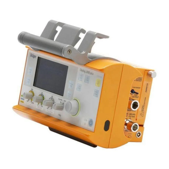
Page 12: Front Panel With All Options
System Overview Front panel with all options A Screen with screen pages for the specific K Display symbols for the power supply application Charge status of the internal battery Mains power supply connected B Key Alarms for setting and displaying alarm limits L Central rotary knob for making selections / settings and for confirming these... -
Page 13: Side View, Right
System Overview Side view, right Rear view A Emergency air intake A Filter cartridge for intake of ambient air WARNING CAUTION Do not block the emergency air intake. This Do not block the air intake. This may result in may result in ventilator malfunction. ventilator malfunction. -
Page 14: Reusable Hose System
System Overview Reusable hose system Disposable hose system A Breathing valve A Breathing valve B Ventilation hose B Ventilation hose C Flow and pressure measuring hoses C Flow and pressure measuring hoses D Angled connector D Flow sensor E Flow sensor E Angled connector Available ventilation modes –... -
Page 15: Special Modes
System Overview Special modes In the ventilation mode SpnCPAP, two special modes are available. – Apnea Ventilation To switch over automatically to volume-con- trolled mandatory ventilation if spontaneous breathing stops. – NIV For mask ventilation to support non-invasive ventilation of spontaneously breathing patients with leakage compensation. -
Page 16: Abbreviations
System Overview Abbreviations Abbreviation Explanation Abbreviation Explanation Pressure Support, pressure assisted Breaths per minute spontaneous breathing BTPS Body Temperature, Pressure Radio Frequency Saturated Respiratory Rate (frequency) Measured values referred to the con- RRapn Respiratory Rate during apnea ditions of the patient's lung, body ventilation temperature 37 C, airway pressure,... -
Page 17: Symbols
System Overview Symbols Symbol Explanation Symbol Explanation The device complies with UN 10 R-02 XXXX Display screen window "Settings" Settings Regulation no. 10, revision 2 with respect to EMC for use in motor vehicles. Display screen window "Alarms" Alarms IPX4 Device protected from water sprayed from all directions, limited entrance allowed. - Page 18 This page intentionally left blank Instructions for Use Oxylog 2000 plus SW 1.n...
-
Page 19: Operating Concept
Operating Concept Operating Concept Switch ON or OFF..... Switch ON......Switch OFF. -
Page 20: Switch On Or Off
Operating Concept Switch ON or OFF Oxylog 2000 plus Switch ON To switch ON, briefly press the key (A). Switch OFF 1 To switch OFF, hold down the key (A) for approximately 3 seconds. 2 Press the rotary knob (B) to confirm the switch OFF process. -
Page 21: Ventilation Controls
Operating Concept Ventilation controls Selecting the ventilation mode Oxylog 2000 plus Oxylog 2000 plus A Keys for selecting the ventilation modes: Press the appropriate ventilation mode key (A) – VC-CMV / VC-AC for approximately 3 seconds. – VC-SIMV (optional PS) –... -
Page 22: Display Operating Controls
Operating Concept Routine and additional functions keys key for suppressing the audible alarm for 2 minutes. Frequently used keys are positioned on the upper right corner of the front panel: B Alarm Reset key for acknowledging alarm messages. Oxylog 2000 plus Display operating controls A Values key;... -
Page 23: Changing Screen Pages In The Windows
Operating Concept Changing screen pages in the windows To advance to the next page in a screen window: Settings and Alarms window: 1 Press the Settings key to display the settings pages. 2 Press the Alarms key to display the alarms pages. - Page 24 Operating Concept MVe / VTe window To advance to the next page: Press the lower Values key. Airway pressure bar graph A Parameter measured. B Measured value. C Unit of measure. A Pmax alarm setting. D Page number. B Unit of measure scale. C Pressure measurement of the previous breath.
- Page 25 Operating Concept To advance to the next page: Messages window Press the Alarms key. Settings window A Numeric values displayed when a control knob is turned. A Menu for setting supplementary ventilation parameters in accordance with the desired ven- tilation mode: –...
- Page 26 Operating Concept Battery capacity indicator A Battery capacity indicator (example: three quar- ters full). consumption A Actual gas consumption based on current settings. Instructions for Use Oxylog 2000 plus SW 1.n...
-
Page 27: Assembly
Assembly Assembly Dead space ......Assemble the reusable hose system ..Breathing valve assembly. -
Page 28: Dead Space
Assembly Reusable or disposable hose systems can be used with Oxylog 2000 plus. Please refer to the "List of Accessories" section for ordering information. NOTE If the type of the hose system used is changed, the device must be reconfigured. Refer to the "Configuration"... -
Page 29: Assemble The Reusable Hose System
Assembly Assemble the reusable hose system – Parts must always be sterilized before use! Breathing valve assembly WARNING The rubber disc (A) in the housing may not be removed, damaged or bent, otherwise the valve will not work properly and will endanger the patient. -
Page 30: When Using A Bacterial Filter Or Hme
Assembly When using a bacterial filter or HME CAUTION NOTE Do not use electrically conductive hoses! When using a bacterial filter or HME, measured Risk of electric shock. flows may deviate from the expiratory flows, as This can endanger the patient. temperature and humidity of the gas are reduced. -
Page 31: Connect The Disposable Hose System
Assembly Connect the disposable hose system When using a bacterial filter or HME WARNING NOTE Do not use disposable hose systems other than those on the "List of Accessories". The When using a bacterial filter or HME, measured minute volume may be measured incorrectly flows may deviate from the expiratory flows, as and the device may malfunction. -
Page 32: Connecting The Power Supply
Assembly Connecting the power supply The Oxylog 2000 plus is designed to operate on – with AC/DC power pack power supplies with different voltages. WARNING A fully charged battery must always be Internal supply installed for safety reasons, even when oper- ating from an external power supply! –... -
Page 33: Installing The Battery
Assembly Installing the battery 1 Insert a fully charged battery into the battery compartment. 2 Attach the connector at the bottom. 12 V DC 24 V DC 3 Turn the cover upwards. 28 V DC Oxylog 2000 plus 4 Tighten the screw. WARNING The Oxylog 2000 plus will interrupt ventilation when the battery is replaced while the device... -
Page 34: Connecting The Gas Supply
Assembly 1 Connect the mains plug (A) to the mains outlet. 2 Connect the DC plug (B) to the DC outlet on the Oxylog 2000 plus. 3 When the Oxylog 2000 plus is connected to an O xylog 2000 plus external supply, the indicator (C) lights up and displays the internal battery status. -
Page 35: Supply From An O2 Cylinder
Assembly Supply from an O cylinder 5 Rotate the cylinder valve (C) slowly and open fully. WARNING Only use compressed gas cylinders and pres- CAUTION sure reducers, which comply with all applicable Do not connect flow control valves or flowmeters regulations and have been approved. -
Page 36: Hanging The Oxylog 2000 Plus On Standard Rail Systems
Assembly Hanging the Oxylog 2000 plus on standard rail systems The Oxylog 2000 plus can be hung on various rail systems measuring up to 35 mm diameter by means of the claw. – Ensure that the rail is completely inserted in the claw. -
Page 37: Getting Started
Getting Started Getting Started Charging the battery ....Indication of battery capacity / battery operation 38 Determining the approximate pneumatic oper- ating time for the Oxylog 2000 plus ..Checking readiness for operation . -
Page 38: Charging The Battery
Getting Started Charging the battery Indication of battery capacity / battery The actual screen display may differ in appearance or configuration. operation CAUTION The ambient temperature must be between 0 and 35 C when charging the batteries. When an external supply is available: Oxylog 2000 plus The remaining capacity of the battery is indicated by Oxylog 2000 plus in 25% increments in the lower... -
Page 39: Determining The Approximate Pneumatic Operating Time For The Oxylog 2000 Plus
Getting Started Determining the approximate pneumatic operating time for the Oxylog 2000 plus Example for supply of medical gas: Example: – Cylinder pressure measured on the pressure gauge of the pressure reducer: 2000 kPa – Liquid capacity of the O cylinder: 2.1 L Supply of medical gas: 2.1 L x 2000 kPa = approximately 420 L... -
Page 40: Checking Readiness For Operation
Getting Started Checking readiness for operation – Whenever the ventilator has been serviced or the ventilation hoses changed. – At the latest every six months. The following functions are checked with the menu- based test: – Gas supply present. – Hose system / breathing valve connected and –... -
Page 41: Perform Device Check
Getting Started Perform device check The device check consists of the following steps. Switch ON – Duration is approximately 3 minutes. Connect the test lung Oxylog 2000 plus 1 To switch ON briefly press the key (B). The device performs a self-test and the operator is prompted, on the display, to activate the configuration menu or device check: Press rotary knob for device check and... -
Page 42: Check Connections
Getting Started Check connections System check 1 Ensure that the gas supply has been connected. 2 Ensure that the test lung has been connected. The Oxylog 2000 plus automatically checks if a test lung has been connected. The device check is Oxylog 2000 plus aborted if a test lung is not detected within one minute. -
Page 43: Troubleshooting
Getting Started Troubleshooting 3 Contact your local DrägerService for support. WARNING The ventilator is ready for operation only after all functional tests have been successfully per- formed. If the device check is not completed successfully: 1 Refer to "Error messages during the device check"... - Page 44 This page intentionally left blank Instructions for Use Oxylog 2000 plus SW 1.n...
-
Page 45: Operation
Operation Operation Starting operation..... Switch ON......Preparing ventilation mode . -
Page 46: Starting Operation
Operation Starting operation The actual screen display may differ in appearance or configuration. WARNING Only use a ventilator that has been cleaned and successfully tested for operation, to pre- vent a health risk for the patient and user. Switch ON Upon completion of the self-test, the ventilator automatically begins ventilation with the default settings. -
Page 47: Preparing Ventilation Mode
Operation Preparing ventilation mode To activate the ventilation mode 1 Press and hold the ventilation mode key for approximately 3 seconds. 2 Press the ventilation mode key and confirm by pressing the rotary knob. The new ventilation mode selected is now effective. Set ventilation parameters 1 Set the required control below the display. -
Page 48: Vc-Cmv / Vc-Ac
Operation VC-CMV / VC-AC The following can be set on the display: Plateau time Tplat plat PEEP insp Flow – Positive end expiratory pressure PEEP. Insp. Flow – Ventilation time ratio I:E. – Plateau time Tplat %, in % of the inspiration time. -
Page 49: Trigger (Vc-Ac)
Operation Trigger (VC-AC) Activating/setting the trigger NOTE If in VC-CMV the trigger is set »on«, the ventilation mode changes into VC-AC. Refer to the previous section. VC-AC – Volume Controlled - Assist Control Oxylog 2000 plus For synchronisation with the patient's spontaneous breathing efforts. -
Page 50: Vc-Simv (Optional Ps)
Operation VC-SIMV (optional PS) The following are set on the display: Pressure support PS rapid slow rise time rise time PEEP Trigger window Flow – Inspiration time Ti. Insp. Flow – Plateau time Tplat %, in % of the inspiration time. -
Page 51: Pressure Support (Optional)
Operation Pressure support (optional) The following can also be set on the display for VC-SIMV / PS: ∆ – Setting on page 1: Pressure support Psupp above PEEP. – Setting on page 2: Pressure rise time Slope steep slope = short pressure rise time flat slope = long pressure rise time. -
Page 52: Spncpap (Optional Ps)
Operation SpnCPAP (optional PS) Apnea back-up ventilation is only applicable when using the SpnCPAP mode. In the event of an Continuous Positive Airway Pressure apnea, the ventilator will automatically activate WARNING volume-controlled mandatory ventilation Only use SpnCPAP for patients with sufficient (VC-CMV). -
Page 53: Pressure Support (Optional)
Operation Pressure support (optional) The parameters RRapn and VTapn, which are required for setting apnea ventilation, are now displayed: The following can additionally be set on the display for SpnCPAP / PS: 3 Set RRapn and VTapn. – Sensitivity Trigger (for synchronization with the 4 Set Pmax. -
Page 54: Niv - Non-Invasive Ventilation Mask Ventilation (Optional)
Operation NIV – Non-invasive ventilation – The supplement NIV appears in the upper section of the display. Mask ventilation (optional) NIV can only be activated as a supplementary function in the pressure-controlled ventilation modes SpnCPAP and SpnCPAP / PS. Mask leak- ages are detected by the device, compensated and included in the measured values for VTe and MVe. -
Page 55: O2 Airmix Or 100% O2
Operation AirMix or 100% O The FiO concentration can be set to O AirMix or 100% O , regardless of the ventilation mode. 2 (%) When set to O AirMix the injector principle of the Oxylog 2000 plus will draw in ambient air, to realize 85 (%) an FiO concentration of approximately 40%. -
Page 56: Calibration
Operation Calibration The pressure and flow sensors are automatically The saved calibration values are retained even calibrated by the device at regular intervals without when the device is switched OFF. interrupting ventilation. Screen brightness The screen brightness levels can be set on the last –... -
Page 57: Shutdown
Operation Shutdown – After disconnecting the patient Switch the ventilator OFF: Oxylog 2000 plus 1 Press the key (A) for approximately 3 seconds. The yellow lamp flashes and ventilation is terminated by the device. 2 Press the rotary knob (B) to acknowledge the alarm !!! Confirm device OFF with rotary knob. - Page 58 This page intentionally left blank Instructions for Use Oxylog 2000 plus SW 1.n...
-
Page 59: Alarms
Alarms Alarms Types of alarms ..... . In the event of an alarm ....Setting alarm limits . -
Page 60: Types Of Alarms
Alarms Types of alarms The actual screen display may differ in appearance Caution or configuration. An alarm of medium priority. The alarm LED (A) flashes yellow. Oxylog 2000 plus assigns a priority to the alarm Caution messages are highlighted by two exclama- message. -
Page 61: In The Event Of An Alarm
Alarms In the event of an alarm Oxylog 2000 plus Oxylog 2000 plus 1 Press the key (A). The LED (A) flashes red or yellow. The yellow LED lights up and all alarm tones are suppressed for approximately 2 minutes. The alarm message appears on the right of the Alarm tones are resumed by the device after status and alarm message window (C). - Page 62 Alarms In the event of a gas failure CAUTION In the event of a gas failure, the Oxylog 2000 plus cannot continue ventilation and issues the alarm !! Supply pressure low. Immediately start ventilating the patient with an independent manual ventilation device (resuscita- tion bag) using PEEP and/or increased inspiratory oxygen concentration where appropriate.
-
Page 63: Setting Alarm Limits
Alarms Setting alarm limits To set alarm limits for MV and RRsp CAUTION 2 Press the key Alarms (A). Set alarm values carefully. Display example Alarms screen with variable Extreme alarm values can render the alarm alarm limits. system useless. = lower alarm limit. - Page 64 Alarms Setting alarm limits automatically WARNING After using the function Auto alarm limits: check if the new alarm limits are appropriate for the patient. Risk of hypoventilation. The function Auto alarm limits sets the alarm limits on the basis of the following actual measured values at the time of activation: : Measured value MV +2 L/min : Measured value MV –2 L/min...
-
Page 65: Monitoring
Monitoring Monitoring Displaying the airway pressure..Displaying MVe and VTe ....Displaying O2 values ....Displaying other measured values . -
Page 66: Displaying The Airway Pressure
Monitoring Displaying the airway pressure The actual screen display may differ in appearance or configuration. The airway pressure is displayed in a bar graph indicator on the display. Refer to the "Operating concept" section on page 24 for additional information. Displaying MVe and VTe MVe and VTe are displayed in the measured MVe / To switch between the values:... -
Page 67: Displaying Other Measured Values
Monitoring Displaying other measured values Additional measured values are displayed in the measured values window. Refer to the "Operating concept" section on page 24 for additional information. To switch between the values: Press the lower Values key: the next value is displayed on the screen. In the values window five different values can be displayed. - Page 68 This page intentionally left blank Instructions for Use Oxylog 2000 plus SW 1.n...
-
Page 69: Configuration
Configuration Configuration Set configuration parameters / display informa- tion ....... . . Displaying configuration and information . -
Page 70: Set Configuration Parameters / Display Information
Configuration Set configuration parameters / display information The actual screen display may differ in appearance or configuration. 1 Switch the Oxylog 2000 plus ON. Press the key. The device performs a self-test and the operator is prompted to enter the configuration menu or device check: Press rotary knob for device check and con- figuration. -
Page 71: Displaying Configuration And Information
Configuration Displaying configuration and information – The settings made via the "Configuration" are 3 Select the language and confirm. retained after the ventilator is switched OFF. The new language selected is effective immediately. – Configuration can be cancelled by pressing the Alarm reset key or by startup of ventilation. -
Page 72: Customer Service Mode
Configuration Customer Service Mode WARNING Ventilation is not possible in customer service mode. In customer service mode, the ventilator performs function tests, outputs status information and permits configuration of parameter settings. Displays in customer service mode appear in Eng- lish and cannot be changed to any other language. Set startup settings. -
Page 73: To Enter Customer Service Mode
Configuration To enter customer service mode Settings in customer service mode 1 Select the required function with the cursor (asterisk). – To select the parameter: turn the rotary knob. – To activate the parameter: press the rotary Oxylog 2000 plus knob. -
Page 74: Set Startup Settings
Configuration Set startup settings Advance to the second page: Range of the settings: 1 Select the line Page, confirm and turn rotary Parameter Range knob. Trigger 0 (OFF) 3 to 15 L/min PEEP 0 to 20 mbar 3:1 to 1:4 0.2 to 10.0 s Tplat % 0 to 50%... - Page 75 Configuration Set date and time NOTE The date and time can be set. It is recommended that you have the O value as a displayed value. To define the five values to be displayed: Start configuration on page 1/5 and continue through to 5/5.
- Page 76 Configuration The selected test remains active until the rotary Set the controls accordingly for the test: knob is pressed again. – VT to 500 mL Display accu (battery) and supply data – RR to 20 /min The parameters of the replaceable battery and the –...
- Page 77 Configuration Display actual technical error Display settings logbook Momentarily active technical errors are displayed with the error number and a brief description. Display (example): The operating phases with ventilator settings and time are listed in chronological order. Advance to the next page: Display error and info logbook Select line Page, confirm and turn the rotary Any technical errors and/or special occurrences,...
-
Page 78: Exit Customer Service Mode
Configuration Exit customer service mode 1 Press the key for approximately 3 seconds; the LED flashes yellow. To switch ventilation ON: 2 Briefly press the key To switch OFF: 3 Press the rotary knob. Instructions for Use Oxylog 2000 plus SW 1.n... -
Page 79: Problem Solving
Problem Solving Problem Solving Alarm - Cause - Remedy ....Messages in the information window..Error messages during the device check . Instructions for Use Oxylog 2000 plus SW 1.n... -
Page 80: Alarm - Cause - Remedy
Problem Solving Alarm - Cause - Remedy Oxylog 2000 plus classifies alarm messages In the following table, the alarm messages are according to three priority levels and identifies listed in alphabetical order. If an alarm occurs, the these accordingly with the aid of exclamation table helps to identify causes and remedies. - Page 81 Problem Solving Alarm Cause Remedy Alarm Rank Check settings The expiration time result- Change RR or I:E or Ti. time ing from the settings for RR and I:E or Ti is not possible. Confirm device has been pressed To switch OFF: confirm. OFF with rotary for 3 seconds.
- Page 82 Problem Solving Alarm Cause Remedy Alarm Rank Leakage The measured expiratory Repair leaks in hose system and tidal volume VTe is approxi- possibly in the tube. Check place- (not in NIV) mately 40% lower than the ment of lower sentence. inspiratory value.
- Page 83 Problem Solving Alarm Cause Remedy Alarm Rank Paw high The alarm limit Pmax for the Check patient's condition, check airway pressure has been ventilation pattern, adjust alarm reached. Patient "fights" the limits if necessary. ventilator, coughing. Ventilation hose kinked, or Check hose system, breathing obstructed.
-
Page 84: Messages In The Information Window
Problem Solving Messages in the information window (Numerical examples) Message Cause Explanation/Remedy RR = 12 per min or Change in Ti, RR or VT in ventila- VT = 800 mL tion mode VC-SIMV. I : E = 1 : 1.5 Flow = 15 L/min RR = 12 per min or Change in I/E, RR or VT in ventila-... -
Page 85: Error Messages During The Device Check
Problem Solving Error messages during the device check Message Cause Explanation/Remedy No communication control- / Device defective Contact your local DrägerService charge-board for additional support. System leakage Leak in ventilation hose system Check hoses, breathing valve, and/or test lung. flow sensor and test lung for leaks and replace if necessary. - Page 86 This page intentionally left blank Instructions for Use Oxylog 2000 plus SW 1.n...
-
Page 87: Cleaning, Disinfection And Sterilization
Cleaning, Disinfection and Sterilization Cleaning, Disinfection and Sterilization Disassembly ......Disassemble the reusable hose system ..Remove the disposable hose system. -
Page 88: Disassembly
Cleaning, Disinfection and Sterilization Disassembly Disassemble the reusable hose system WARNING When disconnecting the ventilation hose, always grip the sleeve (A) and not the corruga- tions (B)! If this is not done, the corrugations or hose may be torn from the sleeve. 1 Disconnect the ventilation hose (A) from the gas output. - Page 89 Cleaning, Disinfection and Sterilization Breathing valve, disassembly 4 Disconnect the flow sensor (A) from the breath- 8 Turn the cover (A) about 90 ing valve. counterclockwise to unlock the cover. 9 Remove the silicone diaphragm (B). WARNING Do not twist or use force when disconnecting WARNING the flow measuring hoses from the flow sen- Do not disassemble breathing valve any fur-...
-
Page 90: Remove The Disposable Hose System
Cleaning, Disinfection and Sterilization WARNING The rubber disc (A) in the housing must not be removed, damaged or bent, otherwise the valve will not work properly and endangers the patient. Risk of CO rebreathing. Remove the disposable hose system 1 Disconnect flow measuring hoses (A and B). 2 Disconnect the ventilation hose (C). -
Page 91: Reprocessing Procedure
Cleaning, Disinfection and Sterilization Reprocessing procedure – Clean breathing valve, flow sensor, angled adapter and ventilation hoses of the reusable CAUTION hose system after use. Disinfectants based on: – Always exchange the disposable hose system – compounds containing alkylamine after use on a patient. –... -
Page 92: Sterilizing The Reusable Hose System
Cleaning, Disinfection and Sterilization Disinfecting by wiping Bath disinfection for reusable hose system Ventilator and medical gas hose: Disassembled parts of the breathing valve, flow sensor, ventilation hose and flow measuring hoses: – Follow the manufacturer's instructions. Remove heavy soiling with a disposable cloth first. WARNING WARNING Follow the manufacturer's instructions. -
Page 93: After Care
Cleaning, Disinfection and Sterilization – Sterilization for longer than 10 minutes is permissible, but will decrease the service life of the hose system. After care – Reassemble, refer to the "Assembly" section for information. – Connect to the power supply and gas supply, refer to the "Assembly"... - Page 94 This page intentionally left blank Instructions for Use Oxylog 2000 plus SW 1.n...
-
Page 95: Maintenance
Maintenance Maintenance Maintenance intervals ....In case of ventilator failure ....Instructions for Use Oxylog 2000 plus SW 1.n... -
Page 96: Maintenance Intervals
Maintenance Maintenance intervals Inspection examination of actual condition. Service measures to maintain specified condition. Repair measures to restore specified condition. Maintenance inspection, service, and repair, where necessary. Preventive maintenance measures at regular Maintenance intervals. CAUTION In order to avoid malfunctioning of the device, maintenance must be carried out by properly trained service personnel. - Page 97 Maintenance In case of ventilator failure CAUTION Never operate a ventilator if it has suffered physi- cal damage or does not seem to operate properly. In this case, always refer servicing to factory trained and authorized personnel. Instructions for Use Oxylog 2000 plus SW 1.n...
- Page 98 This page intentionally left blank Instructions for Use Oxylog 2000 plus SW 1.n...
-
Page 99: Disposal
Disposal Disposal Safety information ....100 Disposal of batteries ....100 Disposal of the medical device . -
Page 100: Disposal Of The Medical Device
Disposal Safety information For countries subject to the EU directive 2002/96/EC This device is subject to EU Directive 2002/96/EC (WEEE). In order to comply with its registration, according to this directive, it may not be disposed of at municipal collection points for electrical and electronic equipment waste. -
Page 101: Disposal Of The Disposable Hose System
Disposal Disposal of the disposable hose system Always follow local regulations governing the disposal of disposable hose systems according to established hospital/EMS procedures. Instructions for Use Oxylog 2000 plus SW 1.n... - Page 102 This page intentionally left blank Instructions for Use Oxylog 2000 plus SW 1.n...
-
Page 103: Technical Data
Technical Data Technical Data Ambient conditions ....104 During operation ..... . . 104 During storage and transportation . -
Page 104: Ambient Conditions
Technical Data WARNING Do not use the device outside the specified environmental and supply conditions, as the device may not operate according to its spec- ifications and may become inoperative. Ambient conditions During operation Temperature –20 to 50 Atmospheric pressure 570 to 1200 hPa Relative humidity 5 to 95%... -
Page 105: Settings
Technical Data Settings Ventilation modes VC-CMV, VC-AC, VC-SIMV, SpnCPAP, Optional: Pressure support for VC-SIMV and SpnCPAP. Ventilation frequency RR 2 to 50 /min ±1 /min (VC-SIMV) 5 to 50 /min ±1 /min (VC-CMV, VC-AC) 12 to 50 /min ±1 /min for apnea ventilation. Ventilation time ratio I:E (VC-CMV, VC-AC) 1:4 to 3:1 Inspiration time Ti (VC-SIMV, VC-SIMV / PS) -
Page 106: Performance Data
Technical Data Performance data Control principle Time-cycled, volume-constant, pressure supported. Maximum inspiratory flow 100 L/min Device compliance with 1.5 m ventilation hose< 1 mL/mbar with 3 m ventilation hose < 2 mL/mbar Inspiration resistance < 6 mbar at 60 L/min <... -
Page 107: Measured Value Display
Technical Data Measured value display Airway pressure measurement Range 0 to 99 mbar Resolution 1 mbar Accuracy ±2 mbar Maximum airway pressure Positive end expiratory pressure PEEP Mean airway pressure Pmean Plateau pressure Pplat Flow measurement Minute volume MVe Range 0 to 99 L/min, BTPS Resolution 0.1 L/min... -
Page 108: Monitoring
Technical Data Monitoring Expiratory minute volume MVe Alarm, upper alarm limit When the upper alarm limit has been exceeded. Range of settings 2 to 41 L/min Alarm, lower alarm limit When the level drops below the lower alarm limit. Range of settings 0.5 to 40 L/min Airway pressure Paw Alarm, upper alarm limit... -
Page 109: Operating Data
Technical Data Operating data Power supply Power supply Input voltage 19 V ±0.5 V DC Oxylog 2000 plus With DC/DC converter 12 / 24 / 28 V DC Current consumption With battery charge 2.1 A Operating time with fully charged internal battery approximately 4 hours without mains supply for "typical"... -
Page 110: Gas Supply
Technical Data AC/DC power pack Temperature range –20 C to 50 Protection class to Class II, the earthing is used for EMC purposes. EN 60601 Input 100 to 240 V~/ 50 to 60 Hz / 0.6 - 0.3 A Output 19 V ±0.5 V / 2.1 A DC/DC converter Temperature range... -
Page 111: Device Specifications
Technical Data Device specifications Noise pressure <45 dB (A) for typical ventilation at a distance of 1 m. Dimensions (W x H x D) Basic unit 285 x 184 x 175 mm (without handle) AC/DC power supply 161 x 63 x 118 mm DC/DC converter 162 x 42 x 69 mm Weight... -
Page 112: Materials Used
Technical Data Materials used Housing, Oxylog 2000 plus. Acrylonitrile styrene acrylate/polycarbonate (ASA/PC). Housing, AC/DC power pack. Acrylonitrile butadiene styrene/polycarbonate (ABS/PC). Housing, DC/DC converter. Polycarbonate (PC). Touch sensitive keypad on ventilator. Polyester film. NOTE All Dräger ventilation hoses are latex-free. Reusable hose system. Ventilation hose, flow Silicone rubber. -
Page 113: Technical Documentation For The Oxylog 2000 Plus
Technical Data Technical Documentation for the Oxylog 2000 plus according to EMC standard IEC/EN 60601-1-2 General Information The EMC conformity of the Oxylog 2000 plus includes the use of following external cables, transducers and accessories: AC/DC power pack 100 - 240 V / 50 - 60 Hz DC/DC Converter All-round Wall holder Carrying System... -
Page 114: Electromagnetic Emissions
Technical Data Electromagnetic Emissions Electromagnetic Emissions The Oxylog 2000 plus is intended for use in the electromagnetic environment specified below. The user of the Oxylog 2000 plus should make sure that it is used in such an environment. Emissions Compliance Electromagnetic environment according to RF emissions (CISPR 11) - Page 115 Technical Data Immunity against IEC 60601-1-2 test level Compliance Electromagnetic environment level (of the Oxylog 2000 plus) surges on AC mains common mode: 2 kV 2 kV Mains power quality should be lines differential mode: 1 kV 1 kV that of a typical commercial or (IEC 61000-4-5) hospital environment.
-
Page 116: Recommended Separation Distances
Technical Data Recommended separation distances Recommendated separation distances between portable and mobile RF-Telecommunication devices and the Oxylog 2000 plus. The table below gives examples of the most com- mon devices. If a device is not listed, do as follows: 1 Check the product manual of the device for the energy (W) and the frequency (GHz) values that the device transmits. -
Page 117: Principles Of Operation
Principles of Operation Principles of Operation Ventilation modes..... 118 VC-CMV ......118 VC-AC . -
Page 118: Ventilation Modes
Principles of Operation Ventilation modes VC-CMV VC-SIMV Volume-Constant Mandatory Ventilation stroke Synchronized Intermittent Mandatory Ventilation Unsynchronized Synchronized mandatory mandatory with plateau without plateau ventilation stroke ventilation stroke plat% plat PEEP PEEP Trigger Spontaneous Spontaneous window breathing time breathing time + T Set mandatory Set mandatory cycle time... -
Page 119: Ps (Optional)
Principles of Operation PS (optional) Since the synchronization of the mandatory ventila- tion stroke reduces the effective VC-SIMV time, which would result in an undesirable increase in Pressure Support effective respiratory rate, Oxylog 2000 plus pro- longs the subsequent spontaneous breathing time by the missing time difference ∆T –... - Page 120 Principles of Operation The device then produces an increase in pressure up to the preselected PS pressure ∆Psupp above PEEP, which is adjustable to the breathing require- ment of the patient. The time for this pressure increase (Slope) is adjustable: –...
-
Page 121: Functional Description
Principles of Operation Functional description Microprocessor system Pressure control V6 Gas blender V1 - 3 S9 S7 The variable pneumatic actuators in the applied tidal volume corresponds with that set for Oxylog 2000 plus are controlled by the micropro- BTPS, taking into account the ambient pressure. In cessor system via digitized electrical signals. -
Page 122: Safety
Principles of Operation Safety In the event of a fault, gas blender V1-3 closes and pressure control V6 opens to the atmosphere. The pneumatic demand valve NV (spontaneous breath- ing) opens in the presence of negative pressure. The pneumatic relief valve SV (set to approximately 80 mbar) opens in the presence of excess pressure. -
Page 123: List Of Accessories
List of Accessories List of Accessories Part name Part No. Part name Part No. Reusable hose system, Workstation comprising: Oxylog 2000 plus 57 05 080 – Reusable hose system, 1.5 m 84 12 068 – Reusable hose system, 3 m 84 12 913 Basic unit –... - Page 124 This page intentionally left blank Instructions for Use Oxylog 2000 plus SW 1.n...
-
Page 125: Index
Index Index Numerics 100% O2 ......55 DC/DC converter ..... . . 33 Dead space . - Page 126 Index Screen ....... 23 Screen brightness ..... . 56 Maintenance intervals .
- Page 127 This page intentionally left blank Instructions for Use Oxylog 2000 plus SW 1.n...
- Page 128 These Instructions for Use only apply to Oxylog 2000 plus SW 1.n with the Serial No.: If no Serial No. has been filled in by Dräger, these Instructions for Use are provided for gen- eral information only and are not intended for use with any specific machine or device.