Table of Contents
Troubleshooting

Related Manuals for Dräger Narkomed 2C


Summary of Contents for Dräger Narkomed 2C
- Page 1 GO TO THIS MANUAL'S TABLE OF CONTENTS RETURN TO CD-ROM TABLE OF CONTENTS DrägerService ® Technical Service Manual Part Number: 4112259-001 Rev: U Date: 7 September 2000 © 2000 Draeger Medical, Inc. Narkomed 2C Anesthesia System...
- Page 2 RETURN TO THIS MANUAL'S TABLE OF CONTENTS RETURN TO CD-ROM TABLE OF CONTENTS...
-
Page 3: Table Of Contents
RETURN TO CD-ROM TABLE OF CONTENTS North American Narkomed 2C Service Manual Table of Contents Dräger Summary of what's new in Revision U DESCRIPTION PAGE SECTION 1: Introduction ............ - Page 4 RETURN TO THIS MANUAL'S TABLE OF CONTENTS RETURN TO CD-ROM TABLE OF CONTENTS CONTENTS (continued) NM2C DESCRIPTION PAGE 4.24 SPIROMED Respiratory Volume Sensor ..... . . 4-72 4.25 Oxygen Sensor .
- Page 5 RETURN TO THIS MANUAL'S TABLE OF CONTENTS RETURN TO CD-ROM TABLE OF CONTENTS NM2C CONTENTS (continued) DESCRIPTION PAGE 6.25A Bellows: Pediatric External ....... . . 6-50 6.25B Bellows: Pediatric Internal .
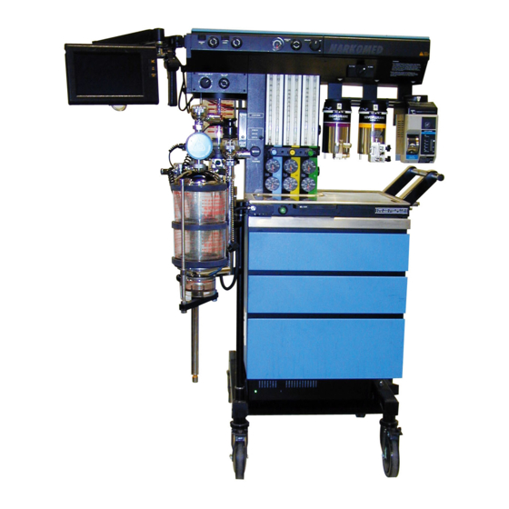
- Page 6 RETURN TO THIS MANUAL'S TABLE OF CONTENTS RETURN TO CD-ROM TABLE OF CONTENTS NARKOMED 2C ANESTHESIA SYSTEM VENTILATOR DISPLAY O.R. DATA MANAGER (OPTIONAL) REMOTE DISPLAY DATAGRIP BREATHING SYSTEM SENSOR INTERFACE PANEL SV50533 Rev. D...
-
Page 7: Introduction
The PMS PROCEDURE in Section 6 must also be performed after any component has been replaced. The general arrangement of the Narkomed 2C Anesthesia System is shown on the opposite page. WARNINGS are used in this manual before procedures which if not performed correctly could result in personal injury. - Page 8 RETURN TO THIS MANUAL'S TABLE OF CONTENTS RETURN TO CD-ROM TABLE OF CONTENTS INTRODUCTION NM2C Copyright Copyright © 1999 by Draeger Medical, Inc. All rights reserved. No part of this publication may be reproduced, transmitted, transcribed, or stored in a retrieval system in any form or by any means, electronic or mechanical, including photocopying and recording, without the written permission of Draeger Medical, Inc.
-
Page 9: Diagnostics
DIAGNOSTICS 2.0 DIAGNOSTICS The Narkomed 2C contains a diagnostic system that monitors certain system functions and records their operational status. A series of tests is performed when the system is powered up and the results are displayed on the diagnostics screen shown in Figure 2-1. The display... -
Page 10: Service Log
RETURN TO THIS MANUAL'S TABLE OF CONTENTS RETURN TO CD-ROM TABLE OF CONTENTS DIAGNOSTICS (continued) NM2C Main Service Screen 2.1.1 View Mode The Main Service Screen displays the machine serial number, the last service date, hours run since last service and total hours run. Selections listed on the right side of the display allow entry into additional service screens. - Page 11 RETURN TO THIS MANUAL'S TABLE OF CONTENTS RETURN TO CD-ROM TABLE OF CONTENTS NM2C DIAGNOSTICS (continued) 2.1.2 Service Mode The following additional service mode screens are available by selecting the appropriate Service Code: PMS: For performing scheduled Periodic Manufacturer’s Service INST: For initial installation of the NM2C.
- Page 12 RETURN TO THIS MANUAL'S TABLE OF CONTENTS RETURN TO CD-ROM TABLE OF CONTENTS DIAGNOSTICS (continued) NM2C Service Log The Service Log Screen displays a tabular listing of each service event including date, time, parameter, code and event description as shown in Figure 2-4.
-
Page 13: Pms Criteria Screen
RETURN TO THIS MANUAL'S TABLE OF CONTENTS RETURN TO CD-ROM TABLE OF CONTENTS NM2C DIAGNOSTICS (continued) PMS Criteria Screen The PMS Criteria Screen allows a service representative to select for display the month of the next scheduled Periodic Manufacturer’s Service. This screen is shown in Figure 2-5. -
Page 14: Oxygen Monitor Service Screen
RETURN TO THIS MANUAL'S TABLE OF CONTENTS RETURN TO CD-ROM TABLE OF CONTENTS DIAGNOSTICS (continued) NM2C Oxygen Monitor Service Screen The Oxygen Monitor Service Screen shown in Figure 2-6 displays current readings for the O cells, a zero calibration procedure, and the stored calibration values. -
Page 15: Pressure Monitor Service Screen
RETURN TO THIS MANUAL'S TABLE OF CONTENTS RETURN TO CD-ROM TABLE OF CONTENTS NM2C DIAGNOSTICS (continued) Pressure Monitor Service Screen The Pressure Monitor Service Screen shown in Figure 2-7 displays the current reading for airway pressure, a procedure for zero and span calibration, and the stored calibration values. -
Page 16: Nvram Dump Screen
RETURN TO THIS MANUAL'S TABLE OF CONTENTS RETURN TO CD-ROM TABLE OF CONTENTS DIAGNOSTICS (continued) NM2C NVRAM Dump Screen The NVRAM Dump Screen displays locations of non-volatile memory (processor status registers). This screen is shown in Figure 2-8. To enter this screen from the Main Service Screen, highlight NVRAM DUMP (ref. -
Page 17: Troubleshooting
Power Supply and Voltage Distribution In the NARKOMED 2C, +5VDC, +12VDC and -12VDC are supplied to J15 on the processor board; +8VDC is supplied to J4 on the alarm channel and is also distributed to the ventilator controller via J3 on the alarm channel. These voltages can be measured at the connectors shown in Figure 3-1. - Page 18 TROUBLESHOOTING GUIDE (continued) NM2C VENTILATOR SPEAKER CONTROLLER VAPORIZER SELECT O2 SENSOR PROCESSOR FLOWMETER ORDM RESP VOL LIGHTS SENSOR ALARM CHANNEL 30 PSI DATAGRIP REMOTE DISPLAY FILTER CONVENIENCE RECEPTACLES BATTERY FILTER POWER SUPPLY MAINS Figure 3-2: NARKOMED 2C BLOCK DIAGRAM (ELECTRICAL)
-
Page 19: Battery
Troubleshooting Guides Table 3-2 lists common failure modes and symptoms (excluding simultaneous multiple faults) for the monitoring and display devices in the NARKOMED 2C. Each failure mode or symptom is keyed to a troubleshooting guide flow chart at the back of this section to assist the TSR in locating a problem. These flow charts assume that the machine is plugged into an AC outlet with the correct voltage, and the machine is not running on its backup battery. - Page 20 RETURN TO THIS MANUAL'S TABLE OF CONTENTS RETURN TO CD-ROM TABLE OF CONTENTS TROUBLESHOOTING GUIDE (continued) NM2C GUIDE 1: Loss of O Monitor START IS O2 MONITOR WORKING PROPERLY? CONNECT SENSOR CORD TO INTERFACE PANEL SENSOR CORD CONNECTED TO INTERFACE PANEL? INSTALL SENSOR ELEMENT CORRECTLY...
- Page 21 RETURN TO THIS MANUAL'S TABLE OF CONTENTS RETURN TO CD-ROM TABLE OF CONTENTS NM2C TROUBLESHOOTING GUIDE (continued) GUIDE 2: Loss of Breathing Pressure Monitor START BREATHING PRESSURE MONITOR WORKING PROPERLY? CHECK PILOT LINE CONNECTION AT BOTH ENDS PILOT LINE CONNECTED? CHECK INTERNAL TUBING FROM INTERFACE PANEL...
- Page 22 RETURN TO THIS MANUAL'S TABLE OF CONTENTS RETURN TO CD-ROM TABLE OF CONTENTS TROUBLESHOOTING GUIDE (continued) NM2C GUIDE 3: Loss of Respiratory Volume Monitor START IS RESPIRATORY VOLUME MONITOR WORKING PROPERLY? CONNECT SENSOR CORD TO INTERFACE PANEL IS SENSOR CORD CONNECTED TO INTERFACE PANEL? CHECK SENSOR AND VALVE...
- Page 23 RETURN TO THIS MANUAL'S TABLE OF CONTENTS RETURN TO CD-ROM TABLE OF CONTENTS NM2C TROUBLESHOOTING GUIDE (continued) GUIDE 4: No Audio Alarms START AUDIO ALARMS WORKING? CHECK SPEAKER WIRE HARNESS AND CONNECTION TO PROCESSOR BOARD J2 AUDIO ALARMS WORKING? SUBSTITUTE ANOTHER SPEAKER REPLACE AUDIO ALARMS...
- Page 24 RETURN TO THIS MANUAL'S TABLE OF CONTENTS RETURN TO CD-ROM TABLE OF CONTENTS TROUBLESHOOTING GUIDE (continued) NM2C GUIDE 5: Serial Port Communication Failure START SERIAL PORT COMMUNICATION FAILURE? CHECK PERIPHERAL AND HOST SERIAL PORT CONFIGURATION SETTINGS SERIAL PORT COMMUNICATION FAILURE? CONNECT PERIPHERAL CABLE TO SERIAL INTERFACE...
- Page 25 RETURN TO THIS MANUAL'S TABLE OF CONTENTS RETURN TO CD-ROM TABLE OF CONTENTS NM2C TROUBLESHOOTING GUIDE (continued) GUIDE 6: No O Supply Pressure Alarms START O2 SUPPLY PRESSURE ALARMS FUNCTIONAL? CHECK O2 LOW PRESSURE ALARM SWITCH LOW O2 AND WIRE HARNESS, SUPPLY PRESSURE ON ALL CONNECTIONS TO DISPLAY ONLY?
- Page 26 RETURN TO THIS MANUAL'S TABLE OF CONTENTS RETURN TO CD-ROM TABLE OF CONTENTS TROUBLESHOOTING GUIDE (continued) NM2C GUIDE 7: Display Blank Upon System Power-up START IS DISPLAY BLANK UPON SYSTEM POWER-UP? POWER OFF, CONNECT DISPLAY CABLE TO PROCESSOR PORT J4 IS DISPLAY CABLE CONNECTED TO PROCESSOR...
- Page 27 RETURN TO THIS MANUAL'S TABLE OF CONTENTS RETURN TO CD-ROM TABLE OF CONTENTS NM2C TROUBLESHOOTING GUIDE (continued) GUIDE 8: Display Keypanel Inoperative START DOES DISPLAY KEYPANEL OPERATE PROPERLY? POWER OFF, SUBSTITUTE ANOTHER DISPLAY POWER OFF, DOES REPLACE DISPLAY PERFORM A DISPLAY KEYPANEL ASSEMBLY COMPLETE PMS...
- Page 28 RETURN TO THIS MANUAL'S TABLE OF CONTENTS RETURN TO CD-ROM TABLE OF CONTENTS TROUBLESHOOTING GUIDE (continued) NM2C GUIDE 9: No Datagrip Response START DATAGRIP WORKING PROPERLY? CONNECT DATAGRIP CABLE TO PROCESSOR PORT J3 DATAGRIP CABLE CONNECTED? CHECK POWER SUPPLY VOLTAGES, REPLACE POWER SUPPLY IF OUT OF TOLERANCE...
- Page 29 RETURN TO THIS MANUAL'S TABLE OF CONTENTS RETURN TO CD-ROM TABLE OF CONTENTS NM2C TROUBLESHOOTING GUIDE (continued) GUIDE 10: Ventilator Inoperative START IS VENTILATOR WORKING PROPERLY? CHECK CABLES AND TUBING CONNECTIONS AT VENTILATOR VERIFY CORRECT SETTINGS: CONTROLLER, REPLACE VENTILATOR SWITCH ON, CONTROLLER ASSEMBLY AS INSP.
- Page 30 RETURN TO THIS MANUAL'S TABLE OF CONTENTS RETURN TO CD-ROM TABLE OF CONTENTS...
-
Page 31: Replacement Procedures
REPLACEMENT PROCEDURES REPLACEMENT PROCEDURES This section outlines removal and replacement procedures for the field-replaceable assemblies of the NARKOMED 2C Anesthesia System. These procedures are to be performed only by a Draeger Medical, Inc. qualified Technical Service Representative (TSR). The following are the only procedures authorized by Draeger Medical, Inc. to be performed in the field. -
Page 32: Cylinder Yoke Assemblies
RETURN TO THIS MANUAL'S TABLE OF CONTENTS RETURN TO CD-ROM TABLE OF CONTENTS REPLACEMENT PROCEDURES (continued) NM2C Cylinder Yoke Assemblies Each cylinder yoke contains a replaceable filter and check valve assembly. Replacement of this assembly requires that the yoke be removed from the anesthesia machine. - Page 33 RETURN TO THIS MANUAL'S TABLE OF CONTENTS RETURN TO CD-ROM TABLE OF CONTENTS NM2C REPLACEMENT PROCEDURES (continued) YOKE ASSEMBLY (TYPICAL) YOKE SPACER FILTER AND CHECK VALVE ASSEMBLY LINE Figure 4-1: CYLINDER YOKE ASSEMBLY Rev. G...
- Page 34 RETURN TO THIS MANUAL'S TABLE OF CONTENTS RETURN TO CD-ROM TABLE OF CONTENTS REPLACEMENT PROCEDURES (continued) NM2C 4.1.12 Position the yoke on the spacer, and install the two mounting screws and lockwashers. Tighten the screws securely. Connect the gas line fitting to the yoke.
- Page 35 RETURN TO THIS MANUAL'S TABLE OF CONTENTS RETURN TO CD-ROM TABLE OF CONTENTS NM2C REPLACEMENT PROCEDURES (continued) Cylinder Pressure Regulators Access to the cylinder pressure regulators requires that the table top be removed from the anesthesia machine. Figure 4-2 shows the mounting arrangement of the regulators and typical connections.
-
Page 36: Cylinder Pressure Regulators
RETURN TO THIS MANUAL'S TABLE OF CONTENTS RETURN TO CD-ROM TABLE OF CONTENTS REPLACEMENT PROCEDURES (continued) NM2C TOP VIEW OF NARKOMED 4 WITH TABLE TOP REMOVED O CYLINDER N O CYLINDER PRESSURE PRESSURE REGULATOR REGULATOR SCREWS AIR OR OPTIONAL 3RD GAS CYLINDER PRESSURE REGULATOR TEST GAUGE CONNECTION... - Page 37 RETURN TO THIS MANUAL'S TABLE OF CONTENTS RETURN TO CD-ROM TABLE OF CONTENTS NM2C REPLACEMENT PROCEDURES (continued) 4.2.14 Tighten the regulator mounting setscrews to a torque of 50 to 55 in. lbs. 4.2.15 Tighten the compression fittings. 4.2.16 Locate the TEE fitting in the ¼ in. diameter regulator output line, and remove the plug from the TEE fitting.
- Page 38 RETURN TO THIS MANUAL'S TABLE OF CONTENTS RETURN TO CD-ROM TABLE OF CONTENTS REPLACEMENT PROCEDURES (continued) NM2C This page intentionally left blank Rev. A...
-
Page 39: Cylinder Cutoff Valves (Canada)
RETURN TO THIS MANUAL'S TABLE OF CONTENTS RETURN TO CD-ROM TABLE OF CONTENTS NM2C REPLACEMENT PROCEDURES (continued) Cylinder Cutoff Valves (Canada) Access to the cylinder cutoff valves requires removal of the table top from the anesthesia machine. Figure 4-3 shows the locations of the O , Air or 3rd gas, and N O cutoff valve assemblies. - Page 40 RETURN TO THIS MANUAL'S TABLE OF CONTENTS RETURN TO CD-ROM TABLE OF CONTENTS REPLACEMENT PROCEDURES (continued) NM2C SV50526 O2 CYLINDER AIR OR 3RD GAS N2O CYLINDER CUTOFF VALVE CYLINDER CUTOFF VALVE ASSEMBLY CUTOFF VALVE ASSEMBLY ASSEMBLY Figure 4-3: CYLINDER CUTOFF VALVES (CANADA) Rev.
- Page 41 RETURN TO THIS MANUAL'S TABLE OF CONTENTS RETURN TO CD-ROM TABLE OF CONTENTS NM2C REPLACEMENT PROCEDURES (continued) 4.3.13 Connect and tighten the compression fittings at points marked C on the illustration. 4.3.14 Perform the following test: --Remove the plug from the test gauge connection at the Tee fitting in the regulator outlet piping, and install a test gauge.
- Page 42 RETURN TO THIS MANUAL'S TABLE OF CONTENTS RETURN TO CD-ROM TABLE OF CONTENTS REPLACEMENT PROCEDURES (continued) NM2C Cylinder and Pipeline Pressure Gauges Replacement of the cylinder and pipeline pressure gauges requires that the plexiglass front cover be removed from the gas instrumentation panel, and also the rear cover for access to the gauge connections.
-
Page 43: Cylinder And Pipeline Pressure Gauges
RETURN TO THIS MANUAL'S TABLE OF CONTENTS RETURN TO CD-ROM TABLE OF CONTENTS NM2C REPLACEMENT PROCEDURES (continued) REAR VIEW OF FLOWMETER HOUSING WITH REAR COVER REMOVED GAUGE MOUNTING NUTS (TYPICAL) FLEXIBLE TUBING CONNECTION (PIPELINE PRESSURE GAUGES) COMPRESSION FITTING SV50501 (CYLINDER PRESSURE GAUGES) Figure 4-4: CYLINDER AND PIPELINE PRESSURE GAUGES Rev. - Page 44 RETURN TO THIS MANUAL'S TABLE OF CONTENTS RETURN TO CD-ROM TABLE OF CONTENTS REPLACEMENT PROCEDURES (continued) NM2C NOTE: Intermediate assemblies may need to be removed to allow access to the gauge connections and mounting hardware. Be sure to keep a record of the disassembly sequence so that all tubing can be correctly re-assembled.
- Page 45 RETURN TO THIS MANUAL'S TABLE OF CONTENTS RETURN TO CD-ROM TABLE OF CONTENTS NM2C REPLACEMENT PROCEDURES (continued) 4.4.14.1 Open the cylinder valve and check for a pressure indication on the corresponding gauge at the gas instrumentation panel. NOTE: The cylinder used for this test must contain the following minimum pressure: : 1000 Psi : 700 Psi...
-
Page 46: Flowmeters
RETURN TO THIS MANUAL'S TABLE OF CONTENTS RETURN TO CD-ROM TABLE OF CONTENTS REPLACEMENT PROCEDURES (continued) NM2C Flowmeters The flowmeter tubes are held by compression in gaskets at the top and bottom of each tube. Each upper gasket is seated in an adjustable retainer that allows removal of the tube as shown in Figure 4-5. - Page 47 RETURN TO THIS MANUAL'S TABLE OF CONTENTS RETURN TO CD-ROM TABLE OF CONTENTS NM2C REPLACEMENT PROCEDURES (continued) FLOW TUBE RETAINER SCREW UPPER FLOW TUBE RETAINER FLOW TUBE LIGHTING CHANNEL FLOW RESTRICTOR SV40605 GUIDE RING GASKET Figure 4-5: FLOWMETERS Rev. G 4-17...
- Page 48 RETURN TO THIS MANUAL'S TABLE OF CONTENTS RETURN TO CD-ROM TABLE OF CONTENTS REPLACEMENT PROCEDURES (continued) NM2C 4.5.12 Loosen the screw directly above the flowmeter tube to be replaced. Turning the screw counter clockwise will raise the upper flow tube retainer.
- Page 49 RETURN TO THIS MANUAL'S TABLE OF CONTENTS RETURN TO CD-ROM TABLE OF CONTENTS NM2C REPLACEMENT PROCEDURES (continued) 4.5.19 Place the plexiglass cover over the gauges and flow tubes, and ensure that the cover is fitted properly over the flow control valves. 4.5.20 Place the knob guard over the flow control valves and install its two retaining screws.
- Page 50 RETURN TO THIS MANUAL'S TABLE OF CONTENTS RETURN TO CD-ROM TABLE OF CONTENTS REPLACEMENT PROCEDURES (continued) NM2C Flow Control Valves The flow control valves have replaceable elements that are removable from the front of the gas instrumentation panel as shown in Figure 4-6. Each flow control knob has a clockwise positive stop arrangement that prevents damage to the valve seat.
-
Page 51: Flow Control Valves
RETURN TO THIS MANUAL'S TABLE OF CONTENTS RETURN TO CD-ROM TABLE OF CONTENTS NM2C REPLACEMENT PROCEDURES (continued) VALVE FLOW CONTROL HOUSING VALVE STOP PIN WRENCH FLATS KNOB GUARD LABEL KNOB SV50502 Figure 4-6: FLOW CONTROL VALVES Rev. G 4-21... - Page 52 RETURN TO THIS MANUAL'S TABLE OF CONTENTS RETURN TO CD-ROM TABLE OF CONTENTS REPLACEMENT PROCEDURES (continued) NM2C 4.6.14 Set the System Power switch to ON. 4.6.15A For the O flow control valve: Open the oxygen cylinder valve. Turn the flow control valve clockwise until the flow rate will not drop any further.
-
Page 53: Oxygen Supply Pressure Failure Protection Device
RETURN TO THIS MANUAL'S TABLE OF CONTENTS RETURN TO CD-ROM TABLE OF CONTENTS NM2C REPLACEMENT PROCEDURES (continued) Oxygen Supply Pressure Failure Protection Device The oxygen supply failure protection devices (failsafe assemblies) are located within the flowmeter housing. Access to these assemblies requires removal of the rear cover. - Page 54 RETURN TO THIS MANUAL'S TABLE OF CONTENTS RETURN TO CD-ROM TABLE OF CONTENTS REPLACEMENT PROCEDURES (continued) NM2C OXYGEN SUPPLY FAILURE PROTECTION DEVICE (N2O CONTROL DEVICE ILLUSTRATED) O2 CONTROL LINE TO N2O FLOW CONTROL VALVE CHECK VALVE FROM CYLINDER PRESSURE REGULATOR FROM PIPELINE INLET ASSEMBLY SV50536...
- Page 55 RETURN TO THIS MANUAL'S TABLE OF CONTENTS RETURN TO CD-ROM TABLE OF CONTENTS NM2C REPLACEMENT PROCEDURES (continued) 4.7.12 Perform the following test: 4.7.12.1 Open the cylinder valves. 4.7.12.2 Set the System Power switch to ON. 4.7.12.3 Set the oxygen flow to five liters per minute. 4.7.12.4 Set the other gas flow to five liters per minute.
- Page 56 RETURN TO THIS MANUAL'S TABLE OF CONTENTS RETURN TO CD-ROM TABLE OF CONTENTS REPLACEMENT PROCEDURES (continued) NM2C Alarm Channel and Oxygen Supply Pressure Alarm Switch The alarm channel assembly includes the oxygen supply pressure alarm switch, the alarm circuit board, and the system power switch. Whenever the alarm channel is replaced, the oxygen supply pressure alarm switch must be tested to ensure that its operating point is set correctly.
-
Page 57: Alarm Channel And Oxygen Supply Pressure Alarm Switch
RETURN TO THIS MANUAL'S TABLE OF CONTENTS RETURN TO CD-ROM TABLE OF CONTENTS NM2C REPLACEMENT PROCEDURES (continued) REAR VIEW SIDE VIEW UPPER ALARM CHANNEL MOUNTING SCREW ALARM CIRCUIT BOARD AUXILARY O2 FLOWMETER CONNECTION O2 CONNECTIONS ADJUSTMENT WHEEL INCREASE SETPOINT OXYGEN DECREASE SETPOINT SUPPLY PRESSURE... - Page 58 RETURN TO THIS MANUAL'S TABLE OF CONTENTS RETURN TO CD-ROM TABLE OF CONTENTS REPLACEMENT PROCEDURES (continued) NM2C 4.8.15 From the back of the flowmeter housing, remove the upper and lower alarm channel mounting screws. 4.8.16 At the front of the machine, pull the alarm channel assembly forward, and feed the flowmeter lights wire harness through the hole at the top of the alarm channel.
- Page 59 RETURN TO THIS MANUAL'S TABLE OF CONTENTS RETURN TO CD-ROM TABLE OF CONTENTS NM2C REPLACEMENT PROCEDURES (continued) 4.8.32 Open an oxygen cylinder valve and turn the System Power switch to 4.8.33 Set the oxygen flow to five liters per minute. 4.8.34 Close the oxygen cylinder valve.
- Page 60 RETURN TO THIS MANUAL'S TABLE OF CONTENTS RETURN TO CD-ROM TABLE OF CONTENTS REPLACEMENT PROCEDURES (continued) NM2C Oxygen Ratio Controller The Oxygen Ratio Controller (ORC) is part of the N O flowmeter sub-assembly and is located within the flowmeter housing. The ORC is accessible by removing the rear flowmeter housing cover.
-
Page 61: Oxygen Ratio Controller
RETURN TO THIS MANUAL'S TABLE OF CONTENTS RETURN TO CD-ROM TABLE OF CONTENTS NM2C REPLACEMENT PROCEDURES (continued) REAR VIEW OF FLOWMETER HOUSING SV50504 WITH REAR COVER REMOVED ADJUSTING SCREW LOCKNUT CONNECTION ASSEMBLY O-RING, #105 (NEOPRENE) FILTER O-RING, 0.066 X 0.042 (BUNA-N) ASSEMBLY MOUNTING... - Page 62 RETURN TO THIS MANUAL'S TABLE OF CONTENTS RETURN TO CD-ROM TABLE OF CONTENTS REPLACEMENT PROCEDURES (continued) NM2C 4.9.12 Perform the ORC adjustment procedure given in Section 5 of this manual. NOTE: There are two adjustment procedures - one for ORC P/N 411800, and one for low flow ORC P/N 4113229.
-
Page 63: Vaporizers
RETURN TO THIS MANUAL'S TABLE OF CONTENTS RETURN TO CD-ROM TABLE OF CONTENTS NM2C REPLACEMENT PROCEDURES (continued) 4.10 Vaporizers Each vaporizer is held to the machine by two metric sized hex screws. These screws are accessible at the back of the vaporizer mount, below the interlock mechanism as shown in Figure 4-10. - Page 64 RETURN TO THIS MANUAL'S TABLE OF CONTENTS RETURN TO CD-ROM TABLE OF CONTENTS REPLACEMENT PROCEDURES (continued) NM2C VAPORIZER MOUNT LOCKING INTERLOCK HANDWHEEL SETSCREW VAPORIZER VAPORIZER MOUNTING SCREWS (2 EA) (RECESSED) SV20325 VAPORIZER INTERLOCK MECHANISM REAR VIEW LEFT SETSCREW CENTER VAPORIZER SETSCREWS RIGHT MOUNTING SCREW...
- Page 65 RETURN TO THIS MANUAL'S TABLE OF CONTENTS RETURN TO CD-ROM TABLE OF CONTENTS NM2C REPLACEMENT PROCEDURES (continued) NOTE: Should a vaporizer containing anesthetic agent be accidentally tilted more than 45 degrees, it must be drained and flushed in accordance with instructions given in the manual supplied with the vaporizer.
- Page 66 RETURN TO THIS MANUAL'S TABLE OF CONTENTS RETURN TO CD-ROM TABLE OF CONTENTS REPLACEMENT PROCEDURES (continued) NM2C 4.11 Flush Valve The O flush valve is located at the front of the machine next to the fresh gas outlet. Access to the flush valve requires removal of the table top. Figure 4-11 shows the mounting and assembly details of the flush valve.
-
Page 67: Flush Valve
RETURN TO THIS MANUAL'S TABLE OF CONTENTS RETURN TO CD-ROM TABLE OF CONTENTS NM2C REPLACEMENT PROCEDURES (continued) COMPRESSION FITTINGS RESTRICTOR FLUSH VALVE SPACER ACCESS HOLES WASHER INTERNAL TOOTH LOCKWASHER PUSH BUTTON GUARD RING FRONT VIEW WITH TABLE TOP REMOVED SET SCREWS SV49099 Figure 4-11: O FLUSH VALVE... - Page 68 RETURN TO THIS MANUAL'S TABLE OF CONTENTS RETURN TO CD-ROM TABLE OF CONTENTS REPLACEMENT PROCEDURES (continued) NM2C 4.11.14 Hold the O Flush button in and turn it until a set screw is visible through an access hole in the guard ring. Tighten the set screw. Rotate the button 180 degrees until the other set screw is visible, and tighten the set screw.
-
Page 69: And Av2+ Ventilator Controller Assembly
RETURN TO THIS MANUAL'S TABLE OF CONTENTS RETURN TO CD-ROM TABLE OF CONTENTS NM2C REPLACEMENT PROCEDURES (continued) 4.12 AV-2 and AV-2+ Ventilator Controller Assembly The Ventilator Controller assembly is attached to the left front panel of the ventilator box and includes electrical and pneumatic components. Figures 4-12 and 4-12A show the mounting screw locations and connections to the ventilator controller. - Page 70 RETURN TO THIS MANUAL'S TABLE OF CONTENTS RETURN TO CD-ROM TABLE OF CONTENTS REPLACEMENT PROCEDURES (continued) NM2C TO VENTURI TO AUTO- RANGING VALVE TO VENT O2 SUPPLY TOP VIEW OF CONTROLLER ASSEMBLY IN VENTILATOR RETAINING SCREWS (2X) SUPPLY VALVE INSPIRATORY SOLENOID FLOW REGULATOR...
- Page 71 RETURN TO THIS MANUAL'S TABLE OF CONTENTS RETURN TO CD-ROM TABLE OF CONTENTS NM2C REPLACEMENT PROCEDURES (continued) SELECTOR CABLE SV49050 FROM INTERFACE PANEL J2 (ALARM CHANNEL WIRE HARNESS) AV2+ CONTROLLER & (SELECTOR CABLE) BEZEL ASSEMBLY Figure 4-12A: AV2+ VENTILATOR CONTROLLER ASSEMBLY Rev.
- Page 72 RETURN TO THIS MANUAL'S TABLE OF CONTENTS RETURN TO CD-ROM TABLE OF CONTENTS REPLACEMENT PROCEDURES (continued) NM2C This page intentionally left blank Rev. F 4-40B...
- Page 73 RETURN TO THIS MANUAL'S TABLE OF CONTENTS RETURN TO CD-ROM TABLE OF CONTENTS NM2C REPLACEMENT PROCEDURES (continued) 4.12.10 Slide the controller into the ventilator box, carefully fit the locking tab into its receptacle at the right side of the panel, and slide the assembly to the right until it is properly seated.
- Page 74 RETURN TO THIS MANUAL'S TABLE OF CONTENTS RETURN TO CD-ROM TABLE OF CONTENTS REPLACEMENT PROCEDURES (continued) NM2C 4.13 Convenience Outlet AC Power Filter The convenience outlet AC power filter is located at the back of the ventilator box near the AC convenience outlets. Access to the power filter requires removal of the ventilator box top panel.
-
Page 75: Convenience Outlet Ac Power Filter
RETURN TO THIS MANUAL'S TABLE OF CONTENTS RETURN TO CD-ROM TABLE OF CONTENTS NM2C REPLACEMENT PROCEDURES (continued) NARKOMED 2C VENTILATOR BOX TOP VIEW FILTER MOUNTING SPACERS (2X) BROWN GREEN/ BLACK YELLOW BLUE WHITE CONVENIENCE OUTLET AC POWER FILTER COVER SCREWS... - Page 76 RETURN TO THIS MANUAL'S TABLE OF CONTENTS RETURN TO CD-ROM TABLE OF CONTENTS REPLACEMENT PROCEDURES (continued) NM2C 4.14 Ventilator Bellows Valve and Guide Assembly with Pressure Limit Control The Ventilator Bellows Valve and Guide Assembly, and the Pressure Limit Control are located in the bellows box on the left side of the machine. Access to the components requires removal of the bellows box front panel, and removal of the upper bellows support plate from the bellows box.
- Page 77 RETURN TO THIS MANUAL'S TABLE OF CONTENTS RETURN TO CD-ROM TABLE OF CONTENTS NM2C REPLACEMENT PROCEDURES (continued) SV50514 1:2 .5 I:E RATIO FREQUENCY /min BELLOWS BOX FRONT VIEW FRONT PANEL BELLOWS MOUNTING SCREWS (4X) GUIDE FRONT PANEL AND KNOB ASSEMBLY CANISTER VOLUME INDICATOR SET SCREWS (2X)
- Page 78 RETURN TO THIS MANUAL'S TABLE OF CONTENTS RETURN TO CD-ROM TABLE OF CONTENTS REPLACEMENT PROCEDURES (continued) NM2C SV50414 BELLOWS BOX FRONT VIEW WITH FRONT PANEL REMOVED FLEX TUBING FROM CONTROLLER UPPER BELLOWS SUPPORT PLATE SUPPORT PLATE BOTTOM VIEW SCREWS (3X) OF BELLOWS BOX PRESSURE LIMIT CONTROL...
- Page 79 RETURN TO THIS MANUAL'S TABLE OF CONTENTS RETURN TO CD-ROM TABLE OF CONTENTS NM2C REPLACEMENT PROCEDURES (continued) NOTE: If components are removed from the support plate, be sure that any spacers and O-rings are correctly positioned during reinstallation. 4.14.14 Following component replacement, position the support plate in the bellows box and reconnect the large and small diameter tubing that was previously removed.
-
Page 80: Caster
RETURN TO THIS MANUAL'S TABLE OF CONTENTS RETURN TO CD-ROM TABLE OF CONTENTS REPLACEMENT PROCEDURES (continued) NM2C 4.15 Caster Each caster is retained by a set screw in the side of the lower frame rail as shown in Figure 4-15. Caster replacement requires that the machine be tilted to provide enough clearance for the caster stem to be withdrawn from the bottom of the frame rail. - Page 81 RETURN TO THIS MANUAL'S TABLE OF CONTENTS RETURN TO CD-ROM TABLE OF CONTENTS NM2C REPLACEMENT PROCEDURES (continued) 2 TO 3 INCHES SETSCREW PLASTIC Figure 4-15: CASTER REPLACEMENT 4-49...
- Page 82 RETURN TO THIS MANUAL'S TABLE OF CONTENTS RETURN TO CD-ROM TABLE OF CONTENTS REPLACEMENT PROCEDURES (continued) NM2C 4.16 Battery The backup battery is located in the power supply compartment below the cabinet drawers. Access to the power supply requires removal of the lower drawers and removal of the power supply compartment cover.
-
Page 83: Battery
RETURN TO THIS MANUAL'S TABLE OF CONTENTS RETURN TO CD-ROM TABLE OF CONTENTS NM2C REPLACEMENT PROCEDURES (continued) RETAINER BAR TOP VIEW OF POWER SUPPLY SCREW WITH COVER REMOVED RETAINER BATTERY BATTERY WIRE HARNESS BLACK SV50507 YELLOW Figure 4-16: BATTERY REPLACEMENT 4-51... - Page 84 RETURN TO THIS MANUAL'S TABLE OF CONTENTS RETURN TO CD-ROM TABLE OF CONTENTS REPLACEMENT PROCEDURES (continued) NM2C 4.16.12 Reinstall the power supply compartment cover with the four screws that were previously removed. 4.16.13 Reinstall the bottom and center cabinet drawers. Ensure that the locking tabs are correctly in place.
- Page 85 RETURN TO THIS MANUAL'S TABLE OF CONTENTS RETURN TO CD-ROM TABLE OF CONTENTS NM2C REPLACEMENT PROCEDURES (continued) 4.17 Power Supply The primary power supply is located in the power supply and battery compartment below the cabinet drawers. Access to the power supply requires removal of the lower drawers and removal of the power supply compartment cover.
-
Page 86: Power Supply
RETURN TO THIS MANUAL'S TABLE OF CONTENTS RETURN TO CD-ROM TABLE OF CONTENTS REPLACEMENT PROCEDURES (continued) NM2C TB1 (BATTERY WIRE HARNESS) CIRCUIT BREAKER WIRE HARNESS J2 (LAMP CONNECTOR) WHT/BLU WHT/BRN GRN/YEL CAPTIVE MOUNTING SCREWS (4X) POWER SUPPLY ASSEMBLY POWER SUPPLY COMPARTMENT SV50506 Figure 4-17: POWER SUPPLY... - Page 87 RETURN TO THIS MANUAL'S TABLE OF CONTENTS RETURN TO CD-ROM TABLE OF CONTENTS NM2C REPLACEMENT PROCEDURES (continued) 4.17.10 Disconnect the battery wire harness from the center circuit breaker (CB2). Note the wire color and position of the wires so that the harness can be reinstalled in the same manner.
- Page 88 RETURN TO THIS MANUAL'S TABLE OF CONTENTS RETURN TO CD-ROM TABLE OF CONTENTS REPLACEMENT PROCEDURES (continued) NM2C 4.17.20 Join the lamp connector to J2 on the bottom board of the power supply. Power Indicator Lamp Wire Connections to J2: TERMINAL WIRE COLOR Black 4.17.21 Reinstall the power supply compartment to the frame rails with the...
- Page 89 RETURN TO THIS MANUAL'S TABLE OF CONTENTS RETURN TO CD-ROM TABLE OF CONTENTS NM2C REPLACEMENT PROCEDURES (continued) This page intentionally left blank Rev. A 4-55B...
- Page 90 RETURN TO THIS MANUAL'S TABLE OF CONTENTS RETURN TO CD-ROM TABLE OF CONTENTS REPLACEMENT PROCEDURES (continued) NM2C 4.18 Processor Assembly The Processor Assembly is located in the ventilator chassis and is accessible by removing the back panel of the ventilator box. Figure 4-18 shows the electrical and pneumatic connections to the processor assembly, and its mounting arrangement.
-
Page 91: Processor Assembly
RETURN TO THIS MANUAL'S TABLE OF CONTENTS RETURN TO CD-ROM TABLE OF CONTENTS NM2C REPLACEMENT PROCEDURES (continued) VENTILATOR BOX TOP VIEW SV50537 WITH COVER REMOVED BREATHING PRESSURE SENSOR CONNECTION J1 (O2 SENSOR) (VAPOR BOX) (ALARM) (SPEAKER) (ORDM) J15 (POWER) J22 (FAN) (VOLUME SENSOR) REAR PANEL MOUNTING SCREWS (6X) - Page 92 RETURN TO THIS MANUAL'S TABLE OF CONTENTS RETURN TO CD-ROM TABLE OF CONTENTS REPLACEMENT PROCEDURES (continued) NM2C 4.18.9 Slide the processor assembly into the ventilator chassis and secure it with the two screws that were previously removed. 4.18.10 Connect the O.R. DATA MANAGER ribbon cable to J5 on the processor board.
-
Page 93: Remote Display Assembly
RETURN TO THIS MANUAL'S TABLE OF CONTENTS RETURN TO CD-ROM TABLE OF CONTENTS NM2C REPLACEMENT PROCEDURES (continued) 4.19 Remote Display Assembly The Remote Display Assembly is mounted on a rod extending from the Datagrip assembly located at the outboard end of the display arm. Figure 4-19 illustrates the Display assembly mounting arrangement. - Page 94 RETURN TO THIS MANUAL'S TABLE OF CONTENTS RETURN TO CD-ROM TABLE OF CONTENTS REPLACEMENT PROCEDURES (continued) NM2C REMOTE DATAGRIP DISPLAY PORT PORT REAR VIEW OF NARKOMED 2C CABLE CLAMPS ACCESS TO CABLE CLAMPS CLAMP (APPROXIMATE SCREWS LOCATION) DISPLAY ASSEMBLY MOUNTING...
- Page 95 RETURN TO THIS MANUAL'S TABLE OF CONTENTS RETURN TO CD-ROM TABLE OF CONTENTS NM2C REPLACEMENT PROCEDURES (continued) 4.20 DATAGRIP Assembly The Datagrip Assembly is attached to the outboard end of the display arm and comprises the handle and trigger switch, thumbwheel encoder, cable, and mounting rod for the display.
-
Page 96: Datagrip Assembly
RETURN TO THIS MANUAL'S TABLE OF CONTENTS RETURN TO CD-ROM TABLE OF CONTENTS REPLACEMENT PROCEDURES (continued) NM2C DATAGRIP REMOTE PORT DISPLAY REAR VIEW OF PORT NARKOMED 2C CABLE CLAMPS MOUNTING SCREW SPACER LOCKWASHER BEARING SPACER CABLE CLAMPS (APPROXIMATE LOCATION) DELRIN SPACER... - Page 97 RETURN TO THIS MANUAL'S TABLE OF CONTENTS RETURN TO CD-ROM TABLE OF CONTENTS NM2C REPLACEMENT PROCEDURES (continued) 4.20.11 Slide the display onto the mounting rod, oriented so that the mounting clamps in the display assembly slide past the stop pins on the rod - until the display is in the correct position on the rod.
-
Page 98: Display Arm Assembly
RETURN TO THIS MANUAL'S TABLE OF CONTENTS RETURN TO CD-ROM TABLE OF CONTENTS REPLACEMENT PROCEDURES (continued) NM2C 4.21 Display Arm Assembly This procedure applies to both the adjustable arm and the short arm. The display arm assembly includes a support plate that attaches to the left side of the machine with socket head screws that thread into the bellows box and ventilator box. - Page 99 RETURN TO THIS MANUAL'S TABLE OF CONTENTS RETURN TO CD-ROM TABLE OF CONTENTS NM2C REPLACEMENT PROCEDURES (continued) DISPLAY ARM SUPPORT PLATE LOCKWASHER (6X) SUPPORT PLATE MOUNTING SCREWS (6X) SV50525 Figure 4-21: DISPLAY ARM 4-65...
- Page 100 RETURN TO THIS MANUAL'S TABLE OF CONTENTS RETURN TO CD-ROM TABLE OF CONTENTS REPLACEMENT PROCEDURES (continued) NM2C THREADED HOLE FOR 3/4 IN. CABLE CLAMP MOUNTING PATIENT IV LOOM DETAIL: CABLES (P/N 4111184) MOUNTING SCREW (P/N 4111199-005) SPACER (P/N 4110792-064) LOCKWASHER (P/N HW65010) BEARING (P/N 4111181)
- Page 101 RETURN TO THIS MANUAL'S TABLE OF CONTENTS RETURN TO CD-ROM TABLE OF CONTENTS NM2C REPLACEMENT PROCEDURES (continued) DATAGRIP REMOTE REAR VIEW OF PORT DISPLAY NARKOMED 2C PORT 3/8 IN.CABLE CLAMP (COIL (P/N 4111184) EXCESS CABLE) MOUNTING SCREW (P/N 4111199-005) 3/8 IN.CABLE...
- Page 102 RETURN TO THIS MANUAL'S TABLE OF CONTENTS RETURN TO CD-ROM TABLE OF CONTENTS REPLACEMENT PROCEDURES (continued) NM2C 4.21.9 Reinstall the Datagrip and remote display assembly to the display arm and tighten its mounting screw to a torque of 4 foot pounds. Replace the plastic cap covering the mounting screw recess.
-
Page 103: Data Manager Sub-Assembly
RETURN TO THIS MANUAL'S TABLE OF CONTENTS RETURN TO CD-ROM TABLE OF CONTENTS NM2C REPLACEMENT PROCEDURES (continued) 4.22 O.R. DATA MANAGER Sub-Assembly The O.R. DATA MANAGER (ORDM) Sub-Assembly is located behind the right front ventilator box cover. Replacement of the ORDM requires removal of the ventilator box back panel and disconnecting the ORDM - processor board cable. - Page 104 RETURN TO THIS MANUAL'S TABLE OF CONTENTS RETURN TO CD-ROM TABLE OF CONTENTS REPLACEMENT PROCEDURES (continued) NM2C BACK PANEL SV50534 ORDM - PROCESSOR BOARD CABLE TOP VIEW OF VENTILATOR BOX PROCESSOR BOARD J22. J15. J4.. J5.. J3.. J12. J11. J17. J13.
- Page 105 RETURN TO THIS MANUAL'S TABLE OF CONTENTS RETURN TO CD-ROM TABLE OF CONTENTS NM2C REPLACEMENT PROCEDURES (continued) 4.22.8 Remove the cable from J1 and J4 on the system interface board (marked (*) in the illustration). 4.22.9 Remove the ORDM - processor board cable from J2/J3 of the ORDM CPU PCB (marked (*) in the illustration).
- Page 106 RETURN TO THIS MANUAL'S TABLE OF CONTENTS RETURN TO CD-ROM TABLE OF CONTENTS REPLACEMENT PROCEDURES (continued) NM2C 4.23 Keyboard The keyboard is mounted on a pull-out tray assembly located just below the table top of the anesthesia equipment cabinet. The keys are covered by a polyurethane shield formed to fit over the keys.
-
Page 107: Keyboard
RETURN TO THIS MANUAL'S TABLE OF CONTENTS RETURN TO CD-ROM TABLE OF CONTENTS NM2C REPLACEMENT PROCEDURES (continued) POLYURETHANE SHIELD FACEPLATE FACEPLATE RETAINING SCREWS (4X) CONNECTOR PULL-OUT TRAY KEYBOARD DRAWER LIP RETAINING SCREWS (3X) Figure 4-23: KEYBOARD ASSEMBLY 4-71... -
Page 108: Spiromed Respiratory Volume Sensor
RETURN TO THIS MANUAL'S TABLE OF CONTENTS RETURN TO CD-ROM TABLE OF CONTENTS REPLACEMENT PROCEDURES (continued) NM2C 4.24 SPIROMED Respiratory Volume Sensor The respiratory volume sensor is installed between the top of the absorber assembly and the expiratory valve. Figure 4-24 shows the volume sensor mounting and gasket arrangement, and connection to the sensor interface panel. - Page 109 RETURN TO THIS MANUAL'S TABLE OF CONTENTS RETURN TO CD-ROM TABLE OF CONTENTS NM2C REPLACEMENT PROCEDURES (continued) EXPIRATORY VALVE VALVE RETAINING NUT RECEPTACLE ON SENSOR GASKET INTERFACE PANEL VOLUME SENSOR SPIROMED SENSOR SENSOR RETAINING SENSOR PLUG GASKET EXPIRATORY VALVE MOUNT ABSORBER ASSEMBLY Figure 4-24: RESPIRATORY VOLUME SENSOR...
-
Page 110: Oxygen Sensor
RETURN TO THIS MANUAL'S TABLE OF CONTENTS RETURN TO CD-ROM TABLE OF CONTENTS REPLACEMENT PROCEDURES (continued) NM2C 4.25 Oxygen Sensor The oxygen sensor is located on top of the inspiratory valve. Figure 4-25 shows the arrangement of the sensor capsule and its housing, and also its connection to the sensor interface panel. - Page 111 RETURN TO THIS MANUAL'S TABLE OF CONTENTS RETURN TO CD-ROM TABLE OF CONTENTS NM2C REPLACEMENT PROCEDURES (continued) SV20316 SENSOR HOUSING RECEPTACLE SENSOR CAPSULE ON INTERFACE PANEL SENSOR HOUSING COVER INSPIRATORY VALVE DOME INSPIRATORY SENSOR VALVE DOME CORD PLUG CONNECTOR Figure 4-25: OXYGEN SENSOR REPLACEMENT Rev.
-
Page 112: Auxiliary Oxygen Flowmeter
RETURN TO THIS MANUAL'S TABLE OF CONTENTS RETURN TO CD-ROM TABLE OF CONTENTS REPLACEMENT PROCEDURES (continued) NM2C 4.26 Auxiliary Oxygen Flow Meter Old and new style auxiliary oxygen flowmeters are attached to the side of the machine’s flowmeter housing by two screws - accessible from inside the housing. - Page 113 RETURN TO THIS MANUAL'S TABLE OF CONTENTS RETURN TO CD-ROM TABLE OF CONTENTS NM2C REPLACEMENT PROCEDURES (continued) MOUNTING SCREW (2X) (USED WITH EARLIER MOUNTING ARRANGEMENT) PRESS-ON HOSE CLAMP FLEX TUBING AUXILIARY OXYGEN KEP HEX NUT AUXILIARY O2 FLOWMETER (NEW STYLE ILLUSTRATED) TIE STRAP HOSE BARB FITTING...
- Page 114 RETURN TO THIS MANUAL'S TABLE OF CONTENTS RETURN TO CD-ROM TABLE OF CONTENTS...
-
Page 115: Adjustment And Calibration Procedures
RETURN TO THIS MANUAL'S TABLE OF CONTENTS RETURN TO CD-ROM TABLE OF CONTENTS NM2C ADJUSTMENT AND CALIBRATION PROCEDURES ADJUSTMENT AND CALIBRATION PROCEDURES Equipment Required: Test Gauge for setting cylinder pressure regulators, NAD Part No. S000063A Oxygen Monitor for adjusting Oxygen Ratio Controller Test fixture with breathing pressure line connector, TEE connector, gauge, and inflation device, for breathing pressure monitor calibration 7/64 in. -
Page 116: Cylinder Pressure Regulator Adjustment (Except Co )
RETURN TO THIS MANUAL'S TABLE OF CONTENTS RETURN TO CD-ROM TABLE OF CONTENTS ADJUSTMENT AND CALIBRATION PROCEDURES (continued) NM2C Cylinder Pressure Regulator Adjustment (except CO 5.1.1 Disconnect all pipeline hoses and set the System Power switch to ON. 5.1.2 Close all cylinder valves except the O valve. - Page 117 RETURN TO THIS MANUAL'S TABLE OF CONTENTS RETURN TO CD-ROM TABLE OF CONTENTS NM2C ADJUSTMENT AND CALIBRATION PROCEDURES (continued) TOP VIEW WITH TABLE TOP REMOVED CYLINDER O CYLINDER PRESSURE PRESSURE REGULATOR REGULATOR SCREWS AIR OR OPTIONAL 3RD GAS CYLINDER PRESSURE REGULATOR TEST GAUGE CONNECTION (TYPICAL)
-
Page 118: A Co Cylinder Pressure Regulator Adjustment
RETURN TO THIS MANUAL'S TABLE OF CONTENTS RETURN TO CD-ROM TABLE OF CONTENTS ADJUSTMENT AND CALIBRATION PROCEDURES (continued) NM2C 5.1A Cylinder Pressure Regulator Adjustment 5.1.1.A Perform Steps 5.1.1 thru 5.1.7. 5.1.2.A Open the CO cylinder valve and set the System Power switch to ON. 5.1.3.A Fully open the CO flow control valve. -
Page 119: Oxygen Supply Pressure Alarm Switch Adjustment
RETURN TO THIS MANUAL'S TABLE OF CONTENTS RETURN TO CD-ROM TABLE OF CONTENTS NM2C ADJUSTMENT AND CALIBRATION PROCEDURES (continued) Oxygen Supply Pressure Alarm Switch Adjustment 5.2.1 Disconnect all pipeline hoses and set the System Power switch to ON. 5.2.2 Close all cylinder valves except the O valve. - Page 120 RETURN TO THIS MANUAL'S TABLE OF CONTENTS RETURN TO CD-ROM TABLE OF CONTENTS ADJUSTMENT AND CALIBRATION PROCEDURES (continued) NM2C REAR VIEW OF ALARM CHANNEL, FLOWMETER HOUSING REAR COVER REMOVED ADJUSTMENT WHEEL OXYGEN SUPPLY PRESSURE ALARM SWITCH INCREASE SETPOINT DECREASE SETPOINT SV50552 Figure 5-2: OXYGEN SUPPLY PRESSURE ALARM SWITCH...
- Page 121 RETURN TO THIS MANUAL'S TABLE OF CONTENTS RETURN TO CD-ROM TABLE OF CONTENTS NM2C ADJUSTMENT AND CALIBRATION PROCEDURES (continued) 5.2.16 Replace the table top and its retaining screws. 5.2.17 Replace the rear cover and its retaining screws. 5.2.18 Connect the pipeline hoses. 5.2.19 Perform the PMS Procedure given in Section 6.
-
Page 122: Oxygen Ratio Controller (Orc) Adjustment
RETURN TO THIS MANUAL'S TABLE OF CONTENTS RETURN TO CD-ROM TABLE OF CONTENTS ADJUSTMENT AND CALIBRATION PROCEDURES (continued) NM2C Oxygen Ratio Controller (ORC) Adjustment NOTE: See Procedure 5.3A for low flow ORC (P/N 4113229) adjustment. 5.3.1 Remove the rear cover of the flowmeter housing. 5.3.2 Connect a calibrated oxygen monitor to the fresh gas outlet. - Page 123 RETURN TO THIS MANUAL'S TABLE OF CONTENTS RETURN TO CD-ROM TABLE OF CONTENTS NM2C ADJUSTMENT AND CALIBRATION PROCEDURES (continued) REAR VIEW OF FLOWMETER HOUSING WITH REAR COVER REMOVED ADJUSTING SCREW LOCKNUT ASSEMBLY SV50503 Figure 5-3: OXYGEN RATIO CONTROLLER...
- Page 124 RETURN TO THIS MANUAL'S TABLE OF CONTENTS RETURN TO CD-ROM TABLE OF CONTENTS ADJUSTMENT AND CALIBRATION PROCEDURES (continued) NM2C 5.3.17 The nitrous oxide flow should stop when the flow of oxygen is between 250 and 400 ml per minute. 5.3.18 Close the N O flow control valve and turn the System Power switch to STANDBY.
-
Page 125: A Low Flow Oxygen Ratio Controller (Orc) Adjustment
RETURN TO THIS MANUAL'S TABLE OF CONTENTS RETURN TO CD-ROM TABLE OF CONTENTS NM2C ADJUSTMENT AND CALIBRATION PROCEDURES (continued) 5.3A Low Flow Oxygen Ratio Controller (ORC) Adjustment 5.3.1A Remove the rear cover of the flowmeter housing. 5.3.2A Connect a calibrated oxygen monitor to the fresh gas outlet. 5.3.3A Disconnect the pipeline hoses. - Page 126 RETURN TO THIS MANUAL'S TABLE OF CONTENTS RETURN TO CD-ROM TABLE OF CONTENTS ADJUSTMENT AND CALIBRATION PROCEDURES (continued) NM2C 5.3.18A The nitrous oxide flow should stop when the flow of oxygen is between 250 and 400 ml per minute. 5.3.19A Un-pinch the N O bypass line on the ORC.
-
Page 127: Display Arm Tension Adjustments
RETURN TO THIS MANUAL'S TABLE OF CONTENTS RETURN TO CD-ROM TABLE OF CONTENTS NM2C ADJUSTMENT AND CALIBRATION PROCEDURES (continued) Display Arm Tension Adjustments 5.4.1 Display Arm Hinge Adjustment: 5.4.1.1 Loosen the friction adjustment screw on the underside of the display arm (no more than one turn). (It may be necessary to raise or lower the arm to align the screw with the access hole.) See Figure 5-4. - Page 128 RETURN TO THIS MANUAL'S TABLE OF CONTENTS RETURN TO CD-ROM TABLE OF CONTENTS ADJUSTMENT AND CALIBRATION PROCEDURES (continued) NM2C SHOULDER SCREW (MACHINE MOUNT JOINT FRICTION ADJUSTMENT) FRICTION ADJUSTMENT SCREW ON UNDERSIDE OF DISPLAY ARM SV63001 (USE 7/64 in. HEX WRENCH) Figure 5-4: DISPLAY ARM ADJUSTMENTS Rev.
-
Page 129: Oxygen Sensor Calibration
When calibration is complete, reinstall the sensor assembly in the inspiratory valve dome. NOTE: If the O sensor will not calibrate properly, refer to the Oxygen Monitoring section of the NARKOMED 2C OPERATOR’S INSTRUCTION MANUAL for further information. Rev. C 5-13... - Page 130 RETURN TO THIS MANUAL'S TABLE OF CONTENTS RETURN TO CD-ROM TABLE OF CONTENTS ADJUSTMENT AND CALIBRATION PROCEDURES (continued) NM2C SV20316 SENSOR HOUSING RECEPTACLE SENSOR CAPSULE ON INTERFACE PANEL SENSOR HOUSING COVER INSPIRATORY VALVE DOME INSPIRATORY SENSOR VALVE DOME CORD PLUG CONNECTOR STORE ZERO OXYGEN MONITOR SERVICE SCREEN...
-
Page 131: Breathing Pressure Monitor Calibration
RETURN TO THIS MANUAL'S TABLE OF CONTENTS RETURN TO CD-ROM TABLE OF CONTENTS NM2C ADJUSTMENT AND CALIBRATION PROCEDURES (continued) Breathing Pressure Monitor Calibration 5.6.1 Turn the System Power switch to ON. 5.6.2 Enter the Main Service Screen (ref. Section 2), select the appropriate Service Code (PMS or SRVC) and enter your Technical Service Representative I.D. - Page 132 RETURN TO THIS MANUAL'S TABLE OF CONTENTS RETURN TO CD-ROM TABLE OF CONTENTS ADJUSTMENT AND CALIBRATION PROCEDURES (continued) NM2C CONNECTION ON SENSOR INTERFACE ABSORBER PANEL ASSEMBLY BREATHING TOP VIEW PRESSURE TEST FIXTURE STORE ZERO PRESSURE MONITOR SERVICE SCREEN CURRENT PRESSURE VALUE: 201 STORE SPAN ZERO CALIBRATION PROCEDURE: - REMOVE PRESSURE SAMPLE LINE FROM...
- Page 133 RETURN TO THIS MANUAL'S TABLE OF CONTENTS RETURN TO CD-ROM TABLE OF CONTENTS NM2C ADJUSTMENT AND CALIBRATION PROCEDURES (continued) Vaporizer Interlock Adjustment 5.7.1 Set the System Power switch to STANDBY. 5.7.2 Turn the center vaporizer handwheel ON. The left and the right vaporizer handwheels should be locked in their Zero position.
-
Page 134: Vaporizer Interlock Adjustment
RETURN TO THIS MANUAL'S TABLE OF CONTENTS RETURN TO CD-ROM TABLE OF CONTENTS ADJUSTMENT AND CALIBRATION PROCEDURES (continued) NM2C VAPORIZER INTERLOCK MECHANISM REAR VIEW SV40660 LEFT SETSCREW VAPORIZER CENTER RIGHT SETSCREWS MOUNTING SCREW SETSCREW (RECESSED) LOCATIONS (2 EA) Figure 5-7: VAPORIZER INTERLOCK ADJUSTMENT 5-18... -
Page 135: Pms Procedure
RETURN TO CD-ROM TABLE OF CONTENTS NM2C PMS PROCEDURE 6.0 PMS PROCEDURE, NARKOMED 2C The procedures in this section shall be performed in their entirety each time a component is removed, replaced, calibrated, adjusted and during all scheduled Periodic Manufacturer’s Service (PMS) visits. A PMS Checklist form, available from the Draeger Medical, Inc. - Page 136 RETURN TO THIS MANUAL'S TABLE OF CONTENTS RETURN TO CD-ROM TABLE OF CONTENTS PMS PROCEDURE (continued) NM2C 4 1 1 3 1 1 9 . R E S H G A S L E A K T E S T D E V I C E C O N N E C T T O T E S T P R E S S U R E G A U G E S V O O O 2 2...
- Page 137 RETURN TO THIS MANUAL'S TABLE OF CONTENTS RETURN TO CD-ROM TABLE OF CONTENTS NM2C PMS PROCEDURE (continued) 4 1 1 5 1 2 8 S I E M E N S T E S T L U N G S V O O O 2 5 Rev.
- Page 138 RETURN TO THIS MANUAL'S TABLE OF CONTENTS RETURN TO CD-ROM TABLE OF CONTENTS PMS PROCEDURE (continued) NM2C S 0 1 0 1 5 9 B R E A T H I N G S Y S T E M L E A K T E S T D E V I C E S V O O O 2 3 S 0 1 0 1 5 8 .
- Page 139 RETURN TO THIS MANUAL'S TABLE OF CONTENTS RETURN TO CD-ROM TABLE OF CONTENTS NM2C PMS PROCEDURE (continued) S V O O O 2 7 1 0 0 S 0 0 0 0 8 1 S 0 0 0 0 6 3 .
- Page 140 RETURN TO THIS MANUAL'S TABLE OF CONTENTS RETURN TO CD-ROM TABLE OF CONTENTS PMS PROCEDURE (continued) NM2C L i t e r 9 0 0 1 0 0 8 0 0 2 0 0 2 2 1 2 3 0 0 v o l / m i n M I N U T E V O L U M E T E R...
- Page 141 RETURN TO THIS MANUAL'S TABLE OF CONTENTS RETURN TO CD-ROM TABLE OF CONTENTS NM2C PMS PROCEDURE (continued) Periodic Manufacturer’s Certification General Instructions The purpose of this manual is to provide detailed instructions for performing a Periodic Manufacturer’s Certification (PMC) inspection on all models of Narkomed anesthesia machines. A PMC consists of a complete Periodic Manufacturer’s Service procedure and a new certification level inspection based on Draeger Medical, Inc.
- Page 142 RETURN TO THIS MANUAL'S TABLE OF CONTENTS RETURN TO CD-ROM TABLE OF CONTENTS PMS PROCEDURE (continued) NM2C The letters A, B, C, D and the Roman Numerals I, II are used as codes in the individual matrix for each model of anesthesia machine. The letters A, B, C, and D are used in descending order to indicate the certification level of the equipment.
- Page 143 "CERTIFIED with RECOMMENDATIONS" A Narkomed 2C (incorporating a VA3200 in the anesthesia workstation) may not have any recommendation numbers apply. The correct certification for this machine is A, which means "CERTIFIED". Code, D which means "NO CERTIFICATION", also means the machine shall not receive a Periodic Manufacturer’s Certification label.
- Page 144 RETURN TO THIS MANUAL'S TABLE OF CONTENTS RETURN TO CD-ROM TABLE OF CONTENTS PMS PROCEDURE (continued) NM2C PM Certification Procedure for Narkomed 2B/2C/GS Anesthesia System Use the PM Certification form for Narkomed 2B, 2C, GS Anesthesia Systems. Completely fill in the header information. If a TEC 6 DESFLURANE vaporizer is mounted to the machine, a label stating: "WARNING THE ADMINISTRATION OF DESFLURANE ANESTHESIA MAY REQUIRE FRESH GAS CONCENTRATIONS HIGHER THAN COMMONLY USED...
- Page 145 RETURN TO THIS MANUAL'S TABLE OF CONTENTS RETURN TO CD-ROM TABLE OF CONTENTS NM2C PMS PROCEDURE (continued) PM Certification Procedure for Narkomed 2B/2C/GS Anesthesia System Proceed with PM Certification procedure in accordance with SP00152, SP00150 or SP00169. If any tests fail refer to the "Failure Codes" listing to determine correct certification level starting point.
-
Page 146: Electrical Safety
RETURN TO THIS MANUAL'S TABLE OF CONTENTS RETURN TO CD-ROM TABLE OF CONTENTS PMS PROCEDURE (continued) NM2C 6.1 ELECTRICAL SAFETY ( ) 6.1.1 Ground Continuity 6.1.1.1 Turn the System Power switch to STANDBY. NOTE: Do not plug the safety analyzer power cord into a line isolation monitor, as inaccurate readings may occur. - Page 147 RETURN TO THIS MANUAL'S TABLE OF CONTENTS RETURN TO CD-ROM TABLE OF CONTENTS NM2C PMS PROCEDURE (continued) ( ) 6.1.3 Convenience Outlet and Auxiliary Outlet Strip NOTE: This test will check the convenience outlets and the auxiliary strip outlets for fault conditions such as open ground (>31 Ω), reverse polarity, open line and open neutral.
-
Page 148: Self-Diagnostics
Connect the pipeline supply or open the cylinders. 6.2.2 Turn the System Power switch to ON. 6.2.3 Verify that the following is displayed on the alarm CRT: VIDEO PASS NARKOMED 2C FIRMWARE PASS COPYRIGHT 1993, NAD, INC. STATIC RAM PASS VERSION X.XX NM2C SW... -
Page 149: Battery Circuit
RETURN TO THIS MANUAL'S TABLE OF CONTENTS RETURN TO CD-ROM TABLE OF CONTENTS NM2C PMS PROCEDURE (continued) ( ) 6.3 BATTERY CIRCUIT 6.3.1 Is "ON" LED lighted? __ (Y) 6.3.2 With the System Power switch ON, unplug the AC power cord. 6.3.3 Is yellow "AC PWR FAIL"... -
Page 150: Service Data
RETURN TO THIS MANUAL'S TABLE OF CONTENTS RETURN TO CD-ROM TABLE OF CONTENTS PMS PROCEDURE (continued) NM2C 6.5 SERVICE DATA 6.5.1 On the display key panel, press and hold the Speaker Disable and LOG DATA or VENT ALARMS OFF keys (simultaneously), and then press the Datagrip trigger (while still holding the keys). -
Page 151: Calibrations
RETURN TO THIS MANUAL'S TABLE OF CONTENTS RETURN TO CD-ROM TABLE OF CONTENTS NM2C PMS PROCEDURE (continued) 6.6 CALIBRATIONS 6.6.1 Set the cursor to MONITORS and press the trigger to bring up the Oxygen Monitor Service Screen. 6.6.2 Remove the oxygen sensor from the valve dome adapter, and remove the oxygen sensor capsule from the oxygen sensor housing. - Page 152 RETURN TO THIS MANUAL'S TABLE OF CONTENTS RETURN TO CD-ROM TABLE OF CONTENTS PMS PROCEDURE (continued) NM2C ( ) 6.7A SCAVENGER, A/C - if applicable 6.7A.1 Scavenger, A/C Cleaning 6.7A.1.1 Remove all scavenger hoses one at a time, and drain all accumulated moisture.
-
Page 153: B Scavenger, Open Reservoir
RETURN TO THIS MANUAL'S TABLE OF CONTENTS RETURN TO CD-ROM TABLE OF CONTENTS NM2C PMS PROCEDURE (continued) 6.7A.2.4 If the absorber system or ventilator bellows are equipped with a PEEP valve, turn the PEEP valve control knob fully counter- clockwise. 6.7A.2.5 Set the oxygen flow to 10 l/min. - Page 154 RETURN TO THIS MANUAL'S TABLE OF CONTENTS RETURN TO CD-ROM TABLE OF CONTENTS PMS PROCEDURE (continued) NM2C 6.7B.2 Scavenger, Open Reservoir Negative Pressure Relief 6.7B.2.1 Connect a 19 mm scavenger hose between the bottom of the absorber pole and the right-hand port on the scavenger. Connect a 19 mm scavenger hose between the APL valve and the rear port on the absorber pole.
-
Page 155: C Scavenger Interface
RETURN TO THIS MANUAL'S TABLE OF CONTENTS RETURN TO CD-ROM TABLE OF CONTENTS NM2C PMS PROCEDURE (continued) ( ) 6.7C SCAVENGER INTERFACE - if applicable 6.7C.1 Scavenger Inspection 6.7C.1.1 Check all scavenger hoses and reservoir bag for deterioration. Replace all worn components. 6.7C.2 Primary Negative Relief Valve Cleaning: 6.7C.2.1... - Page 156 RETURN TO THIS MANUAL'S TABLE OF CONTENTS RETURN TO CD-ROM TABLE OF CONTENTS PMS PROCEDURE (continued) NM2C 6.7C.4.3 Remove the valve from the housing by turning it counter- clockwise. A needle-nose pliers may be used to turn the valve, but use care not to damage the valve’s fragile disk.
-
Page 157: D Suction Regulator
RETURN TO THIS MANUAL'S TABLE OF CONTENTS RETURN TO CD-ROM TABLE OF CONTENTS NM2C PMS PROCEDURE (continued) 6.7D SUCTION REGULATOR 6.7D.1 Verify that the suction bottle is attached to the suction regulator. 6.7D.2 Verify that vacuum is attached to the ¾ in. DISS vacuum connection. 6.7D.3 Set the vacuum on/off valve to the OFF (vertical) position. -
Page 158: Breathing System
RETURN TO THIS MANUAL'S TABLE OF CONTENTS RETURN TO CD-ROM TABLE OF CONTENTS PMS PROCEDURE (continued) NM2C 6.8 BREATHING SYSTEM ( ) 6.8.1 Absorber System Inspection 6.8.1.1 Remove the inspiratory and the expiratory valve domes. 6.8.1.2 Is there a broken or bent pin on the valve assembly? Inspiratory ___ (N) Expiratory ___ (N) 6.8.1.3... - Page 159 RETURN TO THIS MANUAL'S TABLE OF CONTENTS RETURN TO CD-ROM TABLE OF CONTENTS NM2C PMS PROCEDURE (continued) 6.8.1.12 Inspect the following: canisters and gaskets, dust cup and O-ring, condition of soda lime. 6.8.1.13 Are the absorber canisters and dust cup in good condition? ___ (Y) 6.8.1.14 Is the cm H O gauge at zero (0)? ___ (Y)
- Page 160 RETURN TO THIS MANUAL'S TABLE OF CONTENTS RETURN TO CD-ROM TABLE OF CONTENTS PMS PROCEDURE (continued) NM2C This page left intentionally blank Rev. P 6-14B...
- Page 161 RETURN TO THIS MANUAL'S TABLE OF CONTENTS RETURN TO CD-ROM TABLE OF CONTENTS NM2C PMS PROCEDURE (continued) 6.8.1.16 Reinstall the O Med sensor plug into the inspiratory valve dome adapter. 6.8.1.17 Examine the two O-rings at the bottom of the sensor. ( ) 6.8.2 Repack MAN/AUTO Selector Valve [Does not apply to machines with later design selector valve.]...
- Page 162 RETURN TO THIS MANUAL'S TABLE OF CONTENTS RETURN TO CD-ROM TABLE OF CONTENTS PMS PROCEDURE (continued) NM2C ( ) 6.8.3 Lubrication, Spiromed Sensor - if applicable 6.8.3.1 Locate the four lateral holes at the sides of the Spiromed sensor marked by printed arrows. CAUTION: Use only Sensor Lubrication Kit P/N 2218180 for the following procedure.
- Page 163 RETURN TO THIS MANUAL'S TABLE OF CONTENTS RETURN TO CD-ROM TABLE OF CONTENTS NM2C PMS PROCEDURE (continued) 6.8.4 Freshgas Leak 6.8.4.1 Turn the System Power switch to STANDBY. 6.8.4.2 Remove the 15 mm connector from the FRESHGAS OUTLET. 6.8.4.3 Is the common gas outlet assembly in good condition? ___ (Y) 6.8.4.4 Connect a digital pressure manometer and Fresh Gas Leak Test Device to the freshgas outlet.
- Page 164 RETURN TO THIS MANUAL'S TABLE OF CONTENTS RETURN TO CD-ROM TABLE OF CONTENTS PMS PROCEDURE (continued) NM2C 6.8.5 Breathing System Leak 6.8.5.1 Verify the System Power switch is at STANDBY. 6.8.5.2 Close all flow control valves. 6.8.5.3 Interconnect the inspiratory and expiratory valves with a 12-inch hose.
- Page 165 RETURN TO THIS MANUAL'S TABLE OF CONTENTS RETURN TO CD-ROM TABLE OF CONTENTS NM2C PMS PROCEDURE (continued) 6.8.7.1.5 Turn the System Power switch to ON, turn up the oxygen flow until the system pressurizes to 30 cmH 6.8.7.1.6 What is the value indicated on the flowmeter? ___ (≤60ml/min).
- Page 166 RETURN TO THIS MANUAL'S TABLE OF CONTENTS RETURN TO CD-ROM TABLE OF CONTENTS PMS PROCEDURE (continued) NM2C 6.8.7.3.7 Squeeze the breathing bag attached to the bag mount at a rate of approximately 10 BPM. Readjust the APL valve if required to properly ventilate the simulated lung. 6.8.7.3.8 Observe the operation of each unidirectional valve disc at eye level and make sure the inspiratory valve disc raises only during the inspiration phase, and the expiratory valve raises...
- Page 167 RETURN TO THIS MANUAL'S TABLE OF CONTENTS RETURN TO CD-ROM TABLE OF CONTENTS NM2C PMS PROCEDURE (continued) 6.8.9 Bain Circuit Adapter - if applicable 6.8.9.1 Close the APL valve by turning the knob fully clockwise. 6.8.9.2 Insert the O sensor plug into the O sensor inlet on the Bain Circuit.
- Page 168 RETURN TO THIS MANUAL'S TABLE OF CONTENTS RETURN TO CD-ROM TABLE OF CONTENTS PMS PROCEDURE (continued) NM2C ( ) 6.9 MANUAL SPHYGMOMANOMETER - if applicable 6.9.1 Insert the male Luer fitting of the Sphygmomanometer squeeze bulb- hose assembly into the female Luer fitting labeled BP BULB on the front of the machine.
- Page 169 RETURN TO THIS MANUAL'S TABLE OF CONTENTS RETURN TO CD-ROM TABLE OF CONTENTS NM2C PMS PROCEDURE (continued) ( ) 6.10 VAPOR EXCLUSION SYSTEM 6.10.1 Set all vapors to zero (0). 6.10.2 Adjust the handwheel on the left vapor (viewed from the front of the machine) to any concentration above zero (0).
-
Page 170: Yokes & Gauges
RETURN TO THIS MANUAL'S TABLE OF CONTENTS RETURN TO CD-ROM TABLE OF CONTENTS PMS PROCEDURE (continued) NM2C 6.11 YOKES & GAUGES ( ) 6.11.1 Yokes & Check Valves 6.11.1.1 Turn the System Power switch to STANDBY. 6.11.1.2 Disconnect all pipeline hoses and close all cylinder valves. 6.11.1.3 Remove cylinder or yoke plug from each yoke assembly. - Page 171 RETURN TO THIS MANUAL'S TABLE OF CONTENTS RETURN TO CD-ROM TABLE OF CONTENTS NM2C PMS PROCEDURE (continued) ( ) 6.11.2 Cylinder Gauges 6.11.2.1 Are the pressure gauges correct for the gases indicated by the flowmeters? ___ (Y) 6.11.2.2 Is the gauge closest to the table top for cylinder supply pressure? ___ (Y) 6.11.2.3 Bleed all pressure from the cylinder circuit.
-
Page 172: High Pressure Regulator
RETURN TO THIS MANUAL'S TABLE OF CONTENTS RETURN TO CD-ROM TABLE OF CONTENTS PMS PROCEDURE (continued) NM2C 6.12 HIGH PRESSURE REGULATOR Minimum cylinder pressures for this test are: N2O & CO2: 600 psi O2, Air, He, He/O2, N2: 1000 psi 6.12.1 Verify the System Power switch is ON. - Page 173 RETURN TO THIS MANUAL'S TABLE OF CONTENTS RETURN TO CD-ROM TABLE OF CONTENTS NM2C PMS PROCEDURE (continued) 6.12.16 Open the corresponding cylinder valve and set the System Power switch to ON. 6.12.17 Set the corresponding flow to 4 l/min. 6.12.18 On the second test gauge, what is the regulator output pressure? ___ PSI (40 - 49 for N2O), (43 - 49 for Air) 6.12.19...
-
Page 174: High Pressure Leak
RETURN TO THIS MANUAL'S TABLE OF CONTENTS RETURN TO CD-ROM TABLE OF CONTENTS PMS PROCEDURE (continued) NM2C 6.13 HIGH PRESSURE LEAK ( ) 6.13.1 Oxygen High Pressure Leak 6.13.1.1 Verify the System Power switch is at STANDBY. 6.13.1.2 Open one (1) oxygen cylinder valve. 6.13.1.3 Let the pressure stabilize. - Page 175 RETURN TO THIS MANUAL'S TABLE OF CONTENTS RETURN TO CD-ROM TABLE OF CONTENTS NM2C PMS PROCEDURE (continued) ( ) 6.13.3 Air High Pressure Leak - if applicable 6.13.3.1 Set the gas selector switch to ALL GASES. 6.13.3.2 Open the air cylinder valve. 6.13.3.3 Let the pressure stabilize.
-
Page 176: Oxygen Supply Failure Protection
RETURN TO THIS MANUAL'S TABLE OF CONTENTS RETURN TO CD-ROM TABLE OF CONTENTS PMS PROCEDURE (continued) NM2C ( ) 6.13.5 Carbon Dioxide High Pressure Leak - if applicable 6.13.5.1 Set the gas selector switch to ALL GASES. 6.13.5.2 Open the carbon dioxide cylinder valve. 6.13.5.3 Let the pressure stabilize. - Page 177 RETURN TO THIS MANUAL'S TABLE OF CONTENTS RETURN TO CD-ROM TABLE OF CONTENTS NM2C PMS PROCEDURE (continued) 6.14.2 Air O.F.P.D. - if applicable 6.14.2.1 Set the gas selector switch to ALL GASES. 6.14.2.2 Open the air cylinder valve - if applicable. 6.14.2.3 Connect the air pipeline hose - if applicable.
- Page 178 RETURN TO THIS MANUAL'S TABLE OF CONTENTS RETURN TO CD-ROM TABLE OF CONTENTS PMS PROCEDURE (continued) NM2C 6.14.4 Carbon Dioxide O.F.P.D. - if applicable 6.14.4.1 Set the gas selector switch to ALL GASES. 6.14.4.2 Open the cylinder of carbon dioxide. 6.14.4.3 Open one (1) oxygen cylinder valve.
- Page 179 RETURN TO THIS MANUAL'S TABLE OF CONTENTS RETURN TO CD-ROM TABLE OF CONTENTS NM2C PMS PROCEDURE (continued) 6.14.6 (Deleted) 6.14.7 Oxygen Supply Pressure Alarm 6.14.7.1 If not already connected, connect a dedicated O test gauge to the TEE fitting in the O regulator output line.
-
Page 180: Flowmeters
RETURN TO THIS MANUAL'S TABLE OF CONTENTS RETURN TO CD-ROM TABLE OF CONTENTS PMS PROCEDURE (continued) NM2C 6.15 FLOWMETERS ( ) 6.15.1 Oxygen Flowmeter 6.15.1.1 Open the O cylinder valve. 6.15.1.2 Is it possible to adjust the flow of oxygen over the full range of the flowmeters? ___ (Y) 6.15.1.3 Close the O... - Page 181 RETURN TO THIS MANUAL'S TABLE OF CONTENTS RETURN TO CD-ROM TABLE OF CONTENTS NM2C PMS PROCEDURE (continued) ( ) 6.15.3 Air Flowmeter - if applicable 6.15.3.1 Set the gas selector switch to ALL GASES. 6.15.3.2 Open the air cylinder valve. 6.15.3.3 Is it possible to adjust the flow of the air over the full range of the flowmeter? ___ (Y)
- Page 182 RETURN TO THIS MANUAL'S TABLE OF CONTENTS RETURN TO CD-ROM TABLE OF CONTENTS PMS PROCEDURE (continued) NM2C ( ) 6.15.5 Carbon Dioxide Flowmeter - if applicable 6.15.5.1 Set the gas selector switch to ALL GASES. 6.15.5.2 Open the carbon dioxide gas cylinder valve. 6.15.5.3 Is it possible to adjust the flow of the carbon dioxide over its range of 600 ml/min.? ___ (Y)
-
Page 183: O 2 Med
RETURN TO THIS MANUAL'S TABLE OF CONTENTS RETURN TO CD-ROM TABLE OF CONTENTS NM2C PMS PROCEDURE (continued) 6.16 O 6.16.1 Disconnect the oxygen sensor cable from the Oxygen Sensor interface. 6.16.2 The following message shall appear on the remote display: O2 SENS DISC. - Page 184 RETURN TO THIS MANUAL'S TABLE OF CONTENTS RETURN TO CD-ROM TABLE OF CONTENTS PMS PROCEDURE (continued) NM2C 6.16.16 Select the OXYGEN HIGH alarm limit. Does a box appear around the high alarm limit? ___ (Y) 6.16.17 What is the high oxygen alarm default? ___ % (100) 6.16.18 Verify that the high alarm limit has a range from 100 to 19%.
-
Page 185: Oxygen Concentrations
RETURN TO THIS MANUAL'S TABLE OF CONTENTS RETURN TO CD-ROM TABLE OF CONTENTS NM2C PMS PROCEDURE (continued) 6.17 OXYGEN CONCENTRATIONS 6.17.1 Oxygen + Nitrous Oxide Concentration 6.17.1.1 Verify the oxygen flow is at 4 l/min. 6.17.1.2 Depress the O Flush button for 5 seconds. 6.17.1.3 Does the O Med read 97-100% after the value stabilizes?__(Y) - Page 186 RETURN TO THIS MANUAL'S TABLE OF CONTENTS RETURN TO CD-ROM TABLE OF CONTENTS PMS PROCEDURE (continued) NM2C 6.17.3 Oxygen + Helium and Oxygen Concentration - if applicable 6.17.3.1 Depress the "O FLUSH" for 15 seconds. 6.17.3.2 Does the O Med read 97-100% within 3 minutes? ___ (Y) 6.17.3.3 Set the gas selector switch to ALL GASES.
- Page 187 RETURN TO THIS MANUAL'S TABLE OF CONTENTS RETURN TO CD-ROM TABLE OF CONTENTS NM2C PMS PROCEDURE (continued) ( ) 6.18 AUXILIARY OXYGEN FLOWMETER - if applicable 6.18.1 Close the auxiliary oxygen flowmeter flow control valve. 6.18.2 Connect a cm H O pressure manometer to the outlet.
-
Page 188: A Oxygen Ratio Controller
RETURN TO THIS MANUAL'S TABLE OF CONTENTS RETURN TO CD-ROM TABLE OF CONTENTS PMS PROCEDURE (continued) NM2C 6.19A OXYGEN RATIO CONTROLLER 6.19A.1 Set the Gas Selector switch to O 6.19A.2 Depress the O FLUSH for 5 seconds. 6.19A.3 Set the oxygen flow to 1000 ml/min. 6.19A.4 Open the nitrous oxide flow control valve to the stop position. -
Page 189: Baromed
RETURN TO THIS MANUAL'S TABLE OF CONTENTS RETURN TO CD-ROM TABLE OF CONTENTS NM2C PMS PROCEDURE (continued) 6.20 BAROMED 6.20.1 Disconnect the breathing pressure sensor line from the absorber. 6.20.2 Connect a test pressure gauge and syringe to the breathing pressure sensor line. - Page 190 RETURN TO THIS MANUAL'S TABLE OF CONTENTS RETURN TO CD-ROM TABLE OF CONTENTS PMS PROCEDURE (continued) NM2C 6.20.19 Adjust the threshold to 18 cm H 6.20.20 Increase the pressure to 20 cm H O, maintain the pressure, and start a stopwatch. 6.20.21 What is the time when CONTINUOUS PRES appears in the Warning column? ___ sec (12-18)
-
Page 191: Ventilator
RETURN TO THIS MANUAL'S TABLE OF CONTENTS RETURN TO CD-ROM TABLE OF CONTENTS NM2C PMS PROCEDURE (continued) 6.21 VENTILATOR NOTE: Set the Pressure Limit control to MAX, and the PEEP valve to the minimum position, if applicable. Readjustment of INSPIRATORY FLOW to limit the inspiritory plateau may be required to reduce erratic tidal volumes and breath rates caused by artifact volume. -
Page 192: Bellows Drive Gas Leak: Adult
RETURN TO THIS MANUAL'S TABLE OF CONTENTS RETURN TO CD-ROM TABLE OF CONTENTS PMS PROCEDURE (continued) NM2C 6.21.19 Using a stopwatch, time the inspiratory phase. 6.21.20 What is the inspiratory time? ___ seconds (1.8-2.2) 6.21.21 Using a stopwatch, time the expiratory phase. 6.21.22 What is the expiratory time? ___ seconds (3.6-4.4) 6.21.23... -
Page 193: Spiromed Or Ultrasonic Flow Sensor
RETURN TO THIS MANUAL'S TABLE OF CONTENTS RETURN TO CD-ROM TABLE OF CONTENTS NM2C PMS PROCEDURE (continued) 6.23 SPIROMED or Ultrasonic Flow Sensor 6.23.1 Enter the SET UP screen and select the MINUTE VOLUME LOW alarm limit. Does a box appear around the Minute Volume Alarm Limit? ___(Y) 6.23.2 What is the low minute volume alarm default? ___ (1.0) - Page 194 RETURN TO THIS MANUAL'S TABLE OF CONTENTS RETURN TO CD-ROM TABLE OF CONTENTS PMS PROCEDURE (continued) NM2C 6.23.16 After the first breath is detected, does the APNEA-VOLUME in the Warning column and the MINUTE VOLUME LO in the Caution column deactivate? ___ (Y) 6.23.17 Adjust the low alarm limit above the indicated minute volume.
-
Page 195: A Bellows: Adult
RETURN TO THIS MANUAL'S TABLE OF CONTENTS RETURN TO CD-ROM TABLE OF CONTENTS NM2C PMS PROCEDURE (continued) 6.24A BELLOWS: ADULT - if applicable 6.24A.1 Set the FREQUENCY to 10 BPM. 6.24A.2 Set the I:E RATIO to 1:2. 6.24A.3 Adjust the O flow to 300 ml/min. - Page 196 RETURN TO THIS MANUAL'S TABLE OF CONTENTS RETURN TO CD-ROM TABLE OF CONTENTS PMS PROCEDURE (continued) NM2C 6.25A BELLOWS: PEDIATRIC EXTERNAL - if applicable 6.25A.1 Set the ventilator frequency to 10 BPM. 6.25A.2 Set the I:E Ration to 1:2. 6.25A.3 Adjust the tidal volume to 300 ml/min.
- Page 197 RETURN TO THIS MANUAL'S TABLE OF CONTENTS RETURN TO CD-ROM TABLE OF CONTENTS NM2C PMS PROCEDURE (continued) 6.25A.20 Adjust the O flow to 3 l/min. 6.25A.21 What is the tidal volume on the test volumeter? ___ml (>250) 6.25A.22 Remove the ventilator hose from the ventilator hose terminal. 6.25A.23 Attach a test terminal to the bellows assembly ventilator hose terminal.
- Page 198 RETURN TO THIS MANUAL'S TABLE OF CONTENTS RETURN TO CD-ROM TABLE OF CONTENTS PMS PROCEDURE (continued) NM2C 6.25B BELLOWS: PEDIATRIC INTERNAL - if applicable 6.25B.1 Set the ventilator frequency to 10 BPM. 6.25B.2 Set the I:E Ratio to 1:2. 6.25B.3 Turn the ventilator ON.
- Page 199 RETURN TO THIS MANUAL'S TABLE OF CONTENTS RETURN TO CD-ROM TABLE OF CONTENTS NM2C PMS PROCEDURE (continued) 6.25B.20 What is the tidal volume on the test volumeter? ___ml (65-135) 6.25B.21 Adjust the inspiratory flow control until the bellows collapses entirely. 6.25B.22 What is the tidal volume on the test volumeter? ___ml (>240) 6.25B.23 Close the O flow control valve.
- Page 200 RETURN TO THIS MANUAL'S TABLE OF CONTENTS RETURN TO CD-ROM TABLE OF CONTENTS PMS PROCEDURE (continued) NM2C 6.26 TRACE & TREND 6.26.1 Trace: Verify that the display tracks the Breathing Pressure and Volume waveforms. 6.26.2 Trend: Select VENT, and select SCROLL TREND, roll selection dial to the right and verify that Breathing Pressure, Volume and concentration trend information is available.
- Page 201 RETURN TO THIS MANUAL'S TABLE OF CONTENTS RETURN TO CD-ROM TABLE OF CONTENTS NM2C PMS PROCEDURE (continued) 6.28 This section intentionally left blank ( ) 6.29 AUDIO SILENCE 6.29.1 Turn the System Power switch to STANDBY, then turn it ON. 6.29.2 Verify the 120-sec.
- Page 202 RETURN TO THIS MANUAL'S TABLE OF CONTENTS RETURN TO CD-ROM TABLE OF CONTENTS PMS PROCEDURE (continued) NM2C 6.30 OXYGEN FLUSH VALVE 6.30.1 Press and release the O FLUSH button. 6.30.2 Does the flow of oxygen stop immediately? __ (Y) 6.30.3 Close the APL valve.
- Page 203 RETURN TO THIS MANUAL'S TABLE OF CONTENTS RETURN TO CD-ROM TABLE OF CONTENTS NM2C PMS PROCEDURE (continued) 6.31 FINAL TESTS ( ) 6.31.1 Operator’s Instruction Manual 6.31.1.1 Verify that the availability/location of the machine’s Operator’s Instruction Manual is in close proximity of the machine. ( ) 6.31.2 Auxillary Lamp - if applicable 6.31.2.1...
- Page 204 RETURN TO THIS MANUAL'S TABLE OF CONTENTS RETURN TO CD-ROM TABLE OF CONTENTS...
- Page 205 These same constants can be reloaded after a processor has been replaced. The SST can also be used to install Narkomed 2C software. Actual servicing of the machine is performed manually without the use of SST.
- Page 206 Download the software to the hard disk or to Drive A on the PC. 7.2 INSTALLING NM2C SOFTWARE FROM A PC 7.2.1 Set the System Power switch on the NARKOMED 2C to STANDBY, and the power switch on the PC to OFF. 7.2.2...
- Page 207 Set the System Power switch on the NM2C to STANDBY, and the power switch on the PC to OFF. Disconnect the interface cable. SERIAL PRINTER INTERFACE PORT PORT A SV50555 NARKOMED 2C REAR VIEW Figure 7-1: NARKOMED 2C EXTERNAL SOFTWARE LOAD INTERFACE CONNECTION Rev. G...
- Page 208 7.3.1 Insert the floppy disk into the ORDM. 7.3.2 Set the System Power switch on the Narkomed 2C to STANDBY. 7.3.3 Press and hold the SILENCE and AUTOSET keys on the remote display, and turn the System Power switch to ON. Release the keys when the load mode screen shown in Figure 7-2 appears.
- Page 209 PC is OFF. 7.4.2 Connect a 30 in. long Vitalink cable (P/N 4110328) to COM 1 on the PC, and connect the other end of the cable to Port A on the Narkomed 2C (ref. Figure 7-1). 7.4.3 Turn the System Power switch to ON, and turn the PC ON.
- Page 210 RETURN TO THIS MANUAL'S TABLE OF CONTENTS RETURN TO CD-ROM TABLE OF CONTENTS SOFTWARE UPDATE PROCEDURE (continued) NM2C 7.5 INSTALLING NM2C SOFTWARE FROM THE ORDM USING THE SST In order to run the SST from an ORDM, a 3½ in. floppy disk with Narkomed 2C SST software is needed.
- Page 211 RETURN TO THIS MANUAL'S TABLE OF CONTENTS RETURN TO CD-ROM TABLE OF CONTENTS NM2C SOFTWARE UPDATE PROCEDURE (continued) 7.6 SST Operation The SST Main Menu shown in Figure 7-3 appears on the remote display (or external PC). MACHINE ID: NM2C SOFTWARE VERSION: 1.20 SERIAL NUMBER: 00011066 SYSTEM FEATURES: 0003...
- Page 212 RETURN TO CD-ROM TABLE OF CONTENTS SOFTWARE UPDATE PROCEDURE (continued) NM2C 7.6.1 Serial Port Configuration The screen shown in Figure 7-4 indicates the current configuration parameters for each of the Narkomed 2C serial ports, and also allows changing of these settings. Main Menu, cursor SERIAL...
- Page 213 RETURN TO THIS MANUAL'S TABLE OF CONTENTS RETURN TO CD-ROM TABLE OF CONTENTS NM2C SOFTWARE UPDATE PROCEDURE (continued) Move the flashing cursor to the STOP column and press ENTER. Use the up or down arrow key to select the desired stop bit, and press ENTER again.
- Page 214 RETURN TO THIS MANUAL'S TABLE OF CONTENTS RETURN TO CD-ROM TABLE OF CONTENTS SOFTWARE UPDATE PROCEDURE (continued) NM2C On the ORDM, press ESC to return to the SST Main Menu. (Use F10 on the external PC.) 7.6.3 Display UUT Configuration The Display Unit Under Test (UUT) Configuration screen (Figure 7-6) shows the last service date, machine hours, and the software version number for each of the machine items listed.
- Page 215 RETURN TO THIS MANUAL'S TABLE OF CONTENTS RETURN TO CD-ROM TABLE OF CONTENTS NM2C SOFTWARE UPDATE PROCEDURE (continued) 7.6.4 Save/Restore Settings This screen allows serial port configuration and templates to be copied to the ORDM disk drive, or to the external PC disk drive. These settings can then be restored from the disk to the machine following any hardware replacement.
- Page 216 RETURN TO THIS MANUAL'S TABLE OF CONTENTS RETURN TO CD-ROM TABLE OF CONTENTS SOFTWARE UPDATE PROCEDURE (continued) NM2C 7.6.5 Primary Service Menu At the SST Main Menu, move the cursor to ENTER PRIMARY SERVICE and press ENTER. Software installation and other service functions are entered through this screen, shown in Figure 7-8.
- Page 217 RETURN TO THIS MANUAL'S TABLE OF CONTENTS RETURN TO CD-ROM TABLE OF CONTENTS NM2C SOFTWARE UPDATE PROCEDURE (continued) 7.6.6 Download System Software This screen displays the list of protocols available for communication with external monitors. At the Primary Service Menu (described earlier), move the cursor to LOAD SYSTEM SOFTWARE, and press ENTER.
- Page 218 RETURN TO THIS MANUAL'S TABLE OF CONTENTS RETURN TO CD-ROM TABLE OF CONTENTS SOFTWARE UPDATE PROCEDURE (continued) NM2C 7.6.7 Service Log This screen displays the service log of the machine showing a list of normal and failed events, error events, service and calibration events. See Figure 7-10. At the Primary Service Menu (described earlier) set the cursor at SERVICE LOG and press ENTER.
- Page 219 RETURN TO THIS MANUAL'S TABLE OF CONTENTS RETURN TO CD-ROM TABLE OF CONTENTS NM2C SOFTWARE UPDATE PROCEDURE (continued) 7.6.8 Secondary Service Screen This screen allows access to the functions shown in Figure 7-11. WARNING: These functions should only be accessed by a North American Dräger qualified...
- Page 220 RETURN TO THIS MANUAL'S TABLE OF CONTENTS RETURN TO CD-ROM TABLE OF CONTENTS...
- Page 221 SPARE AND REPLACEMENT PARTS 8.0 SPARE AND REPLACEMENT PARTS Part numbers for field-replaceable items on the NARKOMED 2C anesthesia system are listed on the following pages, along with part numbers for related hardware and cables. The item numbers are keyed to the accompanying illustrations to aid in identifying the item and its location.
- Page 222 RETURN TO THIS MANUAL'S TABLE OF CONTENTS RETURN TO CD-ROM TABLE OF CONTENTS SPARE AND REPLACEMENT PARTS (continued) NM2C SV50510 J22. J5.. J4.. J3.. J12. J11. J17. J13. J18. J2.. J19. J1.. JP1.
- Page 223 RETURN TO THIS MANUAL'S TABLE OF CONTENTS RETURN TO CD-ROM TABLE OF CONTENTS NM2C SPARE AND REPLACEMENT PARTS (continued) ITEM DESCRIPTION PART NUMBER Fan Assembly (Incl. Wire Harness) ......4112256 Speaker .
- Page 224 RETURN TO THIS MANUAL'S TABLE OF CONTENTS RETURN TO CD-ROM TABLE OF CONTENTS SPARE AND REPLACEMENT PARTS (continued) NM2C SV50511...
- Page 225 RETURN TO THIS MANUAL'S TABLE OF CONTENTS RETURN TO CD-ROM TABLE OF CONTENTS NM2C SPARE AND REPLACEMENT PARTS (continued) ITEM DESCRIPTION PART NUMBER AV-2 AV-2 Ventilator Controller Assembly (Bezel Assembly) ... . 4112273-001 Service Exchange part number is .
- Page 226 RETURN TO THIS MANUAL'S TABLE OF CONTENTS RETURN TO CD-ROM TABLE OF CONTENTS SPARE AND REPLACEMENT PARTS (continued) NM2C SV50512 Rev. A...
- Page 227 RETURN TO THIS MANUAL'S TABLE OF CONTENTS RETURN TO CD-ROM TABLE OF CONTENTS NM2C SPARE AND REPLACEMENT PARTS (continued) ITEM DESCRIPTION PART NUMBER Screw, 6-32 x in. Btn Hd Skt (4x) ......HW09000 Collet .
- Page 228 RETURN TO THIS MANUAL'S TABLE OF CONTENTS RETURN TO CD-ROM TABLE OF CONTENTS SPARE AND REPLACEMENT PARTS (continued) NM2C SV50540 Rev. G 8-7A...
- Page 229 RETURN TO THIS MANUAL'S TABLE OF CONTENTS RETURN TO CD-ROM TABLE OF CONTENTS NM2C SPARE AND REPLACEMENT PARTS (continued) ITEM DESCRIPTION PART NUMBER 40 (Ref) Bellows Valve Assembly ........4112272 Bellows Top Plate .
- Page 230 RETURN TO THIS MANUAL'S TABLE OF CONTENTS RETURN TO CD-ROM TABLE OF CONTENTS SPARE AND REPLACEMENT PARTS (continued) NM2C SV50531...
- Page 231 RETURN TO THIS MANUAL'S TABLE OF CONTENTS RETURN TO CD-ROM TABLE OF CONTENTS NM2C SPARE AND REPLACEMENT PARTS (continued) ITEM DESCRIPTION PART NUMBER Display Arm Assembly ........4112524 Later Replaced by .
- Page 232 RETURN TO THIS MANUAL'S TABLE OF CONTENTS RETURN TO CD-ROM TABLE OF CONTENTS SPARE AND REPLACEMENT PARTS (continued) NM2C DISS BODY PIPELINE FITTINGS NIST BODY PIPELINE FITTINGS DISS NUT PIPELINE FITTINGS SV50515 8-10...
- Page 233 RETURN TO THIS MANUAL'S TABLE OF CONTENTS RETURN TO CD-ROM TABLE OF CONTENTS NM2C SPARE AND REPLACEMENT PARTS (continued) ITEM DESCRIPTION PART NUMBER DISS Body Pipeline Fittings: DISS Fitting ..........4102563 Air DISS Fitting .
- Page 234 RETURN TO THIS MANUAL'S TABLE OF CONTENTS RETURN TO CD-ROM TABLE OF CONTENTS SPARE AND REPLACEMENT PARTS (continued) NM2C N2O FAILSAFE AIR OR THIRD GAS ASSEMBLY FAILSAFE ASSEMBLY MINIMUM FLOW O2 VALVE ASSEMBLY SV50513 8-12...
- Page 235 RETURN TO THIS MANUAL'S TABLE OF CONTENTS RETURN TO CD-ROM TABLE OF CONTENTS NM2C SPARE AND REPLACEMENT PARTS (continued) ITEM DESCRIPTION PART NUMBER O Failsafe Assembly: Failsafe Block Asembly ........4112043 Nipple, NPT x ¾...
- Page 236 RETURN TO THIS MANUAL'S TABLE OF CONTENTS RETURN TO CD-ROM TABLE OF CONTENTS SPARE AND REPLACEMENT PARTS (continued) NM2C SV50516 Rev. A 8-14...
- Page 237 RETURN TO THIS MANUAL'S TABLE OF CONTENTS RETURN TO CD-ROM TABLE OF CONTENTS NM2C SPARE AND REPLACEMENT PARTS (continued) ITEM DESCRIPTION PART NUMBER Vapor Indicator PCB ......... 4110219 Wire Harness, Vapor Select Switch (3x) .
- Page 238 RETURN TO THIS MANUAL'S TABLE OF CONTENTS RETURN TO CD-ROM TABLE OF CONTENTS SPARE AND REPLACEMENT PARTS (continued) NM2C REAR VIEW OF FLOWMETER HOUSING WITH REAR COVER REMOVED 101A SV50517 Rev. D 8-16...
- Page 239 RETURN TO THIS MANUAL'S TABLE OF CONTENTS RETURN TO CD-ROM TABLE OF CONTENTS NM2C SPARE AND REPLACEMENT PARTS (continued) ITEM DESCRIPTION PART NUMBER ORC Assembly ..........4111800 101A ORC Assembly, low flow design for later machines .
- Page 240 RETURN TO THIS MANUAL'S TABLE OF CONTENTS RETURN TO CD-ROM TABLE OF CONTENTS SPARE AND REPLACEMENT PARTS (continued) NM2C REAR VIEW SIDE VIEW SV50535 8-18...
- Page 241 RETURN TO THIS MANUAL'S TABLE OF CONTENTS RETURN TO CD-ROM TABLE OF CONTENTS NM2C SPARE AND REPLACEMENT PARTS (continued) ITEM DESCRIPTION PART NUMBER Alarm Channel Assembly ........4112125 Oxygen Supply Pressure Alarm Switch .
- Page 242 RETURN TO THIS MANUAL'S TABLE OF CONTENTS RETURN TO CD-ROM TABLE OF CONTENTS SPARE AND REPLACEMENT PARTS (continued) NM2C System Power PIPELINE PIPELINE During Operation CYLINDER CYLINDER SV50520 8-20...
- Page 243 RETURN TO THIS MANUAL'S TABLE OF CONTENTS RETURN TO CD-ROM TABLE OF CONTENTS NM2C SPARE AND REPLACEMENT PARTS (continued) ITEM DESCRIPTION PART NUMBER Shield, Flowmeter, 2 Gas N , Domestic ....4111824-001 Shield, Flowmeter, 2 Gas N , Canada .
- Page 244 RETURN TO THIS MANUAL'S TABLE OF CONTENTS RETURN TO CD-ROM TABLE OF CONTENTS SPARE AND REPLACEMENT PARTS (continued) NM2C DETAIL OF FLOW CONTROL VALVE 140A 4 GAS MACHINE (CENTER CHANNEL) SV50521 3 GAS MACHINE Rev. A 8-22...
- Page 245 RETURN TO THIS MANUAL'S TABLE OF CONTENTS RETURN TO CD-ROM TABLE OF CONTENTS NM2C SPARE AND REPLACEMENT PARTS (continued) ITEM DESCRIPTION PART NUMBER Flow Tube, O , 1-10 l/min ........4103418 Later style w/o color band .
- Page 246 RETURN TO THIS MANUAL'S TABLE OF CONTENTS RETURN TO CD-ROM TABLE OF CONTENTS SPARE AND REPLACEMENT PARTS (continued) NM2C SV50524 REGULATOR ASSEMBLY O2 REGULATOR ASSEMBLY O2 FLUSH VALVE ASSEMBLY AIR OR 3RD GAS REGULATOR ASSEMBLY 8-24...
- Page 247 RETURN TO THIS MANUAL'S TABLE OF CONTENTS RETURN TO CD-ROM TABLE OF CONTENTS NM2C SPARE AND REPLACEMENT PARTS (continued) ITEM DESCRIPTION PART NUMBER Regulator Assembly: Regulator ..........4103590 Elbow Fitting, ¼...
- Page 248 RETURN TO THIS MANUAL'S TABLE OF CONTENTS RETURN TO CD-ROM TABLE OF CONTENTS SPARE AND REPLACEMENT PARTS (continued) NM2C SV50522 O2 CYLINDER AIR OR 3RD GAS N2O CYLINDER CUTOFF VALVE CYLINDER CUTOFF VALVE ASSEMBLY CUTOFF VALVE ASSEMBLY ASSEMBLY 8-26...
- Page 249 RETURN TO THIS MANUAL'S TABLE OF CONTENTS RETURN TO CD-ROM TABLE OF CONTENTS NM2C SPARE AND REPLACEMENT PARTS (continued) ITEM DESCRIPTION PART NUMBER Items: Relief Valve, 70 psi (Canada) ........4110364 Cylinder Cutoff Valve Assembly (Canada) Pilot Actuator, Modified .
- Page 250 RETURN TO THIS MANUAL'S TABLE OF CONTENTS RETURN TO CD-ROM TABLE OF CONTENTS SPARE AND REPLACEMENT PARTS (continued) NM2C CUT-AWAY OF YOKES SHOWING INDEX PIN POSITION FOR EACH GAS INDEX PINS O2-He SV50528 Rev. F 8-28...
- Page 251 RETURN TO THIS MANUAL'S TABLE OF CONTENTS RETURN TO CD-ROM TABLE OF CONTENTS NM2C SPARE AND REPLACEMENT PARTS (continued) ITEM DESCRIPTION PART NUMBER Yoke, O ..........1101620 Yoke, N O .
- Page 252 RETURN TO THIS MANUAL'S TABLE OF CONTENTS RETURN TO CD-ROM TABLE OF CONTENTS SPARE AND REPLACEMENT PARTS (continued) NM2C SV50530 XXXXXX. XXXXXX. XXXXXX. XXXXXX. XXXXXX. XXXXXX. XXXXXX. XXXXXX. Rev. G 8-30...
- Page 253 RETURN TO THIS MANUAL'S TABLE OF CONTENTS RETURN TO CD-ROM TABLE OF CONTENTS NM2C SPARE AND REPLACEMENT PARTS (continued) ITEM DESCRIPTION PART NUMBER Sensor Interface Panel Asm (Incl. Cable to Processor) ... . . 4110136 Spiromed Interace Panel Asm (Incl.
- Page 254 RETURN TO THIS MANUAL'S TABLE OF CONTENTS RETURN TO CD-ROM TABLE OF CONTENTS SPARE AND REPLACEMENT PARTS (continued) NM2C SV50529 J22. J15. J4.. J5.. J3.. J12. J11. J17. J13. J18. J2.. J16. J19. -.1. J1.. +.1. JP1. 8-32...
- Page 255 RETURN TO THIS MANUAL'S TABLE OF CONTENTS RETURN TO CD-ROM TABLE OF CONTENTS NM2C SPARE AND REPLACEMENT PARTS (continued) ITEM DESCRIPTION PART NUMBER ORDM Assembly ........4112340-003 Bezel, RH .
- Page 256 RETURN TO THIS MANUAL'S TABLE OF CONTENTS RETURN TO CD-ROM TABLE OF CONTENTS SPARE AND REPLACEMENT PARTS (continued) NM2C SV50518 EXPIRATION PEEP PEEP PRESS PEEP ON NSPIRATIO CAUTION: BEFORE USE 286 OR BEFORE USE Rev. G 8-34...
- Page 257 RETURN TO THIS MANUAL'S TABLE OF CONTENTS RETURN TO CD-ROM TABLE OF CONTENTS NM2C SPARE AND REPLACEMENT PARTS (continued) ITEM DESCRIPTION PART NUMBER Absorber Assembly ..........4109430 Absorber Assembly with PEEP and bypass valve .
- Page 258 RETURN TO THIS MANUAL'S TABLE OF CONTENTS RETURN TO CD-ROM TABLE OF CONTENTS SPARE AND REPLACEMENT PARTS (continued) NM2C 5 8 ! $ # " Rev. R 8-35A...
- Page 259 RETURN TO THIS MANUAL'S TABLE OF CONTENTS RETURN TO CD-ROM TABLE OF CONTENTS NM2C SPARE AND REPLACEMENT PARTS (continued) ITEM DESCRIPTION PART NUMBER Ultrasonic Flow Sensor Assembly ....... 4115754 Service Exchange part number .
- Page 260 RETURN TO THIS MANUAL'S TABLE OF CONTENTS RETURN TO CD-ROM TABLE OF CONTENTS SPARE AND REPLACEMENT PARTS (continued) NM2C ABSORBER ASSEMBLY sv50532 FLANGE Rev. G 8-36...
- Page 261 RETURN TO THIS MANUAL'S TABLE OF CONTENTS RETURN TO CD-ROM TABLE OF CONTENTS NM2C SPARE AND REPLACEMENT PARTS (continued) ITEM DESCRIPTION PART NUMBER Valve, Man/Auto Selector ........4102698 APL Valve .
- Page 262 RETURN TO THIS MANUAL'S TABLE OF CONTENTS RETURN TO CD-ROM TABLE OF CONTENTS SPARE AND REPLACEMENT PARTS (continued) NM2C SV20504 ABSORBER ASSEMBLY FLANGE Rev. F 8-38...
- Page 263 Sensor ..........4108983 Form, Narkomed 2C PMS Checklist ......S010211 Rev.
- Page 264 RETURN TO THIS MANUAL'S TABLE OF CONTENTS RETURN TO CD-ROM TABLE OF CONTENTS SPARE AND REPLACEMENT PARTS (continued) NM2C 308 AUXILIARY O2 FLOW METER, NEW STYLE 327 AUXILIARY O2 FLOW METER, OLD STYLE SV45014 Rev. F 8-40...
- Page 265 RETURN TO THIS MANUAL'S TABLE OF CONTENTS RETURN TO CD-ROM TABLE OF CONTENTS NM2C SPARE AND REPLACEMENT PARTS (continued) ITEM DESCRIPTION PART NUMBER Auxiliary O Flow Meter Assembly, new style ..... . 4109310 Set Screw, cup point, 6-32 x ¼...
- Page 266 RETURN TO THIS MANUAL'S TABLE OF CONTENTS RETURN TO CD-ROM TABLE OF CONTENTS SPARE AND REPLACEMENT PARTS (continued) NM2C SV50546 Rev. G 8-42...
- Page 267 RETURN TO THIS MANUAL'S TABLE OF CONTENTS RETURN TO CD-ROM TABLE OF CONTENTS NM2C SPARE AND REPLACEMENT PARTS (continued) ITEM DESCRIPTION PART NUMBER Open Reservoir Scavenger Assembly ......4107624 Mounting Bracket .
- Page 268 RETURN TO THIS MANUAL'S TABLE OF CONTENTS RETURN TO CD-ROM TABLE OF CONTENTS SPARE AND REPLACEMENT PARTS (continued) NM2C SV00294 Rev. H 8-44...
- Page 269 RETURN TO THIS MANUAL'S TABLE OF CONTENTS RETURN TO CD-ROM TABLE OF CONTENTS NM2C SPARE AND REPLACEMENT PARTS (continued) ITEM DESCRIPTION PART NUMBER Open Reservoir Scavenger Assembly, old style ..... 4109321 Reservoir Assembly .
- Page 270 RETURN TO THIS MANUAL'S TABLE OF CONTENTS RETURN TO CD-ROM TABLE OF CONTENTS SPARE AND REPLACEMENT PARTS (continued) NM2C SV00177 Rev. H 8-46...
- Page 271 RETURN TO THIS MANUAL'S TABLE OF CONTENTS RETURN TO CD-ROM TABLE OF CONTENTS NM2C SPARE AND REPLACEMENT PARTS (continued) ITEM DESCRIPTION PART NUMBER Scavenger, A/C ..........4106161 Chain assembly, 8¼...
- Page 272 RETURN TO THIS MANUAL'S TABLE OF CONTENTS RETURN TO CD-ROM TABLE OF CONTENTS...
- Page 273 RETURN TO THIS MANUAL'S TABLE OF CONTENTS RETURN TO CD-ROM TABLE OF CONTENTS Narkomed 2C Service Manual Rev. U summary of changes Page Description ....Table 3-1, 1st line: corrected connector desig to J15 .
- Page 274 RETURN TO THIS MANUAL'S TABLE OF CONTENTS RETURN TO CD-ROM TABLE OF CONTENTS DrägerService ® North American Dräger and DrägerService are divisions of Draeger Medical, Inc. 3122 Commerce Drive Telford, PA 18969 Tel: (215) 721-5402 (800) 543-5047 Fax: (215) 723-5935 Web: www.draegermedical.com Printed in the U.S.A.
Need help?
Do you have a question about the Narkomed 2C and is the answer not in the manual?
Questions and answers