Table of Contents
Advertisement
Quick Links
Advertisement
Table of Contents

Related Manuals for Dräger Oxylog 2000


Summary of Contents for Dräger Oxylog 2000
- Page 1 Oxylog 2000 Emergency Ventilator Instructions for Use Software 3.n...
-
Page 2: Table Of Contents
Observe safety notes........... 3 Symbols for pneumatic components......48 Gas supply..............49 Intended medical use..........4 IPPV/SIMV / SIMV.............49 CPAP................ 50 How to operate Oxylog 2000........5 Abbreviations and symbols........51 Device quick check............ 6 Appendix..............52 Operation..............7 Principle of flow measurement........52 Using controlled ventilation IPPV........7 Pressure effect of tidal volume on Using SIPPV.............. -
Page 3: For Your Safety And That Of Your Patients
For your safety and that of your patients Observe safety notes For Your Safety and that of Your Patients Observe safety notes Strictly follow the Instructions for Use Any use of the apparatus requires full understanding and Ventilation must be monitored strict observation of these instructions. -
Page 4: Intended Medical Use
Intended medical use Intended medical use Oxylog 2000 is a time-cycled, volume-constant emergency ventilator for patients with a tidal volume from 100 mL upwards. Ventilation modes: – Controlled ventilation IPPV, with variable T , can be set to approx. 60 or 100 vol.% O –... -
Page 5: How To Operate Oxylog 2000
How to operate Oxylog 2000 How to operate Oxylog 2000 The most important rotary knobs, namely those for The liquid crystal display for the measured MV, ventilation frequency (Freq.) and tidal volume (V PEEP, Peak, Mean, Frequency, and V ., as well as Texp are located in the centre of the front panel. -
Page 6: Device Quick Check
39 Device quick check Oxylog 2000 Before carrying out this device quick check, first check Oxylog 2000 ventilates the test lung readiness for operation as described on page 28. The device check must be carried out before each use. -
Page 7: Operation
For ventilation frequencies of 5 to 40 1/min. During IPPV, the minimum ventilation frequency is limited to 5 1/min by Oxylog 2000. 1 Switch for ventilation modes set to IPPV. To speed up settings, set the scale range to the same colour on the »Freq.«... - Page 8 1 Set »T « knob to 1 : 1.5. 2 Set »Pmax« knob to 60 mbar initially. 3 Set »PEEP« knob to 0 mbar* initially. Oxylog 2000 4 Use the mixer switch to set the required O con- centration: Air Mix ≈ 60 vol.% O No Air Mix = 100 vol.% O...
- Page 9 Check position of tube. Check patient airways and use suction if necessary. Ensure that the ventilation hose is not kinked. Oxylog 2000 To reset the warning message: 1 Press » Reset« key. 2 Watch the pressure gauge so that faults in ventilation can be detected quickly and danger to the patient averted.
-
Page 10: Using Sippv
In SIPPV mode, the controlled ventilation strokes can be triggered within a time period and synchronized with the patient's inspiratory effort! Oxylog 2000 The ventilation frequency in this mode is higher than that set. If there is no inspiratory effort by the patient, the ventila- tion strokes are automatically applied by the machine at the set frequency. - Page 11 Operation Using SIMV For frequencies of 5 to 40 1/min: The mechanical strokes and their time parameters are determined by the frequency set for SIMV/CPAP: Rotary knob »T « is disabled in SIMV mode. Freq. Effect setting No mechanical strokes CPAP (page 12) 5 to 18.5 1/min...
-
Page 12: Using Cpap
»Air Mix« is set on the machine. 1 Reduce the ventilation frequency via the »Freq.« knob when spontaneous breathing resumes. Oxylog 2000 Change over to CPAP mode at frequency settings of less than 5 1/min. 2 Use the »PEEP« knob to set the positive airway pressure. -
Page 13: Displaying Settings And Measured Values
Tidal volume exp. = 450 mL In the event of an alarm, the parameters displayed in the bottom line will be "overwritten" by the warning messages. Oxylog 2000 Displaying measured values: 1 Briefly press the » Info« key. The criterion for PEEP is the display on the pressure gauge. -
Page 14: In The Event Of A Power Failure
– the alarm tone sounds, either continuously, inter- mittently or as a single beep (every 30 seconds), – the backlit warning message appears on the second Oxylog 2000 line of the display. Understanding the alarm tone: Continuous or intermittent tone = Urgent! Immediate... -
Page 15: Electrical Operation Time
Operation Electrical operation time Electrical operation time Oxylog 2000 can be used for about six hours with a fully charged pack of rechargeable NiCd batteries. The electrical operation time with NiCd batteries can decline as the battery capacity is reduced with time. -
Page 16: Shutdown
Operation Shutdown Shutdown After disconnecting the patient: 1 Set ON/OFF switch to 0. Oxylog 2000 When O is supplied from a cylinder: Close cylinder valve completely. When medical gas is supplied from the pipeline system: Unplug probe. -
Page 17: Care
Remove Oxylog 2000 from holder. 1 Disconnect ventilation hose from socket. 2 Disconnect flow measuring hoses from sockets. 3 Unscrew medical gas hose from Oxylog 2000. When disconnecting hoses, always grip the sleeve and not the corrugations! If this is not done, the corrugations or hose may be torn from the sleeve. -
Page 18: Cleaning And Disinfecting
Care Stripping down Cleaning and disinfecting Disassembling the breathing valve 1 Turn cover about 90° anticlockwise = unlock and remove. 2 Remove silicone diaphragm. Do not disassemble breathing valve any further! Do not allow any objects to enter the housing of the breathing valve! Do not damage the silicone diaphragm and other parts. -
Page 19: Sterilizing
Care Cleaning and disinfecting Sterilizing Wipe disinfecting Ventilator and medical gas hose Follow the manufacturer's instructions. Remove heavy soiling with a disposable cloth first. Do not allow any liquid to enter the ventilator or medical gas hose! Bath disinfecting Disassembled parts of the breathing valve, flow sensor, ventilation hose and flow measuring hoses should be Follow the manufacturer's instructions. -
Page 20: Preparation
Preparation Assembly Preparation Assembly Attaching the breathing valve 1 The rubber disc in the housing should not be removed, damaged or bent, otherwise impaired valve operation will occur, putting the patient at risk. 2 Place diaphragm in breathing valve – ensure that it is inserted correctly. -
Page 21: Connecting Power Supply
Do not allow pressure to build up at the connector for flow measurement, otherwise the internal sensor may be destroyed! 3 Connect ventilation hose to socket on Oxylog 2000. Connecting power supply Oxylog 2000 is designed to operate on power supplies... - Page 22 (2 x M3, 1 x M4). Attach the shorter cable (with angled connector) leading to the Oxylog 2000 to the white cable holder with a cable tie. Plug the angled connector into the DC input socket of the Oxylog 2000.
- Page 23 See Order List on page 53. Connect mains plug to mains socket and DC plug to DC socket on Oxylog 2000. Operation with alkaline manganese batteries Use battery holder 18 35 505. Only use alkaline manganese batteries, type IEC LR6 (round cell).
- Page 24 Preparation Connecting power supply Beware, batteries may become discharged Even when using an external power supply (e.g. power supply unit), the batteries may self-discharge slightly. It takes about two years for the batteries to become flat. Charging the NiCd battery pack The ambient temperature must be between 0 and 35 °C when charging the batteries! When using an external power supply:...
-
Page 25: Connecting Gas Supply
Hang from the headboard of a bed. Hang from a wall rail. For mobile use in vehicles: Hang Oxylog 2000 in ventilator holder. 1 Hang ventilator from the bar on the holder using clamps. 2 Swing ventilator upwards until it engages. - Page 26 Only use a pressure reducer with a vent valve at the outlet to limit the delivery pressure to approx. 10 bar in case of a fault! Connect Oxylog 2000 to pressure reducer with medical gas hose. Turn cylinder valve slowly and open fully.
- Page 27 Preparation Connecting gas supply Supply from a piped medical gas system Screw O medical gas hose into Oxylog 2000 and plug gas probe into O terminal unit until it engages once = parking position. Supply with Dräger Oxator Screw O medical gas hose into Oxylog 2000.
-
Page 28: Checking Readiness For Operation
Checking readiness for operation Checking readiness for operation – Whenever the breathing valve is changed. – Whenever the ventilator has been stripped down / assembled. – At least every six months. If the readiness for operation check is not carried out, the patient may be placed at risk. -
Page 29: Checking Ventilation
11 to 13 V DC is connected. The self test is complete within no more than 6 seconds. Display: Self test O.K. Oxylog 2000 ventilates the test lung with the set ventilation pattern. -
Page 30: Checking End Expiratory Pressure Peep
1 Set »PEEP« knob to 0 mbar. 2 Pressure gauge display at end of expiration: 0 mbar +2 mbar Oxylog 2000 1 Set »PEEP« knob to 10 mbar. 2 Pressure gauge display at end of expiration: 10 mbar ±2 mbar... -
Page 31: Checking "Paw High" Alarm
« knob to 0.5 L. 2 Set »Freq.« knob to 12 1/min. 3 Set »T « knob to 1 : 2. Oxylog 2000 4 Set »Pmax« knob to 40 mbar. Keep test lung compressed and watch pressure gauge: At an airway pressure of 36 to 40 mbar, the ventilator should switch over to expiration and the test lung deflates. -
Page 32: Checking Synchronization For Simv
1 Set switch for ventilation modes to SIMV. 2 Set »Pmax« knob to 60 mbar. 3 Set »PEEP« knob to 10 mbar. Oxylog 2000 4 Compress and release test lung several times to simulate spontaneous breathing. A synchronized ventilation stroke must be produced within approx. -
Page 33: Checking "Main Supply Down" Alarm
Disconnect test lung, replace angled connector. ON/OFF switch to 0. Prolonged storage If Oxylog 2000 is not used for more than 3 months: Remove battery pack (alkaline manganese batteries). The NiCd battery pack can remain in the ventilator. -
Page 34: Fault - Cause - Remedy
Faultt – Cause – Remedy Fault – Cause – Remedy The following table is intended to assist in identifying and rectifying the underlying cause of any faults triggering an alarm. The messages are listed in alphabetical order. Fault / Message Cause Remedy Apnea... - Page 35 Faultt – Cause – Remedy Fault / Message Cause Remedy Check plug connection or replace Main power down Plug connection to external power power supply unit or DC/DC Alarm indicator flashes, supply does not make contact. converter. intermittent tone sounds. Power supply unit or DC/DC converter defective.
- Page 36 Faultt – Cause – Remedy Fault / Message Cause Remedy Supply press. low cylinder empty, cylinder valve Check gas supply in O cylinder, Alarm indicator flashes, closed, probe not plugged into piped connect to full O cylinder. Open intermittent tone sounds. medical gas system.
-
Page 37: Maintenance Intervals
Basic overhaul by trained ser- vice personnel after 6 years. Disposing of the ventilator at the end of its service life Oxylog 2000 can be returned to Dräger for orderly disposal. Disposing of alkaline manganese and NiCd batteries – Do not throw into fire: risk of explosion! –... -
Page 38: Fitting/Replacing Internal Nicd Battery Pack
Maintenance intervals Fitting/replacing internal NiCd battery pack Replacing the fuse Fitting/replacing internal NiCd battery pack – Before using ventilator for the first time – When the following display appears during charging: Faulty NiCd – Every 2 years as a precautionary measure (check in medicament logbook). -
Page 39: Set Language For Display Messages
« to right stop Oxylog 2000 4+5 Hold down » Info« and » Reset« buttons Still holding these buttons down: ON/OFF switch to I (ON) Oxylog 2000 carries out the self-test. Then: Display: Customer Service Mode 4+5 Release buttons. Display: Adjust language <-... -
Page 40: What's What
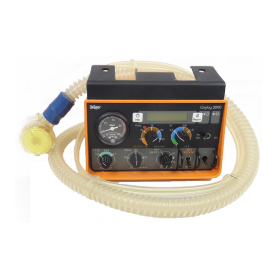
What's what Front view What's what Front view 10 9 1 Pressure gauge for airway pressure 12 Liquid crystal display for minute volume, warnings and advisory messages 2 Rotary knob for ventilation time ratio »T « infinitely adjustable from 1 : 3 to 2 : 1 13 Rotary knob for the ventilation frequency »Freq.«, infinitely adjustable from 5 to 40 1/min. - Page 41 What's what Rear view Rear view 1 Compartment for internal power supply: pack of six batteries, either NiCd or alkaline manganese...
- Page 42 What's what Right-hand side view Right-hand side view 1 Bracket for mounting unit in vehicles and for hanging unit from wall rails and horizontal tubes up to 38 mm diameter 2 Connector for external power supply (power supply unit or on-board supply with converter) 3 Connector for O , 2.7 to 6.0 bar 4 Connectors for flow measuring hoses...
-
Page 43: Technical Data
Technical Data Technical Data Ambient conditions Operation –18 to 50 °C Temperature Atmospheric pressure 600 to 1200 hPa Humidity 30 to 95 % rel. humidity Storage –18 to 70 °C Temperature Atmospheric pressure 600 to 1200 hPa Humidity 10 to 95 % rel. humidity Performance data Operational parameters Control principle... - Page 44 Technical Data Spontaneous breathing data Response pressure of demand valve approx. –1 mbar Max. delivery at –4 mbar 100 L/min Sensitivity of synchronization for SIMV 4 L/min for SIPPV 3 L/min Compliance with 1.5 m ventilation hose <1.0 mL/mbar with 3.0 m ventilation hose <1.2 mL/mbar Inspiratory resistance <6 mbar/L/s...
- Page 45 Technical Data Leakage Warning when the expiratory tidal volume drops below 60 % of the inspiratory tidal volume. The »Leakage« warning is not active in CPAP mode. Apnea Only active in CPAP mode. Alarm is activated if no change in breathing phases is detected within a 25 second time span.
- Page 46 Approx. 45 minutes without mixing (No Air Mix) Approx. 90 minutes with mixing (Air Mix) 12 V ±1 V DC Input voltage for Oxylog 2000 Connection for external power supply 12 V / 24 V / 28 V DC...
- Page 47 Technical Data Current consumption 700 mA to 1600 mA Protected by an internal micro-fuse to T 3,15A IEC 127 – 20 °C to +50 °C Temperature range Humidity 0 to 95 % rel. humidity (non-condensing) Electromagnetic compatibility EMC Tested to EN 60601-1-2 and EN 794-3 (36, 101) 10 V/m Classification Class IIb...
-
Page 48: Description Of Operating Principles
Description of operating principles Symbols for pneumatic components Description of operating principles PEEP Insp./Exsp. 100%O 50%O ∆ Air Mix/ No Air Mix IPPV/ SIMV/CPAP Flow Symbols for pneumatic components Filter Non-return check valve Pressure regulator Pressure limiting valve, variable Pressure limiting valve, with fixed setting 2/2-way valve, pneumatically controlled 3/2-way valve, electrically controlled Injector... -
Page 49: Gas Supply
Description of operating principles Gas supply IPPV/SIMV / SIMV PEEP Insp./Exsp. 100%O 50%O ∆ Air Mix/ No Air Mix IPPV/ SIMV/CPAP Flow Gas supply The O gas supply (or medical gas) is purified by filter 1 The controlled 2/2-way valve 21 prevents the inspiratory and regulated by pressure regulator 2 to a constant gas from escaping to the mechanical PEEP valve 8. -
Page 50: Cpap
Description of operating principles CPAP PEEP Insp./Exsp. 100%O 50%O ∆ Air Mix/ No Air Mix IPPV/ SIMV/CPAP Flow CPAP The gas flow to demand valve 6 is released by the 3/2-way valve 4 and monitored by pressure sensor 5. Inspiration / Expiration Controlled by the patient's inspiratory effort, demand valve 6 supplies the appropriate volume to the patient. -
Page 51: Abbreviations And Symbols
Abbreviations and symbols Abbreviations and symbols Air Mix Mixture of O and ambient air (= approx. 60 vol.% O CPAP Continuous Positive Airway Pressure – Breathing with positive airway pressure Cardio-pulmonary resuscitation IPPV Intermittent Positive Pressure Ventilation Body weight in kg Minute volume, L/min No Air Mix is not mixed with ambient air (= 100 vol.% O... -
Page 52: Appendix
The flow generates a pressure drop in the sensor which is measured via two pressure measuring hoses in Oxylog 2000. The pressure drop is proportional to the flow. The expiratory minute volume is calculated from the measured expiratory flow and indicated. -
Page 53: Order List
ANSI C73 5-15P (Japan) complete Power supply unit 230 V, 50 Hz 84 12 856 To supply the Oxylog 2000 from a central Mains plug, standard: BS 1363 (UK) piping system via a distributor and separate Power supply unit 240 V, 50 Hz 84 12 828 connecting hose. - Page 54 Order List Name Order No. cylinder, steel, 2 L/200 bar, B 02 351 PIN index, filled cylinder, steel, 2,5 L/200 bar, B 03 582 PIN index, filled cylinder, steel, 3 L/200 bar, B 02 531 PIN index, filled pressure reducer Wall bracket for carrying system 2000 AB 40 450 Sujektor 2000 secretion extractor...
-
Page 55: Index
Index Index bbreviations............. 51 iCd battery pack..........21, 36 Accessories..............3 NiCd battery pack, charging........24 Alarm, ”Main supply down”.........33 NiCd battery pack, fitting..........38 Alarm, "Paw high"............31 Alarm, "Paw low"............31 bserve safety notes........... 3 Alarm, "Upstream pressure low” ........ 32 Operating principles, description........ - Page 56 These Instructions for Use apply only to Oxylog 2000 3.n with Serial No.: If no Serial No. has been filled in by Dräger these Instructions for Use are provided for general information only and are not intended for use with any specific machine or device.
Need help?
Do you have a question about the Oxylog 2000 and is the answer not in the manual?
Questions and answers