Table of Contents
Advertisement
Quick Links
®
Oxylog
2000 plus Pocket Guide
Software version 1.n
The Oxylog 2000 plus Pocket Guide is not a replacement
or substitute for the Instructions for Use. Any use of the
device requires full understanding and strict observation
of the Instructions for Use. The user must be familiar with
the device according to the national and local laws and
recommendations. There will be no exchange of the
Pocket Guide when the product is updated/upgraded.
Advertisement
Table of Contents

Related Manuals for Dräger Oxylog 2000 plus


Summary of Contents for Dräger Oxylog 2000 plus
- Page 1 The Oxylog 2000 plus Pocket Guide is not a replacement ® Oxylog 2000 plus Pocket Guide or substitute for the Instructions for Use. Any use of the device requires full understanding and strict observation Software version 1.n of the Instructions for Use. The user must be familiar with the device according to the national and local laws and recommendations.
-
Page 3: Table Of Contents
Index Front panel with all options ........6-7 Side view, right / Rear view . - Page 4 Index Determining the approximate pneumatic operating time for the Oxylog® 2000 plus .....22-23 Operation / Settings Starting operation ......... . .24 Shutdown .
- Page 5 Index Alarms and Measured Values In the event of an alarm ........38 Setting alarm limits .
-
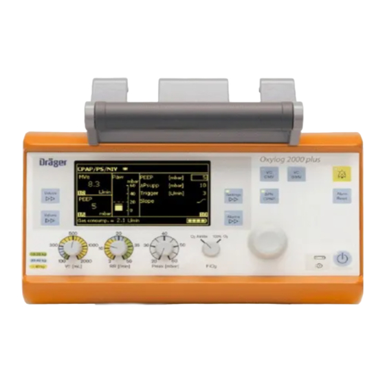
Page 6: Front Panel With All Options
Front panel with all options The Oxylog 2000 p us Pocket Guide is not a replacement or substitute for the Instructions for Use. Any use of the device requires full understanding and strict observation of the Instructions for Use. - Page 7 Front panel with all options A Screen with screen pages for the specific application K Display symbols for the power supply Charge status of the internal battery B Key Alarms for setting and displaying alarm Mains power supply connected limits L Central rotary knob for making selections / C Key Settings for setting other ventilation...
-
Page 8: Side View, Right / Rear View
Side view, right A Emergency air intake B Screw to secure the battery compartment cover C Connectors for flow measuring hoses D Connectors for ventilation hose E Connector for medical gas hose F Socket for DC supply G Window for Infrared Data Association (IrDA) interface... - Page 9 Rear view A Filter cartridge for intake of ambient air B Rating plate...
-
Page 10: Preparation
Preparation Breathing Systems The Oxylog 2000 p us Pocket Guide is not a replacement or substitute for the Instructions for Use. Any use of the device requires full understanding and strict observation of the Instructions for Use. Reusable hose system A Breathing valve B Ventilation hose C Flow and pressure measuring hoses... -
Page 11: Assemble The Reusable Hose System
Assemble the reusable hose system 1 Place the diaphragm (B) in the breathing valve. Ensure that it is inserted correctly. 2 Fit the cover (A) and turn it approximately 90° clockwise to secure into position. 3 Push the flow sensor (C) into breathing valve. Note the preferred position as indicated by the groove. -
Page 12: Connect The Reusable Hose System
Preparation Connect the reusable hose system 1 Connect the ventilation hose (A) to the breathing valve. 2 Connect the flow measuring hoses (B) to the nozzles on the flow sensor. Note the different diameters. 3 Connect the flow measuring (C) hoses to the Oxylog 2000 p us. 4 Connect the ventilation hose (D) to the gas outlet on the Oxylog 2000 p us... -
Page 13: Connect The Disposable Hose System
Connect the disposable hose system 1 Connect the blue flow measuring hose (B) to the blue gas connector. 2 Connect the transparent flow measuring hose (A) to the other gas connector. 3 Connect the ventilation hose (C) to the gas outlet on the Oxylog 2000 p us When changing the ventilation hose system If the reusable ventilation hose system is to be used instead of a... -
Page 14: When Using A Bacterial Filter Or Hme
Preparation When using a bacterial filter or HME Connect the bacterial filter or HME to the angled connector. Bacterial filter or HME... -
Page 15: Connecting The Power Supply
Connecting the power supply Oxylog 2000 p us is designed to operate on power supplies with different voltages: • DC voltage from the on-board power supply: Via DC/DC converter ° With AC/DC power pack ° • With rechargeable battery (specified Smart Battery) Internal supply with rechargeable battery Installing the battery 1 Insert a fully charged battery into the battery compartment (A). -
Page 16: Charging The Battery
Preparation Charging the battery The green lamp (B ) lights up when the battery is actively charging. A three colored indicator (A) lights up to show the current Ox ylo g 2000 plus charge status of the internal battery: • Green: when the battery has been fully charged. •... -
Page 17: Indication Of Battery Capacity / Battery Operation
Indication of battery capacity / battery operation The remaining capacity of the battery is indicated by Oxylog 2000 p us in 25% increments in the lower right section of the information window when power is ON. The capacity indication is overwritten if higher priority messages are activated. -
Page 18: External Power Supply
Preparation External power supply External power supply from mains power (AC/DC power pack) 1 Connect the mains plug (A) to the mains outlet. 2 Connect the DC plug (B) to the DC connector on the Oxylog 2000 p us O xylog 2000 plus Oxylog 2000 p us 3 When the is connected to an external supply, the... - Page 19 24 V DC (12 V, 24 V, 28 V DC). 28 V DC Oxylog 2000 plus 1 Plug the large connector (A) of the DC/DC converter into the on-board supply. 2 Plug the small connector (B) into the DC connector of the...
-
Page 20: Connecting The Gas Supply
Preparation Connecting the gas supply from an O cylinder Connecting the gas supply supply from an O cylinder 1 Use a full O cylinder. 2 Connect the pressure reducer (270 to 600 kPa delivery pressure, 500 kPa nominal pressure) to the O cylinder. -
Page 21: Supply From A Piped Medical Gas System
Supply from a piped medical gas system Oxylog 2000 p us 1 Connect the O medical gas hose (A) to the 2 Connect the gas hose (B) to the O terminal unit until the supply of O is confirmed. Preparation... -
Page 22: Determining The Approximate Pneumatic Operating Time For The Oxylog® 2000 Plus
Preparation Determining the approximate pneumatic operating time for the Oxylog® 2000 p us The pneumatic operation time increases when Oxylog 2000 p us operates with O AirMix, as ambient air is drawn into the device. The amount of gas from the high-pressure supply, which is currently being consumed, is indicated by the Oxylog 2000 p us in the lower left section of the information window in L/min. - Page 23 Determining the approximate pneumatic operating time for the Oxylog® 2000 p us Example for supply of medical gas: • Cylinder pressure measured on the pressure gauge of the pressure reducer: 20,000 kPa (200 bar) • Liquid capacity of the O cylinder: 2.1 L Supply of medical gas: 2.1 L x 20,000 kPa = approximately 420 L...
-
Page 24: Operation /Settings
Operation /Settings Starting operation The Oxylog 2000 p us Pocket Guide is not a replacement or substitute for the Instructions for Use. Any use of the device requires full understanding and strict observation of the Instructions for Use. Switch ON •... -
Page 25: Shutdown
Shutdown After disconnecting the patient switch the ventilator OFF: 1 Press the key (A) for approximately 3 seconds. The yellow lamp flashes and ventilation is terminated by the device. 2 Press the rotary knob (B) to acknowledge the alarm Ox ylo g 2000 plus !!! Confirm device OFF with rotary knob. -
Page 26: Perform Device Check
Operation /Settings Perform device check Oxylog 2000 plus Connect the test lung Switch ON 2 Press the rotary knob (A) to 1 Connect the angled adapter (A) to 1 To switch ON briefly press confirm, before the bar is full. the breathing valve. -
Page 27: Ventilation Controls
Ventilation controls Selecting the ventilation mode 1. Press the appropriate ventilation mode key (A) for approximately 3 seconds. Oxylog 2000 plus 1 Press the appropriate ventilation mode key (A). 2 Press the rotary knob (B) to confirm. The selected ventilation mode will be activated. -
Page 28: Preparing Ventilation Mode
Operation /Settings Preparing ventilation mode Set ventilation parameters 1 Set the required control below the display. 2 Select, set and confirm a parameter on the display with the rotary knob. The former settings are retained if confirmation is not received within 15 seconds. -
Page 29: Available Ventilation Modes
Available ventilation modes Available ventilation modes • VC-CMV / VC-AC olume ontrolled - ontrolled Mandatory entilation with PEEP. olume ontrolled - ssist ontrol with PEEP. • VC-SIMV (Optionally with Pressure Support) Volume Controlled - Synchronized Intermittent Mandatory Ventilation with PEEP. •... -
Page 30: Vc-Cmv / Vc-Ac
Operation /Settings VC-CMV / VC-AC VC-CMV – Volume Controlled - Controlled Mandatory Ventilation. Plateau time Volume-controlled ventilation with fixed mandatory minute volume MV, Tplat set with tidal volume VT and respiratory rate RR. plat PEEP Set the ventilation pattern with the controls below the display: •... -
Page 31: Trigger (Vc-Ac)
Trigger (VC-AC) Activating/setting the trigger 1 Press the key Settings (A) until the trigger parameter is displayed. 2 Select the line Trigger on the display and then set and confirm Ox ylo g 2000 plus the value with the rotary knob. Small value = high sensitivity. -
Page 32: Vc-Simv (Optional Ps)
Operation /Settings VC-SIMV (optional PS) VC-SIMV - Volume Controlled - Synchronized Intermittent Mandatory Pressure support PS Ventilation rapid slow For patients with inadequate spontaneous breathing, or for patients who rise time rise time PEEP are to be weaned gradually. Fixed mandatory minute volume MV is set with tidal volume VT and Trigger window ventilation respiratory rate RR. - Page 33 VC-SIMV (optional PS) Pressure support (optional) The following can also be set on the display for VC-SIMV / PS: • Setting on page 1: Pressure support ΔPsupp above PEEP. • Setting on page 2: Pressure rise time Slope flat ramp = long pressure rise time medium ramp = medium pressure rise time steep ramp = short pressure rise time.
-
Page 34: Spncpap (Optional Ps) (Optional Niv)
Operation /Settings SpnCPAP (optional PS) (optional NIV) SpnCPAP - Continuous Positive Airway Pressure Set the ventilation pattern with the controls below the display: • Maximum airway pressure Pmax. • O setting FiO Pressure support (optional) The following can additionally be set on the display for SpnCPAP / PS: •... -
Page 35: Spncpap (Apnea Ventilation)
SpnCPAP (Apnea Ventilation) Apnea back-up ventilation is only applicable when using the SpnCPAP Pmax mode. In the event of an apnea, the ventilator will automatically activate volume controlled mandatory ventilation (VC-CMV). Setting apnea ventilation Apnea alarm time Tapn On the display: Start Flow apnea ventilation... -
Page 36: Niv - Non-Invasive Ventilation (Optional)
Operation /Settings NIV – Non-Invasive Ventilation (optional) NIV (optional) can only be activated as a supplementary function in the pressure controlled ventilation modes SpnCPAP and SpnCPAP / PS. Mask leakages are detected by the device, compensated and included in the measured values for VTe and MVe. The leakage alarm is inactive. •... -
Page 37: Display Operating Controls
Display operating controls A Values key; to change screen pages in the "Measured Values" window, to display MVe or VTe. B Values key; to change screen pages in the "Measured values" Ox ylo g 2000 plus window, to display the measured values. C Settings key;... -
Page 38: Alarms And Measured Values
Alarms and Measured Values In the event of an alarm The Oxylog 2000 p us Pocket Guide is not a replacement or substitute for the Instructions for Use. Any use of the device requires full understanding and strict observation of the Instructions for Use. •... -
Page 39: Setting Alarm Limits
Setting alarm limits To set alarm limits for MV and RRsp • Press the key Alarms (A). Display example Alarms screen with variable alarm limits: = lower alarm limit. Ox ylo g 2000 plus = upper alarm limit. Alarm Range 2 to 41 L/min 0.5 to 40 L/min RRsp... -
Page 40: Displaying Other Measured Values
Alarms and Measured Values Displaying other measured values MVe / VTe window A Parameter measured. B Measured value. C Unit of measure. D Page number. Values window In the values window five different values can be displayed. To switch between the values: •... -
Page 41: Trouble Shooting
Alarm - Cause - Remedy The Oxylog 2000 p us Pocket Guide is not a replacement or substitute for the Instructions for Use. Any use of the device requires full understanding and strict observation of the Instructions for Use. Oxylog 2000 p us classifies alarm messages according to three priority !!! Warning High priority alarm message levels and identifies these accordingly with the aid of exclamation marks: !! Caution... -
Page 42: Messages In The Alarm Window
Trouble Shooting Messages in the alarm window Alarm Cause Remedy !!! Apnea Spontaneous breathing by the patient Ventilate in VC-CMV mode. has failed, or disconnection. Ensure that hose connections are tight. Faulty flow sensor. Replace flow sensor. !!! Apnea ventilation The ventilator has automatically Check ventilation mode. - Page 43 Messages in the alarm window Alarm Cause Remedy !!! Confirm device OFF has been pressed for 3 seconds. To switch OFF: confirm with the rotary knob. with rotary knob To continue ventilation, press key again. !!! Device failure Technical defect. Contact your local DrägerService for additional support.
- Page 44 Trouble Shooting Messages in the alarm window Alarm Cause Remedy !! High respiratory rate Patient breathes at a high Check patient's condition, check ventilation spontaneous rate. pattern, correct alarm limit RRsp if necessary. !! Int. battery charging inop Technical defect. Contact your local DrägerService for additional support –...
- Page 45 Messages in the alarm window Alarm Cause Remedy !!! Leakage (not in NIV) The measured expiratory tidal volume VTe Repair leaks in hose system and possibly in is approximately 40% lower than the the tube. inspiratory value. Use new flow measuring hoses. Faulty flow sensor.
- Page 46 Trouble Shooting Messages in the alarm window Alarm Cause Remedy !!! MV low The minute volume MV has dropped Check patient's condition, check ventilation below its lower alarm limit. pattern, adjust alarm limits if necessary. Leak in exhalation system. Ensure connections in exhalation system are tight.
- Page 47 Messages in the alarm window Alarm Cause Remedy !!! Paw high The alarm limit Pmax for the airway pressure Check patient's condition, check has been reached. Patient "fights" the ventilation pattern, adjust alarm ventilator, coughing. limits if necessary. Ventilation hose kinked, or obstructed. Check hose system, breathing valve and tube.
- Page 48 Trouble Shooting Messages in the alarm window Alarm Cause Remedy !! Paw measurement inop Fault in flow measurement hoses. Ensure hose system for loose connections. Ensure flow measurement hoses are connected correctly. Technical defect. Contact your local DrägerService for additional support – restricted operation is now possible.
-
Page 49: Error Messages During The Device Check
Error messages during the device check Message in the Cause Explanation/Remedy alarm window No communication Device defective. Contact your local DrägerService control- / charge-board System leakage Leak in ventilation hose system and/or test lung. Check hoses, breathing valve, flow sensor and test lung for leaks and replace if necessary. -
Page 50: Messages In The Information Window
Trouble Shooting Messages in the information window Message Cause Explanation/Remedy RR = 12 per min or Change in Ti, RR or VT VT = 800 mL in ventilation mode VC-SIMV. I : E = 1 : 1.5 Flow = 15 L/min RR = 12 per min or Change in I:E, RR or VT in VT = 800 mL... -
Page 51: Notes
Notes:... - Page 52 REGION EUROPE SOUTH REGION ASIA / PACIFIC HEADQUARTERS Dräger Médical S.A.S. Draeger Medical South East Asia Pte Ltd Drägerwerk AG & Co. KGaA Moislinger Allee 53–55 Parc de Haute Technologie d’Antony 2 25 International Business Park 25, rue Georges Besse #04-27/29 German Centre 23558 Lübeck, Germany 92182 Antony Cedex, France...
Need help?
Do you have a question about the Oxylog 2000 plus and is the answer not in the manual?
Questions and answers