
Related Manuals for Dräger Narkomed 2B


Summary of Contents for Dräger Narkomed 2B
- Page 1 North American Dräger Operator’s Instruction Manual Part Number: 4113918-002 Rev: B Date: 20 November 1998 © 1998 N.A.D., Inc. Narkomed 2B Anesthesia System...
-
Page 3: Table Of Contents
Narkomed 2B Operator’s Instruction Manual Table of Contents Section 1: Introduction Operator’s Responsibility for Patient Safety ........1-1 Limitation of Liability . - Page 4 Narkomed 2B Operator’s Instruction Manual Table of Contents Vaporizer Overview ........... . 5-2-1 Filling Systems .
- Page 5 Narkomed 2B Operator’s Instruction Manual Table of Contents Oxygen Monitoring Overview ........... 5-10-1 Monitor Displays .
- Page 6 Narkomed 2B Operator’s Instruction Manual Table of Contents Section 7: Specifications General ............7-1 Environmental .
-
Page 7: Section 1: Introduction
Section 1 Introduction Operator’s North American Dräger anesthesia products are designed to provide the Responsibility for greatest degree of patient safety that is practically and technologically Patient Safety feasible. The design of the equipment, the accompanying literature, and the labeling on the equipment take into consideration that the purchase and use of the equipment are restricted to trained professionals, and that certain inherent characteristics of the equipment are known to the trained operator. -
Page 8: Limitation Of Liability
Section 1 Introduction Limitation of North American Dräger’s liability, whether arising from or related to the Liability manufacture and sale of the products, their installation, demonstration, sales representation, use, performance, or otherwise, including any liability based upon North American Dräger’s product warranty, is subject to and limited to the exclusive terms of North American Dräger’s limited warranty, whether based upon breach of warranty or any other cause of action whatsoever, regardless of any fault attributable to North... -
Page 9: How This Manual Is Organized
AUDIBLE ALARM ENABLE THRESHOLD PRESSURE ALARM LIMIT How This Manual Is All users of the Narkomed 2B must read this manual completely before Organized using the machine. In order to make this document more convenient for future reference, it has been divided into several independent sections. -
Page 10: Conventions Used In This Manual
The following list of warnings and cautions apply to general operation and Cautions and maintenance of the Narkomed 2B. Warnings and cautions about installing and operating specific parts appear with those topics. WARNING: Any person involved with the setup, operation, or maintenance of the Narkomed 2B anesthesia system must be thoroughly familiar with this instruction manual. -
Page 11: Recommendations
Section 1 Introduction CAUTION: Although the Narkomed 2B is designed to minimize the effects of ambient radio-frequency interference, machine functions may be adversely affected by the operation of electrosurgical equipment or short wave or microwave diathermy equipment in the vicinity. -
Page 13: Section 2: General Description
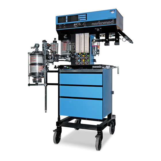
2B is a continuous flow anesthesia system. All Narkomed 2B machines are equipped with a monitoring system and pneumatic circuitry for delivering gases and anesthetic vapor. A front view of the Narkomed 2B is shown in the figure below. ALARM DATA... - Page 14 Diagonal Stripes Diagonal Stripes Gas Entry Via Gas from the hospital pipelines enters the Narkomed 2B through hoses Pipeline connected to indexed pipeline inlets located on the side of the flowmeter housing. The indexed connector system reduces the risk of delivering the wrong gas to a patient by preventing incorrect connection of gas pipes.
- Page 15 Section 2 General Description THREE-GAS FLOWMETER AND PRESSURE GAUGE ASSEMBLY COARSE FLOW TUBE (l/min) 1000 1000 1000 FINE FLOW TUBE (ml/min) INDICATOR FLOATS FLOW CONTROL VALVE FLOWMETER GUARD KNOB PIPELINE PRESSURE GAUGE CYLINDER PIPELINE PIPELINE PIPELINE CYLINDER CYLINDER CYLINDER PRESSURE GAUGE OP10006 When the machine is connected to an active pipeline supply, each gauge...
-
Page 16: Index
Section 2 General Description Gas Entry Via The Narkomed 2B can be equipped with a maximum of two oxygen and Cylinder Yokes two nitrous oxide cylinder hanger yokes. An additional yoke for an optional third gas is also available. To prevent a cylinder from being improperly connected, the yokes are labeled, color-coded, and keyed for gas-specific cylinders using the pin-indexed safety system. - Page 17 Section 2 General Description Cylinder Pressure Each cylinder gas circuit has a cylinder pressure gauge, located at the Gauges bottom of the flowmeter panel on the front of the machine (see the Flowmeter and Pressure Gauge Assembly figure earlier in this section.) Each gauge is labeled and color-coded for its respective gas.
- Page 18 Each flowmeter has a float indicator. To determine the flow rate, read the flowmeter scale at the center of the float. Low-Flow For low-flow anesthesia, the Narkomed 2B can be configured with low- Flowmeters flow, dual-tube flowmeters for oxygen and nitrous oxide. These...
- Page 19 The valve, when actuated, delivers an unmetered oxygen flow of approximately 55 l/min directly to the Narkomed 2B’s fresh gas common outlet. The SYSTEM POWER switch does not have to be in the ON position to use the oxygen flush.
- Page 20 Section 2 General Description Fresh Gas Outlet The fresh gas outlet delivers the fresh gas mixture (consisting of oxygen, nitrous oxide, optional gases, and vapors of a liquid anesthetic) to the patient breathing system. It is located on the front of the anesthesia machine.
- Page 21 Section 2 General Description Fresh Gas Outlet The fresh gas outlet, located on the front of the machine, delivers the (Canada) fresh gas mixture to the patient breathing system. The fresh gas mixture consists of oxygen, nitrous oxide, optional gases, and vapors of a liquid anesthetic.
- Page 22 Section 2 General Description Fresh Gas The optional fresh gas adapter allows the Narkomed 2B to monitor the Oxygen Sensor fresh gas oxygen concentration when using a nonrebreathing circuit Adapter (other than a Bain Circuit). The fresh gas adapter fits securely into the fresh gas outlet of the anesthesia machine.
-
Page 23: Vaporizers
A zero stop prevents damage to the flow control valve seat. Vaporizers The Narkomed 2B can be equipped with up to three Vapor 19.1 vaporizers for administering liquid anesthetics. Exclusion System A cam and lever interlock system, incorporated into the vaporizer bank, prevents more than one vaporizer from being activated at a time. -
Page 24: Absorber
Section 2 General Description Absorber The absorber is a dual-canister system for absorbing exhaled carbon dioxide in the rebreathing circuit of the anesthesia machine. It incorporates an adjustable pressure limiter (APL) valve, a breathing system pressure gauge, a fresh gas line, and connections for sensing the following: breathing pressure, respiratory volume, frequency, and oxygen concentration. - Page 25 Section 2 General Description The absorber system permits spontaneous, manually assisted, or automatic ventilation of the patient. The absorber incorporates a manual/automatic selector valve, which allows you to select either manual or automatic ventilation. An absorber with a positive end expiratory pressure (PEEP) valve is also available.
- Page 26 Section 2 General Description Canisters Each absorber unit contains two interchangeable transparent plastic canisters which house the absorbent. The absorbent, soda lime or barium hydroxide lime, can be purchased in either loose granular or prepacked cartridge form. Dust Cup A removable, transparent plastic cup below the bottom assembly collects absorbent dust and excess moisture which could cause increased flow resistance in the system.
-
Page 27: Bain Circuit Adapters
Section 2 General Description Bain Circuit Two types of Bain circuit adapters are available. One mounts to the Adapters absorber; the other mounts to the absorber pole. Absorber Mount The absorber-mounted Bain circuit adapter, shown in the following illustration, mounts onto the manual/automatic selector valve of the absorber system. - Page 28 Section 2 General Description Pole Mount The pole-mounted Bain Circuit adapter, shown in the following illustration, mounts on the absorber pole. It may be supplied with or without a positive end-expiratory pressure (PEEP) valve. 19 MM SCAVENGER HOSE OXYGEN SENSOR (CONNECTS TO 19MM TERMINAL ON REAR BREATHING...
-
Page 29: Scavenger Systems
Section 2 General Description Scavenger Systems The Narkomed 2B can be equipped with two kinds of scavenger systems, permitting the best match with the hospital’s waste gas disposal system. Open Reservoir The open reservoir scavenger is used with suction (vacuum) waste gas Scavenger disposal systems. - Page 30 Section 2 General Description Scavenger The scavenger interface for passive systems is used with Interface for nonrecirculating HVAC systems (also called exhaust systems). This Passive Systems scavenger is a “closed” system, using a spring-loaded valve for positive pressure relief. WARNING: Do not use this device with a waste gas disposal system capable of applying a negative pressure to the scavenger interface (a suction or vacuum waste gas disposal system).
-
Page 31: Av2+ Ventilator
The pressure of the supply gas must be between 40 and 60 psi. The ventilator will not function properly if this pressure drops below 32 psi. Electrical power is supplied by the Narkomed 2B’s AC power source, or, in event of AC power failure, by the backup battery. -
Page 32: Main Switch Panel
The main switch panel is located between the ventilator bellows and flowmeter bank. System Power The SYSTEM POWER switch on the Narkomed 2B has two positions: ON Switch and STANDBY. In the ON position, the gas (pneumatic) and electric power circuits are actuated, and the green LED indicator adjacent to the switch illuminates. - Page 33 Section 2 General Description O SUPPLY PRESSURE RED O2 SUPPLY BATTERY PRESSURE TEST PUSH LOW INDICATOR BUTTON POWER FAIL BATTERY BATTERY TEST SYSTEM YELLOW AC POWER POWER FAIL SWITCH INDICATOR YELLOW BATTERY LOW INDICATOR STANDBY SYSTEM POWER GREEN BATTERY TEST INDICATOR OP20050 Oxygen Supply...
-
Page 34: Power Supply System
Section 2 General Description Power Supply The Narkomed 2B is equipped with a central power supply for the System ventilator, alarm system, and monitoring system. When in use, the Narkomed 2B must be plugged into an AC outlet. Convenience The Narkomed 2B is equipped with four convenience receptacles, Receptacles mounted on the under side of the rear of the monitor bank. - Page 35 When the hospital’s emergency generator comes on-line (or when a disconnected power cord is reconnected), the Narkomed 2B automatically switches back to AC power and recharges its battery. The battery charging system charges the battery any time the power cord is connected to an active AC power source.
-
Page 36: System Interface Panel
AC power is restored. NOTE: If the Narkomed 2B’s power cord is not plugged into an active AC outlet for a period of 30 days or more, the backup battery may become depleted. Plugging the power cord into an active AC outlet for approximately 16 hours will recharge a depleted battery. -
Page 37: Monitoring System
The anesthesia machine’s monitoring system integrates the functions of the electronic monitors and organizes information from these monitors onto two screens. The screens are located on the front panel of the machine. The Narkomed 2B monitors the following measurements: • oxygen concentration • breathing pressure • respiratory volume The anesthesia machine also monitors key anesthesia system functions, such as oxygen supply pressure and backup battery status. -
Page 38: Alarm System
Prompt Awareness Required NOTE: The Narkomed 2B may also serve as an alarm interface for external devices that adhere to the NAD Vitalink protocol. For information about alarms associated with a Vitalink device, see the documentation for that device. 2-26... -
Page 39: Manual Sphygmomanometer
Alarm Silence key on the control key panel (labeled with a crossed-out speaker). If the primary speaker on the Narkomed 2B fails, a backup speaker is activated. The backup speaker has a tinny sound to distinguish it from the primary speaker. -
Page 40: O.r. Data Manager
Section 2 General Description ® O.R. Data Manager The O.R. Data Manager is an electronic data management system for (optional) acquiring, storing and retrieving information. It consists of a central processing unit with disk drive and a keyboard for entering and editing data. -
Page 41: Section 3: Daily Checkout
Section 3 Daily Checkout Daily Checkout Before operating the Narkomed 2B, the following checkout procedure Procedure must be performed to make sure the machine is ready for use. This is a recommended procedure. Follow your institution’s policies for specific checkout procedures. If the anesthesia system fails any procedures identified by an asterisk (*), do not use the machine. - Page 42 Section 3 Daily Checkout Emergency Verify that backup ventilation equipment is available and Ventilation Equipment functional. Verification High Pressure Check the oxygen cylinder supplies. System Verification Disconnect all pipeline gas supply hoses and drain the system. Close the oxygen cylinder valve and remove the cylinder from the yoke.
- Page 43 Section 3 Daily Checkout *10. Check additional (optional) gas cylinder supplies. With the cylinder closed, open the flow control valve of the associated gas until the cylinder and pipeline pressure gauges (air only) indicate zero pressure. Close the cylinder valve and remove the cylinder from the yoke.
- Page 44 Section 3 Daily Checkout Pipeline Supply *11. Pipeline Supply Verification System Verification Inspect the supply hoses for cracks or wear. Connect the appropriate hospital pipeline supply hoses from the wall outlet fittings to the pipeline inlet connectors. Check for sufficient pipeline pressure readings for each gas on the pipeline pressure gauges located below the flow control valves.
- Page 45 Section 3 Daily Checkout Close the cylinder supplies and deplete the pressure from the system. OFPD Verification *15. Check the oxygen failure protection device. With all gases available on the machine set to a flow of about 4 l/min, close the oxygen supply by disconnecting the oxygen pipeline supply hose and closing the oxygen cylinder(s).
- Page 46 Section 3 Daily Checkout As an alternate test, press the oxygen flush button with the Bain circuit’s patient port open to the atmosphere. The high flow of gas through the Bain circuit’s inner tube will draw in gas from the outer tube.
- Page 47 Section 3 Daily Checkout WARNING: Absorbent is caustic and is a strong eye, skin, and respiratory tract irritant. When emptying the absorber dust cup, take care not to spill its caustic contents. NOTE: When changing the CO absorbent, take care not to chip or crack the absorbent canister.
- Page 48 Section 3 Daily Checkout Turn the SYSTEM POWER switch to the STANDBY posi- tion. Turn the vaporizers to 0% concentration. Interconnect the 22 mm ports of the inspiratory and expiratory valves with a 22 mm breathing hose. Set the manual/automatic selector valve to BAG. Close the APL valve by turning the knob fully clockwise to its stop position.
- Page 49 Section 3 Daily Checkout Check for moisture accumulation in the breathing and scavenger hoses. Remove any moisture found. Verify the safe performance of the open reservoir scavenging system. With the scavenging system properly installed and operating, test for positive and negative pressure relief.
- Page 50 Section 3 Daily Checkout The flow of oxygen must now exit through the relief ports located on top of the canister. The absorber system’s breathing pressure gauge must indicate a pressure less than 5 cm H After the test, adjust the scavenger needle valve to a flowmeter indication halfway between the two white lines.
- Page 51 Section 3 Daily Checkout Manual and *26. Test the ventilator. Automatic Ventilation Systems Check for proper pressure and flow at the Y-piece during the inspiratory and expiratory phases. Turn the SYSTEM POWER switch and ventilator power switch to their ON positions.
- Page 52 Section 3 Daily Checkout *28. Test the alarm functions for all monitors. Simulate alarm conditions and check for appropriate alarm signals. System Flush Flush the system with 100% oxygen by pressing the oxygen flush button. Fresh Gas Oxygen If the optional fresh gas oxygen sensor adapter is installed, make Sensor Adapter sure the fresh gas hose connection is intact and not occluded.
-
Page 53: Section 4: Preuse Checkout
Perform the following abbreviated checkout procedure when the Procedure Narkomed 2B is used in successive cases. It may be performed only after the initial daily checkout procedure given in Section 3 was performed. This is a recommended procedure. Follow your institution’s policies regarding specific checkout procedures. - Page 54 Section 4 Preuse Checkout Make sure a 22 mm patient breathing circuit is connected between the inspiratory and expiratory valves on the absorber. Make sure a 22 mm breathing hose is connected between the ventilator hose terminal and the manual/automatic selector valve breathing hose terminal.
- Page 55 Section 4 Preuse Checkout APL Valve Check the APL valve to be sure it can relieve excess gas from the breathing system into the scavenger system. To check the APL valve’s flow resistance: Set the manual/automatic selector valve to BAG. Remove the bag from the swivel arm bag mount.
- Page 56 Section 4 Preuse Checkout Attach the supplied test terminal to the breathing bag mount. Connect a sphygmomanometer squeeze bulb (available from North American Dräger) to the hose barb on the test terminal. Pump the squeeze bulb by hand until the breathing system pressure gauge indicates pressure of at least 50 O (not to exceed 80 cmH Observe the pressure drop at the breathing system...
- Page 57 Section 4 Preuse Checkout Set the absorber’s manual/automatic selector valve to BAG. Turn the APL valve control knob fully counterclockwise. Verify that the suction waste gas disposal system is active. Adjust the scavenger needle valve to a flowmeter indication between the two white lines. Close all flow control valves on the anesthesia system.
- Page 58 Section 4 Preuse Checkout Make sure a 19 mm scavenger hose is connected between the bottom of the absorber pole and the scavenger interface. Check for moisture accumulation in the breathing and scavenger hoses. Remove any moisture found. Short circuit the absorber’s inspiratory and expiratory valves with a 22 mm breathing hose.
- Page 59 Section 4 Preuse Checkout The pressure gauge must indicate a pressure over 30 O when the bellows completes its downward travel. The pressure should not exceed 3 cmH O at the end of the expiratory phase when the bellows completes its upward travel.
- Page 60 Section 4 Preuse Checkout Final Position When the daily checkout procedure is complete, verify that: all vaporizers are off (the handwheels are set to zero) the APL Valve is open (fully counterclockwise) the manual/automatic switch is set to BAG all flowmeters indicate 0 (or minimum) the patient suction is level adequate the breathing system is ready to use (the bag is in place and all hoses are connected properly)
-
Page 61: Section 5: Operation
2. Connect the other end of the supply hose to the appropriate functioning hospital pipeline supplies. 3. Check the pipeline pressure gauge on the front of the Narkomed 2B for sufficient pipeline pressure (50-55 psi). 5-1-1... -
Page 62: Connecting The Gas Cylinders
Section 5 - Operation Gas Delivery System NIST DISS BODY OPTION OPTION O2 DISS BODY O2 NIST GAS FITTING GAS FITTING AIR DISS BODY AIR NIST GAS FITTING GAS FITTING N2O DISS BODY N2O NIST GAS FITTING GAS FITTING O2 DISS NUT GAS FITTING AIR DISS NUT DISS NUT... - Page 63 Section 5 - Operation Gas Delivery System 2. Verify the presence and integrity of the two index pins below the gas inlet. WARNING: Check cylinder yokes for the presence of two index pins each time you attach a cylinder to the machine. 3.
-
Page 64: Connecting The Fresh Gas Hose
To connect the fresh gas hose, pull out the fresh gas locking bar located Fresh Gas Hose on the front of the Narkomed 2B to its extended position. Insert the 15 mm male fitting on the fresh gas hose into the 15 mm female terminal. -
Page 65: Vaporizer
Section 5 - Operation Vaporizer Overview The Vapor 19.1 adds an anesthetic gas to the fresh gas stream by producing a precisely metered amount of the vapor of a particular liquid anesthetic. The vaporizer is installed in the fresh gas line upstream of the patient breathing system (semi-closed, semi-open system). -
Page 66: North American Dräger Exclusion System
Section 5 - Operation Vaporizer OP10603 KEY INDEXED SAFETY SYSTEM OPEN FUNNEL FILLER North American A cam and lever exclusion (interlock) system incorporated into the vaporizer bank prevents more than one vaporizer from being activated at Dräger Exclusion System a time. The exclusion system requires all unused vaporizers to be locked in their zero percent positions. -
Page 67: Operating The Vaporizers
Section 5 - Operation Vaporizer PIVOT ARMS VAPOR MOUNT OP10609 Operating the Before each case, check the following items. Vaporizers 1. Make sure the vaporizer contains a sufficient amount of anesthetic agent as indicated in the sight glass. 2. Make sure the filling and draining valves are closed. For vaporizers with the key indexed safety system, make sure the sealing plug is properly fitted and locking screw is tight. -
Page 68: Filling The Vaporizer
Section 5 - Operation Vaporizer Turning the To turn the vaporizer off, turn the vaporizer handwheel to “0” (zero-point Vaporizer Off interlock) and make sure the button engages. Do not interrupt the fresh gas flow until you have turned off the vaporizer. NOTE: If you will not be using the vaporizer for a long period of time (longer than one month), or if the vaporizer will be... -
Page 69: Filling The Vaporizer During A Case
Section 5 - Operation Vaporizer Filling the Vaporizer If you must fill the vaporizer during a case, be extremely careful. While During a Case fresh gas is flowing and the vaporizer is turned on, the vaporizing chamber is pressurized. DO NOT open the inlet valve (or the screw of the safety filling device) under these circumstances —... - Page 70 Section 5 - Operation Vaporizer OP10622 INLET VALVE FILLING SPOUT MAX FILL LINE SIGHT GLASS DRAIN VALVE MIN FILL LINE 6. With the vaporizer in an upright position, pour the anesthetic agent into the funnel. As you pour the agent, observe the level through the sight glass.
- Page 71 Section 5 - Operation Vaporizer Filling Vaporizer The key indexed safety system employs a matching assembly to prevent With Key Indexed inadvertent use of the wrong agent in a Vapor 19.1 device. To fill a Safety System vaporizer with key indexed safety system, you must have the appropriate keyed bottle adapter for the anesthetic agent.
- Page 72 Section 5 - Operation Vaporizer 9. Watch the sight glass while the vaporizer is filling, and close the filler valve when the liquid level reaches the lower of the two marks at the upper end of the sight glass. The lower mark is the FULL mark;...
- Page 73 Section 5 - Operation Vaporizer FILLER VALVE KNOB OP10621A FILLER PORT LOCK SCREW KEYED FILLER PORT FILLER PORT PLUG KEYED SIGHT GLASS BOTTLE ADAPTER OVERFLOW LINE FULL LINE REFILL LINE DRAIN VALVE DRAIN PORT KNOB LOCK SCREW KEYED KEYED BOTTLE DRAIN PORT ADAPTER 5-2-9...
- Page 74 Section 5 - Operation Vaporizer HALOTHANE (RED) ENFLURANE (ORANGE) ISOFLURANE (PURPLE) SEVOFLURANE (YELLOW) OP10620 5-2-10...
-
Page 75: Draining The Vaporizer
Section 5 - Operation Vaporizer Draining the Before draining a vaporizer, identify the filling system on the device as Vaporizer one of the following: • Open funnel system • Key indexed safety system When you have identified the filling system, locate the appropriate procedure and read it entirely before draining the device. - Page 76 Section 5 - Operation Vaporizer Draining The key indexed safety system employs a matching pin-and-socket Vaporizer With assembly to prevent inadvertent use of the wrong agent in a Vapor 19.1 Key Indexed device. To drain a vaporizer with key indexed safety system valves, you Safety System must have the appropriate keyed bottle adapter for the anesthetic agent.
-
Page 77: Absorber System
Section 5 - Operation Absorber System REFER TO SEPARATE MANUAL 5-3-1... -
Page 79: Bain Circuit Adapter
Section 5 - Operation Bain Circuit Adapter REFER TO SEPARATE MANUAL 5-4-1... -
Page 81: Open Reservoir Scavenger
Section 5 - Operation Open Reservoir Scavenger Overview The open reservoir scavenger is intended for use with suction (vacuum) waste gas disposal systems. This scavenging approach applies a continuous suction to transfer waste gas from the scavenger to the disposal system. The open reservoir scavenger is an “open” system, which uses continually open relief ports to provide positive and negative pressure relief. -
Page 82: Connecting The Open Reservoir Scavenger System
Section 5 - Operation Open Reservoir Scavenger Connecting the The open reservoir scavenger system is installed on the Narkomed 2B Open Reservoir before shipping. The only thing you need to do before operating the Scavenger System scavenger is to make the hose connections. -
Page 83: Operating The Open Reservoir Scavenger System
Section 5 - Operation Open Reservoir Scavenger VENTILATOR BELLOWS W/22MM VENTILATOR HOSE TERMINAL RELIEF VALVE W/19MM SCAVENGER HOSE TERMINAL VENTILATOR 22MM BREATHING HOSE 19MM SCAVENGER HOSE 19MM SCAVENGER HOSE 19MM SCAVENGER VACUUM HOSE TERMINAL TERMINAL OP75123 Operating the Open Because the open reservoir scavenger’s reservoir canister is open to the atmosphere, it does not require spring-loaded relief valves. - Page 84 Section 5 - Operation Open Reservoir Scavenger Adjusting the You must properly adjust the waste gas flow rate to prevent waste gas Needle Valve contamination of the operating room. The needle valve wing nut regulates the waste gas exhaust flow. To adjust the needle valve: 1.
-
Page 85: Scavenger Interface For Passive Systems
Section 5 - Operation Scavenger Interface for Passive Systems Overview The Scavenger Interface for Passive Systems is intended for use with nonrecirculating HVAC systems (also called exhaust systems). This scavenging approach relies on the pressure of the waste gas itself to transfer the gas from the scavenger to the disposal system. -
Page 86: Operating The Scavenger Interface For Non-Active Systems
Section 5 - Operation Scavenger Interface for Passive Systems Operating the In a typical anesthesia circle system, waste gas exits form the breathing Scavenger Interface system APL or ventilator relief valves and passes through the scavenger for Non-active to the exhaust system. If the hospital exhaust system stopped Systems functioning (or if the path between the scavenger and the exhaust system becomes blocked), positive pressure would build up within the... -
Page 87: Main Switch Panel
INDICATOR OP20050 System Power The SYSTEM POWER switch on the Narkomed 2B has two positions: ON Switch and STANDBY. In the ON position the gas (pneumatic) and electric power circuits are activated and the green LED indicator adjacent to the switch is illuminated. -
Page 88: Testing The Battery
Section 5 - Operation Main Switch Panel Testing the Battery The backup battery system shall be tested daily. To test the battery: 1. Turn the SYSTEM POWER switch ON, and wait until the power-on diagnostic screen is no longer displayed. 2. -
Page 89: Av2+ Anesthesia Ventilator
The pressure of the supply gas must be between 40 and 60 psi. The ventilator will not function if this pressure drops below 32 psi. Electrical power is supplied by the Narkomed 2B’s AC power source, or, in event of AC power failure, by the backup battery. A fully charged battery can power the ventilator for approximately 30 minutes. -
Page 90: Activating The Ventilator
Section 5 - Operation AV2+ Anesthesia Ventilator INSPIRATORY FLOW GAUGE I:E RATIO CONTROL INSPIRATORY EXTENDED RANGE FLOW CONTROL ACCESS I:E RATIO DISPLAY VENTILATOR ON-OFF FREQUENCY CONTROL CONTROL FREQUENCY DISPLAY INSPIRATORY VENTILATOR FLOW 1:2.5 I:E RATIO FREQUENCY /min FAULT EXTENDED AV2+ RANGE INSPIRATORY PRESSURE LIMIT TIDAL VOLUME... - Page 91 Section 5 - Operation AV2+ Anesthesia Ventilator MANUAL/AUTOMATIC SELECTOR VALVE INTERFACE CABLE SELECTOR FITTING ON BREATHING SYSTEM SENSOR INTERFACE PANEL CONNECTOR OP05127 When the ventilator is activated, both pneumatic and electric power to the ventilator are turned on, and the monitoring system’s volume and pressure alarms are automatically enabled.
-
Page 92: Adjusting The Tidal Volume
Section 5 - Operation AV2+ Anesthesia Ventilator Using the The ventilator can be turned on and off with the selector lever on the Manual/Automatic manual/automatic selector valve (with the interface cable between the Selector Valve selector valve and interface panel properly connected). Lever NOTE: When you operate the lever, let it snap into position. -
Page 93: Setting The Inspiratory/Expiratory (I:e) Phase Time Ratio
Section 5 - Operation AV2+ Anesthesia Ventilator Setting the Use the I:E ratio control knob to set the inspiratory/expiratory (I:E) Inspiratory/ phase time ratio. The standard range of ratios is from 1:1 through 1:4.5, Expiratory (I:E) adjustable in increments of 0.5. Phase Time Ratio An extended range of ratios is also available which allows the setting of inverse I:E ratios. -
Page 94: Problem Resolution
Section 5 - Operation AV2+ Anesthesia Ventilator Problem Resolution P P R R O O B B L L E E M M P P O O S S S S I I B B L L E E C C A A U U S S E E R R E E M M E E D D Y Y Excessive PEEP Improperly adjusted... - Page 95 Section 5 - Operation AV2+ Anesthesia Ventilator P P R R O O B B L L E E M M P P O O S S S S I I B B L L E E C C A A U U S S E E R R E E M M E E D D Y Y Ventilator does not Selector switch on the...
-
Page 97: Monitoring System
Power-On Screen When you turn the SYSTEM POWER switch to the ON position, the Narkomed 2B performs extensive self-tests on its internal hardware. As these diagnostics are performed, each test and its result (PASS or FAIL) appear on the left-hand display screen, indicating the status of various components of the monitoring system. -
Page 98: Monitor Screens And Controls
Section 5 - Operation Monitoring System When you are ready to resume operation, press the key indicated on the left-hand screen. A serious fault was detected. The monitoring NONFUNCTIONAL system will not operate under this condition. Do not use the machine. Immediately notify a North American Dräger qualified technical service representative to correct the problem. - Page 99 Section 5 - Operation Monitoring System Right-Hand The right-hand screen displays the time, as well as numerical Screen measurements for oxygen concentration, breathing pressure, and respiratory volume. The most current measurements are always displayed on this screen, as long as the associated monitor is supplying information.
-
Page 100: Configuring The Anesthesia Machine
Section 5 - Operation Monitoring System Configuring the You can configure the following parameters on the Narkomed 2B: Anesthesia Machine – audio annunciator volume – current date – current time – serial Port A parameters NOTE: You can configure Port A only. It communicates using the Vitalink Communications Protocol. - Page 101 Section 5 - Operation Monitoring System Understanding When the Configure screen is displayed, the control keys function the Configuration according to the labels on the screen. Keys Label Configuration Function SELECT Selects a parameter on the Configure screen by highlighting it with a box Increases the value of the highlighted parameter Decreases the value of the highlighted...
-
Page 102: Controlling Continuous Audible Alarms
Section 5 - Operation Monitoring System Controlling You can silence and enable the Narkomed’s continuous audible alarms Continuous Audible with the top two system control keys, located next to the left-hand Alarms screen. NOTE: You can set alarm limits and control the respiratory volume and apnea alarms with the monitor control keys. -
Page 103: Working With Trace Data
Section 5 - Operation Monitoring System Working with The NARKOMED monitors breathing pressure. You can display the Trace Data breathing pressure waveform, or trace, on the Trace and Trend display area at the bottom of the left-hand screen. Displaying the Following power-up, the breathing pressure waveform is displayed on Trace the left-hand screen. -
Page 104: Working With Trend Data
Section 5 - Operation Monitoring System GAP IN TRACE REPRESENTS THRESHOLD DIVISION BETWEEN ALARM LIMIT CURRENT SWEEP AND PREVIOUS SWEEP CURRENT PREVIOUS SWEEP SWEEP CURRENT PREVIOUS SWEEP SWEEP OP20018 Working with The NARKOMED monitor records measurements for the following variables over time: percent oxygen, breathing rate, and minute volume. Trend Data You can display trend, or historical, data for these variables on the Trace and Trend display area at the bottom of the left-hand screen. - Page 105 Since the NARKOMED 2B starts trending available data on power-up, it rounds off the time scale labeling to the previous ten-minute increment for ease of reading. For example, if the NARKOMED 2B is powered-up and begins monitoring at 12:23, the left-most time mark will be 12:20.
-
Page 106: Working With Numerical Data
Section 5 - Operation Monitoring System As trending proceeds past one hour, the trend display adjusts the time scale as follows: When the graph fills up with trend data, the trend dis- play creates a new time scale that carries over only the most recent 50 minutes of data from the previous graph. -
Page 107: Oxygen Monitoring
Section 5 - Operation Oxygen Monitoring Overview Inspiratory oxygen concentration is measured with a dual galvanic cell sensor which is attached to the inspiratory valve dome. The sensor works by taking in oxygen, which initiates an electrochemical reaction within the oxygen sensor. The oxygen monitor reads the voltage produced by this reaction and translates it into an oxygen concentration measurement. -
Page 108: Monitor Displays
Section 5 - Operation Oxygen Monitoring Monitor Displays Information about the oxygen analysis is presented on the two monitor screens. • Left-Hand Screen—You can display the inspiratory oxygen trend on this screen by pressing the TREND key until the PERCENT OXYGEN graph appears. -
Page 109: Monitor Controls
Section 5 - Operation Oxygen Monitoring • Right-Hand Screen—The numerical value for inspiratory oxygen is shown on the right-hand screen. To the right of this number, in smaller type, are the high and low oxygen concentration alarm limits. OXYGEN HIGH OXYGEN CONCENTRATION CONCENTRATION ALARM LIMIT VALUE... -
Page 110: Setting Alarm Limits
Section 5 - Operation Oxygen Monitoring Setting Alarm The oxygen alarm limits are automatically set to the defaults at power- Limits up. You can adjust the alarm limits within specified ranges. The valid values and the defaults are shown in the following table: Alarm Limit Default Possible Values... -
Page 111: Calibrating The Oxygen Sensor
Section 5 - Operation Oxygen Monitoring Calibrating the To calibrate the oxygen sensor correctly, make sure it is exposed only to Oxygen Sensor room air during the entire calibration period. You should calibrate the oxygen sensor as part of the daily preoperative setup of the anesthesia equipment. - Page 112 Oxygen Exposure Typical Calibration Time 10 seconds > 21% up to 50 seconds When the Narkomed 2B has successfully completed calibration, pull the inspiratory valve dome plug and reinsert the sensor assembly. 5-10-6...
-
Page 113: Unsuccessful Calibration
02 SENS DISC, 02 NOT CAL, and 02 SENS DISC. If this happens, reconnect the sensor cord to the interface panel on the Narkomed 2B and press the O2 CAL key again. 5-10-7... - Page 114 If the oxygen sensor is improperly calibrated, it can cause inaccurate measurements. When a calibration gas mixture is excessively rich or lean in oxygen, the Narkomed 2B will not complete an attempted calibration; however, if the calibration gas is rich or lean but is within certain limits, the Narkomed 2B will complete the calibration.
-
Page 115: Oxygen Alarm Messages
Advisory message O2 SENS ERR appears on the central alarm display. During oxygen sensor calibration, the Narkomed 2B also checks the sensor’s output against a range of acceptable output voltages. There are three possible causes for deviation from within this range. -
Page 116: Low Oxygen Supply Whistle
O2 SENS ERR message normally used for an invalidated calibration. Low Oxygen Supply If the Narkomed 2B is configured to do so, it sounds a 7-second whistle Whistle when the oxygen supply drops too low to properly pressurize the fresh gas circuit (below about 37 psi). -
Page 117: Problem Resolution
Section 5 - Operation Oxygen Monitoring Problem Resolution Problem Possible Cause Remedy Display area Calibration is Perform proper remains blank necessary. calibration. Remove when a reading is sensor assembly from expected. O2 NOT breathing circuit and CAL & O ALRM press O2 CAL key. - Page 118 Section 5 - Operation Oxygen Monitoring Problem Possible Cause Remedy Sensor is exposed Expose sensor to room to incorrect oxygen air for 21% concentration. calibration. Pressing O2 CAL Sensor is exposed key initiates to constantly calibration, but changing display window calibration mixture remains blank at end of calibration...
-
Page 119: Respiratory Volume Monitoring
INTERFACE PANEL OP15751 CAUTION: Although the Narkomed 2B is designed to minimize the effects of ambient radio-frequency interference, the functioning of the respiratory volume monitor may be adversely affected by the operation of electrosurgical equipment or short wave or microwave diathermy equipment in the vicinity. -
Page 120: Monitor Displays
Section 5 - Operation Respiratory Volume Monitoring Monitor Displays Information about the patient’s respiratory volume is presented on the two monitor screens. • Left-Hand Screen—You can display the minute volume trend on this screen by pressing the TREND key until the minute volume graph appears. -
Page 121: Monitor Controls
15 seconds (Caution) and 30 seconds (Warning) if the respiratory volume monitor does not sense a valid breath. The Narkomed 2B’s volume alarms are automatically enabled when the ventilator power switch is turned to the ON position. A disconnected sensor causes a sensor disconnect alarm. -
Page 122: Setting The Minute Volume Low Alarm Limit
Section 5 - Operation Respiratory Volume Monitoring Setting the Minute If the low minute volume falls below the minute volume low alarm limit, Volume Low Alarm an alarm condition occurs. The alarm limit is automatically set to a Limit default of 3.0 liters at power-up. You can change the default to a value within the range of 0.5–10.0 liters. -
Page 123: Respiratory Volume Alarm Messages
Volume-related alarms can be disabled with the VOLUME ALARMS DISABLE key. MIN VOL LOW Whenever the Narkomed 2B measures a minute volume less than the (Caution) minute volume low alarm limit, the Caution message MIN VOL LOW appears on the central alarm display and an intermittent audible alarm sounds. - Page 124 Section 5 - Operation Respiratory Volume Monitoring REVERSE FLOW If a reverse flow through the sensor in excess of 20 ml is detected, the (Advisory) Advisory message REVERSE FLOW appears on the central alarm display and a single-tone audible alarm sounds. A forward flow greater than 20 ml clears the alarm condition.
-
Page 125: Problem Resolution
Section 5 - Operation Respiratory Volume Monitoring Problem Resolution PROBLEM POSSIBLE CAUSE REMEDY Blank display area One full minute has Wait one minute to not elapsed (for read display. Minute Volume and Respiratory Rate) since respiration began Apnea condition Correct apnea condition. -
Page 127: Breathing Pressure Monitoring
Section 5 - Operation Breathing Pressure Monitoring Overview Breathing pressure is measured with a solid-state pressure transducer that can sense pressure at either the absorber or patient Y-piece, depending on which pilot line is used. Choice of Breathing North American Dräger has no control over the type of breathing hoses Pressure Monitoring and Y-pieces that are ultimately used with NAD absorber systems and pressure monitors—specifically, whether such user-supplied components... -
Page 128: Installing The Breathing Pressure Pilot Line
Section 5 - Operation Breathing Pressure Monitoring clinical considerations, over which North American Dräger has no control, must be included in this decision. North American Dräger is available to discuss with you in detail the positive and negative aspects of each pressure monitoring approach. Installing the North American Dräger anesthesia systems are supplied with two Breathing Pressure... - Page 129 Section 5 - Operation Breathing Pressure Monitoring Installing the For breathing pressure monitoring at the patient Y-piece, install the Y-piece Pilot longer pilot line (which has a quick-connect fitting on one end and a Line Luer type fitting on the other end) as follows: 1.
-
Page 130: Monitor Displays
The horizontal dotted line on the waveform represents the threshold pressure (apnea) alarm limit. The dotted line appears only when the trace is scaled for 0–40 cmH 0. The Narkomed 2B uses this scale when the pressure high alarm limit is set on or below 60 cmH 0. - Page 131 Section 5 - Operation Breathing Pressure Monitoring • Right-Hand Screen—Numerical values for PEEP (positive end expiratory pressure), mean, and peak breathing pressure are shown on the right-hand screen. PEEP HIGH PRESSURE ALARM LIMIT BREATHING THRESHOLD PRESSURE PRESSURE ALARM LIMIT PRESSURE ALARMS PEEP MEAN PEAK...
-
Page 132: Monitor Controls
Section 5 - Operation Breathing Pressure Monitoring Monitor Controls You use the pressure alarm keys to set breathing pressure alarm limits and to turn the apnea alarm on and off. These keys are in the middle row of the key bank to the right of the right-hand display screen. HIGH PRESSURE THRESHOLD PRESSURE ALARM LIMIT KEY... -
Page 133: Setting The Threshold Pressure Alarm Limit
Section 5 - Operation Breathing Pressure Monitoring In five seconds, the highlighting box disappears and the new value is saved as the pressure high alarm limit. Setting the The threshold pressure alarm limit is automatically set to 12 cmH O at power-up. - Page 134 Section 5 - Operation Breathing Pressure Monitoring Sample The figure below illustrates the effects of correct and incorrect settings Threshold of the threshold pressure alarm limit. Threshold pressure is not shown Limit Settings on the wavefrom when the scale is 0–125 cmH CORRECT INCORRECT BREATHING PRESSURE CmH2O...
-
Page 135: Controlling The Apnea Alarm
Section 5 - Operation Breathing Pressure Monitoring Controlling the You can alternately enable and disable the breathing pressure apnea Apnea Alarm alarm with the APNEA ALARM DISABLE key. • To disable a working alarm, press the APNEA ALARM DISABLE key. APNEA ALARM DISABLE... -
Page 136: Breathing Pressure Alarm Messages
Section 5 - Operation Breathing Pressure Monitoring Breathing Pressure The following list contains all warning, caution and advisory alarms Alarm Messages associated with breathing pressure monitoring. APNEA-PRES If the measured breathing pressure remains below the threshold (Warning/Caution) pressure alarm limit for more than 15 seconds, the Caution message APNEA-PRES appears on the central alarm display and an intermittent audible alarm sounds. -
Page 137: Problem Resolution
Section 5 - Operation Breathing Pressure Monitoring PEEP > 25 Any time that the monitor measures a PEEP of 26 cmH O or greater, (Caution) the Caution message PEEP > 25 appears on the central alarm display and an intermittent audible alarm sounds. Alarm annunciation ceases when the measured PEEP drops below 26 cmH O. -
Page 139: Manual Sphygmomanometer
Overview An aneroid manual sphygmomanometer can be mounted on the Narkomed 2B. The sphygmomanometer gauge is positioned on the left side of the anesthesia machine, next to the ventilator bellows. The cuff inflation bulb is located to the right of the oxygen flush button on the front of the machine. -
Page 140: Selecting A Blood Pressure Cuff
Section 5 - Operation Manual Sphygmomanometer Selecting a Blood When preparing for a case that includes noninvasive blood pressure Pressure Cuff monitoring, be sure to choose the correct cuff size and to place the cuff correctly. Use the following table to select the appropriate cuff size. If you don’t have a tape measure, use the INDEX and RANGE lines marked on the cuff as described in “Placing the Cuff,”... -
Page 141: Placing The Cuff
Section 5 - Operation Manual Sphygmomanometer Placing the Cuff When fitting the cuff, place the center of the cuff inflation bag over the artery (for the brachial artery, place over the inside of the arm above the elbow). Make sure that the cuff fits securely on the limb and that the INDEX line falls between the two RANGE lines. -
Page 143: Overview
Section 6 Routine Maintenance and Cleaning Overview This section outlines procedures for maintaining and cleaning the Narkomed 2B. Routine Routine maintenance must be performed regularly to ensure safe and Maintenance effective operation. Regularly check the condition of the absorbent and the overall condition of the machine, power cord, hoses, and breathing bag. - Page 144 Section 6 Routine Maintenance and Cleaning 5. Taking care not to chip or crack the canisters, add new absorbent to each one. • When using absorbent prepacks, remove all packaging materials (some have clear plastic wrappers) and place a prepack into each canister.
- Page 145 Section 6 Routine Maintenance and Cleaning 7. Raise the bottom dome, remove and empty the dust cup if loose absorbent is present, and replace the dust cup. 8. Pull the canister release lever up to close the absorber system. 9. Perform the absorber portion of the daily checkout procedure provided in the “Daily Checkout”...
- Page 146 Section 6 Routine Maintenance and Cleaning Open Reservoir The scavenger should be cleaned at least once every six months. Scavenger Maintenance 1. Clean the outer surface of the scavenger with a soft cloth moistened with mild detergent and water. 2. Remove and inspect all scavenger hoses for signs of deterioration. Replace any worn hoses.
- Page 147 Section 6 Routine Maintenance and Cleaning 4. The flowmeter has a small port, located on its underside, that is open to the atmosphere. For the flowmeter to work properly, this port must remain open. Remove the flowmeter from the block and inspect this port.
- Page 148 Section 6 Routine Maintenance and Cleaning SAFETY RELIEF VALVE HOUSING PLASTIC WASHER SAFETY RELIEF VALVE O-RING SECONDARY WASTE GAS INPUT PORT WASTE GAS INPUT PORT INPUT PORT CAP WASTE GAS EXHAUST PORT OP00277 Manual Sphygmo- Under typical conditions, the only cleaning the manual manometer sphygmomanometer requires is a wiping down with a liquid disinfection Maintenance...
-
Page 149: Removing Parts For Cleaning And Disinfection
Section 6 Routine Maintenance and Cleaning Removing Parts for Turn the SYSTEM POWER switch to STANDBY. Cleaning and Disinfection Disconnect the 22 mm breathing circuit hoses between the ventilator and the absorber and from the inspiratory and expiratory valves. Remove the Y-piece, mask, and mask elbow from the hoses. - Page 150 Section 6 Routine Maintenance and Cleaning Remove the absorbent canisters and dust cup. Discard the absorbent. Refer back to “Replacing the Absorbent” for instructions. WARNING: Absorbent is caustic and a strong irritant to the eyes, skin, and respiratory tract. When removing the absorbent, take care not to spill its caustic contents.
- Page 151 Section 6 Routine Maintenance and Cleaning Remove the bellows assembly by loosening the two wing nuts on the bottom of the assembly until the assembly releases from the canister. OP00260A BELLOWS CANISTER BELLOWS PILOT LINE RELIEF VALVE BODY WINGNUT (2X)
-
Page 152: Disassembling Parts For Cleaning And Disinfection
Section 6 Routine Maintenance and Cleaning Disassembling The following parts must be further disassembled for thorough cleaning Parts for Cleaning and disinfection: and Disinfection • oxygen sensor assembly • ventilator bellows assembly • inspiratory/expiratory valves Disassembling Unscrew the cover from the sensor housing and remove the sensor the Oxygen capsule. - Page 153 Section 6 Routine Maintenance and Cleaning INSPIRATORY VALVE DOME PLUG RING NUT DOME PINS (INSIDE) INSPIRATORY VALVE DOME EXPIRATORY VALVE DOME DOME GASKET VALVE DISK VALVE PINS EXPIRATORY VALVE BODY CAPTIVE RING NUT INSPIRATORY VALVE BODY VALVE MOUNT GASKET EXPIRATORY VALVE MOUNT INSPIRATORY VALVE MOUNT...
-
Page 154: General Guidelines For Cleaning And Disinfection
Section 6 Routine Maintenance and Cleaning General Guidelines The frequency, level, and need for disinfection of the Narkomed 2B is for Cleaning and determined by the user facility based on the conditions of use and Disinfection hospital infection control policy. North American Dräger recommends using disposable patient breathing circuits that can be replaced after single use. - Page 155 Section 6 Routine Maintenance and Cleaning Part Exterior Painted, Plated, and Plastic Surfaces Corrugated Breathing Hoses, Mask Elbow, and Breathing Bag Y-Piece and Mask Ventilator Bellows Ventilator Bellows Bottom Assembly Oxygen Sensor Capsule Oxygen Sensor Housing Oxygen Sensor Housing Cover Inspiratory/Expiratory Valves Respiratory Volume Sensor Breathing Pressure Pilot Line...
- Page 156 Section 6 Routine Maintenance and Cleaning CAUTION: To avoid damaging the Narkomed 2B: • Do not use Betadine®, Povodine®, Sagrotan®, Mucocit®, acetone, ketone, xylene, or anesthetic agents for cleaning. • Dilute cleaning agents before use by strictly following the manufacturer’s instructions.
- Page 157 Section 6 Routine Maintenance and Cleaning Manufacturers of rubber goods recommend that reusable rubber goods be soaked in a liquid disinfection agent. Always follow the agent manufacturer’s instructions for use. CAUTION: Disinfectants containing phenol or phenyl compounds destroy rubber goods. Latex and rubber goods treated with disinfectants having a quaternary ammonium base will be damaged if subsequently autoclaved.
- Page 158 Section 6 Routine Maintenance and Cleaning Cleaning and Clean the ventilator bellows bottom assembly with a soft lint-free cloth Disinfecting the moistened with mild detergent and water, followed by a distilled water Ventilator Bellows rinse. Allow the assembly to drip dry. Bottom Assembly After cleaning, use an EtO process for disinfection.
- Page 159 Section 6 Routine Maintenance and Cleaning Cleaning and Clean the sensor after each working day by running distilled water Disinfecting the through the housing. Respiratory Volume Sensor CAUTION: The respiratory volume sensor cannot withstand immersion or the heat and pressure of autoclaving. After cleaning, dry the sensor with a hose-drying unit or allow it to dry overnight.
- Page 160 Section 6 Routine Maintenance and Cleaning Cleaning and Turn the APL valve control knob fully counterclockwise before cleaning Disinfecting the or disinfecting the absorber system. Absorber Assembly After cleaning, an EtO procedure can be used. Follow manufacturer’s guidelines. CAUTION: Do not autoclave the absorber assembly. Cleaning and Clean the vaporizer with a soft lint-free cloth moistened with mild Disinfecting the...
-
Page 161: Reassembly Instructions
Section 6 Routine Maintenance and Cleaning Cleaning and The scavenger interface does not normally need to be disinfected. Disinfecting the However, if the user facility requires disinfection, an EtO process can be Open Reservoir used after cleaning. Refer back to the cleaning instructions provided Scavenger under the “Routine Maintenance“... - Page 162 Section 6 Routine Maintenance and Cleaning Replace the pressure gauge. Place the pressure gauge assembly on the gauge mount, making sure that the o-ring is in place between the pressure gauge assembly and the gauge mount. Slide the knurled ring nut over the threads on the gauge mount. Turn the knurled ring nut clockwise until it is secure.
- Page 163 Section 6 Routine Maintenance and Cleaning Replace the 19 mm hoses that connect ventilator relief valve and absorber pole to the scavenger as illustrated in the following drawings. If the scavenger hoses were removed from the scavenger, replace the scavenger hoses as illustrated on the following pages.
- Page 164 Section 6 Routine Maintenance and Cleaning Open Reservoir VENTILATOR OP00143A RELIEF VALVE Scavenger 19MM SCAVENGER Connections HOSE TERMINAL SHORT 19MM SCAVENGER HOSE ABSORBER POLE 19MM SCAVENGER HOSE VACUUM TERMINAL 19MM SCAVENGER HOSE 19MM SCAVENGER OPEN RESERVOIR HOSE TERMINAL SCAVENGER 6-22...
- Page 165 Section 6 Routine Maintenance and Cleaning Passive System SHORT 19MM SCAVENGER HOSE Scavenger Connections OP00141A VENTILATOR RELIEF VALVE 19MM SCAVENGER HOSE TERMINAL 19MM SCAVENGER HOSE ABSORBER POLE 19MM SCAVENGER HOSE SCAVENGER INTERFACE FOR NON-ACTIVE SYSTEMS TO HOSPITAL EXHAUST SYSTEM 6-23...
-
Page 167: General
Section 7 Specifications General Dimensions (approximate) (W x H x D) ..32 x 60 1/2 x 27 inches Weight (approximate) ....... . 400 lbs Environmental Storage Temperature . -
Page 168: Gas Delivery System
Section 7 Specifications Gas Delivery Pipeline inlet connections ......DISS/male System Nut with nipple (Canada) Pipeline inlet pressure . -
Page 169: Vaporizers
Section 7 Specifications Vaporizers Temperature Range ....... . +15–35°C (Vapor 19.1) (at normal atmospheric pressure of 760 mmHg) Flow Range . -
Page 170: Oxygen Monitoring
Section 7 Specifications PEEP Valve Range ....approx. 2–15 cmH O (continuously adjustable) (optional) Breathing System Range ........-20 to +80 cmH Pressure Gauge Smallest scale division . -
Page 171: Serial Interface
Section 7 Specifications Respiratory Rate Numeric display range ......2–99 BPM Resolution ......... . 1 BPM Accuracy . - Page 173 Narkomed 2B Operator’s Instruction Manual ... . . 4113919 Narkomed 2B Technical Service Manual ....4112817-002 Absorber System Gasket - Canister Top .
- Page 174 Appendix Spare and Replacement Parts Description Part Number Vaporizers Mounting screws (4 x 30 metric) ..... . HW01072 19.1 O-rings ......... . 2121929 Cover assembly vapor block (short circuit block) .
- Page 175 Index Absorbent replacement ........6-1 Absorber system ........2-12 AC power failure indicator .
- Page 176 Index Calibrating the oxygen sensor ..... 5-10-5, 5-10-7 Canisters, absorber ........2-14 Cautions battery failure .
- Page 177 Index Keys apnea alarm disable ....... . 5-12-9 configure ......... 5-9-5 control .
- Page 178 Index Oxygen flush ........2-7, 5-1-4 Oxygen ratio controller .
- Page 179 Index Serial port ......... . . 5-9-4 Sphygmomanometer .
- Page 182 North American Dräger 3135 Quarry Road Telford, PA 18969 (215) 721-5400 (215) 721-9561 (Sales Fax) (215) 723-5935 (Service Fax)
Need help?
Do you have a question about the Narkomed 2B and is the answer not in the manual?
Questions and answers