Dräger Narkomed 2B Service Manual
Anesthesia system
Hide thumbs
Also See for Narkomed 2B:
- Operator's instruction manual (182 pages) ,
- Replacement (14 pages)
Table of Contents
Troubleshooting

Related Manuals for Dräger Narkomed 2B


Summary of Contents for Dräger Narkomed 2B
- Page 1 RETURN TO THIS MANUAL'S TABLE OF CONTENTS RETURN TO CD-ROM TABLE OF CONTENTS DrägerService ® Technical Service Manual Part Number: S002011 Rev: Y Date: 20 May 2002 © 2002 Draeger Medical, Inc. Narkomed 2B Anesthesia System...
- Page 2 RETURN TO THIS MANUAL'S TABLE OF CONTENTS RETURN TO CD-ROM TABLE OF CONTENTS...
-
Page 3: Table Of Contents
RETURN TO CD-ROM TABLE OF CONTENTS DrägerService ® Narkomed 2B Service Manual Table of Contents Summary of What's New in Rev. Y DESCRIPTION PAGE SECTION 1: Introduction ............. . . -
Page 4: Table Of Contents
RETURN TO THIS MANUAL'S TABLE OF CONTENTS RETURN TO CD-ROM TABLE OF CONTENTS CONTENTS (continued) NM2B DESCRIPTION PAGE 4.30 Oxygen Sensor ......... . 4-101 4.31 Manual Sphygmomanometer . -
Page 5: Table Of Contents
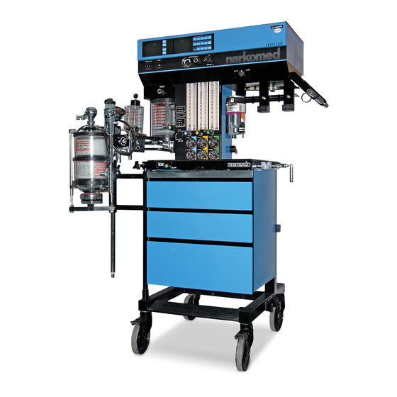
RETURN TO THIS MANUAL'S TABLE OF CONTENTS RETURN TO CD-ROM TABLE OF CONTENTS NM2B CONTENTS (continued) DESCRIPTION PAGE 6.24 Manual Sphygmomanometer ....... . 6-39 6.24A Bellows: Adult . - Page 6 RETURN TO THIS MANUAL'S TABLE OF CONTENTS RETURN TO CD-ROM TABLE OF CONTENTS NARKOMED 2B ANESTHESIA SYSTEM SYSTEM ALARM BOOM CONTROL DISPLAY KEYS DATA DISPLAY MONITOR CONTROL KEYS MANUAL SPHYGMOMANOMETER (OPTIONAL) BREATHING SYSTEM SENSOR INTERFACE PANEL SV20001 Rev. F...
-
Page 7: Introduction
The PMS PROCEDURE in Section 6 must also be performed after any component has been replaced. The general arrangement of the Narkomed 2B Anesthesia System is shown on the opposite page. WARNINGS are used in this manual before procedures which if not performed correctly could result in personal injury. - Page 8 RETURN TO THIS MANUAL'S TABLE OF CONTENTS RETURN TO CD-ROM TABLE OF CONTENTS INTRODUCTION NM2B Copyright Copyright © 2001 by Draeger Medical, Inc. All rights reserved. No part of this publication may be reproduced, transmitted, transcribed, or stored in a retrieval system in any form or by any means, electronic or mechanical, including photocopying and recording, without the written permission of Draeger Medical, Inc.
- Page 9 DIAGNOSTICS 2.0 DIAGNOSTICS The Narkomed 2B contains a diagnostic system that monitors certain system functions and records their operational status. A series of tests is performed when the system is powered up and the results are displayed on the diagnostics screen shown in Figure 2-1. Further diagnostic functions are available through service screens that can be called up by a TSR at the display panel.
-
Page 10: Service Menu Screen
RETURN TO THIS MANUAL'S TABLE OF CONTENTS RETURN TO CD-ROM TABLE OF CONTENTS DIAGNOSTICS (continued) NM2B Service Menu Screen To access the Service Menu Screen, press and hold the CONFIG key, and (while holding the CONFIG key) simultaneously press the 21% and APNEA ALARM DISABLE keys. - Page 11 RETURN TO THIS MANUAL'S TABLE OF CONTENTS RETURN TO CD-ROM TABLE OF CONTENTS NM2B DIAGNOSTICS (continued) 2.1.1 Diagnostics Menu Screen Pressing the DIAGNOSTICS key on the Service Menu Screen brings up the Diagnostics Menu Screen. Figure 2-3 shows a typical Diagnostics menu which displays the last service date and an error log.
- Page 12 RETURN TO THIS MANUAL'S TABLE OF CONTENTS RETURN TO CD-ROM TABLE OF CONTENTS DIAGNOSTICS (continued) NM2B Table 2-1: NARKOMED 2B ERROR CODES, GROUP 1 Left Right Char. Error(s) Char. Error(s) No Error No Error System memory fail (checkerboard test) CRT controller fail (readback test)
- Page 13 RETURN TO THIS MANUAL'S TABLE OF CONTENTS RETURN TO CD-ROM TABLE OF CONTENTS NM2B DIAGNOSTICS (continued) Table 2-2: NARKOMED 2B ERROR CODES, GROUP 2 Left Right Char. Error(s) Char. Error(s) No Error No Error Backup audio fail (sound generation test) A/D conv.
- Page 14 RETURN TO THIS MANUAL'S TABLE OF CONTENTS RETURN TO CD-ROM TABLE OF CONTENTS DIAGNOSTICS (continued) NM2B Table 2-3: NARKOMED 2B ERROR CODES, GROUP 3 Left Right Char. Error(s) Char. Error(s) No Error No Error Backup memory fail (ROM compare test)
- Page 15 Troubleshooting should begin with a check of the power supply voltages on the processor board (see Section 3) followed by a check of all connections to the processor assembly. Refer to Section 4 for removal and replacement procedures for the field-replaceable assemblies in the NARKOMED 2B. Rev. L 2-5B...
- Page 16 RETURN TO THIS MANUAL'S TABLE OF CONTENTS RETURN TO CD-ROM TABLE OF CONTENTS DIAGNOSTICS (continued) NM2B 2.1.1.1 Key Panel Test Screen Pressing the KEY TEST key in the Diagnostics Menu Screen allows the TSR to check each key on the display panel.
- Page 17 RETURN TO THIS MANUAL'S TABLE OF CONTENTS RETURN TO CD-ROM TABLE OF CONTENTS NM2B DIAGNOSTICS (continued) 2.1.2 Calibration Menu Screen Pressing the CALIBRATION key on the Service Menu Screen brings up the Calibration Menu Screen. This menu allows the TSR to perform calibration for the Oxygen Analyzer sensor and the Breathing Pressure Monitor.
- Page 18 RETURN TO THIS MANUAL'S TABLE OF CONTENTS RETURN TO CD-ROM TABLE OF CONTENTS...
-
Page 19: Troubleshooting
Power Supply and Voltage Distribution In the NARKOMED 2B the power supply outputs at J10 are connected to J5 on the processor board for distribution. The CRTs are powered by 12 VDC; the ventilator controller and the alarm channel are powered by 8 VDC. The processor is powered by 5 VDC along with the other voltages. - Page 20 RETURN TO THIS MANUAL'S TABLE OF CONTENTS RETURN TO CD-ROM TABLE OF CONTENTS TROUBLESHOOTING GUIDE (continued) NM2B TOP VIEW OF PROCESSOR ASSEMBLY SV20313 Figure 3-1: PROCESSOR BOARD VOLTAGE TEST POINTS Rev. A...
-
Page 21: Battery
Troubleshooting Guides Table 3-2 lists common failure modes and symptoms (excluding simultaneous multiple faults) for the monitoring and display devices in the NARKOMED 2B. Each failure mode or symptom is keyed to a troubleshooting guide flow chart on the following pages to assist in locating a problem. These flow charts assume that the machine is plugged into an AC outlet with the correct voltage, and the machine is not running on its backup battery. - Page 22 RETURN TO THIS MANUAL'S TABLE OF CONTENTS RETURN TO CD-ROM TABLE OF CONTENTS TROUBLESHOOTING GUIDE (continued) NM2B GUIDE 1: Loss of O Monitor START OXYGEN ANALYZER FUNCTIONAL? CONNECT OXYGEN "O2 SENS DISC" SENSOR CABLE TO DISPLAYED ON INTERFACE PANEL CENTRALERT ALARM DISPLAY? PERFORM A COMPLETE PMS...
- Page 23 RETURN TO THIS MANUAL'S TABLE OF CONTENTS RETURN TO CD-ROM TABLE OF CONTENTS NM2B TROUBLESHOOTING GUIDE (continued) GUIDE 2: Loss of Breathing Pressure Monitor START BREATHING PRESSURE MONITOR FUNCTIONAL? PERFORM A BREATHING COMPLETE PMS PRESSURE MONITOR ON UNIT PILOT LINE FUNCTIONAL? CONNECT CONNECTED TO...
- Page 24 RETURN TO THIS MANUAL'S TABLE OF CONTENTS RETURN TO CD-ROM TABLE OF CONTENTS TROUBLESHOOTING GUIDE (continued) NM2B GUIDE 3: Loss of Respiratory Volume Monitor START VOLUME MONITOR FUNCTIONAL? CONNECT VOLUME "VOL SENS DISC" SENSOR CABLE TO DISPLAYED ON INTERFACE PANEL CENTRALERT ALARM DISPLAY? PERFORM A...
- Page 25 RETURN TO THIS MANUAL'S TABLE OF CONTENTS RETURN TO CD-ROM TABLE OF CONTENTS NM2B TROUBLESHOOTING GUIDE (continued) GUIDE 4: No Audio Alarms START WARNINGS AND CAUTIONS AUDIBLY ANNUNCIATED? REPLACE PROCESSOR ASSEMBLY AS OUTLINED IN PROCEDURE 4.26 PERFORM A WARNINGS AND COMPLETE PMS CAUTIONS AUDIBLY ON UNIT...
- Page 26 RETURN TO THIS MANUAL'S TABLE OF CONTENTS RETURN TO CD-ROM TABLE OF CONTENTS TROUBLESHOOTING GUIDE (continued) NM2B GUIDE 5: Vitalink Failure START DOES HOST FAIL TO COMMUNICATE WITH PERIPHERAL DEVICE? CONNECT PERIPHERAL PERIPHERAL CABLE CABLE CONNECTED TO SERIAL TO SERIAL INTERFACE DOES PORT? PERFORM A...
- Page 27 RETURN TO THIS MANUAL'S TABLE OF CONTENTS RETURN TO CD-ROM TABLE OF CONTENTS NM2B TROUBLESHOOTING GUIDE (continued) GUIDE 6: Incorrect Display START IS WRONG MONITOR SCREEN DISPLAYED? REPLACE PROCESSOR ASSEMBLY AS OUTLINED IN PROCEDURE 4.26 IS WRONG PERFORM A MONITOR SCREEN COMPLETE PMS DISPLAYED? ON UNIT...
- Page 28 RETURN TO THIS MANUAL'S TABLE OF CONTENTS RETURN TO CD-ROM TABLE OF CONTENTS TROUBLESHOOTING GUIDE (continued) NM2B GUIDE 7: No Oxygen Ratio Monitor Alarms START ARE O2 / N2O RATIO ALARMS FUNCTIONAL? IS O2 / N2O "O2 / N20 LOW" IS O2 / N2O PERFORM A FLOW RATIO...
- Page 29 RETURN TO THIS MANUAL'S TABLE OF CONTENTS RETURN TO CD-ROM TABLE OF CONTENTS NM2B TROUBLESHOOTING GUIDE (continued) GUIDE 8: No Oxygen Supply Pressure Alarms START OXYGEN SUPPLY PRESSURE ALARMS FUNCTIONAL? IS O2 "LOW O2 SUPPLY" IS O2 PERFORM A SUPPLY PRESSURE DISPLAYED ON SUPPLY PRESSURE COMPLETE PMS...
- Page 30 RETURN TO THIS MANUAL'S TABLE OF CONTENTS RETURN TO CD-ROM TABLE OF CONTENTS TROUBLESHOOTING GUIDE (continued) NM2B GUIDE 9: Display Screens Blank Upon System Power-Up START DISPLAY SCREENS BLANK UPON SYSTEM POWER-UP? PERFORM A DISPLAY SCREENS CONNECT COMPLETE PMS CABLES BLANK UPON SYSTEM CABLES ON UNIT...
- Page 31 RETURN TO THIS MANUAL'S TABLE OF CONTENTS RETURN TO CD-ROM TABLE OF CONTENTS NM2B TROUBLESHOOTING GUIDE (continued) GUIDE 10: No Keypanel Response START DISPLAY PANEL KEYS WORKING PROPERLY? PERFORM A DISPLAY PANEL COMPLETE PMS CONNECT CABLES CABLES KEYS WORKING ON UNIT TO J1 &...
- Page 32 RETURN TO THIS MANUAL'S TABLE OF CONTENTS RETURN TO CD-ROM TABLE OF CONTENTS...
-
Page 33: Replacement Procedures
REPLACEMENT PROCEDURES REPLACEMENT PROCEDURES This section outlines removal and replacement procedures for the field-replaceable assemblies of the NARKOMED 2B Anesthesia System. These procedures are to be performed only by a Draeger Medical, Inc. qualified Technical Service Representative (TSR). The following are the only procedures authorized by Draeger Medical, Inc. to be performed in the field. -
Page 34: Cylinder Yoke Assemblies
RETURN TO THIS MANUAL'S TABLE OF CONTENTS RETURN TO CD-ROM TABLE OF CONTENTS REPLACEMENT PROCEDURES (continued) NM2B Cylinder Yoke Assemblies Each cylinder yoke contains a replaceable filter and check valve assembly. Replacement of this assembly requires that the yoke be removed from the anesthesia machine. - Page 35 RETURN TO THIS MANUAL'S TABLE OF CONTENTS RETURN TO CD-ROM TABLE OF CONTENTS NM2B REPLACEMENT PROCEDURES (continued) YOKE ASSEMBLY (TYPICAL) YOKE SPACER FILTER AND CHECK VALVE ASSEMBLY SV40601 GAS LINE Figure 4-1: CYLINDER YOKE ASSEMBLY Rev. J...
- Page 36 RETURN TO THIS MANUAL'S TABLE OF CONTENTS RETURN TO CD-ROM TABLE OF CONTENTS REPLACEMENT PROCEDURES (continued) NM2B 4.1.12 Position the yoke on the spacer, and install the two mounting screws and lockwashers. Tighten the screws securely. Connect the gas line fitting to the yoke.
-
Page 37: Cylinder Pressure Regulators
RETURN TO THIS MANUAL'S TABLE OF CONTENTS RETURN TO CD-ROM TABLE OF CONTENTS NM2B REPLACEMENT PROCEDURES (continued) Cylinder Pressure Regulators Access to the cylinder pressure regulators requires that the table top be removed from the anesthesia machine. Figure 4-2 shows the mounting arrangement of the regulators and typical connections. - Page 38 RETURN TO THIS MANUAL'S TABLE OF CONTENTS RETURN TO CD-ROM TABLE OF CONTENTS REPLACEMENT PROCEDURES (continued) NM2B TOP VIEW OF NARKOMED 4 WITH TABLE TOP REMOVED O CYLINDER N O CYLINDER PRESSURE PRESSURE REGULATOR REGULATOR SCREWS AIR OR OPTIONAL 3RD GAS CYLINDER PRESSURE REGULATOR TEST GAUGE CONNECTION...
- Page 39 RETURN TO THIS MANUAL'S TABLE OF CONTENTS RETURN TO CD-ROM TABLE OF CONTENTS NM2B REPLACEMENT PROCEDURES (continued) 4.2.14 Tighten the regulator mounting setscrews to a torque of 50 to 55 in. lbs. 4.2.15 Tighten the compression fittings. 4.2.16 Locate the TEE fitting in the ¼ in. diameter regulator output line, and remove the plug from the TEE fitting.
-
Page 40: Cylinder Cutoff Valves (Canada)
RETURN TO THIS MANUAL'S TABLE OF CONTENTS RETURN TO CD-ROM TABLE OF CONTENTS REPLACEMENT PROCEDURES (continued) NM2B Cylinder Cutoff Valves (Canada) Access to the cylinder cutoff valves requires removal of the table top from the anesthesia machine. Figure 4-3 shows the locations of the O , Air or 3rd gas, and N O cutoff valve assemblies. - Page 41 RETURN TO THIS MANUAL'S TABLE OF CONTENTS RETURN TO CD-ROM TABLE OF CONTENTS NM2B REPLACEMENT PROCEDURES (continued) SV50526 O2 CYLINDER AIR OR 3RD GAS N2O CYLINDER CUTOFF VALVE CYLINDER CUTOFF VALVE ASSEMBLY CUTOFF VALVE ASSEMBLY ASSEMBLY Figure 4-3: CYLINDER CUTOFF VALVES (CANADA) Rev.
- Page 42 RETURN TO THIS MANUAL'S TABLE OF CONTENTS RETURN TO CD-ROM TABLE OF CONTENTS REPLACEMENT PROCEDURES (continued) NM2B 4.3.13 Connect and tighten the compression fittings at points marked C on the illustration. 4.3.14 Perform the following test: --Remove the plug from the test gauge connection at the Tee fitting in the regulator outlet piping, and install a test gauge.
-
Page 43: Cylinder And Pipeline Pressure Gauges
RETURN TO THIS MANUAL'S TABLE OF CONTENTS RETURN TO CD-ROM TABLE OF CONTENTS NM2B REPLACEMENT PROCEDURES (continued) Cylinder and Pipeline Pressure Gauges Replacement of the cylinder and pipeline pressure gauges requires that the plexiglass front cover be removed from the gas instrumentation panel, and also the rear cover for access to the gauge connections. - Page 44 RETURN TO THIS MANUAL'S TABLE OF CONTENTS RETURN TO CD-ROM TABLE OF CONTENTS REPLACEMENT PROCEDURES (continued) NM2B REAR VIEW OF FLOWMETER HOUSING WITH REAR COVER REMOVED FRONT COVER RETAINER SCREWS GAUGE MOUNTING NUTS (TYPICAL) FLEXIBLE TUBING CONNECTION (PIPELINE PRESSURE GAUGES) COMPRESSION FITTING SV40644 (CYLINDER PRESSURE GAUGES)
- Page 45 RETURN TO THIS MANUAL'S TABLE OF CONTENTS RETURN TO CD-ROM TABLE OF CONTENTS NM2B REPLACEMENT PROCEDURES (continued) NOTE: Intermediate assemblies may need to be removed to allow access to the gauge connections and mounting hardware. Be sure to keep a record of the disassembly sequence so that all tubing can be correctly re-assembled.
- Page 46 RETURN TO THIS MANUAL'S TABLE OF CONTENTS RETURN TO CD-ROM TABLE OF CONTENTS REPLACEMENT PROCEDURES (continued) NM2B 4.4.14.1 Open the cylinder valve and check for a pressure indication on the corresponding gauge at the gas instrumentation panel. NOTE: The cylinder used for this test must contain the following minimum pressure: : 1000 PSI : 700 PSI...
-
Page 47: Flowmeters
RETURN TO THIS MANUAL'S TABLE OF CONTENTS RETURN TO CD-ROM TABLE OF CONTENTS NM2B REPLACEMENT PROCEDURES (continued) Flowmeters The flowmeter tubes are held by compression in gaskets at the top and bottom of each tube. Each upper gasket is seated in an adjustable retainer that allows removal of the tube as shown in Figure 4-5. - Page 48 RETURN TO THIS MANUAL'S TABLE OF CONTENTS RETURN TO CD-ROM TABLE OF CONTENTS REPLACEMENT PROCEDURES (continued) NM2B FLOW TUBE RETAINER SCREW UPPER FLOW TUBE RETAINER FLOW TUBE LIGHTING CHANNEL FLOW RESTRICTOR SV40605 GUIDE RING GASKET Figure 4-5: FLOWMETERS Rev. J 4-16...
- Page 49 RETURN TO THIS MANUAL'S TABLE OF CONTENTS RETURN TO CD-ROM TABLE OF CONTENTS NM2B REPLACEMENT PROCEDURES (continued) 4.5.13 Loosen the screw directly above the flowmeter tube to be replaced. Turning the screw counter clockwise will raise the upper flow tube retainer.
- Page 50 RETURN TO THIS MANUAL'S TABLE OF CONTENTS RETURN TO CD-ROM TABLE OF CONTENTS REPLACEMENT PROCEDURES (continued) NM2B 4.5.20 Place the plexiglass cover over the gauges and flow tubes, and reinstall the cover screws. Do not over-tighten these screws as the plexiglass may crack.
-
Page 51: Flow Control Valves
RETURN TO THIS MANUAL'S TABLE OF CONTENTS RETURN TO CD-ROM TABLE OF CONTENTS NM2B REPLACEMENT PROCEDURES (continued) Flow Control Valves The flow control valves have replaceable elements that are removable from the front of the gas instrumentation panel as shown in Figure 4-6. Each flow control knob has a clockwise positive stop arrangement that prevents damage to the valve seat. - Page 52 RETURN TO THIS MANUAL'S TABLE OF CONTENTS RETURN TO CD-ROM TABLE OF CONTENTS REPLACEMENT PROCEDURES (continued) NM2B VALVE FLOW CONTROL HOUSING VALVE STOP PIN WRENCH FLATS KNOB GUARD (NEW STYLE) LABEL KNOB KNOB GUARD (OLD STYLE) SV20606 Figure 4-6: FLOW CONTROL VALVES Rev.
- Page 53 RETURN TO THIS MANUAL'S TABLE OF CONTENTS RETURN TO CD-ROM TABLE OF CONTENTS NM2B REPLACEMENT PROCEDURES (continued) 4.6.14 Set the System Power switch to ON. 4.6.15A For the O flow control valve: Open the oxygen cylinder valve. Turn the flow control valve clockwise until the flow rate will not drop any further.
-
Page 54: Oxygen Supply Pressure Failure Protection Device
RETURN TO THIS MANUAL'S TABLE OF CONTENTS RETURN TO CD-ROM TABLE OF CONTENTS REPLACEMENT PROCEDURES (continued) NM2B Oxygen Supply Pressure Failure Protection Device The oxygen supply failure protection devices (failsafe assemblies) are located behind the gas instrumentation panel. Access to these assemblies requires removal of the rear cover. - Page 55 RETURN TO THIS MANUAL'S TABLE OF CONTENTS RETURN TO CD-ROM TABLE OF CONTENTS NM2B REPLACEMENT PROCEDURES (continued) EARLIER DESIGN SUPPLIED LATER DESIGN OF MACHINES WITH FITTINGS WITH FLOWMETER ASSEMBLIES HAVING AN ORC O2 CONTROL LINE CONNECTION OXYGEN SUPPLY FAILURE PROTECTION DEVICE (N2O CONTROL DEVICE ILLUSTRATED) OUTLET...
- Page 56 RETURN TO THIS MANUAL'S TABLE OF CONTENTS RETURN TO CD-ROM TABLE OF CONTENTS REPLACEMENT PROCEDURES (continued) NM2B 4.7.12 Perform the following test: 4.7.12.1 Open the cylinder valves. 4.7.12.2 Set the System Power switch to ON. 4.7.12.3 Set the oxygen flow to five liters per minute. 4.7.12.4 Set the other gas flow to five liters per minute.
-
Page 57: Oxygen Supply Pressure Alarm Switch (Earlier Machines)
RETURN TO THIS MANUAL'S TABLE OF CONTENTS RETURN TO CD-ROM TABLE OF CONTENTS NM2B REPLACEMENT PROCEDURES (continued) Oxygen Supply Pressure Alarm Switch (earlier machines) The oxygen supply pressure alarm switch is located behind the gas instrumentation panel. Access to the switch requires removal of the flowmeter housing rear cover. - Page 58 RETURN TO THIS MANUAL'S TABLE OF CONTENTS RETURN TO CD-ROM TABLE OF CONTENTS REPLACEMENT PROCEDURES (continued) NM2B REAR VIEW, FLOWMETER HOUSING WITH REAR COVER REMOVED O LINES ALARM WIRES INCREASE SETPOINT ADJUSTMENT OXYGEN SUPPLY WHEEL PRESSURE ALARM SWITCH OSPAS Figure 4-8: OXYGEN SUPPLY PRESSURE ALARM SWITCH Rev.
- Page 59 RETURN TO THIS MANUAL'S TABLE OF CONTENTS RETURN TO CD-ROM TABLE OF CONTENTS NM2B REPLACEMENT PROCEDURES (continued) 4.8.15 Open the oxygen cylinder valve and set the System Power switch to 4.8.16 Set the oxygen flow to five liters per minute. 4.8.17 Close the oxygen cylinder valve.
-
Page 60: Oxygen Supply Pressure Alarm Whistle (Canada)
RETURN TO THIS MANUAL'S TABLE OF CONTENTS RETURN TO CD-ROM TABLE OF CONTENTS REPLACEMENT PROCEDURES (continued) NM2B Oxygen Supply Pressure Alarm Whistle (Canada) The oxygen supply pressure alarm whistle is located inside the flowmeter housing. Access to the whistle assembly requires removal of the flowmeter housing rear cover. - Page 61 RETURN TO THIS MANUAL'S TABLE OF CONTENTS RETURN TO CD-ROM TABLE OF CONTENTS NM2B REPLACEMENT PROCEDURES (continued) REAR VIEW OF FLOWMETER HOUSING (CANADA) WITH COVER REMOVED COMPRESSION FITTING WHISTLE ASSEMBLY COMPRESSION FITTING COMPRESSION FITTING SIDE VIEW OF LOWER COMPRESSION FITTING SV20324 Figure 4-9: OXYGEN SUPPLY PRESSURE ALARM WHISTLE (CANADA) Rev.
-
Page 62: Oxygen Ratio Monitor/Controller
RETURN TO THIS MANUAL'S TABLE OF CONTENTS RETURN TO CD-ROM TABLE OF CONTENTS REPLACEMENT PROCEDURES (continued) NM2B 4.10 Oxygen Ratio Monitor/Controller The oxygen ratio monitor/controller (ORMC) is located in the vapor box and is accessible by removing the rear cover panel above the vaporizer mounts. Figure 4-10 shows the location of the ORMC mounting screws and connections. - Page 63 RETURN TO THIS MANUAL'S TABLE OF CONTENTS RETURN TO CD-ROM TABLE OF CONTENTS NM2B REPLACEMENT PROCEDURES (continued) NARKOMED 4 REAR VIEW O TUBING TUBING MPL SWITCH ADJUSTMENT (TURN CLOCKWISE TO DECREASE SETPOINT) OXYGEN RATIO MOUNTING MONITOR/CONTROLLER BRACKET SWITCH MOUNT SWITCH ADJUSTMENT CAM (TURN CLOCKWISE TO CLOSE CONTACTS) SV40311...
- Page 64 RETURN TO THIS MANUAL'S TABLE OF CONTENTS RETURN TO CD-ROM TABLE OF CONTENTS REPLACEMENT PROCEDURES (continued) NM2B 4.10.14 Connect the flexible N O tubing that was removed in the previous step to the tee fitting at the front of the replacement ORMC, and secure the connection with a new tie strap clamp.
- Page 65 RETURN TO THIS MANUAL'S TABLE OF CONTENTS RETURN TO CD-ROM TABLE OF CONTENTS NM2B REPLACEMENT PROCEDURES (continued) 4.10.19.9 The yellow O O FLOW RATIO lamp on the alarm panel should be lighted. 4.10.19.10 Close the oxygen flow control valve. The nitrous oxide flow should decrease proportionally, and the oxygen concentration should remain between 21% and 29% oxygen.
- Page 66 RETURN TO THIS MANUAL'S TABLE OF CONTENTS RETURN TO CD-ROM TABLE OF CONTENTS REPLACEMENT PROCEDURES (continued) NM2B 4.11 Oxygen Ratio Controller (machines with E-Z Plumb piping) The Oxygen Ratio Controller (ORC) is part of the N O flowmeter sub-assembly and is located within the flowmeter housing. The ORC is accessible by removing the rear flowmeter housing cover.
- Page 67 RETURN TO THIS MANUAL'S TABLE OF CONTENTS RETURN TO CD-ROM TABLE OF CONTENTS NM2B REPLACEMENT PROCEDURES (continued) REAR VIEW OF FLOWMETER HOUSING SV50504 WITH REAR COVER REMOVED ADJUSTING SCREW LOCKNUT CONNECTION ASSEMBLY O-RING, #105 (NEOPRENE) FILTER O-RING, 0.066 X 0.042 (BUNA-N) ASSEMBLY MOUNTING...
- Page 68 RETURN TO THIS MANUAL'S TABLE OF CONTENTS RETURN TO CD-ROM TABLE OF CONTENTS REPLACEMENT PROCEDURES (continued) NM2B 4.11.12 Perform the ORC adjustment procedure given in Section 5 of this manual. NOTE: There are two adjustment procedures - one for ORC P/N 4111800, and one for low flow ORC P/N 4113229.
-
Page 69: Vaporizers
RETURN TO THIS MANUAL'S TABLE OF CONTENTS RETURN TO CD-ROM TABLE OF CONTENTS NM2B REPLACEMENT PROCEDURES (continued) 4.12 Vaporizers Each vaporizer is held to the machine by two metric sized hex screws. These screws are accessible at the back of the vaporizer mount, below the interlock mechanism as shown in Figure 4-12. - Page 70 RETURN TO THIS MANUAL'S TABLE OF CONTENTS RETURN TO CD-ROM TABLE OF CONTENTS REPLACEMENT PROCEDURES (continued) NM2B VAPORIZER MOUNT LOCKING INTERLOCK HANDWHEEL SETSCREW VAPORIZER VAPORIZER MOUNTING SCREWS (2 EA) (RECESSED) SV20325 VAPORIZER INTERLOCK MECHANISM REAR VIEW LEFT SETSCREW CENTER VAPORIZER SETSCREWS RIGHT MOUNTING SCREW...
- Page 71 RETURN TO THIS MANUAL'S TABLE OF CONTENTS RETURN TO CD-ROM TABLE OF CONTENTS NM2B REPLACEMENT PROCEDURES (continued) NOTE: Should a vaporizer containing anesthetic agent be accidentally tilted more than 45 degrees, it must be drained and flushed in accordance with instructions given in the manual supplied with the vaporizer.
-
Page 72: O Flush Valve
RETURN TO THIS MANUAL'S TABLE OF CONTENTS RETURN TO CD-ROM TABLE OF CONTENTS REPLACEMENT PROCEDURES (continued) NM2B 4.13 O2 Flush Valve The O flush valve is located at the front of the machine next to the freshgas outlet. Access to the flush valve requires removal of the table top. Figure 4-13 shows the mounting and assembly details of the flush valve. - Page 73 RETURN TO THIS MANUAL'S TABLE OF CONTENTS RETURN TO CD-ROM TABLE OF CONTENTS NM2B REPLACEMENT PROCEDURES (continued) COMPRESSION FITTINGS RESTRICTOR FLUSH VALVE SPACER ACCESS HOLES WASHER INTERNAL TOOTH LOCKWASHER PUSH BUTTON GUARD RING FRONT VIEW WITH TABLE TOP REMOVED SET SCREWS SV49099 Figure 4-13: O FLUSH VALVE...
- Page 74 RETURN TO THIS MANUAL'S TABLE OF CONTENTS RETURN TO CD-ROM TABLE OF CONTENTS REPLACEMENT PROCEDURES (continued) NM2B 4.13.12 Connect the compression fittings to the valve. Be sure the flow restrictor is in place at the right-angle fitting. 4.13.13 Place the washer and the O Flush button on the valve shaft.
- Page 75 RETURN TO THIS MANUAL'S TABLE OF CONTENTS RETURN TO CD-ROM TABLE OF CONTENTS NM2B REPLACEMENT PROCEDURES (continued) 4.13.16 Connect the absorber freshgas hose to the freshgas outlet. 4.13.17 Replace the table top and secure it with the mounting screws. 4.13.18 Connect the pipeline hoses. 4.13.19 Perform the PMS Procedure given in Section 6.
-
Page 76: Av-E Ventilator Controller Assembly
RETURN TO THIS MANUAL'S TABLE OF CONTENTS RETURN TO CD-ROM TABLE OF CONTENTS REPLACEMENT PROCEDURES (continued) NM2B 4.14 AV-E Ventilator Controller Assembly The ventilator controller assembly is located in the left side of the ventilator box. Access to the controller requires removing the front panel from the ventilator box. - Page 77 RETURN TO THIS MANUAL'S TABLE OF CONTENTS RETURN TO CD-ROM TABLE OF CONTENTS NM2B REPLACEMENT PROCEDURES (continued) VENTILATOR BOX TOP VIEW SV20327 IN-LINE CONNECTOR VENTILATOR SWITCH VENTILATOR CONTROLLER ASSEMBLY VENTILATOR VENTILATOR BOX VENTILATOR BOX CONTROLLER ASSEMBLY FRONT PANEL FRONT PANEL MOUNTING SCREWS SCREWS (6) Figure 4-14: VENTILATOR CONTROLLER ASSEMBLY...
- Page 78 RETURN TO THIS MANUAL'S TABLE OF CONTENTS RETURN TO CD-ROM TABLE OF CONTENTS REPLACEMENT PROCEDURES (continued) NM2B 4.14.6 Mount the replacement controller assembly to the floor of the ventilator box and secure it with the two mounting screws. 4.14.7 Join the ventilator switch in-line connector, and replace the front panel of the ventilator box.
-
Page 79: Av-E Ventilator Solenoid Valve
RETURN TO THIS MANUAL'S TABLE OF CONTENTS RETURN TO CD-ROM TABLE OF CONTENTS NM2B REPLACEMENT PROCEDURES (continued) 4.15 AV-E Ventilator Solenoid Valve The ventilator solenoid valve is located in the ventilator box and is mounted on the inner back wall of the box. Replacement of the solenoid valve requires lifting the monitor box to gain access to its mounting and connections. - Page 80 RETURN TO THIS MANUAL'S TABLE OF CONTENTS RETURN TO CD-ROM TABLE OF CONTENTS REPLACEMENT PROCEDURES (continued) NM2B VENTILATOR BOX TOP VIEW COVER SCREWS VENTILATOR SOLENOID VALVE AC POWER MOUNTING SCREWS (2) FILTER COVER INPUT PORT OUTPUT PORT SV20328 VENTILATOR SOLENOID VALVE Figure 4-15: VENTILATOR SOLENOID VALVE Rev.
- Page 81 RETURN TO THIS MANUAL'S TABLE OF CONTENTS RETURN TO CD-ROM TABLE OF CONTENTS NM2B REPLACEMENT PROCEDURES (continued) 4.15.6 Remove the prop from the rear left side of the monitor box, and return the box to its normal position. 4.15.7 Raise the front of the monitor box approximately four inches, and prop the box open.
-
Page 82: Av-2 Ventilator Controller Assembly
RETURN TO THIS MANUAL'S TABLE OF CONTENTS RETURN TO CD-ROM TABLE OF CONTENTS REPLACEMENT PROCEDURES (continued) NM2B 4.16 AV-2 Ventilator Controller Assembly The Ventilator Controller assembly is attached to the left front panel of the ventilator box and includes electrical and pneumatic components. Figure 4-16 shows the mounting screw locations and connections to the ventilator controller. - Page 83 RETURN TO THIS MANUAL'S TABLE OF CONTENTS RETURN TO CD-ROM TABLE OF CONTENTS NM2B REPLACEMENT PROCEDURES (continued) TO VENTURI TO AUTO- RANGING VALVE O2 SUPPLY TO VENT TOP VIEW OF CONTROLLER ASSEMBLY IN VENTILATOR RETAINING SCREWS (2X) SUPPLY VALVE INSPIRATORY SOLENOID FLOW REGULATOR...
- Page 84 RETURN TO THIS MANUAL'S TABLE OF CONTENTS RETURN TO CD-ROM TABLE OF CONTENTS REPLACEMENT PROCEDURES (continued) NM2B 4.16.10 Slide the controller into the ventilator box, carefully fit the locking tab into its receptacle at the right side of the panel, and slide the assembly to the right until it is properly seated.
-
Page 85: Convenience Outlet Ac Power Filter
RETURN TO THIS MANUAL'S TABLE OF CONTENTS RETURN TO CD-ROM TABLE OF CONTENTS NM2B REPLACEMENT PROCEDURES (continued) 4.17 Convenience Outlet AC Power Filter The convenience outlet AC power filter is located in the back of the ventilator box near the AC convenience outlets. Access to the power filter requires lifting the monitor box. - Page 86 RETURN TO THIS MANUAL'S TABLE OF CONTENTS RETURN TO CD-ROM TABLE OF CONTENTS REPLACEMENT PROCEDURES (continued) NM2B VENTILATOR BOX TOP VIEW FILTER CONVENIENCE OUTLET AC MOUNTING POWER FILTER SPACERS (2X) BROWN BLACK GREEN/YELLOW BLUE WHITE COVER SCREWS AC POWER FILTER COVER SV20331 Figure 4-17: CONVENIENCE OUTLET AC POWER FILTER Rev.
- Page 87 RETURN TO THIS MANUAL'S TABLE OF CONTENTS RETURN TO CD-ROM TABLE OF CONTENTS NM2B REPLACEMENT PROCEDURES (continued) 4.17.6 Unscrew the two hex post nuts holding the filter to the ventilator box, and remove the filter. 4.17.7 Install the replacement filter and secure it with the two hex post nuts.
-
Page 88: Av-E Inspiratory Flow Regulator
RETURN TO THIS MANUAL'S TABLE OF CONTENTS RETURN TO CD-ROM TABLE OF CONTENTS REPLACEMENT PROCEDURES (continued) NM2B 4.18 AV-E Inspiratory Flow Regulator The inspiratory flow regulator is located in the ventilator box. Access to the regulator requires removal of the ventilator box front panel, and lifting the monitor box. - Page 89 RETURN TO THIS MANUAL'S TABLE OF CONTENTS RETURN TO CD-ROM TABLE OF CONTENTS NM2B REPLACEMENT PROCEDURES (continued) VENTILATOR BOX TOP VIEW HOSE BARB FITTING COMPRESSION FITTING COMPRESSION FITTING INSPIRATORY FLOW REGULATOR REGULATOR MOUNTING NUT VENTILATOR BOX FRONT PANEL SV20341 SCREWS (4) Figure 4-18: INSPIRATORY FLOW REGULATOR Rev.
- Page 90 RETURN TO THIS MANUAL'S TABLE OF CONTENTS RETURN TO CD-ROM TABLE OF CONTENTS REPLACEMENT PROCEDURES (continued) NM2B 4.18.13 Join the ventilator switch in-line connector, and replace the front panel of the ventilator box. 4.18.14 Perform the PMS Procedure given in Section 6. 4-58...
-
Page 91: Ventilator Bellows Valve And Guide Assembly (Av-E Ventilator)
RETURN TO THIS MANUAL'S TABLE OF CONTENTS RETURN TO CD-ROM TABLE OF CONTENTS NM2B REPLACEMENT PROCEDURES (continued) 4.19 Ventilator Bellows Valve and Guide Assembly (AV-E Ventilator) The ventilator bellows valve and guide assembly is located in the bellows box on the left side of the machine. Access to the valve case and guide assembly requires that the bellows box front panel and the bellows canister be removed from the bellows box. - Page 92 RETURN TO THIS MANUAL'S TABLE OF CONTENTS RETURN TO CD-ROM TABLE OF CONTENTS REPLACEMENT PROCEDURES (continued) NM2B VENTILATOR BOX INSIDE TOP VIEW COMPRESSION FITTING COPPER TUBE VENTILATOR BOX AND BELLOWS BOX FRONT VIEW FRONT PANEL MOUNTINGSCREWS (4X) FRONT PANEL AND TIDAL BELLOWS VOLUME ADJUSTMENT KNOB ASSEMBLY...
- Page 93 RETURN TO THIS MANUAL'S TABLE OF CONTENTS RETURN TO CD-ROM TABLE OF CONTENTS NM2B REPLACEMENT PROCEDURES (continued) BELLOWS BOX FRONT VIEW WITH PANEL REMOVED TIE STRAP EXHAUST COPPER TUBE MINIATURE ACTUATOR INTAKE VALVE CASE ASSEMBLY TIE STRAP VALVE CASE ASSEMBLY SV20312 MOUNTING SCREWS (4X) Figure 4-19: TWO-PIECE TIDAL VOLUME ADJ.
- Page 94 RETURN TO THIS MANUAL'S TABLE OF CONTENTS RETURN TO CD-ROM TABLE OF CONTENTS REPLACEMENT PROCEDURES (continued) NM2B 4.19.10 Carefully cut the tie strap and remove the other end of the large hose at the top of the muffler interface wall. 4.19.11 Remove the three socket head screws securing the bellows top plate to the bellows box.
- Page 95 RETURN TO THIS MANUAL'S TABLE OF CONTENTS RETURN TO CD-ROM TABLE OF CONTENTS NM2B REPLACEMENT PROCEDURES (continued) 4.19.22 Attach the large hose from the muffler interface wall and secure the connection with a new tie strap. 4.19.23 Attach the other large hose to the exhaust port on the valve case assembly and secure the connection with a new tie strap.
- Page 96 RETURN TO THIS MANUAL'S TABLE OF CONTENTS RETURN TO CD-ROM TABLE OF CONTENTS REPLACEMENT PROCEDURES (continued) NM2B Replacement Procedure 2: 4.19.30 Set the System Power switch to STANDBY, remove AC power from the machine, and disable all circuit breakers. 4.19.31 Close all cylinder valves, and disconnect the pipeline hoses from the machine.
- Page 97 RETURN TO THIS MANUAL'S TABLE OF CONTENTS RETURN TO CD-ROM TABLE OF CONTENTS NM2B REPLACEMENT PROCEDURES (continued) VENTILATOR BOX INSIDE TOP VIEW VENTILATOR SOLENOID "OUT" PORT COMPRESSION FITTING COPPER TUBE VENTILATOR BOX AND BELLOWS BOX FRONT VIEW FRONT PANEL MOUNTING SCREWS (4X) BELLOWS GUIDE FRONT PANEL AND TIDAL...
- Page 98 RETURN TO THIS MANUAL'S TABLE OF CONTENTS RETURN TO CD-ROM TABLE OF CONTENTS REPLACEMENT PROCEDURES (continued) NM2B ASSEMBLY WITH ASSEMBLY WITH CLIPPARD VALVE HUMPHREY VALVE BELLOWS BOX INSIDE TOP VIEW INTAKE HOSE EXHAUST HOSE HOSE CLAMP (2X) BELLOWS TOP PLATE MOUNTING SCREWS (3X) COPPER TUBE BELLOWS BOX FRONT VIEW...
- Page 99 RETURN TO THIS MANUAL'S TABLE OF CONTENTS RETURN TO CD-ROM TABLE OF CONTENTS NM2B REPLACEMENT PROCEDURES (continued) 4.19.42 Remove the muffler/silencer (white tube) from the intake flange at the interface wall by turning the muffler counter-clockwise. 4.19.43 Disconnect the press-on clamp and small diameter tubing from the left side hose barb on the ventilator solenoid valve (port labeled "out").
- Page 100 RETURN TO THIS MANUAL'S TABLE OF CONTENTS RETURN TO CD-ROM TABLE OF CONTENTS REPLACEMENT PROCEDURES (continued) NM2B 4.19.53 Connect the copper tube to the tee fitting in the ventilator box. 4.19.54 Install the spacer ring and bellows adjustment rod tube at the top of the valve case and guide assembly.
- Page 101 RETURN TO THIS MANUAL'S TABLE OF CONTENTS RETURN TO CD-ROM TABLE OF CONTENTS NM2B REPLACEMENT PROCEDURES (continued) 4.20 Ventilator Bellows Valve and Guide Assembly with Pressure Limit Control (AV-2 Ventilator) The Ventilator Bellows Valve and Guide Assembly, and the Pressure Limit Control are located in the bellows box on the left side of the machine.
- Page 102 RETURN TO THIS MANUAL'S TABLE OF CONTENTS RETURN TO CD-ROM TABLE OF CONTENTS REPLACEMENT PROCEDURES (continued) NM2B SV50514 1:2 .5 I:E RATIO FREQUENCY /min BELLOWS BOX FRONT VIEW FRONT PANEL BELLOWS MOUNTING SCREWS (4X) GUIDE FRONT PANEL AND KNOB ASSEMBLY CANISTER VOLUME INDICATOR SET SCREWS (2X)
- Page 103 RETURN TO THIS MANUAL'S TABLE OF CONTENTS RETURN TO CD-ROM TABLE OF CONTENTS NM2B REPLACEMENT PROCEDURES (continued) SV50414 BELLOWS BOX FRONT VIEW WITH FRONT PANEL REMOVED FLEX TUBING FROM CONTROLLER UPPER BELLOWS SUPPORT PLATE SUPPORT PLATE BOTTOM VIEW SCREWS (3X) OF BELLOWS BOX PRESSURE LIMIT CONTROL...
- Page 104 RETURN TO THIS MANUAL'S TABLE OF CONTENTS RETURN TO CD-ROM TABLE OF CONTENTS REPLACEMENT PROCEDURES (continued) NM2B NOTE: If components are removed from the support plate, be sure that any spacers and O-rings are correctly positioned during reinstallation. 4.20.14 Following component replacement, position the support plate in the bellows box and reconnect the large and small diameter tubing that was previously removed.
-
Page 105: Alarm Channel (Without Oxygen Supply Pressure Alarm Switch)
RETURN TO THIS MANUAL'S TABLE OF CONTENTS RETURN TO CD-ROM TABLE OF CONTENTS NM2B REPLACEMENT PROCEDURES (continued) 4.21 Alarm Channel (without oxygen supply pressure alarm switch) Replacement of the alarm channel requires removal of the upper flowmeter front cover plate. (On later models the vapor box cover plate is extended to also cover the flowmeter shield and alarm channel.) The alarm channel assembly is held in place by two screws from the back. - Page 106 RETURN TO THIS MANUAL'S TABLE OF CONTENTS RETURN TO CD-ROM TABLE OF CONTENTS REPLACEMENT PROCEDURES (continued) NM2B REAR VIEW FLOWMETER HOUSING WITH REAR COVER REMOVED ALARM P.C. BOARD P.C. BOARD MOUNTING COMPRESSION SCREWS (4) FITTINGS SYSTEM POWER SWITCH FLEXIBLE O CONNECTION ALARM CHANNEL BOTTOM MOUNTING...
- Page 107 RETURN TO THIS MANUAL'S TABLE OF CONTENTS RETURN TO CD-ROM TABLE OF CONTENTS NM2B REPLACEMENT PROCEDURES (continued) 4.21.10 Remove the alarm channel mounting screws. If the machine does not have an auxillary O flow meter, skip the next two steps. 4.21.11 If the machine is equipped with an auxillary O flow meter,pull the alarm channel forward far enough to gain access to the system power...
-
Page 108: Alarm Channel And Oxygen Supply Pressure Alarm Switch
RETURN TO THIS MANUAL'S TABLE OF CONTENTS RETURN TO CD-ROM TABLE OF CONTENTS REPLACEMENT PROCEDURES (continued) NM2B 4.22 Alarm Channel and Oxygen Supply Pressure Alarm Switch The alarm channel assembly includes the oxygen supply pressure alarm switch, the alarm circuit board, and the system power switch. Whenever the alarm channel is replaced, the oxygen supply pressure alarm switch must be tested to ensure that its operating point is set correctly. - Page 109 RETURN TO THIS MANUAL'S TABLE OF CONTENTS RETURN TO CD-ROM TABLE OF CONTENTS NM2B REPLACEMENT PROCEDURES (continued) REAR VIEW SIDE VIEW UPPER ALARM CHANNEL MOUNTING SCREW ALARM CIRCUIT BOARD AUXILARY O2 FLOWMETER CONNECTION O2 CONNECTIONS ADJUSTMENT WHEEL INCREASE SETPOINT OXYGEN DECREASE SETPOINT SUPPLY PRESSURE...
- Page 110 RETURN TO THIS MANUAL'S TABLE OF CONTENTS RETURN TO CD-ROM TABLE OF CONTENTS REPLACEMENT PROCEDURES (continued) NM2B 4.22.15 From the back of the flowmeter housing, remove the upper and lower alarm channel mounting screws. 4.22.16 At the front of the machine, pull the alarm channel assembly forward, and feed the flowmeter lights wire harness through the hole at the top of the alarm channel.
- Page 111 RETURN TO THIS MANUAL'S TABLE OF CONTENTS RETURN TO CD-ROM TABLE OF CONTENTS NM2B REPLACEMENT PROCEDURES (continued) 4.22.32 Open an oxygen cylinder valve and turn the System Power switch to 4.22.33 Set the oxygen flow to five liters per minute. 4.22.34 Close the oxygen cylinder valve.
-
Page 112: Caster
RETURN TO THIS MANUAL'S TABLE OF CONTENTS RETURN TO CD-ROM TABLE OF CONTENTS REPLACEMENT PROCEDURES (continued) NM2B 4.23 Caster Each caster is retained by a set screw in the side of the lower frame rail as shown in Figure 4-23. Caster replacement requires that the machine be tilted to provide enough clearance for the caster stem to be withdrawn from the bottom of the frame rail. - Page 113 RETURN TO THIS MANUAL'S TABLE OF CONTENTS RETURN TO CD-ROM TABLE OF CONTENTS NM2B REPLACEMENT PROCEDURES (continued) 2 TO 3 INCHES SETSCREW PLASTIC SV20334 Figure 4-23: CASTER REPLACEMENT Rev. A 4-81...
- Page 114 RETURN TO THIS MANUAL'S TABLE OF CONTENTS RETURN TO CD-ROM TABLE OF CONTENTS REPLACEMENT PROCEDURES (continued) NM2B 4.23.11 Perform the PMS Procedure given in Section 6, including a vaporizer calibration verification. 4.23.12 Replace any unsecured equipment and accessories that were previously removed.
- Page 115 RETURN TO THIS MANUAL'S TABLE OF CONTENTS RETURN TO CD-ROM TABLE OF CONTENTS NM2B REPLACEMENT PROCEDURES (continued) 4.24 Battery The AC backup battery is located on the power supply assembly in the monitor box and can be replaced without removing the power supply. Access to the battery requires removal of the monitor box top shelf, and removal of the power supply cover plate.
- Page 116 RETURN TO THIS MANUAL'S TABLE OF CONTENTS RETURN TO CD-ROM TABLE OF CONTENTS REPLACEMENT PROCEDURES (continued) NM2B TOP VIEW OF MONITOR BOX GROUND COVER PLATE RETAINER SCREWS (4X) BATTERY WIRE HARNESS CONNECTORS BATTERY RETAINER MOUNTING SCREWS (4X) DISCONNECT AC POWER (J1) AND BATTERY (J7) BATTERY PRIOR TO SERVICING.
- Page 117 RETURN TO THIS MANUAL'S TABLE OF CONTENTS RETURN TO CD-ROM TABLE OF CONTENTS NM2B REPLACEMENT PROCEDURES (continued) 4.24.10 Reinstall the battery retainer and tighten the captive mounting screws. 4.24.11 Reinstall the power supply cover plate. 4.24.12 Connect the cables that were previously removed from J7 and J1 on the power supply assembly.
-
Page 118: Power Supply
RETURN TO THIS MANUAL'S TABLE OF CONTENTS RETURN TO CD-ROM TABLE OF CONTENTS REPLACEMENT PROCEDURES (continued) NM2B 4.25 Power Supply The power supply assembly is located within the monitor box. Access to the power supply requires removal of the monitor box top shelf. Figure 4-25 shows the power supply assembly mounting arrangement and connections. - Page 119 RETURN TO THIS MANUAL'S TABLE OF CONTENTS RETURN TO CD-ROM TABLE OF CONTENTS NM2B REPLACEMENT PROCEDURES (continued) TOP VIEW OF MONITOR BOX CAPTIVE GROUND MOUNTING SCREWS (4X) POWER SUPPLY SV20320 ASSEMBLY Figure 4-25: POWER SUPPLY Rev. A 4-87...
- Page 120 RETURN TO THIS MANUAL'S TABLE OF CONTENTS RETURN TO CD-ROM TABLE OF CONTENTS REPLACEMENT PROCEDURES (continued) NM2B 4.25.11 Place the monitor box top shelf into position, connect its ground wire to the chassis ground tab, and reinstall the top shelf screws. 4.25.12 Reset the circuit breakers at the back of the monitor box.
-
Page 121: Processor Assembly
RETURN TO THIS MANUAL'S TABLE OF CONTENTS RETURN TO CD-ROM TABLE OF CONTENTS NM2B REPLACEMENT PROCEDURES (continued) 4.26 Processor Assembly The processor assembly is located within the monitor box. Access to the processor requires removal of the monitor box top shelf. Figure 4-26 shows the processor assembly mounting arrangement and its connections. - Page 122 RETURN TO THIS MANUAL'S TABLE OF CONTENTS RETURN TO CD-ROM TABLE OF CONTENTS REPLACEMENT PROCEDURES (continued) NM2B TOP VIEW OF MONITOR BOX POWER GROUND SUPPLY ASSEMBLY PROCESSOR ASSEMBLY BAROMED CONNECTION CAPTIVE MOUNTING SCREWS (4X) SV20319 Figure 4-26: PROCESSOR ASSEMBLY Rev. A 4-90...
- Page 123 RETURN TO THIS MANUAL'S TABLE OF CONTENTS RETURN TO CD-ROM TABLE OF CONTENTS NM2B REPLACEMENT PROCEDURES (continued) 4.26.11 Connect the cables that were previously removed from J7 and J1 on the power supply assembly. 4.26.12 Place the monitor box top shelf into position, connect its ground wire to the chassis ground tab, and reinstall the top shelf screws.
-
Page 124: Crt Assemblies
RETURN TO THIS MANUAL'S TABLE OF CONTENTS RETURN TO CD-ROM TABLE OF CONTENTS REPLACEMENT PROCEDURES (continued) NM2B 4.27 CRT Assemblies Access to the two CRT assemblies in the monitor box requires removal of the top shelf. Figure 4-27 shows the CRT mounting arrangement and connections. The following procedure applies to both CRT assemblies. - Page 125 RETURN TO THIS MANUAL'S TABLE OF CONTENTS RETURN TO CD-ROM TABLE OF CONTENTS NM2B REPLACEMENT PROCEDURES (continued) TOP VIEW OF MONITOR BOX CRT ASSEMBLY MOUNTING SCREWS (4X) POWER GROUND SUPPLY ASSEMBLY CRT ASSEMBLIES ON PROCESSOR BOARD SV20317 Figure 4-27: CRT ASSEMBLIES Rev.
- Page 126 RETURN TO THIS MANUAL'S TABLE OF CONTENTS RETURN TO CD-ROM TABLE OF CONTENTS REPLACEMENT PROCEDURES (continued) NM2B VR 402 VERTICAL SIZE CONTRAST VR 100 HORIZONTAL SIZE VR 500 FOCUS VR 401 VERTICAL VR 300 SIZE HORIZONTAL HOLD BRIGHTNESS VR 501 FLYBACK TRANSFORMER Figure 4-27A: CRT ADJUSTMENTS...
- Page 127 RETURN TO THIS MANUAL'S TABLE OF CONTENTS RETURN TO CD-ROM TABLE OF CONTENTS NM2B REPLACEMENT PROCEDURES (continued) WARNING: When making adjustments to the CRT assembly, use only non- metallic alignment tools and be careful not to touch any of the high voltage leads or CRT circuitry.
-
Page 128: Keypads
RETURN TO THIS MANUAL'S TABLE OF CONTENTS RETURN TO CD-ROM TABLE OF CONTENTS REPLACEMENT PROCEDURES (continued) NM2B 4.28 Keypads The alarm keypad and the CRT keypad are part of the front bezel assembly. Access to the keypads requires removal of the monitor box top shelf and removal of the CRT assemblies, processor, and filter panel retainer brackets. - Page 129 RETURN TO THIS MANUAL'S TABLE OF CONTENTS RETURN TO CD-ROM TABLE OF CONTENTS NM2B REPLACEMENT PROCEDURES (continued) REAR VIEW OF BEZEL ASSEMBLY SV20310 RETAINER BRACKET SCREWS (6X) HEX POST (2X) GROUND FILTER PANEL HEX POST RETAINER BRACKET (3X) DETAIL (ROTATED 90 ) GROUND GROUND FILTER PANEL...
- Page 130 RETURN TO THIS MANUAL'S TABLE OF CONTENTS RETURN TO CD-ROM TABLE OF CONTENTS REPLACEMENT PROCEDURES (continued) NM2B 4.28.10 Remove the screws connecting the ground tabs of the keypads to the hex posts on the floor of the monitor box. 4.28.11 Remove the two hex posts from the floor of the monitor box. 4.28.12 Remove the three filter panel retainer brackets from the back of the bezel assembly.
-
Page 131: Spiromed Respiratory Volume Sensor
RETURN TO THIS MANUAL'S TABLE OF CONTENTS RETURN TO CD-ROM TABLE OF CONTENTS NM2B REPLACEMENT PROCEDURES (continued) 4.29 SPIROMED Respiratory Volume Sensor The respiratory volume sensor is installed between the top of the absorber assembly and the expiratory valve. Figure 4-29 shows the volume sensor mounting arrangement, gaskets and connection to the interface panel. - Page 132 RETURN TO THIS MANUAL'S TABLE OF CONTENTS RETURN TO CD-ROM TABLE OF CONTENTS REPLACEMENT PROCEDURES (continued) NM2B EXPIRATORY VALVE VALVE RETAINING NUT RECEPTACLE ON SENSOR GASKET INTERFACE PANEL VOLUME SENSOR SPIROMED SENSOR SENSOR RETAINING SENSOR PLUG GASKET EXPIRATORY VALVE MOUNT ABSORBER ASSEMBLY SV40431...
-
Page 133: Oxygen Sensor
RETURN TO THIS MANUAL'S TABLE OF CONTENTS RETURN TO CD-ROM TABLE OF CONTENTS NM2B REPLACEMENT PROCEDURES (continued) 4.30 Oxygen Sensor The oxygen sensor is located on top of the inspiratory valve. Figure 4-30 shows the arrangement of the sensor capsule and its housing, and also its connection to the interface panel. - Page 134 RETURN TO THIS MANUAL'S TABLE OF CONTENTS RETURN TO CD-ROM TABLE OF CONTENTS REPLACEMENT PROCEDURES (continued) NM2B SV20316 SENSOR HOUSING RECEPTACLE SENSOR CAPSULE ON INTERFACE PANEL SENSOR HOUSING COVER INSPIRATORY VALVE DOME INSPIRATORY SENSOR VALVE DOME CORD PLUG CONNECTOR Figure 4-30: OXYGEN SENSOR REPLACEMENT Rev.
-
Page 135: Manual Sphygmomanometer
RETURN TO THIS MANUAL'S TABLE OF CONTENTS RETURN TO CD-ROM TABLE OF CONTENTS NM2B REPLACEMENT PROCEDURES (continued) 4.31 Manual Sphygmomanometer The manual sphygmomanometer gauge is mounted on a threaded piece attached to the underside of the boom arm mounting block. If the machine is equipped with an optional O.R. - Page 136 RETURN TO THIS MANUAL'S TABLE OF CONTENTS RETURN TO CD-ROM TABLE OF CONTENTS REPLACEMENT PROCEDURES (continued) NM2B INTERFACE PANEL ON LEFT SIDE OF MONITOR BOX BP CUFF BP GUAGE GAUGE MOUNT THREADED MOUNTING RING INTERNAL PIPING CONNECTS BULB FITTING TO GAUGE AND CUFF FITTINGS MANUAL SPHYGMOMANOMETER...
-
Page 137: Auxiliary Oxygen Flowmeter
RETURN TO THIS MANUAL'S TABLE OF CONTENTS RETURN TO CD-ROM TABLE OF CONTENTS NM2B REPLACEMENT PROCEDURES (continued) 4.32 Auxiliary Oxygen Flow Meter Old and new style auxiliary oxygen flowmeters are attached to the side of the machine’s flowmeter housing by two screws - accessible from inside the housing. - Page 138 RETURN TO THIS MANUAL'S TABLE OF CONTENTS RETURN TO CD-ROM TABLE OF CONTENTS REPLACEMENT PROCEDURES (continued) NM2B MOUNTING SCREW (2X) (USED WITH EARLIER MOUNTING ARRANGEMENT) PRESS-ON HOSE CLAMP FLEX TUBING AUXILIARY OXYGEN KEP HEX NUT AUXILIARY O2 FLOWMETER (NEW STYLE ILLUSTRATED) TIE STRAP HOSE BARB FITTING...
-
Page 139: Peep Valve Magnet Assembly Replacement
RETURN TO THIS MANUAL'S TABLE OF CONTENTS RETURN TO CD-ROM TABLE OF CONTENTS NM2B REPLACEMENT PROCEDURES (continued) 4.33 PEEP Valve Magnet Assembly Replacement The PEEP valve magnet assembly removal and replacement is outlined in the following procedure. Figure 4-33 shows the knob and magnet assembly details. NOTE: Some older PEEP valve assemblies require the use of a tamper-proof 5/56 hex key (P/N S010056). - Page 140 RETURN TO THIS MANUAL'S TABLE OF CONTENTS RETURN TO CD-ROM TABLE OF CONTENTS REPLACEMENT PROCEDURES (continued) NM2B O - R I N G M A G N E T A S S E M B L Y O - R I N G R E T A I N I N G R I N G S C R E W S D O W E L P I N...
- Page 141 RETURN TO THIS MANUAL'S TABLE OF CONTENTS RETURN TO CD-ROM TABLE OF CONTENTS NM2B ADJUSTMENT AND CALIBRATION PROCEDURES ADJUSTMENT AND CALIBRATION PROCEDURES Equipment Required: Test Gauges for setting cylinder pressure regulators, Oxygen Monitor for adjusting ORMC or ORC Test fixture with breathing pressure line connector, TEE connector, gauge, and inflation device, for breathing pressure monitor calibration Rev.
- Page 142 RETURN TO THIS MANUAL'S TABLE OF CONTENTS RETURN TO CD-ROM TABLE OF CONTENTS ADJUSTMENT AND CALIBRATION PROCEDURES (continued) NM2B Cylinder Pressure Regulator Adjustment (except CO2) 5.1.1 Disconnect all pipeline hoses and set the System Power switch to ON. 5.1.2 Close all cylinder valves except the O valve.
-
Page 143: Section 5 Adjustment And Calibration Procedures
RETURN TO THIS MANUAL'S TABLE OF CONTENTS RETURN TO CD-ROM TABLE OF CONTENTS NM2B ADJUSTMENT AND CALIBRATION PROCEDURES (continued) CAUTION: Based on information supplied by the cylinder regulator manufacturer, when the regulator is used for gases other than N2O or CO2, its output pressure will decrease 0.5 psi for every 100 psi increase in cylinder pressure above 1000 psi. - Page 144 RETURN TO THIS MANUAL'S TABLE OF CONTENTS RETURN TO CD-ROM TABLE OF CONTENTS ADJUSTMENT AND CALIBRATION PROCEDURES (continued) NM2B 5.1.13 Replace the acorn nut on the bottom of the regulator. 5.1.14 Close the cylinder valve and allow pressure to drain from the system. 5.1.15 Close all of the flow control valves and set the System Power switch to STANDBY.
- Page 145 RETURN TO THIS MANUAL'S TABLE OF CONTENTS RETURN TO CD-ROM TABLE OF CONTENTS NM2B ADJUSTMENT AND CALIBRATION PROCEDURES (continued) TOP VIEW WITH TABLE TOP REMOVED CYLINDER O CYLINDER PRESSURE PRESSURE REGULATOR REGULATOR SCREWS AIR OR OPTIONAL 3RD GAS CYLINDER PRESSURE REGULATOR TEST GAUGE CONNECTION (TYPICAL)
- Page 146 RETURN TO THIS MANUAL'S TABLE OF CONTENTS RETURN TO CD-ROM TABLE OF CONTENTS ADJUSTMENT AND CALIBRATION PROCEDURES (continued) NM2B 5.1A CO2 Cylinder Pressure Regulator Adjustment 5.1.1.A Perform Steps 5.1.1 thru 5.1.7. 5.1.2.A Open the CO cylinder valve and set the System Power switch to ON. 5.1.3.A Fully open the CO flow control valve.
-
Page 147: Oxygen Supply Pressure Alarm Switch Adjustment (Earlier Machines)
RETURN TO THIS MANUAL'S TABLE OF CONTENTS RETURN TO CD-ROM TABLE OF CONTENTS NM2B ADJUSTMENT AND CALIBRATION PROCEDURES (continued) Oxygen Supply Pressure Alarm Switch Adjustment (earlier machines) 5.2.1 Disconnect all pipeline hoses and set the System Power switch to ON. 5.2.2 Close all cylinder valves except the O valve. - Page 148 RETURN TO THIS MANUAL'S TABLE OF CONTENTS RETURN TO CD-ROM TABLE OF CONTENTS ADJUSTMENT AND CALIBRATION PROCEDURES (continued) NM2B REAR VIEW, FLOWMETER HOUSING WITH REAR COVER REMOVED O LINES ALARM WIRES INCREASE SETPOINT ADJUSTMENT OXYGEN SUPPLY WHEEL PRESSURE ALARM SWITCH OSPAS Figure 5-2: O ALARM SWITCH (earlier machines)
- Page 149 RETURN TO THIS MANUAL'S TABLE OF CONTENTS RETURN TO CD-ROM TABLE OF CONTENTS NM2B ADJUSTMENT AND CALIBRATION PROCEDURES (continued) 5.2.15 Set the System Power switch to STANDBY. 5.2.16 Disconnect the test gauge and replace the plug in the regulator line TEE fitting.
-
Page 150: Oxygen Supply Pressure Alarm Switch Adjustment (Later Machines With Switch On Alarm Channel)
RETURN TO THIS MANUAL'S TABLE OF CONTENTS RETURN TO CD-ROM TABLE OF CONTENTS ADJUSTMENT AND CALIBRATION PROCEDURES (continued) NM2B Oxygen Supply Pressure Alarm Switch Adjustment (later machines with switch on alarm channel) 5.3.1 Disconnect all pipeline hoses and set the System Power switch to ON. 5.3.2 Close all cylinder valves except the O valve. - Page 151 RETURN TO THIS MANUAL'S TABLE OF CONTENTS RETURN TO CD-ROM TABLE OF CONTENTS NM2B ADJUSTMENT AND CALIBRATION PROCEDURES (continued) REAR VIEW OF ALARM CHANNEL, FLOWMETER HOUSING REAR COVER REMOVED ADJUSTMENT WHEEL OXYGEN SUPPLY PRESSURE ALARM SWITCH INCREASE SETPOINT DECREASE SETPOINT SV50552 Figure 5-3: OXYGEN SUPPLY PRESSURE ALARM SWITCH (later machines)
- Page 152 RETURN TO THIS MANUAL'S TABLE OF CONTENTS RETURN TO CD-ROM TABLE OF CONTENTS ADJUSTMENT AND CALIBRATION PROCEDURES (continued) NM2B 5.3.16 Replace the table top and its retaining screws. 5.3.17 Replace the rear cover and its retaining screws. 5.3.18 Connect the pipeline hoses. 5.3.19 Perform the PMS Procedure given in Section 6.
-
Page 153: Oxygen Ratio Monitor/Controller (Ormc) Adjustment
RETURN TO THIS MANUAL'S TABLE OF CONTENTS RETURN TO CD-ROM TABLE OF CONTENTS NM2B ADJUSTMENT AND CALIBRATION PROCEDURES (continued) Oxygen Ratio Monitor/Controller (ORMC) Adjustment 5.4.1 Remove the rear cover of the vapor box. 5.4.2 Connect a calibrated oxygen monitor to the Freshgas Outlet. 5.4.3 Disconnect the pipeline hoses. - Page 154 RETURN TO THIS MANUAL'S TABLE OF CONTENTS RETURN TO CD-ROM TABLE OF CONTENTS ADJUSTMENT AND CALIBRATION PROCEDURES (continued) NM2B NARKOMED 4 REAR VIEW O TUBING TUBING MPL SWITCH ADJUSTMENT (TURN CLOCKWISE TO DECREASE SETPOINT) OXYGEN RATIO MOUNTING MONITOR/CONTROLLER BRACKET SWITCH MOUNT SWITCH ADJUSTMENT CAM (TURN CLOCKWISE TO CLOSE CONTACTS)
- Page 155 RETURN TO THIS MANUAL'S TABLE OF CONTENTS RETURN TO CD-ROM TABLE OF CONTENTS NM2B ADJUSTMENT AND CALIBRATION PROCEDURES (continued) 5.4.15 The oxygen concentration should be between 21% and 29% oxygen. 5.4.16 If the yellow O O FLOW RATIO lamp on the alarm panel is lighted, proceed to step 5.4.20.
- Page 156 RETURN TO THIS MANUAL'S TABLE OF CONTENTS RETURN TO CD-ROM TABLE OF CONTENTS ADJUSTMENT AND CALIBRATION PROCEDURES (continued) NM2B 5.4.31 The nitrous oxide flow should stop when the flow of oxygen is between 200 and 300 ml per minute. 5.4.32 If the O O FLOW RATIO lamp turns off when the nitrous oxide flow drops to between 100 and 200 ml per minute, proceed to Step...
-
Page 157: Oxygen Ratio Controller (Orc) Adjustment
RETURN TO THIS MANUAL'S TABLE OF CONTENTS RETURN TO CD-ROM TABLE OF CONTENTS NM2B ADJUSTMENT AND CALIBRATION PROCEDURES (continued) Oxygen Ratio Controller (ORC) Adjustment NOTE: See Procedure 5.5A for low flow ORC (P/N 4113229) adjustment. 5.5.1 Remove the rear cover of the flowmeter housing. 5.5.2 Connect a calibrated oxygen monitor to the fresh gas outlet. - Page 158 RETURN TO THIS MANUAL'S TABLE OF CONTENTS RETURN TO CD-ROM TABLE OF CONTENTS ADJUSTMENT AND CALIBRATION PROCEDURES (continued) NM2B REAR VIEW OF FLOWMETER HOUSING WITH REAR COVER REMOVED ADJUSTING SCREW LOCKNUT ASSEMBLY SV50503 Figure 5-5: OXYGEN RATIO CONTROLLER Rev. A 5-16...
- Page 159 RETURN TO THIS MANUAL'S TABLE OF CONTENTS RETURN TO CD-ROM TABLE OF CONTENTS NM2B ADJUSTMENT AND CALIBRATION PROCEDURES (continued) 5.5.17 The nitrous oxide flow should stop when the flow of oxygen is between 250 and 400 ml per minute. 5.5.18 Close the N O flow control valve and turn the System Power switch to STANDBY.
- Page 160 RETURN TO THIS MANUAL'S TABLE OF CONTENTS RETURN TO CD-ROM TABLE OF CONTENTS ADJUSTMENT AND CALIBRATION PROCEDURES (continued) NM2B 5.5A Low Flow Oxygen Ratio Controller (ORC) Adjustment 5.5.1A Remove the rear cover of the flowmeter housing. 5.5.2A Connect a calibrated oxygen monitor to the fresh gas outlet. 5.5.3A Disconnect the pipeline hoses.
- Page 161 RETURN TO THIS MANUAL'S TABLE OF CONTENTS RETURN TO CD-ROM TABLE OF CONTENTS NM2B ADJUSTMENT AND CALIBRATION PROCEDURES (continued) 5.5.18A The nitrous oxide flow should stop when the flow of oxygen is between 250 and 400 ml per minute. 5.5.19A Un-pinch the N O bypass line on the ORC.
- Page 162 RETURN TO THIS MANUAL'S TABLE OF CONTENTS RETURN TO CD-ROM TABLE OF CONTENTS ADJUSTMENT AND CALIBRATION PROCEDURES (continued) NM2B Oxygen Sensor Calibration 5.6.1 Zero Calibration 5.6.1.1 Turn the System Power switch to ON. 5.6.1.2 Press and release the CONFIG key, then simultaneously press the CONFIG, 21%, and APNEA ALARM DISABLE keys to bring up the service menu screen.
- Page 163 RETURN TO THIS MANUAL'S TABLE OF CONTENTS RETURN TO CD-ROM TABLE OF CONTENTS NM2B ADJUSTMENT AND CALIBRATION PROCEDURES (continued) SV20316 SENSOR HOUSING RECEPTACLE SENSOR CAPSULE ON INTERFACE PANEL SENSOR HOUSING COVER INSPIRATORY VALVE DOME INSPIRATORY SENSOR VALVE DOME CORD PLUG CONNECTOR CALIBRATION MENU O2MED...
- Page 164 RETURN TO THIS MANUAL'S TABLE OF CONTENTS RETURN TO CD-ROM TABLE OF CONTENTS ADJUSTMENT AND CALIBRATION PROCEDURES (continued) NM2B NOTE: The length of time that the sensor takes to calibrate depends on the gas mixture to which the sensor had been exposed prior to calibration.
-
Page 165: Breathing Pressure Monitor Calibration
RETURN TO THIS MANUAL'S TABLE OF CONTENTS RETURN TO CD-ROM TABLE OF CONTENTS NM2B ADJUSTMENT AND CALIBRATION PROCEDURES (continued) Breathing Pressure Monitor Calibration 5.7.1 Turn the System Power switch to ON. 5.7.2 Press and release the CONFIG key, then simultaneously press the CONFIG, 21%, and APNEA ALARM DISABLE keys to bring up the service menu screen. - Page 166 RETURN TO THIS MANUAL'S TABLE OF CONTENTS RETURN TO CD-ROM TABLE OF CONTENTS ADJUSTMENT AND CALIBRATION PROCEDURES (continued) NM2B CONNECTION ON SENSOR INTERFACE ABSORBER PANEL ASSEMBLY BREATHING TOP VIEW PRESSURE TEST FIXTURE SV20322 CALIBRATION MENU O2MED OFFSET O2 CELL A 0138 0127 OFFSET O2 CELL B...
-
Page 167: Vaporizer Interlock Adjustment
RETURN TO THIS MANUAL'S TABLE OF CONTENTS RETURN TO CD-ROM TABLE OF CONTENTS NM2B ADJUSTMENT AND CALIBRATION PROCEDURES (continued) Vaporizer Interlock Adjustment 5.8.1 Set the System Power switch to STANDBY. 5.8.2 Turn the center vaporizer handwheel ON. The left and the right vaporizer handwheels should be locked in their Zero position. - Page 168 RETURN TO THIS MANUAL'S TABLE OF CONTENTS RETURN TO CD-ROM TABLE OF CONTENTS ADJUSTMENT AND CALIBRATION PROCEDURES (continued) NM2B VAPORIZER INTERLOCK MECHANISM REAR VIEW SV40660 LEFT SETSCREW CENTER VAPORIZER RIGHT SETSCREWS MOUNTING SCREW SETSCREW LOCATIONS (2 EA) (RECESSED) Figure 5-8: VAPORIZER INTERLOCK ADJUSTMENT Rev.
- Page 169 RETURN TO CD-ROM TABLE OF CONTENTS NM2B PMC PROCEDURE 6.0 PMC PROCEDURE, NARKOMED 2B The procedures in this section shall be performed in their entirety each time a component is removed, replaced, calibrated, adjusted and during all scheduled Periodic Manufacturer’s Certification (PMC) visits. A PMC Checklist form, P/N S010211, available from the Draeger Medical, Inc.
- Page 170 RETURN TO THIS MANUAL'S TABLE OF CONTENTS RETURN TO CD-ROM TABLE OF CONTENTS PMC PROCEDURE (continued) NM2B 4 1 1 3 1 1 9 F R E S H G A S L E A K T E S T D E V I C E C O N N E C T T O T E S T P R E S S U R E G A U G E S V O O O 2 2...
- Page 171 RETURN TO THIS MANUAL'S TABLE OF CONTENTS RETURN TO CD-ROM TABLE OF CONTENTS NM2B PMC PROCEDURE (continued) 4 1 1 5 1 2 8 S I E M E N S T E S T L U N G S V O O O 2 5 Rev.
- Page 172 RETURN TO THIS MANUAL'S TABLE OF CONTENTS RETURN TO CD-ROM TABLE OF CONTENTS PMC PROCEDURE (continued) NM2B S 0 1 0 1 5 9 B R E A T H I N G S Y S T E M L E A K T E S T D E V I C E S V O O O 2 3 S 0 1 0 1 5 8 F R E S H G A S O U T L E T V O L U M E T E S T D E V I C E...
- Page 173 RETURN TO THIS MANUAL'S TABLE OF CONTENTS RETURN TO CD-ROM TABLE OF CONTENTS NM2B PMC PROCEDURE (continued) S V O O O 2 7 1 0 0 S 0 0 0 0 8 1 S 0 0 0 0 6 3 F L O W M E T E R R E G U L A T O R T E S T...
- Page 174 RETURN TO THIS MANUAL'S TABLE OF CONTENTS RETURN TO CD-ROM TABLE OF CONTENTS PMC PROCEDURE (continued) NM2B L i t e r 9 0 0 1 0 0 8 0 0 2 0 0 2 2 1 2 3 0 0 v o l / m i n M I N U T E V O L U M E T E R...
- Page 175 Periodic Manufacturer’s Certification General Instructions The purpose of these procedures is to provide detailed instructions for performing a Periodic Manufacturer’s Certification (PMC) inspection on the Narkomed 2B anesthesia machine. A PMC consists of a complete Periodic Manufacturer’s Service procedure and a certification level inspection based on DMI Recommendations and equipment performance.
- Page 176 RETURN TO THIS MANUAL'S TABLE OF CONTENTS RETURN TO CD-ROM TABLE OF CONTENTS PMC PROCEDURE (continued) NM2B The letters A, B, C, D and the Roman Numerals I, II are used as codes in the individual matrix for each model of anesthesia machine. The letters A, B, C, and D are used in descending order to indicate the certification level of the equipment.
- Page 177 CERTIFIED WITH RECOMMENDATIONS. A Narkomed 2B, 2C or GS could have recommendation 30 apply. 30 - Anesthesia machine is equipped with inhalation anesthesia vaporizers without an agent analyzer in the breathing system. Code B. correct certification this...
- Page 178 NM2B PM Certification Procedure for Narkomed 2B Anesthesia System Use the PM Certification form for Narkomed 2B/ 2C/ GS (P/N S010211) Anesthesia Systems (P/N S010211). Completely fill in the header information. Determine if the ventilator has an MJV-2 square Clippard valve. If ventilator has an MJV-2, perform the lubrication procedure in accordance with SP00062.
- Page 179 "DMI RECOMMENDATIONS" that would apply. Use the Narkomed 2B section of the "RECOMMENDATION GUIDELINES INDEX" (P/N S010250). Note all applicable DMI recommendations on the Executive Summary. NOTE: If using a carbon form, indicate the Equipment Condition number and to see reverse side under the "RECOMMENDATIONS / GENERAL COMMENTS"...
-
Page 180: Electrical Safety
RETURN TO THIS MANUAL'S TABLE OF CONTENTS RETURN TO CD-ROM TABLE OF CONTENTS PMC PROCEDURE (continued) NM2B 6.1 ELECTRICAL SAFETY ( ) 6.1.1 Ground Continuity 6.1.1.1 Turn the System Power switch to STANDBY. NOTE: Do not plug the safety analyzer power cord into a line isolation monitor, as inaccurate readings may occur. - Page 181 RETURN TO THIS MANUAL'S TABLE OF CONTENTS RETURN TO CD-ROM TABLE OF CONTENTS NM2B PMC PROCEDURE (continued) ( ) 6.1.3 Convenience Outlet and Auxiliary Outlet Strip NOTE: This test will check the convenience outlets and the auxiliary strip outlets for fault conditions such as open ground (>31 Ω), reverse polarity, open line and open neutral.
-
Page 182: Self-Diagnostics
Connect the pipeline supply or open the cylinders. 6.2.2 Turn the System Power switch to ON. 6.2.3 Verify that the following is displayed on the alarm CRT: VIDEO TEST PASS NARKOMED 2B FIRMWARE TEST PASS VERSION x.xx DIAGNOSTICS MEMORY TEST PASS COPYRIGHT, NAD INC. 1987-94... -
Page 183: Battery Circuit
RETURN TO THIS MANUAL'S TABLE OF CONTENTS RETURN TO CD-ROM TABLE OF CONTENTS NM2B PMC PROCEDURE (continued) ( ) 6.3 BATTERY CIRCUIT 6.3.1 Is "ON" LED lighted? __ (Y) 6.3.2 With the System Power switch ON, unplug the AC power cord. 6.3.3 Is yellow "AC PWR FAIL"... -
Page 184: Service Data
RETURN TO THIS MANUAL'S TABLE OF CONTENTS RETURN TO CD-ROM TABLE OF CONTENTS PMC PROCEDURE (continued) NM2B 6.5 SERVICE DATA 6.5.1 Access the Configure screen, then press the following keys on the monitor controls key panel: 21% key and APNEA ALARM DISABLE key (simultaneously), and then the CONFIG key (while still holding the previous two keys). -
Page 185: Calibrations
RETURN TO THIS MANUAL'S TABLE OF CONTENTS RETURN TO CD-ROM TABLE OF CONTENTS NM2B PMC PROCEDURE (continued) 6.6 CALIBRATIONS 6.6.1 Press the CALIBRATION key on the Service Menu Screen to bring up the Calibration Menu Screen. 6.6.2 Remove the oxygen sensor from the valve dome adapter, and remove the oxygen sensor capsule from the oxygen sensor housing. -
Page 186: A Scavenger, A/C
RETURN TO THIS MANUAL'S TABLE OF CONTENTS RETURN TO CD-ROM TABLE OF CONTENTS PMC PROCEDURE (continued) NM2B ( ) 6.7A SCAVENGER, A/C - if applicable 6.7A.1 Scavenger, A/C Cleaning 6.7A.1.1 Remove all scavenger hoses one at a time, and drain all accumulated moisture. -
Page 187: B Scavenger, Open Reservoir
RETURN TO THIS MANUAL'S TABLE OF CONTENTS RETURN TO CD-ROM TABLE OF CONTENTS NM2B PMC PROCEDURE (continued) 6.7A.2.4 If the absorber system or ventilator bellows are equipped with a PEEP valve, turn the PEEP valve control knob fully counter- clockwise. 6.7A.2.5 Set the oxygen flow to 10 l/min. - Page 188 RETURN TO THIS MANUAL'S TABLE OF CONTENTS RETURN TO CD-ROM TABLE OF CONTENTS PMC PROCEDURE (continued) NM2B 6.7B.2 Scavenger, Open Reservoir Negative Pressure Relief 6.7B.2.1 Connect a 19 mm scavenger hose between the bottom of the absorber pole and the right-hand port on the scavenger. Connect a 19 mm scavenger hose between the APL valve and the rear port on the absorber pole.
-
Page 189: C Scavenger Interface
RETURN TO THIS MANUAL'S TABLE OF CONTENTS RETURN TO CD-ROM TABLE OF CONTENTS NM2B PMC PROCEDURE (continued) ( ) 6.7C SCAVENGER INTERFACE - if applicable 6.7C.1 Scavenger Inspection 6.7C.1.1 Check all scavenger hoses and reservoir bag for deterioration. Replace all worn components. 6.7C.2 Primary Negative Relief Valve Cleaning: 6.7C.2.1... - Page 190 RETURN TO THIS MANUAL'S TABLE OF CONTENTS RETURN TO CD-ROM TABLE OF CONTENTS PMC PROCEDURE (continued) NM2B 6.7C.4.3 Remove the valve from the housing by turning it counter- clockwise. A needle-nose pliers may be used to turn the valve, but use care not to damage the valve’s fragile disk.
-
Page 191: D Suction Regulator
RETURN TO THIS MANUAL'S TABLE OF CONTENTS RETURN TO CD-ROM TABLE OF CONTENTS NM2B PMC PROCEDURE (continued) 6.7D SUCTION REGULATOR 6.7D.1 Verify that the suction bottle is attached to the suction regulator. 6.7D.2 Verify that vacuum is attached to the ¾ in. DISS vacuum connection. 6.7D.3 Set the vacuum on/off valve to the OFF (vertical) position. -
Page 192: Breathing System
RETURN TO THIS MANUAL'S TABLE OF CONTENTS RETURN TO CD-ROM TABLE OF CONTENTS PMC PROCEDURE (continued) NM2B 6.8 BREATHING SYSTEM ( ) 6.8.1 Absorber System Inspection 6.8.1.1 Remove the inspiratory and the expiratory valve domes. 6.8.1.2 Is there a broken or bent pin on the valve assembly? Inspiratory ___ (N) Expiratory ___ (N) 6.8.1.3... - Page 193 RETURN TO THIS MANUAL'S TABLE OF CONTENTS RETURN TO CD-ROM TABLE OF CONTENTS NM2B PMC PROCEDURE (continued) 6.8.1.16 Reinstall the O Med sensor plug into the inspiratory valve dome adapter. 6.8.1.17 Examine the two O-rings at the bottom of the sensor. ( ) 6.8.2 Repack MAN/AUTO Selector Valve [Does not apply to machines with later design selector valve.]...
- Page 194 RETURN TO THIS MANUAL'S TABLE OF CONTENTS RETURN TO CD-ROM TABLE OF CONTENTS PMC PROCEDURE (continued) NM2B ( ) 6.8.3 Lubrication, Spiromed Sensor 6.8.3.1 Locate the four lateral holes at the sides of the Spiromed sensor marked by printed arrows. CAUTION: Use only Sensor Lubrication Kit P/N 2218180 for the following procedure.
- Page 195 RETURN TO THIS MANUAL'S TABLE OF CONTENTS RETURN TO CD-ROM TABLE OF CONTENTS NM2B PMC PROCEDURE (continued) 6.8.4 Freshgas Leak 6.8.4.1 Turn the System Power switch to STANDBY. 6.8.4.2 Remove the 15 mm connector from the FRESHGAS OUTLET. 6.8.4.3 Is the common gas outlet assembly in good condition? ___ (Y) 6.8.4.4 Connect a digital pressure manometer and Fresh Gas Leak Test Device to the freshgas outlet.
- Page 196 RETURN TO THIS MANUAL'S TABLE OF CONTENTS RETURN TO CD-ROM TABLE OF CONTENTS PMC PROCEDURE (continued) NM2B 6.8.5 Breathing System Leak 6.8.5.1 Verify the System Power switch is at STANDBY. 6.8.5.2 Close all flow control valves. 6.8.5.3 Interconnect the inspiratory and expiratory valves with a 12-inch hose.
- Page 197 RETURN TO THIS MANUAL'S TABLE OF CONTENTS RETURN TO CD-ROM TABLE OF CONTENTS NM2B PMC PROCEDURE (continued) 6.8.7.1.5 Turn the System Power switch to ON, turn up the oxygen flow until the system pressurizes to 30 cmH 6.8.7.1.6 What is the value indicated on the flowmeter? ___ (≤60ml/min).
- Page 198 RETURN TO THIS MANUAL'S TABLE OF CONTENTS RETURN TO CD-ROM TABLE OF CONTENTS PMC PROCEDURE (continued) NM2B 6.8.7.3.7 Squeeze the breathing bag attached to the bag mount at a rate of approximately 10 BPM. Readjust the APL valve if required to properly ventilate the simulated lung. 6.8.7.3.8 Observe the operation of each unidirectional valve disc at eye level and make sure the inspiratory valve disc raises only during the inspiration phase, and the expiratory valve raises...
- Page 199 RETURN TO THIS MANUAL'S TABLE OF CONTENTS RETURN TO CD-ROM TABLE OF CONTENTS NM2B PMC PROCEDURE (continued) 6.8.9 Bain Circuit Adapter - if applicable 6.8.9.1 Close the APL valve by turning the knob fully clockwise. 6.8.9.2 Insert the O sensor plug into the O sensor inlet on the Bain Circuit.
- Page 200 RETURN TO THIS MANUAL'S TABLE OF CONTENTS RETURN TO CD-ROM TABLE OF CONTENTS PMC PROCEDURE (continued) NM2B ( ) 6.9 MANUAL SPHYGMOMANOMETER - if applicable 6.9.1 Insert the male Luer fitting of the Sphygmomanometer squeeze bulb- hose assembly into the female Luer fitting labeled BP BULB on the front of the machine.
-
Page 201: Vapor Exclusion System
RETURN TO THIS MANUAL'S TABLE OF CONTENTS RETURN TO CD-ROM TABLE OF CONTENTS NM2B PMC PROCEDURE (continued) ( ) 6.10 VAPOR EXCLUSION SYSTEM 6.10.1 Set all vapors to zero (0). 6.10.2 Adjust the handwheel on the left vapor (viewed from the front of the machine) to any concentration above zero (0). -
Page 202: Yokes & Gauges
RETURN TO THIS MANUAL'S TABLE OF CONTENTS RETURN TO CD-ROM TABLE OF CONTENTS PMC PROCEDURE (continued) NM2B 6.11 YOKES & GAUGES ( ) 6.11.1 Yokes & Check Valves 6.11.1.1 Turn the System Power switch to STANDBY. 6.11.1.2 Disconnect all pipeline hoses and close all cylinder valves. 6.11.1.3 Remove cylinder or yoke plug from each yoke assembly. - Page 203 RETURN TO THIS MANUAL'S TABLE OF CONTENTS RETURN TO CD-ROM TABLE OF CONTENTS NM2B PMC PROCEDURE (continued) ( ) 6.11.2 Cylinder Gauges 6.11.2.1 Are the pressure gauges correct for the gases indicated by the flowmeters? ___ (Y) 6.11.2.2 Is the gauge closest to the table top for cylinder supply pressure? ___ (Y) 6.11.2.3 Bleed all pressure from the cylinder circuit.
-
Page 204: High Pressure Regulator
RETURN TO THIS MANUAL'S TABLE OF CONTENTS RETURN TO CD-ROM TABLE OF CONTENTS PMC PROCEDURE (continued) NM2B 6.12 HIGH PRESSURE REGULATOR Minimum cylinder pressures for this test are: N2O & CO2: 600 psi O2, Air, He, He/O2, N2: 1000 psi 6.12.1 Verify the System Power switch is ON. - Page 205 RETURN TO THIS MANUAL'S TABLE OF CONTENTS RETURN TO CD-ROM TABLE OF CONTENTS NM2B PMC PROCEDURE (continued) 6.12.16 Open the corresponding cylinder valve and set the System Power switch to ON. 6.12.17 Set the corresponding flow to 4 l/min. 6.12.18 On the second test gauge, what is the regulator output pressure? ___ PSI (40 - 49 for N2O), (43 - 49 for Air) 6.12.19...
-
Page 206: High Pressure Leak
RETURN TO THIS MANUAL'S TABLE OF CONTENTS RETURN TO CD-ROM TABLE OF CONTENTS PMC PROCEDURE (continued) NM2B 6.13 HIGH PRESSURE LEAK ( ) 6.13.1 Oxygen High Pressure Leak 6.13.1.1 Verify the System Power switch is at STANDBY. 6.13.1.2 Open one (1) oxygen cylinder valve. 6.13.1.3 Let the pressure stabilize. - Page 207 RETURN TO THIS MANUAL'S TABLE OF CONTENTS RETURN TO CD-ROM TABLE OF CONTENTS NM2B PMC PROCEDURE (continued) ( ) 6.13.3 Air High Pressure Leak - if applicable 6.13.3.1 Set the gas selector switch to ALL GASES. 6.13.3.2 Open the air cylinder valve. 6.13.3.3 Let the pressure stabilize.
- Page 208 RETURN TO THIS MANUAL'S TABLE OF CONTENTS RETURN TO CD-ROM TABLE OF CONTENTS PMC PROCEDURE (continued) NM2B 6.13.5.5 Observe the carbon dioxide cylinder pressure gauge. 6.13.5.6 After two (2) minutes, what is the pressure loss? ___ PSI (<50) 6.13.5.7 Attach the carbon dioxide cylinder. ( ) 6.13.6 Nitrogen High Pressure Leak - if applicable 6.13.6.1...
-
Page 209: Oxygen Supply Failure Protection
RETURN TO THIS MANUAL'S TABLE OF CONTENTS RETURN TO CD-ROM TABLE OF CONTENTS NM2B PMC PROCEDURE (continued) 6.14 OXYGEN SUPPLY FAILURE PROTECTION 6.14.1 Nitrous Oxide O.F.P.D. 6.14.1.1 Open and close the oxygen cylinder valve. 6.14.1.2 Open the nitrous oxide cylinder valve. 6.14.1.3 Set the O and N... - Page 210 RETURN TO THIS MANUAL'S TABLE OF CONTENTS RETURN TO CD-ROM TABLE OF CONTENTS PMC PROCEDURE (continued) NM2B 6.14.2 Air O.F.P.D. - if applicable 6.14.2.1 Set the gas selector switch to ALL GASES. 6.14.2.2 Open the air cylinder valve - if applicable. 6.14.2.3 Connect the air pipeline hose - if applicable.
- Page 211 RETURN TO THIS MANUAL'S TABLE OF CONTENTS RETURN TO CD-ROM TABLE OF CONTENTS NM2B PMC PROCEDURE (continued) 6.14.4 Carbon Dioxide O.F.P.D. - if applicable 6.14.4.1 Set the gas selector switch to ALL GASES. 6.14.4.2 Open the cylinder of carbon dioxide. 6.14.4.3 Open one (1) oxygen cylinder valve.
- Page 212 RETURN TO THIS MANUAL'S TABLE OF CONTENTS RETURN TO CD-ROM TABLE OF CONTENTS PMC PROCEDURE (continued) NM2B 6.14.6 Helium O.F.P.D. - if applicable 6.14.6.1 Set the gas selector switch to ALL GASES. 6.14.6.2 Open the helium cylinder valve. 6.14.6.3 Open one (1) oxygen cylinder valve. 6.14.6.4 Set the helium flow to 4 l/min;...
- Page 213 RETURN TO THIS MANUAL'S TABLE OF CONTENTS RETURN TO CD-ROM TABLE OF CONTENTS NM2B PMC PROCEDURE (continued) 6.15 FLOWMETERS ( ) 6.15.1 Oxygen Flowmeter 6.15.1.1 Open the O cylinder valve. 6.15.1.2 Is it possible to adjust the flow of oxygen over the full range of the flowmeters? ___ (Y) 6.15.1.3 Close the O...
- Page 214 RETURN TO THIS MANUAL'S TABLE OF CONTENTS RETURN TO CD-ROM TABLE OF CONTENTS PMC PROCEDURE (continued) NM2B ( ) 6.15.3 Air Flowmeter - if applicable 6.15.3.1 Set the gas selector switch to ALL GASES. 6.15.3.2 Open the air cylinder valve. 6.15.3.3 Is it possible to adjust the flow of the air over the full range of the flowmeter? ___ (Y)
- Page 215 RETURN TO THIS MANUAL'S TABLE OF CONTENTS RETURN TO CD-ROM TABLE OF CONTENTS NM2B PMC PROCEDURE (continued) ( ) 6.15.5 Carbon Dioxide Flowmeter - if applicable 6.15.5.1 Set the gas selector switch to ALL GASES. 6.15.5.2 Open the carbon dioxide gas cylinder valve. 6.15.5.3 Is it possible to adjust the flow of the carbon dioxide over its range of 600 ml/min.? ___ (Y)
- Page 216 RETURN TO THIS MANUAL'S TABLE OF CONTENTS RETURN TO CD-ROM TABLE OF CONTENTS PMC PROCEDURE (continued) NM2B 6.16 O2 MED 6.16.1 Disconnect the O sensor cable from the oxygen sensor interface. 6.16.2 The following messages shall appear on the display: "O SENS DISC", "O NOT CAL", "O...
- Page 217 RETURN TO THIS MANUAL'S TABLE OF CONTENTS RETURN TO CD-ROM TABLE OF CONTENTS NM2B PMC PROCEDURE (continued) 6.16.17 What is the high oxygen alarm default? ___ % (100) 6.16.18 Verify that the high alarm limit has a range from 100 to 22%. 6.16.19 Set the high alarm to 95.
-
Page 218: Oxygen Concentrations
RETURN TO THIS MANUAL'S TABLE OF CONTENTS RETURN TO CD-ROM TABLE OF CONTENTS PMC PROCEDURE (continued) NM2B 6.17 OXYGEN CONCENTRATIONS 6.17.1 Oxygen + Nitrous Oxide Concentration Test 6.17.1.1 Verify the oxygen flow is at 4 l/min. 6.17.1.2 Depress the O Flush button for 5 seconds. - Page 219 RETURN TO THIS MANUAL'S TABLE OF CONTENTS RETURN TO CD-ROM TABLE OF CONTENTS NM2B PMC PROCEDURE (continued) 6.17.3 Oxygen + Helium and Oxygen Concentration - if applicable 6.17.3.1 Depress the "O FLUSH" for 15 seconds. 6.17.3.2 Does the O Med read 97-100% within 3 minutes? ___ (Y) 6.17.3.3 Set the gas selector switch to ALL GASES.
- Page 220 RETURN TO THIS MANUAL'S TABLE OF CONTENTS RETURN TO CD-ROM TABLE OF CONTENTS PMC PROCEDURE (continued) NM2B 6.17.5 Oxygen + Nitrogen Concentration - if applicable 6.17.5.1 Depress the O FLUSH button for 5 seconds. 6.17.5.2 Does the O MED read 97-100% within 3 minutes?___ (Y) 6.17.5.3 Set the gas selector switch to ALL GASES.
- Page 221 RETURN TO THIS MANUAL'S TABLE OF CONTENTS RETURN TO CD-ROM TABLE OF CONTENTS NM2B PMC PROCEDURE (continued) ( ) 6.18 AUXILIARY OXYGEN FLOWMETER - if applicable 6.18.1 Close the auxiliary oxygen flowmeter flow control valve. 6.18.2 Connect a cm H O pressure manometer to the outlet.
-
Page 222: A Oxygen Ratio Controller
RETURN TO THIS MANUAL'S TABLE OF CONTENTS RETURN TO CD-ROM TABLE OF CONTENTS PMC PROCEDURE (continued) NM2B 6.19A OXYGEN RATIO CONTROLLER - if applicable 6.19A.1 Set the Gas Selector switch to O 6.19A.2 Depress the O FLUSH for 5 seconds. 6.19A.3 Set the oxygen flow to 1000 ml/min. -
Page 223: B Oxygen Ratio Monitor Controller
RETURN TO THIS MANUAL'S TABLE OF CONTENTS RETURN TO CD-ROM TABLE OF CONTENTS NM2B PMC PROCEDURE (continued) 6.19B OXYGEN RATIO MONITOR CONTROLLER 6.19B.1 Depress the O FLUSH for 15 seconds. 6.19B.2 Turn the N O flow control valve counter-clockwise to its stop position. 6.19B.3 Slowly increase the oxygen flow until nitrous oxide begins to flow. - Page 224 RETURN TO THIS MANUAL'S TABLE OF CONTENTS RETURN TO CD-ROM TABLE OF CONTENTS PMC PROCEDURE (continued) NM2B 6.19B.20 Is the "O O FLOW RATIO" alarm activated? ___ (N) 6.19B.21 Set the Gas Selector switch to "O O". 6.19B.22 Close the oxygen flow control valve. 6.19B.23 What is the flow of nitrous oxide? ___ ml/min.
-
Page 225: Baromed
RETURN TO THIS MANUAL'S TABLE OF CONTENTS RETURN TO CD-ROM TABLE OF CONTENTS NM2B PMC PROCEDURE (continued) 6.20 BAROMED 6.20.1 Disconnect the breathing pressure sensor line from the absorber. 6.20.2 Connect a test pressure gauge and syringe to the breathing pressure sensor line. - Page 226 RETURN TO THIS MANUAL'S TABLE OF CONTENTS RETURN TO CD-ROM TABLE OF CONTENTS PMC PROCEDURE (continued) NM2B 6.20.19 Adjust the threshold to 18 cm H 6.20.20 Increase the pressure to 20 cm H O, maintain the pressure, and start a stopwatch. 6.20.21 What is the time when CONTINUOUS PRES appears in the Caution column? ___ sec (12-18)
-
Page 227: Ventilator
RETURN TO THIS MANUAL'S TABLE OF CONTENTS RETURN TO CD-ROM TABLE OF CONTENTS NM2B PMC PROCEDURE (continued) 6.21 VENTILATOR NOTE: Set the Pressure Limit control to MAX, and the PEEP valve to the minimum position, if applicable. 6.21.1 Set the Man/Auto selector to BAG. 6.21.2 Set the FREQUENCY to 10 BPM. -
Page 228: Bellows Drive Gas Leak: Adult
RETURN TO THIS MANUAL'S TABLE OF CONTENTS RETURN TO CD-ROM TABLE OF CONTENTS PMC PROCEDURE (continued) NM2B 6.21.19 Using a stopwatch, time the inspiratory phase. 6.21.20 What is the inspiratory time? ___ seconds (1.8-2.2) 6.21.21 Using a stopwatch, time the expiratory phase. 6.21.22 What is the expiratory time? ___ seconds (3.6-4.4) 6.21.23... -
Page 229: Spiromed
RETURN TO THIS MANUAL'S TABLE OF CONTENTS RETURN TO CD-ROM TABLE OF CONTENTS NM2B PMC PROCEDURE (continued) 6.23 SPIROMED 6.23.1 Press the LOW key in the Minute Volume Alarms section of the main keypad. A box shall appear around the Minute Volume Alarm Limit. 6.23.2 What is the low minute volume alarm default? ___ (3.0) 6.23.3... - Page 230 RETURN TO THIS MANUAL'S TABLE OF CONTENTS RETURN TO CD-ROM TABLE OF CONTENTS PMC PROCEDURE (continued) NM2B 6.23.17 After the first breath is detected, does the APNEA-VOLUME in the Warning column and the MINUTE VOLUME LO in the Caution column deactivate? ___ (Y) 6.23.18 Adjust the low alarm limit above the indicated minute volume.
-
Page 231: A Bellows: Adult
RETURN TO THIS MANUAL'S TABLE OF CONTENTS RETURN TO CD-ROM TABLE OF CONTENTS NM2B PMC PROCEDURE (continued) 6.24A BELLOWS: ADULT - if applicable 6.24A.1 Set the FREQUENCY to 10 BPM. 6.24A.2 Set the I:E RATIO to 1:2. 6.24A.3 Adjust the O flow to 300 ml/min. -
Page 232: A Bellows: Pediatric External
RETURN TO THIS MANUAL'S TABLE OF CONTENTS RETURN TO CD-ROM TABLE OF CONTENTS PMC PROCEDURE (continued) NM2B 6.25A BELLOWS: PEDIATRIC EXTERNAL - if applicable 6.25A.1 Set the ventilator frequency to 10 BPM. 6.25A.2 Set the I:E Ration to 1:2. 6.25A.3 Adjust the tidal volume to 300 ml/min. - Page 233 RETURN TO THIS MANUAL'S TABLE OF CONTENTS RETURN TO CD-ROM TABLE OF CONTENTS NM2B PMC PROCEDURE (continued) 6.25A.20 Adjust the O flow to 5 l/min. 6.25A.21 What is the tidal volume on the test volumeter? ___ml (>250) 6.25A.22 Remove the ventilator hose from the ventilator hose terminal. 6.25A.23 Attach a test terminal to the bellows assembly ventilator hose terminal.
-
Page 234: B Bellows: Pediatric Internal
RETURN TO THIS MANUAL'S TABLE OF CONTENTS RETURN TO CD-ROM TABLE OF CONTENTS PMC PROCEDURE (continued) NM2B 6.25B BELLOWS: PEDIATRIC INTERNAL - if applicable 6.25B.1 Set the ventilator frequency to 10 BPM. 6.25B.2 Set the I:E Ration to 1:2. 6.25B.3 Turn the ventilator ON. - Page 235 RETURN TO THIS MANUAL'S TABLE OF CONTENTS RETURN TO CD-ROM TABLE OF CONTENTS NM2B PMC PROCEDURE (continued) 6.25B.20 What is the tidal volume on the test volumeter? ___ml (65-135) 6.25B.21 Adjust the inspiratory flow control until the bellows collapses entirely. 6.25B.22 What is the tidal volume on the test volumeter? ___ml (>240) 6.25B.23 Close the O flow control valve.
-
Page 236: Trace & Trend
RETURN TO THIS MANUAL'S TABLE OF CONTENTS RETURN TO CD-ROM TABLE OF CONTENTS PMC PROCEDURE (continued) NM2B 6.26 TRACE & TREND 6.26.1 Trace: Press the TRACE key and verify that the lower half of the alarm CRT displays the Breathing Pressure waveform. 6.26.2 Trend: Press the TREND key and verify that the lower half of the... -
Page 237: Bellows Peep Valve
RETURN TO THIS MANUAL'S TABLE OF CONTENTS RETURN TO CD-ROM TABLE OF CONTENTS NM2B PMC PROCEDURE (continued) 6.28 BELLOWS PEEP VALVE - if applicable 6.28.1 Connect a 12 in. hose between the inspiratory and expiratory valves, and set the oxygen flow to 5 l/min. 6.28.2 Adjust the PEEP valve clockwise to the maximum position. -
Page 238: Oxygen Flush Valve
RETURN TO THIS MANUAL'S TABLE OF CONTENTS RETURN TO CD-ROM TABLE OF CONTENTS PMC PROCEDURE (continued) NM2B 6.30 OXYGEN FLUSH VALVE Turn the System Power switch to STANDBY. 6.30.1 Press and release the O FLUSH button. 6.30.2 Does the flow of oxygen stop immediately? __ (Y) 6.30.3 Close the APL valve. -
Page 239: Final Tests
RETURN TO THIS MANUAL'S TABLE OF CONTENTS RETURN TO CD-ROM TABLE OF CONTENTS NM2B PMC PROCEDURE (continued) 6.31 FINAL TESTS ( ) 6.31.1 Operator’s Instruction Manual 6.31.1.1 Verify that the availability/location of the machine’s Operator’s Instruction Manual is in close proximity of the machine. ( ) 6.31.2 Auxillary Lamp - if applicable 6.31.2.1... - Page 240 RETURN TO THIS MANUAL'S TABLE OF CONTENTS RETURN TO CD-ROM TABLE OF CONTENTS...
-
Page 241: Software Update Procedure
SOFTWARE UPDATE PROCEDURE 7.0 SOFTWARE UPDATE PROCEDURE Software updates to the NARKOMED 2B are supplied as firmware in the form of a replaceable EPROM. Figure 7-1 shows the location of the firmware chip on the processor board and its orientation. Access to the chip requires removal of the monitor box top shelf, and removal of the processor assembly cover plate. - Page 242 RETURN TO THIS MANUAL'S TABLE OF CONTENTS RETURN TO CD-ROM TABLE OF CONTENTS SOFTWARE UPDATE PROCEDURE (continued) NM2B TOP VIEW OF MONITOR BOX GROUND POWER SUPPLY PROCESSOR ASSEMBLY NM2B COVER PLATE VERSION 2.02 NAD INC 1988,89,90 SV20315 Figure 7-1: FIRMWARE CHIP LOCATION...
- Page 243 RETURN TO THIS MANUAL'S TABLE OF CONTENTS RETURN TO CD-ROM TABLE OF CONTENTS NM2B SOFTWARE UPDATE PROCEDURE (continued) 7.11 Turn the System Power switch to ON, and observe the software version number that appears on the power-up diagnostics screen. Verify that it matches the label on the replacement firmware chip.
- Page 244 RETURN TO THIS MANUAL'S TABLE OF CONTENTS RETURN TO CD-ROM TABLE OF CONTENTS...
- Page 245 SPARE AND REPLACEMENT PARTS 8.0 Spare and Replacement Parts Part numbers for field-replaceable items on the NARKOMED 2B anesthesia system are listed on the following pages, along with part numbers for related hardware and cables. The item numbers are keyed to the accompanying illustrations to aid in identifying the item and its location.
- Page 246 RETURN TO THIS MANUAL'S TABLE OF CONTENTS RETURN TO CD-ROM TABLE OF CONTENTS SPARE AND REPLACEMENT PARTS (continued) NM2B APNE A A L A R MS T R A C E DI SA B LE VO L U ME T R E ND A L A R MS DI SA B LE SV20318...
- Page 247 RETURN TO THIS MANUAL'S TABLE OF CONTENTS RETURN TO CD-ROM TABLE OF CONTENTS NM2B SPARE AND REPLACEMENT PARTS (continued) ITEM DESCRIPTION PART NUMBER Deleted Screw, Monitor Chassis Cover (7x) ......HW04006 Ground Wire Assembly .
- Page 248 RETURN TO THIS MANUAL'S TABLE OF CONTENTS RETURN TO CD-ROM TABLE OF CONTENTS SPARE AND REPLACEMENT PARTS (continued) NM2B MACHINES WITH AV-E VENTILATOR SV20017 Rev. A...
- Page 249 RETURN TO THIS MANUAL'S TABLE OF CONTENTS RETURN TO CD-ROM TABLE OF CONTENTS NM2B SPARE AND REPLACEMENT PARTS (continued) ITEM DESCRIPTION PART NUMBER Machines with AV-E Ventilator: Deleted Screw, Ventilator Solenoid Mounting (2x) ..... . . HW02011 AC Power Filter .
- Page 250 RETURN TO THIS MANUAL'S TABLE OF CONTENTS RETURN TO CD-ROM TABLE OF CONTENTS SPARE AND REPLACEMENT PARTS (continued) NM2B MACHINES WITH AV-2 VENTILATOR 2 0 6 1 8 Rev. X...
- Page 251 RETURN TO THIS MANUAL'S TABLE OF CONTENTS RETURN TO CD-ROM TABLE OF CONTENTS NM2B SPARE AND REPLACEMENT PARTS (continued) ITEM DESCRIPTION PART NUMBER Machines with AV-2 Ventilator: AV-2 Ventilator Controller Assembly (Bezel Assembly) ....4112273 Service Exchange part number is .
- Page 252 RETURN TO THIS MANUAL'S TABLE OF CONTENTS RETURN TO CD-ROM TABLE OF CONTENTS SPARE AND REPLACEMENT PARTS (continued) NM2B MACHINES WITH AV-E VENTILATOR L A T E R A S S E M B L Y W I T H H U M P H R E Y V A L V E S V 2 0 6 1 7 Rev.
- Page 253 RETURN TO THIS MANUAL'S TABLE OF CONTENTS RETURN TO CD-ROM TABLE OF CONTENTS NM2B SPARE AND REPLACEMENT PARTS (continued) ITEM DESCRIPTION PART NUMBER Ventilator Bellows Valve & Guide Assembly ..... . . 4110775 Service Exchange P/N .
- Page 254 RETURN TO THIS MANUAL'S TABLE OF CONTENTS RETURN TO CD-ROM TABLE OF CONTENTS SPARE AND REPLACEMENT PARTS (continued) NM2B MACHINES WITH AV-2 VENTILATOR S V 2 0 6 1 6 Rev. X 8-10...
- Page 255 RETURN TO THIS MANUAL'S TABLE OF CONTENTS RETURN TO CD-ROM TABLE OF CONTENTS NM2B SPARE AND REPLACEMENT PARTS (continued) ITEM DESCRIPTION PART NUMBER Machines with AV-2 Ventilator: Screw, 6-32 x in. Btn Hd Skt (4x) ......HW09000 Collet .
- Page 256 RETURN TO THIS MANUAL'S TABLE OF CONTENTS RETURN TO CD-ROM TABLE OF CONTENTS SPARE AND REPLACEMENT PARTS (continued) NM2B 8 1 D 8 1 T 8 1 C 8 1 F 8 1 E 8 1 D 8 1 G 8 1 H 8 1 C 8 1 J...
- Page 257 RETURN TO THIS MANUAL'S TABLE OF CONTENTS RETURN TO CD-ROM TABLE OF CONTENTS NM2B SPARE AND REPLACEMENT PARTS (continued) ITEM DESCRIPTION PART NUMBER 81 (Ref) Bellows Valve Assembly ........4112272 Service Exchange P/N .
- Page 258 RETURN TO THIS MANUAL'S TABLE OF CONTENTS RETURN TO CD-ROM TABLE OF CONTENTS SPARE AND REPLACEMENT PARTS (continued) NM2B MACHINES CONFIGURED WITH AN ORC D I S S B O D Y P I P E L I N E F I T T I N G S 9 7 A 9 7 A...
- Page 259 RETURN TO THIS MANUAL'S TABLE OF CONTENTS RETURN TO CD-ROM TABLE OF CONTENTS NM2B SPARE AND REPLACEMENT PARTS (continued) ITEM DESCRIPTION PART NUMBER DISS Body Pipeline Fittings: DISS Fitting* ..........4102563 Air DISS Fitting* .
- Page 260 RETURN TO THIS MANUAL'S TABLE OF CONTENTS RETURN TO CD-ROM TABLE OF CONTENTS SPARE AND REPLACEMENT PARTS (continued) NM2B MACHINES CONFIGURED WITH AN ORC N 2 O F A I L S A F E A I R O R T H I R D G A S A S S E M B L Y F A I L S A F E A S S E M B L Y 1 0 1...
- Page 261 RETURN TO THIS MANUAL'S TABLE OF CONTENTS RETURN TO CD-ROM TABLE OF CONTENTS NM2B SPARE AND REPLACEMENT PARTS (continued) ITEM DESCRIPTION PART NUMBER O Failsafe Assembly: Failsafe Block Asembly ........4112043 Nipple, NPT x ¾...
- Page 262 RETURN TO THIS MANUAL'S TABLE OF CONTENTS RETURN TO CD-ROM TABLE OF CONTENTS SPARE AND REPLACEMENT PARTS (continued) NM2B MACHINES CONFIGURED WITH AN ORC 1 2 3 1 2 4 1 2 2 1 2 5 1 2 6 1 2 7 1 1 8 1 2 0 1 1 4...
- Page 263 RETURN TO THIS MANUAL'S TABLE OF CONTENTS RETURN TO CD-ROM TABLE OF CONTENTS NM2B SPARE AND REPLACEMENT PARTS (continued) ITEM DESCRIPTION PART NUMBER Gas Selector Switch Assembly: 114 Label, O O ..........4108461 115 Label, ALL GASES .
- Page 264 RETURN TO THIS MANUAL'S TABLE OF CONTENTS RETURN TO CD-ROM TABLE OF CONTENTS SPARE AND REPLACEMENT PARTS (continued) NM2B SV00581 Rev. X 8-17A...
- Page 265 RETURN TO THIS MANUAL'S TABLE OF CONTENTS RETURN TO CD-ROM TABLE OF CONTENTS NM2B SPARE AND REPLACEMENT PARTS (continued) ITEM DESCRIPTION PART NUMBER Pin assembly ..........4110187 O-rings (2x per vaporizer) .
- Page 266 RETURN TO THIS MANUAL'S TABLE OF CONTENTS RETURN TO CD-ROM TABLE OF CONTENTS SPARE AND REPLACEMENT PARTS (continued) NM2B EARLIER MACHINE CONFIGURATION (TYPICAL) 1 2 9 1 2 8 1 3 0 1 3 1 1 3 2 1 3 3 1 3 4 C S A 1 2 9...
- Page 267 RETURN TO THIS MANUAL'S TABLE OF CONTENTS RETURN TO CD-ROM TABLE OF CONTENTS NM2B SPARE AND REPLACEMENT PARTS (continued) ITEM DESCRIPTION PART NUMBER 128 Vaporizer Mounting Screw, 4 x 30 Metric (2x Per Vaporizer) ... HW01072 Vaporizer Gasket, O-Ring (2x Per Vaporizer) .
- Page 268 RETURN TO THIS MANUAL'S TABLE OF CONTENTS RETURN TO CD-ROM TABLE OF CONTENTS SPARE AND REPLACEMENT PARTS (continued) NM2B LATER MACHINES WITH ORC AS PART OF FLOWMETER SUB-ASSEMBLY REAR VIEW OF FLOWMETER HOUSING WITH REAR COVER REMOVED 135A SV20612 Rev. F 8-20...
- Page 269 RETURN TO THIS MANUAL'S TABLE OF CONTENTS RETURN TO CD-ROM TABLE OF CONTENTS NM2B SPARE AND REPLACEMENT PARTS (continued) ITEM DESCRIPTION PART NUMBER 135 ORC Assembly ..........4111800 Service Exchange P/N .
- Page 270 RETURN TO THIS MANUAL'S TABLE OF CONTENTS RETURN TO CD-ROM TABLE OF CONTENTS SPARE AND REPLACEMENT PARTS (continued) NM2B LATER MODELS WITH OXYGEN SUPPLY PRESSURE ALARM SWITCH R E A R V I E W S I D E V I E W 1 5 0 1 4 4 1 4 5...
- Page 271 RETURN TO THIS MANUAL'S TABLE OF CONTENTS RETURN TO CD-ROM TABLE OF CONTENTS NM2B SPARE AND REPLACEMENT PARTS (continued) ITEM DESCRIPTION PART NUMBER 142 Alarm Channel Assembly ........4112125 Oxygen Supply Pressure Alarm Switch .
- Page 272 RETURN TO THIS MANUAL'S TABLE OF CONTENTS RETURN TO CD-ROM TABLE OF CONTENTS SPARE AND REPLACEMENT PARTS (continued) NM2B System Power PIPELINE PIPELINE During Operation CYLINDER CYLINDER SV20610 Rev. A 8-24...
- Page 273 RETURN TO THIS MANUAL'S TABLE OF CONTENTS RETURN TO CD-ROM TABLE OF CONTENTS NM2B SPARE AND REPLACEMENT PARTS (continued) ITEM DESCRIPTION PART NUMBER The following Flowmeter Shield part numbers apply to later madel machines with flowmeter sub- assemblies having an ORC: 151 Shield, Flowmeter, 2 Gas N , Domestic .
- Page 274 RETURN TO THIS MANUAL'S TABLE OF CONTENTS RETURN TO CD-ROM TABLE OF CONTENTS SPARE AND REPLACEMENT PARTS (continued) NM2B DETAIL OF FLOW CONTROL VALVE 172A 4 GAS MACHINE (CENTER CHANNEL) SV20621 3 GAS MACHINE Rev. A 8-26...
- Page 275 RETURN TO THIS MANUAL'S TABLE OF CONTENTS RETURN TO CD-ROM TABLE OF CONTENTS NM2B SPARE AND REPLACEMENT PARTS (continued) ITEM DESCRIPTION PART NUMBER 161 Flow Tube, O , 1-10 l/min ........4103418 Later style w/o color band .
- Page 276 RETURN TO THIS MANUAL'S TABLE OF CONTENTS RETURN TO CD-ROM TABLE OF CONTENTS SPARE AND REPLACEMENT PARTS (continued) NM2B LATER MACHINE CONFIGURATIONS SV20609 REGULATOR ASSEMBLY O2 REGULATOR ASSEMBLY O2 FLUSH VALVE ASSEMBLY AIR OR 3RD GAS REGULATOR ASSEMBLY Rev. A 8-28...
- Page 277 RETURN TO THIS MANUAL'S TABLE OF CONTENTS RETURN TO CD-ROM TABLE OF CONTENTS NM2B SPARE AND REPLACEMENT PARTS (continued) ITEM DESCRIPTION PART NUMBER Regulator Assembly: 180 Regulator ..........4103590 181 Elbow Fitting, ¼...
- Page 278 RETURN TO THIS MANUAL'S TABLE OF CONTENTS RETURN TO CD-ROM TABLE OF CONTENTS SPARE AND REPLACEMENT PARTS (continued) NM2B LATER MACHINE CONFIGURATIONS SV20608 O2 CYLINDER AIR OR 3RD GAS N2O CYLINDER CUTOFF VALVE CYLINDER CUTOFF VALVE ASSEMBLY CUTOFF VALVE ASSEMBLY ASSEMBLY Rev.
- Page 279 RETURN TO THIS MANUAL'S TABLE OF CONTENTS RETURN TO CD-ROM TABLE OF CONTENTS NM2B SPARE AND REPLACEMENT PARTS (continued) ITEM DESCRIPTION PART NUMBER Items: 206 Relief Valve, 70 psi (Canada) ........4110364 Cylinder Cutoff Valve Assembly (Canada) 207 Pilot Actuator, Modified .
- Page 280 RETURN TO THIS MANUAL'S TABLE OF CONTENTS RETURN TO CD-ROM TABLE OF CONTENTS SPARE AND REPLACEMENT PARTS (continued) NM2B SV00538 Rev. X Rev. A 8-31A...
- Page 281 RETURN TO THIS MANUAL'S TABLE OF CONTENTS RETURN TO CD-ROM TABLE OF CONTENTS NM2B SPARE AND REPLACEMENT PARTS (continued) ITEM DESCRIPTION PART NUMBER Fresh Gas outlet assembly (Canada) ......4109015 Block, guide .
- Page 282 RETURN TO THIS MANUAL'S TABLE OF CONTENTS RETURN TO CD-ROM TABLE OF CONTENTS SPARE AND REPLACEMENT PARTS (continued) NM2B CUT-AWAY OF YOKES SHOWING INDEX PIN POSITION FOR EACH GAS INDEX PINS O2-He SV20607 Rev. H 8-32...
- Page 283 RETURN TO THIS MANUAL'S TABLE OF CONTENTS RETURN TO CD-ROM TABLE OF CONTENTS NM2B SPARE AND REPLACEMENT PARTS (continued) ITEM DESCRIPTION PART NUMBER 222 Yoke, O * ........... 1101620 223 Yoke, N O* .
- Page 284 RETURN TO THIS MANUAL'S TABLE OF CONTENTS RETURN TO CD-ROM TABLE OF CONTENTS SPARE AND REPLACEMENT PARTS (continued) NM2B 2 4 6 2 4 6 2 4 6 2 3 8 2 3 9 2 4 0 2 4 6 2 4 1 2 4 2 2 4 6...
- Page 285 RETURN TO THIS MANUAL'S TABLE OF CONTENTS RETURN TO CD-ROM TABLE OF CONTENTS NM2B SPARE AND REPLACEMENT PARTS (continued) ITEM DESCRIPTION PART NUMBER 238 O MED Interface Panel Assembly ....... . 4110136 239 SPIROMED Interface Panel Assembly .
- Page 286 RETURN TO THIS MANUAL'S TABLE OF CONTENTS RETURN TO CD-ROM TABLE OF CONTENTS SPARE AND REPLACEMENT PARTS (continued) NM2B 2 4 9 S V 2 0 3 0 9 2 4 8 2 4 8 2 5 0 2 4 9 2 4 7 2 4 8 2 5 1...
- Page 287 RETURN TO THIS MANUAL'S TABLE OF CONTENTS RETURN TO CD-ROM TABLE OF CONTENTS NM2B SPARE AND REPLACEMENT PARTS (continued) ITEM DESCRIPTION PART NUMBER Absorber Assembly ............4109430 Absorber Assembly with PEEP and bypass valve .
- Page 288 RETURN TO THIS MANUAL'S TABLE OF CONTENTS RETURN TO CD-ROM TABLE OF CONTENTS SPARE AND REPLACEMENT PARTS (continued) NM2B SV00365 Rev. X 8-37A...
- Page 289 RETURN TO THIS MANUAL'S TABLE OF CONTENTS RETURN TO CD-ROM TABLE OF CONTENTS NM2B SPARE AND REPLACEMENT PARTS (continued) ITEM DESCRIPTION PART NUMBER Ultrasonic Flow Sensor Assembly ....... . 4115754 Service Exchange part number .
- Page 290 RETURN TO THIS MANUAL'S TABLE OF CONTENTS RETURN TO CD-ROM TABLE OF CONTENTS SPARE AND REPLACEMENT PARTS (continued) NM2B SV00527 Rev. X 8-37C...
- Page 291 RETURN TO THIS MANUAL'S TABLE OF CONTENTS RETURN TO CD-ROM TABLE OF CONTENTS NM2B SPARE AND REPLACEMENT PARTS (continued) ITEM DESCRIPTION PART NUMBER Bracket, Flow Sensor mounting ........4114889 Clamp, Flow Sensor mounting .
- Page 292 RETURN TO THIS MANUAL'S TABLE OF CONTENTS RETURN TO CD-ROM TABLE OF CONTENTS SPARE AND REPLACEMENT PARTS (continued) NM2B ABSORBER SV20306 ASSEMBLY FLANGE Rev. J 8-38...
- Page 293 RETURN TO THIS MANUAL'S TABLE OF CONTENTS RETURN TO CD-ROM TABLE OF CONTENTS NM2B SPARE AND REPLACEMENT PARTS (continued) ITEM DESCRIPTION PART NUMBER 272 Valve, Man/Auto Selector ........4102698 APL Valve .
- Page 294 RETURN TO THIS MANUAL'S TABLE OF CONTENTS RETURN TO CD-ROM TABLE OF CONTENTS SPARE AND REPLACEMENT PARTS (continued) NM2B SV20335 ABSORBER ASSEMBLY FLANGE Rev. C 8-40...
- Page 295 RETURN TO THIS MANUAL'S TABLE OF CONTENTS RETURN TO CD-ROM TABLE OF CONTENTS NM2B SPARE AND REPLACEMENT PARTS (continued) ITEM DESCRIPTION PART NUMBER 300 Valve, Man/Auto Selector (later design) ......4112217-001 Service Exchange P/N .
- Page 296 RETURN TO THIS MANUAL'S TABLE OF CONTENTS RETURN TO CD-ROM TABLE OF CONTENTS SPARE AND REPLACEMENT PARTS (continued) NM2B 3 2 1 A U X I L I A R Y O 2 F L O W M E T E R , N E W S T Y L E 3 2 5 3 2 6...
- Page 297 RETURN TO THIS MANUAL'S TABLE OF CONTENTS RETURN TO CD-ROM TABLE OF CONTENTS NM2B SPARE AND REPLACEMENT PARTS (continued) ITEM DESCRIPTION PART NUMBER 321 Auxiliary O Flow Meter Assembly, new style ..... . . 4109310 Service Exchange P/N .
- Page 298 RETURN TO THIS MANUAL'S TABLE OF CONTENTS RETURN TO CD-ROM TABLE OF CONTENTS SPARE AND REPLACEMENT PARTS (continued) NM2B 3 8 1 3 8 2 3 7 9 3 8 0 3 8 3 3 8 4 3 7 8 3 8 5 3 8 6 3 7 7...
- Page 299 RETURN TO THIS MANUAL'S TABLE OF CONTENTS RETURN TO CD-ROM TABLE OF CONTENTS NM2B SPARE AND REPLACEMENT PARTS (continued) ITEM DESCRIPTION PART NUMBER Open Reservoir Scavenger Assembly ......4107624 Mounting Bracket .
- Page 300 RETURN TO THIS MANUAL'S TABLE OF CONTENTS RETURN TO CD-ROM TABLE OF CONTENTS SPARE AND REPLACEMENT PARTS (continued) NM2B 4 0 4 4 0 5 4 0 7 4 0 3 4 0 6 4 0 2 4 0 8 3 9 7 4 0 9 3 9 6...
- Page 301 RETURN TO THIS MANUAL'S TABLE OF CONTENTS RETURN TO CD-ROM TABLE OF CONTENTS NM2B SPARE AND REPLACEMENT PARTS (continued) ITEM DESCRIPTION PART NUMBER Open Reservoir Scavenger Assembly, old style ..... . . 4109321 Deleted Deleted Screw, cap skt hd, ¼-20 x ¾...
- Page 302 RETURN TO THIS MANUAL'S TABLE OF CONTENTS RETURN TO CD-ROM TABLE OF CONTENTS SPARE AND REPLACEMENT PARTS (continued) NM2B 4 2 5 4 2 6 4 2 4 4 2 7 4 2 3 4 2 8 4 2 2 4 2 9 4 2 1 4 3 0...
- Page 303 RETURN TO THIS MANUAL'S TABLE OF CONTENTS RETURN TO CD-ROM TABLE OF CONTENTS NM2B SPARE AND REPLACEMENT PARTS (continued) ITEM DESCRIPTION PART NUMBER 420 Scavenger, A/C ..........4106161 Chain assembly, 8¼...
- Page 304 RETURN TO THIS MANUAL'S TABLE OF CONTENTS RETURN TO CD-ROM TABLE OF CONTENTS SPARE AND REPLACEMENT PARTS (continued) NM2B SV00295 Rev. X 8-50...
- Page 305 RETURN TO THIS MANUAL'S TABLE OF CONTENTS RETURN TO CD-ROM TABLE OF CONTENTS NM2B SPARE AND REPLACEMENT PARTS (continued) ITEM DESCRIPTION PART NUMBER Suction Scavenger ..........4102088 Wing nut .
- Page 306 RETURN TO THIS MANUAL'S TABLE OF CONTENTS RETURN TO CD-ROM TABLE OF CONTENTS...
- Page 307 RETURN TO THIS MANUAL'S TABLE OF CONTENTS RETURN TO CD-ROM TABLE OF CONTENTS Narkomed 2B Service Manual Rev. Y summary of changes Page Description 6-1E thru 6-61 ..Entire section revised to reflect PMC nomenclature...
- Page 308 RETURN TO THIS MANUAL'S TABLE OF CONTENTS RETURN TO CD-ROM TABLE OF CONTENTS DrägerService ® DrägerService is a division of Draeger Medical, Inc. 3122 Commerce Drive Telford, PA 18969 Tel: (215) 721-5402 (800) 543-5047 Fax: (215) 721-5784 Web: www.draegermedical.com Printed in the U.S.A.
Need help?
Do you have a question about the Narkomed 2B and is the answer not in the manual?
Questions and answers