Eaton XV-102 Operating Instructions Manual
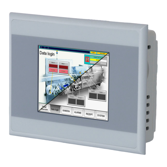
Touch display
Hide thumbs
Also See for XV-102:
- Manual (80 pages) ,
- Operating instructions manual (78 pages) ,
- Quick start manual (16 pages)
Table of Contents
Advertisement
Quick Links
Advertisement
Table of Contents

Related Manuals for Eaton XV-102


Summary of Contents for Eaton XV-102
- Page 1 Operating Instructions 08/2016 MN04802004Z EN XV-102 Touch display...
- Page 2 No part of this manual may be reproduced in any form (printed, photocopy, microfilm or any other process) or processed, duplicated or distributed by means of electronic systems without written permission of Eaton Industries GmbH, Bonn. Subject to alteration without notice.
-
Page 3: Table Of Contents
Occupational safety..................... 3.3.2 Personnel qualifications ....................3.3.3 Operating manual......................3.3.4 Installation, maintenance, and disposal ..............3.3.5 Prohibited use ......................3.3.6 Prerequisites for proper operation................Device-specific hazards ....................Operating and indication elements ................. Overview ........................Touch display XV-102 08/2016 MN04802004Z EN www.eaton.com... - Page 4 Maintenance........................ 7.2.1 Cleaning the resistive touchscreen ................7.2.2 Recalibrating the resistive touchscreen ..............7.2.3 Battery......................... Maintenance........................ 7.3.1 Repairs........................Troubleshooting ......................Storage, transport and disposal ................Safety regulations ....................... Storage........................transport ........................Disposal ........................MICRO PANEL XV-102 08/2016 MN04802004Z EN www.eaton.com...
- Page 5 9.5.2 SmartWire-DT Master ....................9.5.2.1 POW/AUX (power supply interface for SmartWire-DT)..........9.5.2.2 SWD (SmartWire-DT interface)................... IP degrees of protection on the device................ Approvals and declarations..................Applied standards and directives ................Environmental conditions .................... Touch display XV-102 08/2016 MN04802004Z EN www.eaton.com...
- Page 6 Contents MICRO PANEL XV-102 08/2016 MN04802004Z EN www.eaton.com...
-
Page 7: General
✓ Purpose of these Operating manuals These Operating manuals contain the information required for the correct and safe use of the XV-102 touch display. The Operating manuals are part of the devices and must therefore be kept nearby. These Operating manuals describe all aspects of the devices: transport, installation, commissioning, operation, maintenance, storage and disposal. -
Page 8: Further Reading
For the latest information on the product, please visit the Automation, Control & Visualization section at: http://www.eaton.eu/xv Eaton Online Catalog http://www.eaton.eu/ecat Enter "XV100" into the search box and the catalog will take you directly to the corresponding product group in the Automation, Control and visualization section. HMI/PLC XV-102 08/2016 MN04802004Z-EN www.eaton.com... -
Page 9: Description Of Device
2.1 Function Description of device Function Touch displays XV-102 can be used as HMI devices or as integrated HMI/PLC devices. Intended use Touch displays XV-102 are primarily intended for use in machine and system building applications. They are intended exclusively for monitoring, operating, and controlling machines and systems. Any other use must be discussed and agreed upon with the manufacturer in advance. - Page 10 Version E: Resistive touch, CAN, RS485 and SmartWire-DT master XV-102-E6-57TVR… 1 Slot for 1 SD-card 5.7" TFT-LCD, 64K colors, Profibus, RS485 and SmartWire-DT master XV-102-E8-57TVR… Integrated interfaces: 1 Ethernet 100/10 Resistive touch, CAN, RS485 and SmartWire-DT master XV-102-E6-70TWR…...
-
Page 11: Package Contents
If necessary, you can order stylus pens in groups of five (ACCESSORIES-TP-PEN-10, ar- ticle no. 139808), as well as other accessories. Please contact the supplier. The accessories supplied with the XV-102 touch display depend on the size of the device. 2.4.1 3.5"... -
Page 12: Devices
Mounting brackets with grub screw for flush mounting Sealing strip for mounting the device (glued in the device and/or loose enclosed) Power supply connector for the device Power supply connector for SmartWire-DT Master (only supplied with XV-102-E…- devices) Tab. 3 Package contents for 5.7" devices 2.4.3... -
Page 13: Marking
Permissible mounting options (top edge «Top») Support To get fast and effective support, make sure to always provide Customer Service with the following information from the nameplate: Article No. (part No. or article No.) Serial No. HMI/PLC XV-102 08/2016 MN04802004Z-EN www.eaton.com... -
Page 14: Marine Approvals
2 Description of device 2.7 Marine approvals Marine approvals Obtained type approvals The touch displays HMI/PLC XV-102 have been granted the required ship- ping classification by Det Norsk Veritas / Germanischer Lloyd (DNV GL) DNVGL-CG-0339 type approval, November 2015 edition, ... -
Page 15: Safety Regulations
Read this chapter before working with the device. This contains important information for your personal safety. This chapter must be read and understood by all persons work- ing with this device. HMI/PLC XV-102 08/2016 MN04802004Z-EN www.eaton.com... -
Page 16: Precautionary Statements
Indicates a situation that could result in property damage if it is not avoided. Used to highlight useful information. The hazard symbol used and the corresponding text will provide information regarding the specific hazard and how to avoid or prevent it. HMI/PLC XV-102 08/2016 MN04802004Z-EN www.eaton.com... -
Page 17: Mandatory Requirements, Personnel Requirements
Make sure that the device is connected, installed, serviced, and disposed of professionally and in line with all relevant standards and safety rules. 3.3.5 Prohibited use The implementation of safety functions (relating to the protection of personnel and machinery) using the device is prohibited. HMI/PLC XV-102 08/2016 MN04802004Z-EN www.eaton.com... -
Page 18: Prerequisites For Proper Operation
Device failures or function disturbances Improper use and/or handling Failure to observe the Operating manuals Alterations, changes, and repairs to the device Repairs, see Chapter 7.3.1 Repairs, 62. HMI/PLC XV-102 08/2016 MN04802004Z-EN www.eaton.com... -
Page 19: Device-Specific Hazards
Electrostatic discharge may damage or destroy electronic components. Avoid contact with components (such as connector pins) that are susceptible to electrostatic discharge. Discharge (by touching a grounded metal object) any static charge accumulated in your body before touching the device. HMI/PLC XV-102 08/2016 MN04802004Z-EN www.eaton.com... - Page 20 If the device has condensation in or on it, or if the device has been exposed to temperature fluctuations, let the device settle into the existing ambient air tem- perature before switching it on (do not expose the device to direct thermal radia- tion from heating appliances). HMI/PLC XV-102 08/2016 MN04802004Z-EN www.eaton.com...
- Page 21 Do not use any pointy or sharp objects (e.g., knives) to clean the device. Do not use aggressive or abrasive cleaning products or solvents. Prevent liquids from getting into the device (short-circuit hazard). HMI/PLC XV-102 08/2016 MN04802004Z-EN www.eaton.com...
- Page 22 3 Safety regulations 3.4 Device-specific hazards HMI/PLC XV-102 08/2016 MN04802004Z-EN www.eaton.com...
-
Page 23: Operating And Indication Elements
Detection of the actuation of the operating elements shown on the display. These devices are operated by touching the operating elements with your finger or with a stylus. D SD slot 0 Slot for SD card. Tab. 5 Operating and indication elements HMI/PLC XV-102 08/2016 MN04802004Z-EN www.eaton.com... - Page 24 4 Operating and indication elements 4.1 Overview HMI/PLC XV-102 08/2016 MN04802004Z-EN www.eaton.com...
-
Page 25: Installation
The following DNV GL rules for shipping classification in accordance with DNVGL-CG-0339 type approvals must be observed: Complete and proper installation and commissioning in accordance with DNV GL rules and Eaton requirements and specifications. Installation of radio interference suppression filters for the 24 V DC supply. -
Page 26: Requirements For The Mounting Position
Mounting surface characteristics: Material thickness at the mounting cutout 2…5 mm Flatness 0.5 mm (this requirement must also be fulfilled when the device is mounted!) Surface roughness Rz 120 HMI/PLC XV-102 08/2016 MN04802004Z-EN www.eaton.com... -
Page 27: Interfaces
sponding port/interface. All general Directives and standards must be complied with. CAUTION Non-galvanically-isolated interfaces The device may be damaged by potential differences. The GND terminals of all bus modules must be connected. HMI/PLC XV-102 08/2016 MN04802004Z-EN www.eaton.com... -
Page 28: Overview Of Interfaces
The interfaces will vary depending upon the device version. See nameplate and Chapter 2.3 Device models, 9. Fig.. 6 Interfaces of the 3.5" devices Fig.. 7 Interface of the 5.7" and 7.0" devices HMI/PLC XV-102 08/2016 MN04802004Z-EN www.eaton.com... - Page 29 Chapter 5.3.9, 43 Chapter 5.3.10, 46 Profibus Chapter 5.3.4, 34 RS232 (System Port) Chapter 5.3.11, 49 RS485 Chapter 5.3.3, 32 F Power supply Tab. 6 Overview of interfaces HMI/PLC XV-102 08/2016 MN04802004Z-EN www.eaton.com...
-
Page 30: Preparation Of Cables With D-Sub Connector
The folded screen braid end must be covered by the heat-shrink tubing or the rubber grommet. Fit the D-Sub connector to the cable end: The exposed metal screen braid must be clamped to the connector casing with the cable clamp. HMI/PLC XV-102 08/2016 MN04802004Z-EN www.eaton.com... - Page 31 B Heat-shrink tubing or rubber grommet E D-sub plug C Strap F Fixing screw UNC The EMC values stated in the technical data (immunity and emission) can only be guar- anteed by observing the prescribed cable preparation! HMI/PLC XV-102 08/2016 MN04802004Z-EN www.eaton.com...
-
Page 32: Power Supply
/ max. 2.5 mm (drain wire or conductor) min. AWG18 / max. AWG12 Strip length 7 mm Max. tightening torque 0.6…0.8 Nm / 5…7 Lb. In. Tab. 8 Terminating the wiring with the plug connector HMI/PLC XV-102 08/2016 MN04802004Z-EN www.eaton.com... - Page 33 Integrate a radio interference suppression filter into the wiring. Depending on the output, the following filters can be used: XT-FIL-1 radio interference suppression filter for 24 V DC supply up to 2.2 A (Eaton article no. 285316) XT-FIL-2 radio interference suppression filter for 24 V DC supply up to 12 A (Eaton article no.
-
Page 34: Rs232 (System Port)
9600 Bit/s Tab. 10 Relationship of cable length / baud rate When preparing the cables, ensure that there is a low-resistance connection between the cable screen and the connector casing ( Chapter 5.3.2, 30). HMI/PLC XV-102 08/2016 MN04802004Z-EN www.eaton.com... -
Page 35: Ethernet
Ethernet interface is subjected to strong vibrations or the RJ45 plug-in connection is subjected to pulling. Protect the RJ45 plug-in connection from strong vibrations. Protect the RJ45 plug-in connection from tensile forces at the socket. HMI/PLC XV-102 08/2016 MN04802004Z-EN www.eaton.com... -
Page 36: Usb Device
5.3.7 USB Host The USB Host interface supports USB 2.0. Fig.. 16 USB Host interface (USB Host, type A) Cable Only use standard USB cables with a screen. Maximum cable length: 5 m. HMI/PLC XV-102 08/2016 MN04802004Z-EN www.eaton.com... -
Page 37: Smartwire-Dt Master
Windows CE) The documents can be downloaded from: www.eaton.eu/doc (search for the document number using the search field on the home page) www.eaton.com (search for the document number using the search field on the home page) ... -
Page 38: Operating And Indication Elements Of The Smartwire-Dt Master Interface
( Chapter 5.3.8.5, 41). E Configuration button Configure SmartWire-DT network. F SWD Interface SmartWire-DT interface ( Chapter 5.3.8.4, 40) Tab. 12 Operating and indication elements of the SmartWire-DT master interface HMI/PLC XV-102 08/2016 MN04802004Z-EN www.eaton.com... -
Page 39: Pow/Aux (Power Supply For Smartwire-Dt)
Connectable conductor, solid 0.2…1.5 mm (AWG24…16) Strip length 6…7 mm Tab. 14 Terminating the wiring with the plug connector External overcurrent and short-circuit protective device, implemented with a miniature circuit- breaker or a fuse, is required for U HMI/PLC XV-102 08/2016 MN04802004Z-EN www.eaton.com... -
Page 40: Swd (Smartwire-Dt Interface)
SWD4-100LF8-24 with the relevant blade terminals SWD4-8MF2 or SWD4-(3/5/10)F8-24-2S (prefabricated cable) Detailed instructions on fitting the blade terminal SWD4-8MF2 are provided in the Doc- ument «SmartWire-DT The System Manual MN05006002Z», Chapter «Fitting the blade terminal SWD4-8MF2». HMI/PLC XV-102 08/2016 MN04802004Z-EN www.eaton.com... -
Page 41: Commissioning The Smartwire-Dt Network
Download the PLC project (XSoft-CoDeSys-2) onto the device. If the project configuration is identical to the stored target configuration, the Config LED lights up green and the data exchange of the input and output data can start. HMI/PLC XV-102 08/2016 MN04802004Z-EN www.eaton.com... - Page 42 The description of the project configuration (SmartWire-DT configuration in XSoft-COD- ESYS project) are provided in the Document «User Manual XSOFT-CODESYS 2 MN04802091Z, PLC programming» or «User Manual XSOFT-CODESYS 3 MN048008ZU, PLC programming», Chapter «SmartWire-DT configuration». HMI/PLC XV-102 08/2016 MN04802004Z-EN www.eaton.com...
-
Page 43: Can
Pin 1, 4, 5, 8 and 9 must not be connected. The power supply of the CAN bus drivers is implemented internally. A power supply for third party devices is not provided on the CAN connector. HMI/PLC XV-102 08/2016 MN04802004Z-EN www.eaton.com... - Page 44 Observe the recommendations of CiA (CAN in Automation). When preparing the cables, ensure that there is a low-resistance connection between the cable screen and the connector casing ( Chapter 5.3.2, 30). HMI/PLC XV-102 08/2016 MN04802004Z-EN www.eaton.com...
- Page 45 The bus segment must be terminated at both ends. No more than two terminations must be provided for each bus segment. Operation without correct cable termination can cause transfer errors. Fig.. 22 Bus segment with four nodes HMI/PLC XV-102 08/2016 MN04802004Z-EN www.eaton.com...
-
Page 46: Profibus
Output 5 V for external termination EIA RS 485 line A Tab. 20 Pin assignment of the Profibus interface Pin 6 (5 V) must not be used as a power supply for external devices. HMI/PLC XV-102 08/2016 MN04802004Z-EN www.eaton.com... - Page 47 Tab. 22 Relationship of cable length / baud rate (for cables compliant with cable type A of the Profibus standard IEC/EN 61158 and IEC/EN 61784) When preparing the cables, ensure that there is a low-resistance connection between the cable screen and the connector casing ( Chapter 5.3.2, 30). HMI/PLC XV-102 08/2016 MN04802004Z-EN www.eaton.com...
- Page 48 No more than two terminations must be provided for each bus segment. At least one of the two terminations must be fed by the bus station. Operation without correct termination of the Profibus network can cause transfer er- rors. HMI/PLC XV-102 08/2016 MN04802004Z-EN www.eaton.com...
-
Page 49: Rs485
Fig.. 25 RS485 interface (9-pin, D-Sub, male, UNC) Signal Configuration Line B Ground Line A Tab. 23 Pin assignment of the RS485 interface nc: Pin 1, 2, 4, 6, 8 and 9 must not be connected. HMI/PLC XV-102 08/2016 MN04802004Z-EN www.eaton.com... - Page 50 The bus segment must be terminated at both ends. No more than two terminations must be provided for each bus segment. Operation without correct cable termination can cause transfer errors. Fig.. 26 Bus segment with four nodes HMI/PLC XV-102 08/2016 MN04802004Z-EN www.eaton.com...
-
Page 51: Mounting
The device does not have an ON/OFF switch. The device is not provided with an On/Off switch. If the power supply is not provided with a switch, the device will start up (boot) as soon as it is connected to the power supply. HMI/PLC XV-102 08/2016 MN04802004Z-EN www.eaton.com... -
Page 52: Mounting The Device
Material thickness at the mounting cutout 2…5 mm 123.0 157.0 +1/-1 +1/-1 Fig.. 27 Mounting cutout for 3.5" devices Fig.. 28 Mounting cutout for 5.7" devices 197.0 +1/-1 Fig.. 29 Mounting cutout for 7.0" devices HMI/PLC XV-102 08/2016 MN04802004Z-EN www.eaton.com... - Page 53 Clip on the retaining brackets in the recesses provided for them on the device as shown below and fix the device by tightening the threaded pins until the front of the MICRO PANEL is flush with the surface of the control cabinet at the fixing points. HMI/PLC XV-102 08/2016 MN04802004Z-EN www.eaton.com...
- Page 54 Fig.. 33 5.7" devices with four retaining brackets (do not meet IP65 / NEMA 4X requirements) 5.7" devices which must be mounted in accordance with IP65 / NEMA 4X or used in potentially explosive atmospheres: One retaining bracket each at all six fixing positions HMI/PLC XV-102 08/2016 MN04802004Z-EN www.eaton.com...
- Page 55 7.0" devices which must be mounted in accordance with IP65 / NEMA 4X or used in potentially explosive atmospheres: One retaining bracket each at all eight fixing positions Fig.. 36 7.0" devices with eight retaining brackets (meet IP65 / NEMA 4X requirements) HMI/PLC XV-102 08/2016 MN04802004Z-EN www.eaton.com...
-
Page 56: Screening The Communication Cables Used
Fig.. 37 Screening with snap-together ferrite ring 2.7 Marine approvals, 14 5.2.2 Conditions for marine approval (DNV GL), 25 5.3.3 Section Radio interference suppression filter for the 24 V DC supply, 33 HMI/PLC XV-102 08/2016 MN04802004Z-EN www.eaton.com... -
Page 57: Operation
If the device has condensation in or on it, or if the device has been exposed to temperature fluctuations, let the device settle into the existing ambient air tem- perature before switching it on (do not expose the device to direct thermal radia- tion from heating appliances). HMI/PLC XV-102 08/2016 MN04802004Z-EN www.eaton.com... -
Page 58: Starting The Device
The lifespan of the backlight can be increased by reducing the brightness ( Document «System Description Windows CE MN05010007Z (operation of the Windows CE operat- ing system on touch displays)»). Switch off the device De-energize the device. HMI/PLC XV-102 08/2016 MN04802004Z-EN www.eaton.com... -
Page 59: Inserting And Removing The Sd Card
Push the SD card in the SD slot (A) all the way in. This releases the lock mechanism and the SD card comes out of the SD slot a little. Remove the SD card from the SD slot. HMI/PLC XV-102 08/2016 MN04802004Z-EN www.eaton.com... - Page 60 6 Operation 6.4 Inserting and removing the SD card HMI/PLC XV-102 08/2016 MN04802004Z-EN www.eaton.com...
-
Page 61: Maintenance And Repairs
Touch calibration, see Document «System Description Windows CE MN05010007Z (operation of the Windows CE operating system on touch displays)». 7.2.3 Battery The integrated battery cannot be exchanged. Lifespan, see Chapter 9.4 System, 71 HMI/PLC XV-102 08/2016 MN04802004Z-EN www.eaton.com... -
Page 62: Maintenance
Repairs The device should only be opened by the manufacturer or by an authorized repair center. Contact your local supplier or Eaton technical support for repairs. Only the original packaging should be used for transporting the device. HMI/PLC XV-102 08/2016 MN04802004Z-EN www.eaton.com... -
Page 63: Troubleshooting
The set screws used to mount the device are Loosen the threaded pins (observe max. torque, Chapter 5.4.1, 52) too tight. The device is faulty. Send the device in for repairs. HMI/PLC XV-102 08/2016 MN04802004Z-EN www.eaton.com... - Page 64 7 Maintenance and repairs 7.4 Troubleshooting Tab. 25 Troubleshooting HMI/PLC XV-102 08/2016 MN04802004Z-EN www.eaton.com...
-
Page 65: Storage, Transport And Disposal
When transporting or shipping the device, make sure that the device is not damaged (use appropriate packaging). All ambient conditions need to be met during transportation and shipping as well. See chapter 9.9 Envi- ronmental conditions, 78 Check the device for transit damage after arrival. HMI/PLC XV-102 08/2016 MN04802004Z-EN www.eaton.com... -
Page 66: Disposal
External packaging Cardboard Internal packaging: 3.5" devices Cardboard with PE sheet Plastic bag: polyethylene (PE) 5.7" and 7.0" devices Cardboard Plastic bag: polyethylene (PE) Tab. 27 Materials used in the packaging HMI/PLC XV-102 08/2016 MN04802004Z-EN www.eaton.com... -
Page 67: Technical Data
Depth 30 mm Thickness of front plate 5 mm Built-in depth 25 mm 123 mm 87 mm (±1 mm) Installation cut-out Weight Approx. 0.3 kg Tab. 28 Dimensions and weights of the 3.5" devices HMI/PLC XV-102 08/2016 MN04802004Z-EN www.eaton.com... -
Page 68: Devices
Depth 39 mm Thickness of front plate 5 mm Built-in depth 34 mm 157 mm 117 mm (±1 mm) Installation cut-out Weight Approx. 0.6 kg Tab. 29 Dimensions and weights of the 5.7" devices HMI/PLC XV-102 08/2016 MN04802004Z-EN www.eaton.com... -
Page 69: Devices
Depth 38 mm Thickness of front plate 5 mm Built-in depth 33 mm 197 mm 122 mm (±1 mm) Installation cut-out Weight Approx. 0.6 kg Tab. 30 Dimensions and weights of the 7.0" devices HMI/PLC XV-102 08/2016 MN04802004Z-EN www.eaton.com... -
Page 70: Display
100 % … 20 % brightness lifespan Normally 40 000 h Resistive touch protective screen Touch sensor (glass with foil) Tab. 31 Display Touch sensor Property XV-102 Part no. Resistive-Touch Technology 4 conductor Tab. 32 Touch sensor HMI/PLC XV-102 08/2016 MN04802004Z-EN www.eaton.com... -
Page 71: System
Suitable for SD cards (not for SDHC cards or cards of newer standard) Only use original accessories. Real-time clock (battery back-up) Battery type CR2032 (190 mA/h), maintenance-free (soldered) Backup time at zero voltage Normally 10 years Tab. 33 System HMI/PLC XV-102 08/2016 MN04802004Z-EN www.eaton.com... -
Page 72: Interfaces
CAN, not galvanically isolated Profibus Profibus, not electrically isolated, max. 1.5 Mbit/s RS485 RS485, not galvanically isolated Chapter 9.5.1, 73 Power supply DIAG Only for service tasks UPD/RUN jumper Only for service tasks Tab. 34 Interfaces HMI/PLC XV-102 08/2016 MN04802004Z-EN www.eaton.com... - Page 73 5.7" and 7.0" devices Max. 0.4 A (24 VDC) Starting current inrush 1.5 A Protection against polarity reversal fuse Yes (replacement only by the manufacturer or by an authorized repair center) Potential isolation Tab. 35 Power supply HMI/PLC XV-102 08/2016 MN04802004Z-EN www.eaton.com...
-
Page 74: Pow/Aux (Power Supply Interface For Smartwire-Dt)
Protection against polarity reversal Current Max. 0.7 A Overload proof Inrush current and length 12.5 A/6 ms Heat dissipation at 24 VDC 1.0 W Potential isolation between U 15 V SmartWire-DT supply voltage Bridging voltage dips 10 ms HMI/PLC XV-102 08/2016 MN04802004Z-EN www.eaton.com... -
Page 75: Swd (Smartwire-Dt Interface)
250 kBit/s (= default settings) Tab. 37 SWD (SmartWire-DT interface) 1) If SmartWire-DT modules with a total current draw > 0.7 A are connected, an EU5C-SWD-PF2 power feeder module needs to be used. HMI/PLC XV-102 08/2016 MN04802004Z-EN www.eaton.com... -
Page 76: Ip Degrees Of Protection On The Device
DNVGL-CG-0039, since 11/2015 Certificate No.: TAA00000NC Tab. 39 Approvals and declarations 1) Zone 22, category 3D: - IP5x for group IIIB devices (nonconductive dust) - IP6x for group IIIC devices (conductive dust) HMI/PLC XV-102 08/2016 MN04802004Z-EN www.eaton.com... -
Page 77: Applied Standards And Directives
Product standards EN 50178 Electronic equipment for use in power installations IEC/EN 61131-2 Programmable logic controllers: Equipment require- ments and tests Tab. 40 Applied standards and directives Fig.. 42 Ethernet cable, double loop through ferrite HMI/PLC XV-102 08/2016 MN04802004Z-EN www.eaton.com... -
Page 78: Environmental Conditions
5…9 Hz: 3.5 mm 9…60 Hz: 0.15 mm Acceleration: 60…150 Hz: 2 g Shock as per IEC/EN 60068-2-27 15 g / 11 ms Fall test in accordance to IEC/EN 60068-2-31 Tab. 41 Ambient conditions HMI/PLC XV-102 08/2016 MN04802004Z-EN www.eaton.com... - Page 79 At Eaton, we’re energized by the challenge of powering a world that Eaton addresses worldwide: demands more. With over 100 years experience in electrical power www.eaton.com management, we have the expertise to see beyond today. From groundbreaking products to turnkey design and engineering services, critical industries around the globe count on Eaton.
Need help?
Do you have a question about the XV-102 and is the answer not in the manual?
Questions and answers