Eaton XV-102 Operating Instructions Manual
Micro panel
Hide thumbs
Also See for XV-102:
- Manual (80 pages) ,
- Operating instructions manual (79 pages) ,
- Quick start manual (16 pages)

Related Manuals for Eaton XV-102


Summary of Contents for Eaton XV-102
- Page 1 XV-102 Micro Panel Operating Instructions Effective February 2013 Supersedes December 2011 www.comoso.com...
- Page 2 All rights reserved, also for the translation. None of this document may be reproduced or processed, duplicated or distributed by electronic systems in any form (print, photocopy, microfilm or any other process) without the written permission of Eaton Automation AG, St. Gallen. Subject to modifications. www.comoso.com...
-
Page 3: Table Of Contents
Preparation of cables with D-Sub connector............... 5.3.3 Power supply....................... 5.3.4 RS232 (System Port) ....................5.3.5 Ethernet........................5.3.6 USB Device......................... 5.3.7 USB Host ........................5.3.8 SmartWire-DT Master ....................5.3.8.1 Additional documentation for devices with SmartWire-DT Master interface ....XV-102 Micro Panel MN04802004Z-EN—February 2013 www.eaton.com www.comoso.com... - Page 4 Interfaces ........................9.5.1 Power supply....................... 9.5.2 SmartWire-DT Master ....................9.5.2.1 POW/AUX (power supply interface for SmartWire-DT)..........9.5.2.2 SWD (SmartWire-DT interface)................... Enclosure ratings ......................Agency approvals and standards................Applicable standards and regulations ................. Ambient conditions...................... XV-102 Micro Panel MN04802004Z-EN—February 2013 www.eaton.com www.comoso.com...
-
Page 5: General
Purpose of these Operating Instructions These Operating Instructions contain the information required for the correct and safe use of the MICRO PANELs XV-102. The Operating Instructions are part of the devices and must therefore be kept nearby. These Operating Instructions describe all aspects of the devices: transport, installation, commissioning, operation, maintenance, storage and disposal. -
Page 6: Additional Documentation
(information on networks in general and on the integration of PCs and MICRO PANELs in networks) The documents can also be downloaded from www.eaton.com (search document No. via search field of the home page). Documents relevant for the devices with SmartWire-DT Master interface, see Chapter 5.3.8 SmartWire-DT Master,... -
Page 7: Device Description
MICRO PANELs XV-102 can be used as HMI devices or as integrated HMI/PLC devices. Intended use MICRO PANELs XV-102 are primarily used in machine and system building. They are designed exclu- sively for the visualization, operation and control of machines and systems. Any other use must be agreed beforehand with the manufacturer. -
Page 8: Device Versions
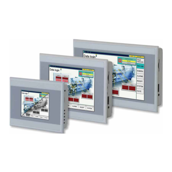
2 Device description 2.3 Device versions Device versions Fig. 1 XV-102 3.5" Fig. 2 XV-102 5.7" Fig. 3 XV-102 7.0" MICRO PANELs XV-102 are available in the following versions: Basic device Display Communication interfaces XV-102 type Version A: Resistive touch, –... - Page 9 Version E: Resistive touch, CAN, RS485 and SmartWire-DT Master XV-102-E6-57TVR… 1 Slot for 1 SD card 5.7" TFT-LCD, 64k colors, Profibus, RS485 and SmartWire-DT Master XV-102-E8-57TVR… Integrated interfaces: 1 Ethernet 100/10 Resistive touch, CAN, RS485 and SmartWire-DT Master XV-102-E6-70TWR… 1 USB Device 7.0"...
-
Page 10: Package Contents
2 Device description 2.4 Package contents Package contents The accessories supplied with the MICRO PANELs XV-102 depend on the size of the device. 2.4.1 3.5" devices Designation MICRO PANEL: XV-102-…-35MQR… or XV-102-…-35TQR… Retaining brackets with threaded pin for mounting the device... -
Page 11: Devices
Retaining brackets with threaded pin for mounting the device Sealing strip for mounting the device (glued in the device and/or loose enclosed) Power supply connector for the device Power supply connector for SmartWire-DT Master (only supplied with XV-102-E… devices) Stylus Tab. 4 Package contents for 7.0" devices Accessories Different accessories are available. - Page 12 2 Device description 2.6 Designation XV-102 Micro Panel MN04802004Z-EN—February 2013 www.eaton.com www.comoso.com...
-
Page 13: Safety Regulations
Read this chapter before working with the device. This contains important information for your personal safety. This chapter must be read and understood by all persons work- ing with this device. XV-102 Micro Panel MN04802004Z-EN—February 2013 www.eaton.com www.comoso.com... -
Page 14: Meaning Of Symbols
Signal word CAUTION without safety alert symbol Indicates a situation which, if not avoided, could result in material damage. Indicates useful information. The danger symbol used and the text indicate the actual danger and the related preventative measures. XV-102 Micro Panel MN04802004Z-EN—February 2013 www.eaton.com www.comoso.com... -
Page 15: Mandatory Requirements, Personnel
It must be ensured that the device is properly connected, mounted, maintained and disposed of in compliance with all relevant standards and safety regulations. 3.3.5 Prohibited use The implementation of safety functions (relating to the protection of personnel and machinery) using the device is prohibited. XV-102 Micro Panel MN04802004Z-EN—February 2013 www.eaton.com www.comoso.com... -
Page 16: Requirements For Proper Operation
Failure to observe work safety regulations Failure or malfunction of the device Improper handling or use Failure to observe the Operating Instructions Conversions, modifications and repairs to the device Repairs, see Chapter 7.3.1 Repairs, XV-102 Micro Panel MN04802004Z-EN—February 2013 www.eaton.com www.comoso.com... -
Page 17: Device Related Hazards
Electrostatic discharge may damage or destroy electronic components. Avoid contact with components (such as connector pins) that are susceptible to electrostatic discharge. Discharge (by touching a grounded metal object) any static charge accumulated in your body before touching the device. XV-102 Micro Panel MN04802004Z-EN—February 2013 www.eaton.com www.comoso.com... - Page 18 CAUTION UV light When exposed to UV light, plastics can embrittle and the lifespan of the device is reduced. Protect the device against direct sunlight (UV rays). XV-102 Micro Panel MN04802004Z-EN—February 2013 www.eaton.com www.comoso.com...
- Page 19 Damage to the device due to the use of pointed or sharp objects or by liquids. Do not use any pointed or sharp objects (e.g. knife) for cleaning. Do not use any aggressive or abrasive cleaning agent or solvent. Avoid any liquid entering the device (risk of short-circuit). XV-102 Micro Panel MN04802004Z-EN—February 2013 www.eaton.com www.comoso.com...
- Page 20 3 Safety regulations 3.4 Device related hazards XV-102 Micro Panel MN04802004Z-EN—February 2013 www.eaton.com www.comoso.com...
-
Page 21: Operating And Indication Elements
Detection of the actuation of the operating elements shown on the display. These devices are operated by touching the operating elements with your finger or with a stylus. D SD slot 0 Slot for SD card. Tab. 5 Operating and indication elements XV-102 Micro Panel MN04802004Z-EN—February 2013 www.eaton.com www.comoso.com... - Page 22 4 Operating and indication elements 4.1 Overview XV-102 Micro Panel MN04802004Z-EN—February 2013 www.eaton.com www.comoso.com...
-
Page 23: Installation
5 Installation 5.1 Safety regulations Installation Safety regulations Read Chapter 3 Safety regulations, 11 before installing and commissioning the de- vice. This contains important information for your personal safety. XV-102 Micro Panel MN04802004Z-EN—February 2013 www.eaton.com www.comoso.com... -
Page 24: Requirements For The Place Of Installation
The expected temperatures should be within the permissible range. See Chapter 9.9 Ambient conditions, Properties of the mounting surfaces: Material thickness at the mounting cutout 2…5 mm Flatness 0.5 mm (this requirement must also be fulfilled when the device is mounted!) Surface roughness Rz 120 XV-102 Micro Panel MN04802004Z-EN—February 2013 www.eaton.com www.comoso.com... -
Page 25: Interfaces
Any generally applicable regulations and standards must be fulfilled. CAUTION Non-isolated interfaces The device may be damaged due to potential differences. The GND terminals of all bus stations must be connected. XV-102 Micro Panel MN04802004Z-EN—February 2013 www.eaton.com www.comoso.com... -
Page 26: Overview Of Interfaces
Overview of interfaces The interfaces will vary depending upon the device version. See nameplate and Chapter 2.3 Device versions, Fig. 6 Interfaces of the 3.5" devices Fig. 7 Interface of the 5.7" and 7.0" devices XV-102 Micro Panel MN04802004Z-EN—February 2013 www.eaton.com www.comoso.com... - Page 27 E Interfaces, depending on the device version: USB Host Chapter 5.3.7, SmartWire-DT Master Chapter 5.3.8, Chapter 5.3.9, Profibus Chapter 5.3.11, RS232 (System Port) Chapter 5.3.4, RS485 Chapter 5.3.11, F Power supply Chapter 5.3.3, Tab. 6 Overview of interfaces XV-102 Micro Panel MN04802004Z-EN—February 2013 www.eaton.com www.comoso.com...
-
Page 28: Preparation Of Cables With D-Sub Connector
The folded back shield braid end must be covered by the heat shrinkable tubing or by the rubber grommet. Fit the D-Sub connector to the cable end: The exposed metal shield braid must be clamped to the connector casing with the cable clamp. XV-102 Micro Panel MN04802004Z-EN—February 2013 www.eaton.com www.comoso.com... - Page 29 B Heat shrinkable tubing or rubber grommet E D-Sub connector C Cable clamp F Mounting screw UNC The EMC values stated in the technical data (immunity and emission) can only be guar- anteed by observing the prescribed cable preparation! XV-102 Micro Panel MN04802004Z-EN—February 2013 www.eaton.com www.comoso.com...
-
Page 30: Power Supply
/ max. 2.5 mm (lead or wire) min. AWG18 / max. AWG12 Stripping length 7 mm Max. tightening torque 0.6…0.8 Nm / 5…7 Lb. In. Tab. 8 Preparing the wiring of the connector XV-102 Micro Panel MN04802004Z-EN—February 2013 www.eaton.com www.comoso.com... -
Page 31: Rs232 (System Port)
The maximum baud rate depends on the cable length: Cable length Max. baud rate 2.5 m 115200 Bit/s 57600 Bit/s 10 m 38400 Bit/s 15 m 19200 Bit/s 30 m 9600 Bit/s Tab. 10 Relationship of cable length / baud rate XV-102 Micro Panel MN04802004Z-EN—February 2013 www.eaton.com www.comoso.com... - Page 32 5 Installation 5.3 Interfaces When preparing the cables, ensure that there is a low-resistance connection between the cable shield and the connector casing ( Chapter 5.3.2, 26). XV-102 Micro Panel MN04802004Z-EN—February 2013 www.eaton.com www.comoso.com...
-
Page 33: Ethernet
Communication can be disturbed and the connection mechanics damaged if the Ethernet interface is exposed to severe vibration or the RJ45 plug connection is pulled. Protect the RJ45 connection from severe vibration. Protect the RJ45 connection from pulling on the socket. XV-102 Micro Panel MN04802004Z-EN—February 2013 www.eaton.com www.comoso.com... -
Page 34: Usb Device
Maximum cable length: 5 m. 5.3.7 USB Host The USB Host interface supports USB 2.0. Fig. 15 USB Host interface (USB Host, type A) Cable Only use shielded USB standard cable. Maximum cable length: 5 m. XV-102 Micro Panel MN04802004Z-EN—February 2013 www.eaton.com www.comoso.com... -
Page 35: Smartwire-Dt Master
(Use of the PLC programming tool XSoft-CoDeSys-2 and the PLC runtime system for the XV100 device type with Windows CE) The documents can also be downloaded from www.eaton.com (search document No. via search field of the home page). XV-102 Micro Panel MN04802004Z-EN—February 2013 www.eaton.com... -
Page 36: Operating And Indication Elements Of The Smartwire-Dt Master Interface
( Chapter 5.3.8.5, 37). E Configuration button Configuring the SmartWire-DT network. F SWD interface SmartWire-DT interface ( Chapter 5.3.8.4, Tab. 12 Operating and indication elements of the SmartWire-DT Master interface XV-102 Micro Panel MN04802004Z-EN—February 2013 www.eaton.com www.comoso.com... -
Page 37: Pow/Aux (Power Supply For Smartwire-Dt)
The following must be observed when the connector wiring is prepared: Preparing the wiring of the connector Terminal type Tension clamp terminal Crimpable wire solid 0.2…1.5 mm (AWG24…16) Stripping length 6…7 mm Tab. 14 Preparing the wiring of the connector XV-102 Micro Panel MN04802004Z-EN—February 2013 www.eaton.com www.comoso.com... -
Page 38: Swd (Smartwire-Dt Interface)
SWD4-100LF8-24 with the relevant blade terminals SWD4-8MF2 or SWD4-(3/5/10)F8-24-2S (prefabricated cable) Detailed instructions on fitting the blade terminal SWD4-8MF2 are provided in the Doc- ument «MN05006002Z-EN Manual SmartWire-DT The System», Chapter «Fitting the blade terminal SWD4-8MF2». XV-102 Micro Panel MN04802004Z-EN—February 2013 www.eaton.com www.comoso.com... -
Page 39: Commissioning Of The Smartwire-Dt Netwerk
Download the PLC project (XSoft-CoDeSys-2) onto the device. If the project configuration is identical to the stored target configuration, the Config LED lights up green and the data exchange of the input and output data can start. XV-102 Micro Panel MN04802004Z-EN—February 2013 www.eaton.com www.comoso.com... - Page 40 Tab. 16 SWD LED and Config LED The description of the project configuration (SmartWire-DT configuration in XSoft- CoDeSys-2 project) are provided in the Document «MN04802091Z-EN User Manual XSoft-CoDeSys-2: PLC programming XV100», Chapter «SmartWire-DT configuration». XV-102 Micro Panel MN04802004Z-EN—February 2013 www.eaton.com www.comoso.com...
-
Page 41: Can
Pins 1, 4, 5, 8 and 9 must not be connected. The CAN bus drivers are fed internally with power. No power supply for third-party devices is implemented on the CAN connector. XV-102 Micro Panel MN04802004Z-EN—February 2013 www.eaton.com www.comoso.com... - Page 42 The bus segment must be terminated at both ends. No more than two terminations must be provided on each bus segment. Transmission faults can occur if operation is carried out without the correct termina- tion. XV-102 Micro Panel MN04802004Z-EN—February 2013 www.eaton.com www.comoso.com...
- Page 43 5 Installation 5.3 Interfaces Fig. 21 Bus segment with four bus stations XV-102 Micro Panel MN04802004Z-EN—February 2013 www.eaton.com www.comoso.com...
-
Page 44: Profibus
IEC/EN 61784) must be used. Cable specifications Rated surge impedance Permissible surge impedance 135…165 Capacitance per unit length < 30 pF/m Loop resistance < 110 Core cross-section 0.34 mm (22 AWG) Tab. 21 Cable specifications XV-102 Micro Panel MN04802004Z-EN—February 2013 www.eaton.com www.comoso.com... - Page 45 No more than two terminations must be provided on each bus segment. At least one of the two terminations must be fed by the bus station. Transmission faults can occur if operation is carried out without the correct termina- tion on the Profibus network. XV-102 Micro Panel MN04802004Z-EN—February 2013 www.eaton.com www.comoso.com...
-
Page 46: Rs485
Fig. 24 RS485 interface (9-pin, D-Sub, male, UNC) Signal Assignment Line B Ground Line A Tab. 23 Pin assignment of the RS485 interface nc: Pins 1, 2, 4, 6, 8 and 9 must not be connected. XV-102 Micro Panel MN04802004Z-EN—February 2013 www.eaton.com www.comoso.com... - Page 47 No more than two terminations must be provided on each bus segment. Transmission faults can occur if operation is carried out without the correct termina- tion. Fig. 25 Bus segment with four bus stations XV-102 Micro Panel MN04802004Z-EN—February 2013 www.eaton.com www.comoso.com...
-
Page 48: Mounting
The device is not provided with an On/Off switch. If the power supply is not provided with a switch, the device will start up (boot) as soon as it is connected to the power sup- ply. XV-102 Micro Panel MN04802004Z-EN—February 2013 www.eaton.com www.comoso.com... -
Page 49: Mounting The Device
Material thickness at the mounting cutout 2…5 mm 123.0 157.0 +1/-1 +1/-1 Fig. 26 Mounting cutout for 3.5" devices Fig. 27 Mounting cutout for 5.7" devices 197.0 +1/-1 Fig. 28 Mounting cutout for 7.0" devices XV-102 Micro Panel MN04802004Z-EN—February 2013 www.eaton.com www.comoso.com... - Page 50 The tips of the threaded pins must point towards the wider ends of the retaining brackets. Fig. 30 Threaded pin pre-fitted in a retaining bracket Fit the device from the front into the mounting cutout. XV-102 Micro Panel MN04802004Z-EN—February 2013 www.eaton.com www.comoso.com...
- Page 51 3.5" devices: One retaining bracket each at all four fixing positions Fig. 31 3.5" devices with four retaining brackets (meet IP65 / NEMA 4X requirements) XV-102 Micro Panel MN04802004Z-EN—February 2013 www.eaton.com www.comoso.com...
- Page 52 5.7" devices which must be mounted in accordance with IP65 / NEMA 4X or used in potentially explosive atmospheres: One retaining bracket each at all six fixing positions Fig. 33 5.7" devices with six retaining brackets (meet IP65 / NEMA 4X requirements) XV-102 Micro Panel MN04802004Z-EN—February 2013 www.eaton.com www.comoso.com...
- Page 53 7.0" devices which must be mounted in accordance with IP65 / NEMA 4X or used in potentially explosive atmospheres: One retaining bracket each at all eight fixing positions Fig. 35 7.0" devices with eight retaining brackets (meet IP65 / NEMA 4X requirements) XV-102 Micro Panel MN04802004Z-EN—February 2013 www.eaton.com www.comoso.com...
- Page 54 5 Installation 5.4 Mounting XV-102 Micro Panel MN04802004Z-EN—February 2013 www.eaton.com www.comoso.com...
-
Page 55: Operation
If condensation is present on the device, or if it was exposed to temperature fluc- tuations, it must be allowed to adjust to room temperature (do not expose the de- vice to the direct heat of heating devices) prior to commissioning. XV-102 Micro Panel MN04802004Z-EN—February 2013 www.eaton.com www.comoso.com... -
Page 56: Starting The Device
Adjust the system settings of the device. Install the required application programs. The lifespan of the backlight can be increased by reducing the brightness ( Document «MN05010007Z-EN System Description Windows CE»). Switching off the device De-energize the device. XV-102 Micro Panel MN04802004Z-EN—February 2013 www.eaton.com www.comoso.com... -
Page 57: Inserting And Removing An Sd Card
Push the SD card in the SD slot (A) all the way in. This releases the lock mechanism and the SD card comes out of the SD slot a little. Remove the SD card from the SD slot. XV-102 Micro Panel MN04802004Z-EN—February 2013 www.eaton.com www.comoso.com... - Page 58 6 Operation 6.4 Inserting and removing an SD card XV-102 Micro Panel MN04802004Z-EN—February 2013 www.eaton.com www.comoso.com...
-
Page 59: Maintenance And Service
7 Maintenance and service 7.1 Safety regulations Maintenance and service Safety regulations Read Chapter 3 Safety regulations, 11 before working with the device. This contains important information for your personal safety. XV-102 Micro Panel MN04802004Z-EN—February 2013 www.eaton.com www.comoso.com... -
Page 60: Maintenance
The resistive touch is already calibrated when delivered. However, it must be recalibrated if it does not respond correctly to touch operation. Touch calibration, see Document «MN05010007Z-EN System Description Windows CE». 7.2.3 Battery The integrated battery cannot be exchanged. Lifespan, see Chapter 9.4 System, XV-102 Micro Panel MN04802004Z-EN—February 2013 www.eaton.com www.comoso.com... -
Page 61: Service
Repairs The device must only be opened by the manufacturer or by an authorized repair center. Contact your local supplier or Eaton technical support for repairs. Only the original packaging should be used for transporting the device. XV-102 Micro Panel MN04802004Z-EN—February 2013 www.eaton.com... -
Page 62: Troubleshooting
The threaded pins for mounting the device have Loosen the threaded pins (observe max. been tightened too much. torque, Chapter 5.4.1, 47). Device is faulty. Send in your device for repair. Tab. 25 Troubleshooting XV-102 Micro Panel MN04802004Z-EN—February 2013 www.eaton.com www.comoso.com... -
Page 63: Storage, Transport And Disposal
Damage to the device must be prevented during transport (use an appropriate packaging). The ambient conditions must be fulfilled even when the device is transported. See Chapter 9.9 Ambient conditions, Check the device on arrival for damage in transit. XV-102 Micro Panel MN04802004Z-EN—February 2013 www.eaton.com www.comoso.com... -
Page 64: Disposal
Packaging Material External packaging Cardboard Internal packaging: 3.5" devices Cardboard with PE foil Plastic bag: Polyethylene (PE) 5.7" and 7.0" devices Cardboard Plastic bag: Polyethylene (PE) Tab. 27 Materials used in the packaging XV-102 Micro Panel MN04802004Z-EN—February 2013 www.eaton.com www.comoso.com... -
Page 65: Technical Data
30 mm Thickness of front plate 5 mm Mounting depth 25 mm Mounting cutout 123 mm 87 mm (±1 mm) Weight Approx. 0.3 kg Tab. 28 Dimensions and weights of the 3.5" devices XV-102 Micro Panel MN04802004Z-EN—February 2013 www.eaton.com www.comoso.com... -
Page 66: Devices
39 mm Thickness of front plate 5 mm Mounting depth 34 mm Mounting cutout 157 mm 117 mm (±1 mm) Weight Approx. 0.6 kg Tab. 29 Dimensions and weights of the 5.7" devices XV-102 Micro Panel MN04802004Z-EN—February 2013 www.eaton.com www.comoso.com... -
Page 67: Devices
38 mm Thickness of front plate 5 mm Mounting depth 33 mm Mounting cutout 197 mm 122 mm (±1 mm) Weight Approx. 0.6 kg Tab. 30 Dimensions and weights of the 7.0" devices XV-102 Micro Panel MN04802004Z-EN—February 2013 www.eaton.com www.comoso.com... -
Page 68: Display
100 % … 20 % brightness Lifespan Normally 40 000 h Resistive touch back panel Touch sensor (glass with foil) Tab. 31 Display Touch sensor Property XV-102 Type Resistive touch Technology 4-wire Tab. 32 Touch sensor XV-102 Micro Panel MN04802004Z-EN—February 2013 www.eaton.com www.comoso.com... -
Page 69: System
Suitable for SD cards (not for SDHC cards or cards of newer standard) Use only original accessories. Real-time clock (battery backup) Battery type CR2032 (190 mA/h), maintenance-free (soldered) Backup time in de-energized state Normally 10 years Tab. 33 System XV-102 Micro Panel MN04802004Z-EN—February 2013 www.eaton.com www.comoso.com... -
Page 70: Interfaces
CAN, not electrically isolated Profibus Profibus, not electrically isolated, max. 1.5 Mbit/s RS485 RS485, not electrically isolated Power supply Chapter 9.5.1, DIAG Only for service tasks Jumper UPD/RUN Only for service tasks Tab. 34 Interfaces XV-102 Micro Panel MN04802004Z-EN—February 2013 www.eaton.com www.comoso.com... -
Page 71: Power Supply
Max. 0.4 A (24 VDC) Starting current inrush 1.5 A Protection against reverse polarity Fuse Yes (replacement only by the manufacturer or by an authorized repair center) Potential isolation Tab. 35 Power supply XV-102 Micro Panel MN04802004Z-EN—February 2013 www.eaton.com www.comoso.com... -
Page 72: Smartwire-Dt Master
Max. 0.7 A Overload proof Inrush current and length 12.5 A/6 ms Power loss at 24 VDC 1.0 W Potential isolation between U 15 V SmartWire-DT supply voltage Bridging voltage dips 10 ms XV-102 Micro Panel MN04802004Z-EN—February 2013 www.eaton.com www.comoso.com... -
Page 73: Swd (Smartwire-Dt Interface)
Baud rate 125 Kbit/s 250 Kbit/s Tab. 37 SWD (SmartWire-DT interface) 1) If SmartWire-DT slaves with a total power consumption > 0.7 A are connected, a power feeder module EU5C-SWD-PF2 has to be used. XV-102 Micro Panel MN04802004Z-EN—February 2013 www.eaton.com www.comoso.com... -
Page 74: Enclosure Ratings
7.0" devices: 8 pieces each Tab. 39 Agency approvals and standards 1) Zone 22, category 3D: - IP5x for devices of the group IIIB (non-conductive dust) - IP6x for devices of the group IIIC (conductive dust) XV-102 Micro Panel MN04802004Z-EN—February 2013 www.eaton.com www.comoso.com... -
Page 75: Applicable Standards And Regulations
(Engineering conditions of acceptability by UL, Kapitel 5.2.1, Product standards EN 50178 Electronic equipment for use in power installations IEC/EN 61131-2 Programmable logic controllers, equipment require- ments and tests Tab. 40 Applicable standards and regulations XV-102 Micro Panel MN04802004Z-EN—February 2013 www.eaton.com www.comoso.com... -
Page 76: Ambient Conditions
5…9 Hz: 3.5 mm 9…60 Hz: 0.15 mm Acceleration: 60…150 Hz: 2 g Schock in accordance with IEC/EN 60068-2-27 15 g / 11 ms Fall test In accordance with IEC/EN 60068-2-31 Tab. 41 Ambient conditions XV-102 Micro Panel MN04802004Z-EN—February 2013 www.eaton.com www.comoso.com... - Page 77 www.comoso.com...
- Page 78 Eaton is dedicated to ensuring that reliable, efficient and safe power is available when it’s needed most. With unparalleled knowledge of electrical power management across industries, experts at Eaton deliver customized, integrated solutions to solve our customers’ most critical challenges.
Need help?
Do you have a question about the XV-102 and is the answer not in the manual?
Questions and answers