Table of Contents
Advertisement
Advertisement
Table of Contents

Related Manuals for Thermo Scientific RC 6 Plus


Summary of Contents for Thermo Scientific RC 6 Plus
- Page 1 RC 6+ User´s Manual US P/N 50105748-3...
- Page 3 OPERATION INSTRUCTIONS Thermo Scientific RC-6 PLUS Superspeed Centrifuge P/N 50105748 Issued January 2008 Thermo Fisher Scientific...
- Page 4 Thermo Fisher Scientific...
- Page 5 This manual is a guide for the use of Thermo Scientific RC-6 PLUS Superspeed Centrifuge Data herein has been verified and is believed adequate for the intended use of the rotor. Because failure to follow the recommendations set forth in this manual could...
- Page 6 Preface Important Safety Information Certain potentially dangerous conditions are inherent to the use of all centrifuges. To ensure safe operation of this centrifuge, anyone using it should be aware of all safe practices and take all precautions described below and throughout these operating instructions.
- Page 7 Preface CAUTION Do not pour any solution such as water, detergent or disinfectant directly into the rotor chamber. Otherwise, the bearings of the drive unit may corrode or deteriorate. Before relocating the centrifuge, remove the rotor from the rotor chamber to avoid damage to the drive shaft.
- Page 8 Preface CAUTION Do not place containers holding liquid on or near the instrument or in the rotor chamber. If they spill, liquid may get into the instrument and damage electrical components. Safety Against Risk of Fire WARNING This instrument is not designed for use with materials capable of developing flammable or explosive vapors or extreme exothermic reactions.
-
Page 9: Table Of Contents
Contents Chapter 1 Description..............1-1 Centrifuge Description ..........1-1 Centrifuge Specification..........1-4 CentrifugeAccessories..........1-5 Chapter 2 Installation..............2-1 Inspection ..............2-1 Identify the Installation Site........... 2-1 Levelling the Centrifuge..........2-3 Electronical Requirements..........2-4 Relocation..............2-6 Chapter 3 Controls, Displays & Indicators ........ 3-1 Controls, Displays, &... - Page 10 Contents Cabinet................. 5-3 Rotor ................5-3 Condenser Fins............5-3 Replacement Parts............5-3 Service Decontamination Policy........5-4 Chapter 6 Troubleshooting............6-1 Alarm Messages ............6-1 Appendix Rotor Information Table Warranty Decontamination Information Certificates RC-6 PLUS Thermo Fisher Scientific...
-
Page 11: Chapter 1 Description
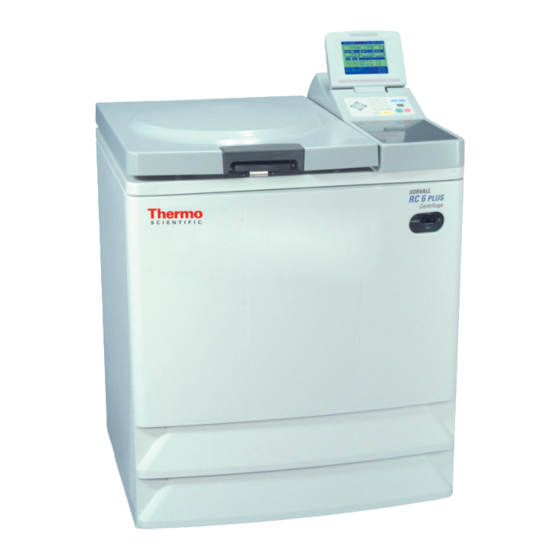
DESCRIPTION This manual provides you with the information you will need to operate and maintain your Thermo Scientific RC-6 PLUS Superspeed Centrifuge. If you encounter any problem concerning either operation or maintenance that is not covered in the manual, please contact Thermo Fisher Scientific for assistance. - Page 12 The RC-6 PLUS accepts the Thermo Scientific Superspeed rotors listed in the Rotor Information Table in the Appendix. Refer to Figure 1-1 to identify the parts of the RC-6 PLUS.
- Page 13 INTRODUCTION & DESCRIPTION Centrifuge Description Figure 1-1. Centrifuge Parts Location and Identification Thermo Fisher Scientific RC-6 PLUS...
-
Page 14: Centrifuge Specification
INTRODUCTION & DESCRIPTION Centrifuge Specifications Centrifuge Specifications Table 1-1. Centrifuge Specifications Run Speed Speed Selection Range (rpm) 300 to 22,000 Speed Control Accuracy ±25 rpm Maximum Relative Centrifugal Force 52,200 x g (F20MICRO) Run Temperature Temperature Selection Range -20°C to 40°C Temperature Control Range 2°C to 40°C Temperature Control Accuracy... -
Page 15: Centrifugeaccessories
INTRODUCTION & DESCRIPTION Centrifuge Accessories After the centrifuge system has reached equilibrium. Ambient air temperature at the centrifuge air inlets must be between 2°C to 40°C with maximum relative humidity of 80% at 31°C, linearly de- creasing to 50% at 40°C. If the ambient air temperature is above 25°C, the centrifuge may not main- tain low temperatures at high speeds, therefore, avoid areas near heat sources (for example, direct sunlight, heating pipes and radiators). - Page 16 INTRODUCTION & DESCRIPTION Centrifuge Accessories RC-6 PLUS Thermo Fisher Scientific...
-
Page 17: Chapter 2 Installation
INSTALLATION Chapter 2 Installation or relocation of your centrifuge must be done by an authorized Thermo Fisher Scientific representative. Contact Thermo Fisher Scientific or your local representative of Thermo Fisher Scientific products. After you receive your centrifuge, inspect it for damage before using it. The RC-6 PLUS centrifuge must be installed in a location that meets all of the electrical, location, and environment requirements that are specified below and on the following pages. - Page 18 INSTALLATION Identify the Installation Site When choosing an installation site for the RC-6 PLUS Centrifuge, consider its dimensions, weight and noise level: Table 2-1. Dimensions Width: 752 mm Depth: 835m (including rear duct assembly) Depth: 685m (without rear duct assembly) Height: 1112 mm Weight 350 kg...
-
Page 19: Levelling The Centrifuge
INSTALLATION Leveling the Centrifuge Figure 2-1. Clearances for the Centrifuge CAUTION Leave adequate space for airflow around the centrifuge and make sure no vents are blocked. Blocking the airflow entering and/or exiting the centrifuge can result in reduced performance, overheating and possible centrifuge damage. -
Page 20: Electronical Requirements
INSTALLATION Electrical Requirements Figure 2-2. Leveling the Centrifuge Electrical Requirements CAUTION The centrifuge can be damaged if it is connected to the wrong voltage, or if it is connected to a line voltage that varies more than plus/minus 10% of its nominal value. - Page 21 INSTALLATION Electrical Requirements To connect to a different voltage, the centrifuge must be rewired and its plug may also have to be replaced. Contact Thermo Fisher Scientific or your local representative of Thermo Fisher Scientific products. For connection to a different outlet, the power cord may also need to be replaced.
-
Page 22: Relocation
INSTALLATION Relocation Relocation CAUTION Remove the rotor from the rotor chamber before relocating the centrifuge. CAUTION Be careful not to tip over the unit when moving on uneven or slanted floors. Installation or relocation of your centrifuge must be done by an authorized authorized Thermo Fisher Scientific representative. -
Page 23: Controls, Displays, & Indicators
CONTROLS, DISPLAYS Chapter 3 & INDICATORS This chapter describes the RC-6 PLUS centrifuge controls, displays, and indicators and includes their locations and functions. Controls, The RC-6 PLUS control keyboard is used to select desired run parameters. Displays, & During a run, digital displays indicate set and actual run conditions, such as estimated sample temperature, rotor speed, remaining run time or accumulated Indicators integral value. -
Page 24: Chapter 3 Controls, Displays & Indicators
CONTROLS, DISPLAYS & INDICATORS Operation Panel Figure 3-2. Zoom Screen RC-6 PLUS Thermo Fisher Scientific... - Page 25 CONTROLS, DISPLAYS & INDICATORS Operation Panel Table 3-1. Name Display Panel Function (refer to Figure 3-1) Field display Displays the following run conditions. For SPEED, TIME and TEMP displays, the upper line shows the actual run state and the lower line shows the set value.
- Page 26 CONTROLS, DISPLAYS & INDICATORS Operation Panel Table 3-1. Name Display Panel Function (refer to Figure 3-1) FUNCTION • PROG Used to save run conditions for field programmed operation. • RCF Used to display and set RCF value. ω • T Used to display and set for integrator operation.
-
Page 27: Power Switch
CONTROLS, DISPLAYS & INDICATORS POWER Switch Table 3-2. Name Key Function (refer to Figure 3-3) Cursor keys (1) Makes the RUN SCREEN ready-to-enter state. (2) Moves the cursor on the screen. 1. Moves the cursor upward ( 2. Moves the cursor left ( ). 3. -
Page 28: Diagnostic Indicators Safety Device
CONTROLS, DISPLAYS & INDICATORS Diagnostic Indicators Safety Device Do not position the centrifuge so that the movement of the POWER switch may become difficult. Figure 3-4. POWER switch Diagnostic Indicators Safety Device Protection of Rotor Chamber The rotor chamber allows the rotor to rotate at high speeds. A steel protector is provided around the chamber for the operator’s safety in case of any rotor mishap during centrifugation. -
Page 29: Chapter 4 Operation
OPERATION Chapter 4 This chapter provides step-by-step instructions on how to set the centrifuge power ON, open the chamber door, and perform a run in the normal mode. It also describes how to precool the rotor. Read and observe the Important Safety Information supplied on page iii at the front of this manual. -
Page 30: Basic Operation
OPERATION Basic Operation Basic Operation WARNING 1. Failure to load and install the rotor in accordance with the instructions in the rotor operating guide could result in damage to the centrifuge. The rotor cover must be on and locked in place and the rotor must be locked on to the drive spindle. - Page 31 OPERATION Basic Operation RUN Screen CAUTION 1. Do not tilt the display panel forcibly or, mechanical components can be damaged. 2. Do not press the function keys with a sharp-pointed object such as a ballpoint pen. 3. If an abnormal sound is heard during the operation, stop the operation immediately and contact Thermo Fisher Scientific or your local representative of Thermo Fisher Scientific products.
- Page 32 OPERATION Basic Operation Cursor Keys A cursor appears and blinks on the entry line of a run condition display by pressing a cursor key as shown in Figure 4-2. The entry line state varies depending on the presence of cursor as shown below.
- Page 33 OPERATION Basic Operation Table 4-1. Step Key Operation Screen Display and Notices Press the ROTOR key on the KEY BOARD. Enter the rotor number to be used with the ten-key numerical pad and press the NTER key. (The screen turns to the next page by pressing the cursor key.) The screen returns to the RUN SCREEN.
- Page 34 OPERATION Basic Operation Table 4-2. Set Run Conditions Item Speed (SPEED) Run Time (TIME) Example set value 20,000 rpm 2 hours, 30 minutes Press a cursor to turn the display The display turns to The display turns to to ready-to-enter state. readyto-enter state.
- Page 35 OPERATION Basic Operation Note Keep the chamber door closed after the rotor has been removed to inhibit the formation of condensation on the chamber walls. To repeat the run with the same speed, time and temperature parameters, install the rotor, close the chamber door, press START and then press ENTER. Table 4-3.
-
Page 36: Normal Operating Procedure
OPERATION Normal Operating Procedure Normal Operating This section describes the procedure for normal operation. Procedure Note Before following the procedure, read the rotor instruction manual carefully and make sure that you have selected the appropriate type of tube for the sample, and that the amount of sample in the tubes is correct. - Page 37 OPERATION Normal Operating Procedure Figure 4-3. RUN Mode Indicator Acceleration Rate and The acceleration and deceleration rates can be adjusted for a wide range of Deceleration Rate use. The figure below shows how a rotor accelerates and decelerates in compliance with a code number selected from 1 through 9. Table 4-5.
- Page 38 OPERATION Normal Operating Procedure Figure 4-4. Acceleration and Deceleration Rates FUNCTION Field Figure 4-5. Function Field The RC-6 Plus Superspeed centrifuge has many add-on features such as programmed operation and centrifugal force values displaying and setting. These features are displayed and selected on the FUNCTION field. PROG : You can save run conditions in memory for later use in repeated operation.
-
Page 39: Saving And Changing Run Condition
OPERATION Saving and Changing Run Conditions Saving and To save or change run conditions in memory, use the following procedure. Changing Run Conditions Table 4-6. Change Run Conditions in Memory Step Key operation Screen display and notices Move the cursor to The FUNCTION field turns to the PROGRAM PROG and press field. - Page 40 OPERATION Saving and Changing Run Conditions Table 4-6. Change Run Conditions in Memory Step Key operation Screen display and notices When other The run conditions are saved at MEMORY No. 2. conditions are saved, selecr the desired memory No. (.g.: at MEMORY NO.2) And enter run conditions as...
- Page 41 OPERATION Saving and Changing Run Conditions Table 4-6. Change Run Conditions in Memory Step Key operation Screen display and notices After saving run *The PROGRAM field appears by the first press conditions, press of the ESC key. the ESC key twice. *The FUNCTION field appears by the second press of the ESC key.
-
Page 42: Step-Mode Operation
OPERATION Step-mode Operation Table 4-7. Recalled Run Conditions Step Key operation Screen display and notices Move the cursor to The FUNCTION field turns to the PROGRAM PROG and press field. the ENTER key. Press the ENTER The screen turns to the MEMORY No. LIST key when the screen. - Page 43 OPERATION Step-mode Operation the run conditions (e.g., speed, run time, rotor temperature, etc.) for each step during a step-mode run. Save step-mode run conditions at the MEMORY Nos. 31 - 33 (41 - 43 or 51- 53) in accordance with "3-3-1 Programmed Operation (1)".
-
Page 44: Rtc (Real Time Control) Operation
OPERATION RTC (Real Time Control) Operation Note (2) Use the MEMORY Nos. 32 and 33 (42 and 43 or 52 and 53) for the step-mode operation with two steps. RTC (Real Time The RC-6 Plus Superspeed Centrifuge can be programmed to perform automatic centrifugation by setting the incorporated time clock to start and end Control) Operation centrifugation at the desired time in advance. - Page 45 OPERATION RTC (Real Time Control) Operation Procedure for RTC Operation Step Key operation Screen display and notices Set the run • Set the run conditio ns referring to Setting Run conditions. Conditions. • not select HOLD but enter a For time setting, do numeric value.
- Page 46 OPERATION RTC (Real Time Control) Operation Step Key operation Screen display and notices Enter the desired date and time (month, day, hour and minutes) using the cursor keys and the ten-key numeri- cal pad. Press the ENTER key. • The range for "hour" setting is from 0 to 23 (24-hour display).
- Page 47 OPERATION RTC (Real Time Control) Operation Step Key operation Screen display and notices Check the RTC • Perform operation according Operating setting on the Procedure. RUN SCREEN and press the • Note that the run time setting cannot be changed START key.
- Page 48 OPERATION Displaying and Setting RCF 3. Clear the RTC setting and then reset the run time if it is necessary to change the run time setting after setting the RTC operation. 4. Recall the saved run conditions and enter the RTC setting when performing the programmed operation (including the step-mode operation) and the RTC operation in combination.
-
Page 49: Displaying And Setting Rdcf
OPERATION Displaying and Setting w2T Table 4-10. Use of RCF Displaying and Setting Step Key operation Screen display and notices Move the cursor to PROG and press the ENTER key. The FUNCTION indicator turns to the RCF display. RCF(Upper line). Displays the actual RCF computed for the motor speed and selected rotor. - Page 50 OPERATION Displaying and Setting w2T Step Key operation Screen display and notices Set the speed in See Basic Operation. the Run Screen. The FUNCTION indicator turns to the ω 1. Use cursor T set screen. keys to move cursor to ω on the RUN SCREEN.
-
Page 51: Emergency Recovery From Power Failure
OPERATION Emergency Recovery from Power Failure When the displayed ω Treaches the set value of ω Note T, the machine decelerates and stops. During deceleration,ω T is integrated and its result is displayed until a stop. T is selectable between 0.01E03 and 9.99E17. The w T operation is canceled by changing the set time or changing the operation mode to the programmed operation mode. - Page 52 OPERATION Emergency Recovery from Power Failure Rotation of Rotor The rotating rotor coasts free and finally stops if a power failure occurs during operation. When the power is restored, the centrifuge automatically re-accelerates the rotor if the rotor is still rotating at 250 rpm or higher, or decelerates the rotor if the rotor is rotating under 250 rpm.
- Page 53 OPERATION Emergency Recovery from Power Failure 2. Turn off the POWER switch of the centrifuge and the distribution board of your centrifuge room. 3. Remove the two screws from the lower portion of the front cover. Remove the front cover by pulling the lower portion of the front cover forward and downward.
-
Page 54: Features On Menu Screen
OPERATION Features on Menu Screen WARNING Never attempt to slow or stop the rotor by hand. 6. Take out the rotor and remove the adhesive tape from the door lock solenoids. Insert the hooks into the square holes and put the front cover on the support, then secure the front cover with the screws in the reverse order of removal. - Page 55 OPERATION Features on Menu Screen Table 4-12. Features on Menu Screen Screen Utilities You can customize the unit’s time setting, screen contrast level, and run screen. Changing RUN SCREEN 1 = NORMAL RUN SCREEN is displayed. ZOOM: display automatically turns to ZOOM screen when 20 seconds have passed after reaching the set speed.
-
Page 56: Lockout System Function
OPERATION Lockout system function (optional) Table 4-12. Features on Menu Screen Precool The temperature in the chamber is controlled at about 15 degrees centigrade if the door is closed and Precool is selected. (The temperature in the chamber may not hold at 15 degrees centigrade ambient temperature or the temperature of... - Page 57 OPERATION Lockout system function (optional) Table 4-13. Lockout System Step Key operation Screen display and notices When using the lockout system, turn on the main power switch. Then the initial screen of the lockout system is displayed. Input your (registered user) own ID code (4digits) and press the ENTER key.
- Page 58 OPERATION Lockout system function (optional) Step Key operation Screen display and notices After using the centrifuge, log off the lockout system according to the following procedure. (The lockout system can also be logged off by turning off the main power switch.) lockout system is not available next time...
-
Page 59: Chapter 5 Care And Maintenance
CARE AND Chapter 5 MAINTENANCE This section describes routine maintenance activities to ensure your centrifuge remains in good operating condition. We also recommend that you have the centrifuge serviced at least once a year, more frequently if you use it heavily. Contact Thermo Fisher Scienific or your local representative of Thermo Fisher Scienifi products. -
Page 60: Rotor Chamber
CARE AND MAINTENANCE Rotor Chamber CAUTION Do not operate the instrument in any way other than specified in this manual. If you encounter any problem with the instrument, call an authorized Thermo Fisher Scientific Representative. Chlorides (for example, bleach solutions) are extremely harmuful to aluminum alloys and can cause stress corrosion cracking. - Page 61 CARE AND MAINTENANCE Rotor Chamber CAUTION Do not pour any solution such as water, detergent or disinfectant directly into the rotor chamber. Otherwise, the bearings of the drive unit may become corroded or deteriorate. To defrost the chamber: 1. Install a rotor and close the chamber door. 2.
-
Page 62: Tapered Drive Shaft (Drive Spindle)
CARE AND MAINTENANCE Tapered Drive Shaft (Drive Spindle) Tapered Drive Shaft (Drive Spindle) CAUTION Clean the inside of the centrifuge drive spindle hole the surface of the drive spindle once a month. If the drive hole or the drive shaft is stained or any foreign matter is adhered, the rotor may be improperly installed and come off during operation This part is very important because the rotor is mounted on and is driven by the... -
Page 63: Replacement Parts
CARE AND MAINTENANCE Replacement Parts Replacement Parts To order replacement parts, contact Thermo Fisher Scientific or your local representative of Thermo Fisher Scientific products. Be sure to provide the part number, the part name, and the quantity of parts you need, as well as the model and serial number of the Superspeed centrifuge you are using. - Page 64 CARE AND MAINTENANCE Service Decontamination Policy prepared with the name and nature of the sample so the official Thermo Fisher Scientific representative can decide whether to authorize the rotor's return to a Thermo Fisher Scientific facility. Do not leave a loaded rotor locked inside a centrifuge that requires servicing. If, with a loaded rotor installed in the chamber, a centrifuge malfunction makes it so that the chamber door will not open by normal means, follow the Emergency Recovery from Power Failure found in your centrifuge operating instructions...
- Page 65 CARE AND MAINTENANCE Service Decontamination Policy 3. With the RMA Number clearly marked on the outside of packaging, send the items to the address obtained from your Thermo Fisher Scientific representative. Note United States federal regulations require that parts and instruments must be decontaminated before being transported.
- Page 66 CARE AND MAINTENANCE Service Decontamination Policy RC-6 PLUS Thermo Fisher Scientific...
-
Page 67: Chapter 6 Troubleshooting
TROUBLESHOOTING Chapter 6 The RC-6 PLUS Superspeed centrifuge has a self-diagnosis capability that identifies and reports a problem that occurs when the instrument is starting up or in operation, and that affects the operation of the instrument. Alarm Messages When a problem occurs that affects instrument operation, the centrifuge beeps and displays an alarm message, in order to report the occurrence of the problem. - Page 68 TROUBLESHOOTING Step Key operation Screen display and notices Select "ALARM INFORMATION" by pressing the following keys. ALARM INFORMATION screen appears. Corresponding alarm information displayed. * Press the ESC key two times to return to the RUN SCREEN. Corrective Actions In response to the displayed alarm message, take the appropriate actions as described below to identify the cause of the problem, then press the CE key to clear the alarm.
- Page 69 TROUBLESHOOTING Table 6-2. Corrective Actions Alarm Cause Corrective action message DOOR OPEN START key is pressed with the door Close the door and start operation. opened, or the door handle is released If the door handle is released, lock it again while the rotor is rotating.
- Page 70 TROUBLESHOOTING Table 6-3. User Corrected Problems Symptom Cause Corrective Action Run conditions cannot be The rotor is still rotating. recall set or recalled. conditions when the rotor stops completely. Recalled run conditions The battery to back up the Set the run conditions again are changed.
-
Page 71: Rotor Information Table
APPENDIX Appendix 7 Rotor Information Table CAUTION Read the rotor instruction manual thoroughly before use. Mount the rotor cover securely. Be sure to tighten the rotor locking knob after mounting the rotor on the drive spindle. Table 7-1. Rotor Information Table Rotor Code # Max. - Page 72 APPENDIX Warranty Table 7-1. Rotor Information Table Rotor Code # Max. Max. Max. Radius Radius Speed Factor Compart Max. Min. (rpm) ment (cm) (cm) Mass (g) F14S-6X250 14,000 29,994 1,676 13.70 3.74 SLC-3000 10,000 17,604 3,394 15.76 4.12 SA-512 18,500 44,040 11.52 6.37...
- Page 73 APPENDIX Warranty Thermo Fisher Scientific reserves the right to change, alter, modify, or improve any instruments without any obligation whatsoever to make corresponding changes to any instrument previously sold or shipped. Extended Warranties are conditional on the instrument being correctly maintained by authorized Service Representatives on an annual basis.
- Page 74 APPENDIX Warranty RC-6 PLUS Thermo Fisher Scientific...
- Page 75 DECONTAMINATION INFORMATION CERTIFICATE Complete and attach to equipment BEFORE servicing (instructions on reverse) PLEASE PRINT DECONTAMINATION CERTIFIED BY ______________________________________ TITLE/POSITION ____________________________________ PHONE ___________________FAX _____________________ DEPARTMENT ______________________________________ INSTITUTION ______________________________ ADDRESS __________________________________________________ CITY_______________________________________STATE _________________________ZIP ________________________ INSTRUMENT ____________________________________________________ SERIAL NUMBER ______________________ ROTOR _________________________________________________________ SERIAL NUMBER ______________________ PART __________________________________________________________ PART NUMBER _______________________ HAZARDOUS CONTAMINANTS(S)____________________________________ DECONTAMINATION DATE ______________ DECONTAMINATION METHOD(S) _________________________________________________________________________...
- Page 76 INSTRUCTIONS When an instrument that has been used with radioactive, If an instrument is received at our Service facilities and, in our pathogenic, or otherwise hazardous materials requires opinion, poses a radioactive or biological hazard, the sender servicing by Thermo personnel either at the customer’s will be contacted for instructions as to disposition of the laboratory or at Thermo facilities, the following procedure equipment.
- Page 78 CHINA INDIA JAPAN Tel.: +86 21 68 65 45 88 Tel.: +91 22 55 42 94 94 Tel.: +81 454 53 92 20 Tel.: +86 10 58 50 35 88 OTHER ASIA PACIFIC COUNTRIES Tel.: +852 28 85 46 13 AUSTRIA BELGIUM FINLAND...
Need help?
Do you have a question about the RC 6 Plus and is the answer not in the manual?
Questions and answers