Table of Contents
Advertisement
Quick Links
Download this manual
See also:
User Manual
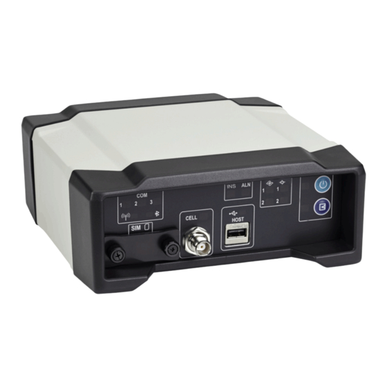
ProPak6 - Front
This guide provides the basic information needed to set up and use a NovAtel
USER MANUALS
For detailed information on the installation and operation of the NovAtel receiver, download the
User Manual
(OM-20000148).
For detailed information on the logs and commands used to configure the NovAtel receiver, download the
OEM6 Family Firmware Reference Manual
If a SPAN
OEM6 Quick Start Guide
Sales@NovAtel.com to obtain SPAN software functionality for your receiver.
BOX CONTENTS
The following is provided with the ProPak6 (NovAtel part number):
•
ProPak6 receiver with built in Wi-Fi, Bluetooth
•
12 VDC power adapter (CLA) with slow blow fuse (01017663)
•
Null modem serial cable (01017658)
•
DB9 male extension cable (01018520)
•
I/O DB9 male interface cable (01018519)
•
Mounting bracket and screws (70023096, quantity 2 and 28523058, quantity 4)
Additional Equipment Required
The additional equipment listed below is required for a typical setup (refer to
20000148) for further details).
•
A standard 12 VDC power outlet or 9-36 VDC power supply capable of at least 14 W
•
A Windows computer with a RS-232 DB-9, Ethernet or USB port
•
A quality GNSS antenna, such as NovAtel's 700 or ANT series
•
An antenna cable with a TNC male connector at the receiver end
such as NovAtel's GPS-C016 model
•
A cellular antenna and SIM card (model dependant)
(OM-20000129).
®
GNSS+INS capable ProPak6 was purchased, download the
(GM-14915112). To purchase SPAN firmware, contact
ProPak6™
QUICK START GUIDE
GM-14915125
®
, USB 2.0 and 4 GB of onboard memory
Rev 3
August 2014
®
ProPak6.
ProPak6
SPAN on
ProPak6 User Manual
ProPak6 - Back
(OM-
1
Advertisement
Table of Contents

Related Manuals for Novatel ProPak6


Summary of Contents for Novatel ProPak6
-
Page 1: Quick Start Guide
For detailed information on the installation and operation of the NovAtel receiver, download the ProPak6 User Manual (OM-20000148). For detailed information on the logs and commands used to configure the NovAtel receiver, download the OEM6 Family Firmware Reference Manual (OM-20000129). ... - Page 2 PROPAK6 MOUNTING Use brackets and screws provided with the ProPak6 to facilitate mounting the receiver to a surface. Prior to connecting any cables and installing the ProPak6 in a fixed position, attach the supplied mounting brackets to the ProPak6. ...
- Page 3 GETTING TO KNOW THE PROPAK6 Refer to ProPak6 User Manual (OM-20000148) for details on all ProPak6 connectors, labelling and LEDs as well as detailed installation and operation instructions. Refer to the OEM6 Firmware Reference Manual - OM-20000129 for details regarding any ProPak6 logs or commands.
- Page 4 Table 2: ProPak6 - Front Label Definitions Button/ Connector/LED Label LED States Description Type Power button and status LED Solid red = Valid power Power Press and hold the power button a Solid green = Operational mode minimum of 3 s and maximum of 10 s...
- Page 5 (25 mm x 15 mm) SETTING UP A PROPAK6 Complete the following steps to connect and power the ProPak6. Be sure to mount the antenna to a secure, stable structure with an unobstructed view of the sky. 1. Connect GNSS antennas to the ANT1 port and ANT2 port (if equipped) found on the back of the ProPak6 and connect an external oscillator (if equipped) to the adjacent OSC port.
- Page 6 NOVATEL CONNECT™ Once installed, NovAtel Connect provides a graphical interface to establish communication, control and monitor the operation of your NovAtel receiver. Go to www.novatel.com/support/firmware-software-and-manuals/firmware-software-updates/ novatel-connect/ to access and download the latest version of NovAtel Connect PC Utilities. Establishing a New Receiver Connection The first time a serial port is opened to communicate with the receiver, complete the following: 1.
-
Page 7: Post Processing
The Solution Status is also indicated as computed in the Position window. Entering Commands Commands can be sent to the receiver using the NovAtel Connect Console window (found under View menu if not displayed by default). Enter commands in the text box at the bottom of the Console window. -
Page 8: Data Logging
(OM-20000148) for details on logging. ONBOARD MEMORY The ProPak6 contains 4 GB of memory for onboard data storage. Data can be logged to internal memory and downloaded for post-processing. The ProPak6 onboard memory can be accessed using FTP. Refer to ProPak6 User Manual (OM-20000148) for details. -
Page 9: Wifi Configuration
Manual-OM20000129 for any log and command details. WI-FI CONFIGURATION When the ProPak6 Wi-Fi radio is enabled, it can be configured to act as a Access Point (AP) or Client. Wi-Fi AP (default) 1. Connect the ProPak6 to a computer using one of the communication ports and turn power on. - Page 10 7. Issue the SAVECONFIG command to save the configuration Non-Volatile Memory (NVM). 8. On a Wi-Fi Client, scan for a ProPak6 and connect to it. When prompted, enter a password and press The default password is the Product Serial Number (PSN) located on the bottom of the ProPak6.
- Page 11 Wi-Fi Client 1. Connect the ProPak6 to a computer using one of the communication ports and turn power on. Scanning 2. Log WIFICLISCANRESULTS ONCHANGED to display a list of the scan results. 3. Log WIFICLISTATUS ONCHANGED to monitor the connection status.
- Page 12 Screws should be torqued to 4-6 inch-pound. Failure to properly secure SIM cover will violate ProPak6 IP67 ingress rating. 4. Ensure a cellular antenna is connected to the ProPak6 and turn the ProPak6 power on. 5. Log CELLULARSTATUS ONCHANGED to display the modem and cellular connection status.
-
Page 13: Airplane Mode
AIRPLANE MODE Enabling Airplane Mode turns off any Wi-Fi, Bluetooth or cellular radios in the ProPak6. Airplane Mode is disabled by default (radio on). If Airplane mode is enabled and then disabled, all radios automatically return to their last state (on or off) however, any connections made before airplane mode was enabled are not restored. -
Page 14: Enabling L- Band
Receivers must be powered and tracking an L-Band satellite prior to activating a subscription service. For more information on L-Band positioning: • Refer to a NovAtel Application Note: APN-061 NovAtel CORRECT with TerraStar, APN- 062 NovAtel CORRECT with Veripos or APN-051 Positioning Modes of Operation (service dependent) available from www.novatel.com/support/search/items/Application%20Note •... - Page 15 GNSS positions. In most cases, a data link between the base station and rover station (two NovAtel receivers) is required in order to receive corrections. It is also possible to receive and use RTK corrections from established networks.
-
Page 16: Questions Or Comments
1-800-NOVATEL (U.S. and Canada) or 403-295-4900 China 0086-21-54452990-8011 Europe 44-1993-848-736 SE Asia and Australia 61-400-883-601 QUESTIONS OR COMMENTS For questions or comments regarding the ProPak6, please contact NovAtel using one of these methods: Email: support@novatel.com Web: www.novatel.com Phone: 1-800-NOVATEL (U.S. and Canada)
Need help?
Do you have a question about the ProPak6 and is the answer not in the manual?
Questions and answers