Table of Contents
Advertisement
SIMATIC
FM 353
Stepper Drive Positioning
Module
Manual
6ES7 353-1AH01-8BG0
04/2007 Edition
Preface, Contents
Product Overview
Basic Principles of Positioning
Installing and Removing
Wiring
Defining Parameters
Programming the Technological
Functions
Starting up
Human-machine Interface
Description of Functions
Writing Traversing Programs
Troubleshooting
Appendices
Technical Specifications
User Data Block (AW−DB)
List of Abbreviations
Index
1
2
3
4
5
6
7
8
9
10
11
A
B
C
Advertisement
Table of Contents

Related Manuals for Siemens SIMATIC FM 353


Summary of Contents for Siemens SIMATIC FM 353
- Page 1 Preface, Contents Product Overview Basic Principles of Positioning SIMATIC Installing and Removing FM 353 Wiring Stepper Drive Positioning Module Defining Parameters Programming the Technological Functions Manual Starting up Human-machine Interface Description of Functions Writing Traversing Programs Troubleshooting Appendices Technical Specifications User Data Block (AW−DB) List of Abbreviations Index...
- Page 2 Trademarks All names marked with the copyright notice R are registered trademarks of SIEMENS AG. Other names in this publication might be trademarks whose use by a third party for his own purposes may violate the rights of the registered holder.
-
Page 3: Installing And Removing
Preface Information This manual contains all information about the FM 353 module: S Hardware and functions S Parameterization S Human-machine interface S S7 blocks S Safe design Information blocks in this manual The following information blocks describe the purpose and application of this manual: S Product overview of the module (Chapter 1) This section explains the purpose and possible applications of the module. - Page 4 These users operate the FM 353. The operator accordingly deals only with the control of positioning tasks. Note The PROFINET functionality described in the present manual (in the current version) is only available on request. Please get in touch with your Siemens contact partner. FM 353 Stepper Drive Positioning Module 6ES7 353-1AH01-8BG0...
- Page 5 Recycling and disposal For recycling in an environmentally compatible manner and for the disposal of your old SIMATIC in line with prsent state of technology, please contact your appropri- ate Siemens contact partner: http://www.automation.siemens.com/partner Technical support If you have any technical question, please do no hesitate to contact our hotline:...
- Page 6 Preface Further support We are offering courses to help you familiarize yourself with the operation of the SIMATIC S7 programmable controller system. Please contact your regional or the central training center in D-90027 Nürnberg, Germany under tel. +49 911-89 53 202. FM 353 Stepper Drive Positioning Module 6ES7 353-1AH01-8BG0...
-
Page 7: Table Of Contents
Table of Contents Product Overview ............The FM 353 in the S7-300 programmable controller . - Page 8 Table of Contents Standard function blocks of the “FMSTSV_L” block library ... . 6.3.1 Overview of the “FMSTSV_L” function block library ....6.3.2 The POS_INIT (FC 0) block −...
- Page 9 Table of Contents Operating modes ..........9-14 9.2.1 Jogging...
- Page 10 Table of Contents Troubleshooting ............11-1 11.1 Error classes and module responses...
-
Page 11: Product Overview
Product Overview Chapter overview Section Section Header Page The FM 353 in the S7-300 programmable controller Module description Overview of the module functions What can the FM 353 do? The FM 353 is a microprocessor-controlled positioning module for actuating a step- per motor. -
Page 12: The Fm 353 In The S7-300 Programmable Controller
Product Overview Where can the FM 353 be used? The FM 353 can be used for both simple positioning and complex traversing pro- files demanding superior dynamic response, accuracy and speed. It is also suitable for positioning tasks in machinery with high clock-pulse rates. Typical uses for the positioning module might include: S Transfer lines S Assembly lines... - Page 13 Product Overview Multi-rack configurations A SIMATIC S7-300 CPU may run up to four racks with as many as eight bus sta- tions each (see Figure 1-1). Programming device Operator panel Backplane Rack 3 dig./anal. dig./anal. dig./anal. dig./anal. dig./anal. dig./anal. 24 V Rack 2 dig./anal.
- Page 14 Product Overview System overview A complete positioning controller using the FM 353 consists of a variety of individ- ual components, which are shown in Figure 1-2. Operator panel (OP) Your programming device (PG) (e.g. OP 07) Configuration package DIN rail SIMATIC S7-300 SM SM FM 353...
- Page 15 Product Overview Components The most important components and their functions are listed in Table 1-1. Table 1-1 Components of a positioning controller Component Function DIN rail ... the module mounting rack for the S7-300. FM 353 ... the positioning module. It is controlled by the S7-300 CPU..
- Page 16 Product Overview System overview of data handling The following figure gives you an overview of the data storage concept. FM 353 Module data Loading buffer Module data Diagnostic data P bus User program, including blocks User DBx Diagnostic/ process Online data interrupt Operating system −...
-
Page 17: Module Description
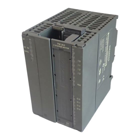
Product Overview Module description View of the FM 353 Figure 1-4 shows the FM 353 module, its interfaces and front-panel elements (in- cluding fault and status displays). DIN rail Module name plate: FM 353 FM STEPPER MOTOR Bus connector SIMATIC port Front door Labeling plate (flips open) -
Page 18: Led Indicators
Product Overview Ports A description of the ports is provided in Table 1-2. Table 1-2 Ports Ports Description Bus connector − Back connector to continue the S7 LAN from module to module SIMATIC port Drive port 15-pin male sub-D connector (X2) to connect the drive unit I/O port 20-pin male front connector (X1) to connect the load power supply and for digital input and output wiring... -
Page 19: Overview Of Module Functions
Product Overview Type plate of the FM 353 Figure 1-5 describes all the information contained in the type plate of the FM 353. SIEMENS SVP JM123456 Made in Germany Product status Marks and approvals Module identifier Order number Fig. 1-5... - Page 20 Product Overview Mode control The operating mode is specified to the FM 353 by way of the user program. The FM 353 has the following modes available: S Jogging S Open-loop control S Reference point approach S Incremental mode, relative S MDI-Manual Data Input) S Automatic S Automatic single block...
- Page 21 Product Overview Settings and functions not dependent on operating mode Special functions can be activated by specific settings in the user program, in addi- tion to the mode (e.g., inprocess measurement). Software limit switches The operating range (specified by software limit switches) is automatically moni- tored after synchronization is recorded.
- Page 22 Product Overview FM 353 Stepper Drive Positioning Module 1-12 6ES7 353-1AH01-8BG0...
-
Page 23: Basic Principles Of Positioning
Basic Principles of Positioning What is positioning? Positioning means moving a load to a defined position within a defined time, taking all influencing forces and torques into account. Position A Position B F = driving force Dx = distance to be traversed s = path Fig. - Page 24 Basic Principles of Positioning Structure of a positioning circuit Figure 2-2 show the structure of a position control circuit with FM 353 and stepper motor. Power grid EMERG. STOP FM 353 Drive port Safety de- Power section vice Parameterize Movement Motor Mechanical transmis- sion elements...
- Page 25 Basic Principles of Positioning Mechanical transmission elements These include not only the axis, but also gear trains and clutch systems. Peripherals All other additional equipment is covered by the term peripherals. Peripherals mainly include: S Limit switches to limit the positioning range (safety devices). S A programming device (PG) and the “Parameterize FM 353”...
- Page 26 Basic Principles of Positioning FM 353 Stepper Drive Positioning Module 6ES7 353-1AH01-8BG0...
-
Page 27: Installing And Removing
Installing and Removing Chapter Overview Section Section Header Page Installing the FM 353 Removing the FM 353 Replacing modules Overview The FM 353 is intended for installation as an I/O module in the SIMATIC S7-300 programmable logic controller. Important safety rules There are important rules which you must follow when integrating an FM 353 in the S7-300 PLC in a plant or system. - Page 28 Installing and Removing What you should know about the mechanical layout The FM 353 can be mounted in any of the eight available slots (slot nos.: 4...11) for I/O modules on the mounting rail. In configuring the mechanical layout of your controller, you should note the follow- ing rules: 1.
-
Page 29: Installing The Fm
Installing and Removing Installing the FM 353 Rules No particular protective measures (EGB Guidelines) are necessary for the installa- tion of the FM 353. Warning Install the FM 353 only after all power to the S7-300 has been turned OFF. Tools required A 4.5 mm (.18 inch) screwdriver. -
Page 30: Removing The Fm 353
Installing and Removing Removing the FM 353 Rules No particular protective measures (EGB Guidelines) are necessary for the removal of the FM 353. Warning Remove the FM 353 only after all power to the S7-300 has been turned OFF. Tools required A 4.5 mm (.18 inch) screwdriver. -
Page 31: Replacing Modules
Installing and Removing Replacing modules Overview If a defective FM 353 has to be replaced, and no programming device/PC is avail- able for parameterization, or the module is to be replaced while the system is switched on, please note the following start-up requirements (CPU, FM): S An SDB w 1 000 should be generated in order to complete the startup (for stor- ing the parameter data);... - Page 32 Installing and Removing FM 353 Stepper Drive Positioning Module 6ES7 353-1AH01-8BG0...
-
Page 33: Wiring
Wiring Chapter Overview Section Section Header Page Wiring an FM 353 Description of the drive interface Connecting the drive unit 4-11 Description of the I/O interface 4-12 Wiring up the front connector 4-18 Safety rules In order to ensure the safe operation of your plant, you should introduce the follow- ing additional measures, and adjust them appropriately to your system’s condi- tions: S An EMERGENCY STOP concept meeting appropriate safety regulations (e.g. -
Page 34: Wiring An Fm 353
When wiring the FM 353 you must observe the relevant VDE guidelines. Wiring an FM 353 Summary Figure 4-1 shows how the individual components of the positioning controller with FM 353 are linked together. Front connector SIEMENS SIMATIC S7-300 External 24 V power supply FM 353 MPI connecting cable Dig. - Page 35 Wiring Note The device is designed for operation with safety extra−low voltage (SELV). This means that only safety extra−low voltages (SELV) complying with IEC950/EN60950/VDE0805 may be connected to the power supply terminals. The power unit for supplying the device must comply with NEC Class 2 as de- scribed by the National Electrical Code(r) (ANSI/NFPA 70).
-
Page 36: Description Of The Drive Interface
Wiring Description of the drive interface Connector for the drive unit Stepper motor power sections which have at least one clock generator and direc- tion input with 5 V signal level can be connected to the 15-pin sub-D X2 connector of the FM 353. - Page 37 Wiring Signal names PULSE, PULSE_NC Lock signal, true and negated DIR, DIR_N Direction signal, true and negated ENABLE, ENABLE_N Enable signal, true and negated PWM/BOOST, PWM_N/BOOST_N Current control, true and negated READY1_N Ready message Signal ground Signal type Output Input Note The active level of each signal can be defined in MD37 (see Section 5.3.1, 9.7).
- Page 38 Wiring Output signals Clock, directional and enable signals are provided. In addition, an additional signal can be parameterized for current generation. S PULSE The clock pulses control the motor. The motor executes one increment in re- sponse to each rising pulse edge. This means that the number of pulses which are output determines the angle of rotation, i.e.
- Page 39 Wiring Signal parameters of the outputs All output signals are output by way of differential-signal line drivers in compliance with Standard RS422. To ensure optimum noise immunity, the power section should feature differential signal receivers or optical coupler inputs to permit bal- anced signal transfer.
- Page 40 Wiring Signal wiring (output signals) Figure 4-3 shows various ways to wire the signals. Balanced transfer with RS422-compliant differential input FM 353 Power section l v 35 m − Balanced transfer with optical coupler input l v 35 m Unbalanced transfer with optical coupler input l v 10 m Unbalanced transfer with voltage input l v 10 m...
- Page 41 Wiring Input signal READY1_N This input is non-isolated and works with a 5V level. A floating output (switching contact or optical coupler) may be connected. The FM 353 interprets this input as a Ready message from the power section. An alternative connection option is available by way of peripherals connector X1 (see Section 4.4).
- Page 42 Wiring Signal connection for the “READY1_N” input The illustration shows you different signal connection options for the “READY1_N” input. Actuation of the “READY1_N” input by contact FM 353 Power section l v 35 m Actuation of the “READY1_N” input by optical coupler l v 35 m Actuation of the “READY_1”...
-
Page 43: Connecting The Drive Unit
Wiring Connecting the drive unit To connect the connecting cables Please note: Note Use only shielded twisted pairs for lines. The shielding must be connected to the metallic or metallized connector jacket on the controller side. To protect the analog setpoint signal against low-frequency interference, we recommend that you not ground the shielding on the drive-unit side. -
Page 44: Description Of The I/O Interface
Wiring Identification of the connecting cable The connecting cable is a cable set for one axis with an analog interface. The ter- minals are identified for SIMODRIVE drive units. Order No.: 6FX2 002-3AC01-1VV0 The connecting cable is available in a variety of lengths. see Catalog NC Z , Order No.: E86060-K4490-A001-AV. - Page 45 Wiring Connector pinout Connector identifier: Connector type: 20-pin S7 front connector for single-wire terminal Table 4-5 Pinout of the X1 connector Name Type Name Type open not assigned not assigned not assigned open not assigned open not assigned RM_P RM_N Signal names DI1 −...
- Page 46 Wiring 4 digital inputs (DI1...4) All inputs have equal priority. Switching functions are allocated to an input number by way of machine data; input polarity is selected in the same way (starting and shutdown slopes). These fast inputs are PLC-compatible (24 V current-sourcing). Switches or con- tactless sensors (2-wire or 3-wire sensors) can be connected.
- Page 47 Wiring Table 4-7 Electrical parameters, “Ready message” input Parameters Value Unit Comment 1 signal, voltage range 15 − 30 1 signal, power consumption 2 − 6 0 signal, voltage range −3 − 5 or input open Signal delay 0 → 1 µs Signal delay 1 →...
- Page 48 Wiring Power from the drive unit Figure 4-8 shows examples of how to power the standby signal from the drive unit. Actuation, current-sourcing Power section FM 353 RM_P RM_N Actuation, current-sinking RM_P RM_N Fig. 4-8 Actuation of the input controller message, power supply from the drive unit 4 digital outputs (DQ1...4) All outputs have equal priority.
- Page 49 Wiring Table 4-8 Electrical parameters of digital outputs Supply voltage 24 V DC (allowable range: 20.4 − 28.8 V) Electrical isolation Output voltage 0 signal: Residual current max. 2 mA 1 signal: (Power supply −3 V) Output current on signal “1” at ambient temperature of 40_C −...
-
Page 50: Wiring Up The Front Connector
Wiring Wiring up the front connector Wiring up the front connector Figure 4-9 shows how to lay the lines to the front connector, and how to relieve strain on the lines with the terminal element. ENCODER X3 DC5V DIAG − DC24V FM 353 Labeling on inside of front door... - Page 51 Wiring Note To provide optimum immunity to interference, shielded cables should be used to connect touch probes or sensors. Tools required A 3.5 mm (.13 inches) screwdriver or power screwdriver. Procedure for wiring the front connector To wire the terminal strip: 1.
- Page 52 Wiring Shielding terminal element To provide a shielding end lead for shielded cables, this element can be inserted in the DIN rail. It can accept up to eight shielding terminals (KLBÜ line from Weidmüller). Order No.: Terminal element: 6ES7 390-5AA00-0AA0 Shielding terminal: 6ES7 390-5CA00-7AA0 see Catalog NC 60.1, Order No.
-
Page 53: Defining Parameters
Defining Parameters Chapter Overview Section Section Header Page Installing “Parameterize FM 353” Getting started with “Parameterize FM 353” Parameter data Parameterization with “Parameterize FM 353” 5-25 Storing the parameter data in SDB w 1 000 5-26 FM 353 Stepper Drive Positioning Module 6ES7 353-1AH01-8BG0... - Page 54 Defining Parameters Overview This chapter gives you an overview of how to define the parameters of the FM 353 with the “Parameterize FM 353” tool. S7-300 FM 353 P bus Data blocks (DB) User DB-MD data block Online (editing in the DB-SM Target system menu K bus...
- Page 55 Defining Parameters Installing “Parameterize FM 353” Prerequisites One of the following operating systems must be installed on the programming de- vice (PG/PC): S Windows 2000 S Windows 2003 Server S Windows XP You need the STEP 7 program (V5.3 +SP2 or higher) For online operation, make sure that your programming device (PG) / PC is connected to the S7-300 CPU (see Figure 4-1).
-
Page 56: Getting Started With "Parameterize Fm
Defining Parameters Getting started with “Parameterize FM 353” Prerequisites You have installed the software on your programming device/PC, as described in Section 5.1. Configuration Before you can configure your system, you must create a project in which to save the parameters. You will find further information on how to configure modules in your user manual Standard Software for S7 and M7, STEP 7. - Page 57 Defining Parameters 7. By clicking on the tabs in this FM 353 window (General, Addresses and Basic Parameters), you can − Assign a name − Change the address of the FM as well as any input parameters for the POS_INIT block (see Section 6.3.2) −...
- Page 58 Defining Parameters You can use the mouse to change the size of the window for entering the parame- ter data and the size of the overview display. Proceed as follows: 1. Position the mouse pointer on the top border of the window, so that it changes into an arrow.
-
Page 59: Parameter Data
Defining Parameters Parameter data What can I parameterize? You can parameterize the following data storage areas: S Machine data (MD) S Increment sizes (SM) S Tool offset data (TO) S Traversing programs (NC) S User data (user data blocks) This data is stored in data blocks (DBs) within the numerical range 1001 to 1239 (not including user data). - Page 60 Defining Parameters Table 5-1 Data blocks, continued Data block Significance DB-SM Increments (DB No. = 1230) User memory requirements = 468 bytes Increments serve in the “Relative incremental” operating mode as user- definable relative path distances for individual positioning. You can de- fine from 1 to 100 increment sizes (see Section 5.3.2).
-
Page 61: Machine Data
Defining Parameters Data block structure Table 5-2 gives a rough picture of data block structure. Table 5-2 Data block structure Addresses/ Contents Comment Offset DB header System information, not relevant for user 0 and above User data area / structure header Information for labeling of data block within the system 24 and above... - Page 62 Defining Parameters Entering values In “Parameterize FM 353” select the menu File > New > Machine Data to call up the following display. Fig. 5-4 Entering values for machine data Enter the machine data in the tab windows. You can also enter your values in a table by selecting View > Table form. When creating the MD DBs you must follow the instructions in Chapter 7 “Starting up the FM 353”.
- Page 63 Defining Parameters Machine data list All machine data of the FM 353 are listed in Table 5-4. Notes to the machine data list: K are configuration data; see Section 9.3.3 E are settable machine data for alignment (start-up optimization) and technology, see Section 9.3.3 The units of measurement refer to the value representation in the machine data Table 5-4...
- Page 64 Defining Parameters Table 5-4 Machine data list, continued Default Data type/ Designation Value/Meaning values Unit/Comments Sec. not assigned 18 K Type of reference-point 0 = direction + current-sourcing DWORD 9.2.3 approach pattern zero or zero pulse Code identifies external to right of RPS position for syn- (reference-point ap- chronization point...
- Page 65 Defining Parameters Table 5-4 Machine data list, continued Default Data type/ Designation Value/Meaning values Unit/Comments Sec. 32 K M-function during positioning: DWORD 10.3 output type serial output of up 1 = time-controlled to 3 M functions in 2 = acknowledgment-controlled NC block before positioning: 3 = time-controlled...
- Page 66 Defining Parameters Table 5-4 Machine data list, continued Default Data type/ Designation Value/Meaning values Unit/Comments Sec. 37 K Special control signals 0 = Servo enable active BITFIELD32 2 = Servo ready active 3 = Servo ready inverted 4 = Servo ready via connector X2 (if Bits 24--27 active) 7 = Time override active 8 = Pulse output inverted...
- Page 67 Defining Parameters Table 5-4 Machine data list, continued Default Data type/ Designation Value/Meaning values Unit/Comments Sec. 48 K Boost duration, absolute 1 − 1,000,000 9.7.2 49 K Boost duration, relative 1 − 100 DWORD [%] 9.7.2 50 K Phase current travel 51 K Phase current idle 52 E Speed for backlash DWORD...
- Page 68 Defining Parameters Dependencies With certain combinations of machine data, restrictions in the value range arise for non-processing of the machine data. These dependencies are verified on acceptance of the MD DB or individual ma- chine data, and an error message is output in the event of a violation. Some checks are performed on the basis of internally calculated reference variables.
- Page 69 Defining Parameters MD11, MD12, MD13 check → results in MWFAKTOR (see above) −14 Permissible measured value factor range: < MWFAKTOR < 2 MD21, MD22 check SEAKT MD8 Permissible software limit switches − MD21 = −10 , MD22 = +10 MD21 ≥ −VFBABS MD21 ≥...
- Page 70 Defining Parameters MD42 check Permissible acceleration: MD41 / 200 ≤ MD42 ≤ MD39 MD43 check MD43 Permissible acceleration ≠ 0 MD41 / 200 ≤ MD43 ≤ MD39 MD44 check MD44 Permissible acceleration ≠ 0 MD41 / 200 ≤ MD44 ≤ MD39 MD45 check MD45 Permissible acceleration...
- Page 71 Defining Parameters “Working range of frequency generator” You can use the following diagram to check that the combination of parameters selected in machine data MD39 to MD45 lie within the working range of the fre- quency generator (white area). 10 20 40 1 000 10 000 [Hz]...
-
Page 72: Increments
Defining Parameters 5.3.2 Increments DB structure Table 5-5 gives you a general view of the structure of the “Increments” data block (DB-SM). Table 5-5 DB structure − increments Byte Variable type Value Significance of the variables Comment DB header WORD Rack slot Module address WORD... -
Page 73: Tool Offset Data
Defining Parameters 5.3.3 Tool offset data DB structure Table 5-6 gives you a general view of the structure of the “tool offset data” data block (DB-WK). Table 5-6 DB structure − tool offset data Byte Variable type Value Significance of the variables Comment DB header WORD... - Page 74 Defining Parameters Input of values Values are input in the tool offset data menu of the “Parameterize FM 353” para- meterization tool. If the additive wear value is changed online, the FM calculates the new wear pa- rameter as an absolute value and the additive tool wear is reset to 0. Fig.
-
Page 75: Traversing Programs
Defining Parameters 5.3.4 Traversing programs DB structure Table 5-7 gives you a general view of the structure of the “traversing programs” data block (DB-NC). Table 5-7 DB structure − traversing programs Byte Variable type Value Significance of the variables Comment DB header WORD Rack slot... - Page 76 Defining Parameters Input of traversing programs An empty window is provided for the input of NC traversing programs. Here you can input your traversing program as follows: Fig. 5-8 Entry for traversing programs 1. % Program number Program name The “%” can be input only in the first line. This input is mandatory. The DB num- ber is formed from the program number.
-
Page 77: Parameterization With "Parameterize Fm
Defining Parameters Parameterization with “Parameterize FM 353” Entering the values You have a variety of options for entering your parameterization data. 1. User data You can input values or select texts in a table. Select input fields with the cursor and enter the values. -
Page 78: Storing The Parameter Data In Sdb
Defining Parameters Storing the parameter data in SDB w 1 000 Overview The FM 353 stores its parameter data internally. In order to ensure that the parameter data are available if a fault develops on the FM 353 and no programming device/PC is at hand, the data can be stored in a system data block (SDB w 1 000). - Page 79 Defining Parameters Creating the SDB Prerequisite: Online connection with the FM 353 Select menu File > Create SDB If no DB-MD exists on the FM 353 → Abort An associated SDB w 1 000 exists for the FM 353 in the No associated SDB exists S7 project.
- Page 80 Defining Parameters Loading the SDB in the CPU When you have created the SDB, you must load the “system data” of the project into the CPU. There are two ways of proceeding: Method 1 Select the online window in the SIMATIC Manager (the online and offline win- dows must be open) Copy the system data from the offline project in CPU\S7-Program\Blocks\Sys- tem data into the online project (drag with the mouse or select Copy/Paste).
-
Page 81: Programming The Technological Functions
Programming the Technological Functions Chapter Overview Section Section Header Page Programming fundamentals Putting the FM 353 into operation with the parameter initialization tool Standard function blocks of the “FMSTSV_L” block library Standard function blocks of the “FM353_354” block library 6-28 (also for PROFINET, upon request) Interrupts 6-44... - Page 82 Programming the Technological Functions General remarks The purpose of the function description of the blocks and of the interface is to illus- trate the communication between the CPU and the FM 353 in the SIMATIC S7 pro- grammable controller. The programmable blocks and the AW-DB (which is the in- terface to the FM 353) make it possible for you to write your user program to suit your particular application.
- Page 83 Programming the Technological Functions Prerequisites The following prerequisites must be fulfilled for the development of your user pro- gram if you want to control the FM 353: S You must have installed the software on the PG/PC as per Section 5.1. The block libraries containing the basic functions are stored in the following directories by default: −...
-
Page 84: Communication Between The Cpu And The Fm 353
Programming the Technological Functions Programming fundamentals Overview In this chapter you will find information on the following: S Communication between the CPU and the FM 353, Section 6.1.1, p. 6-4 S Structure of a user program, Section 6.1.2, p. 6-5 S Distributed use of OB 86, Section 6.1.3, p. -
Page 85: Structure Of A User Program
Programming the Technological Functions 6.1.2 Structure of a user program The diagram below provides an overview of the structure of the user program (AWP). OB 100 and OB 86 (in distributed configurations) Call of POS_INIT The CPU goes to STOP when an error occurs during start-up. Parameter entry OB 1 (or other cyclic levels) User DB... -
Page 86: Distributed Configuration, Ob 86
Programming the Technological Functions Information on testing the user program When testing the user program with “Set breakpoint”, please note that it is not al- ways possible to resume the program scan with the FM 353 after the breakpoint has been reached (for technical reasons). For example, movements activated by the user program cannot be halted when the user program has reached the breakpoint. -
Page 87: Procedure For Writing The User Program (Awp)
Programming the Technological Functions 6.1.5 Procedure for writing the user program (AWP) The sample projects “zDt13_02_FM353_EX” included in the configuring package (for the blocks of the “FMSTSV_L” library) and “zDt13_03_FM353_EX” (for blocks of the “FM353_354” library) will help you when creating your user program and can be used as a template. -
Page 88: Putting The Fm 353 Into Operation With The Parameter Initialization Tool
Programming the Technological Functions Putting the FM 353 into operation with the parameter initialization tool To put the FM 353 into operation with the parameter initialization tool “Parameter- ize FM 353”, the CPU must be at “STOP”. It can also be at “RUN”, for example if you want to automate part of your plant or connect the drives, in which case the control/checkback signals “Switch P bus interface to start-up”... -
Page 89: Overview Of The "Fmstsv_L" Function Block Library
Programming the Technological Functions 6.3.1 Overview of the “FMSTSV_L” function block library You can use the blocks of the “FMSTSV_L” block library as follows: S Central configuration of the FM S Distributed configuration of the FM via PROFIBUS DP The table below provides an overview of the functions (FC), data blocks (DB) and organization blocks (OB) required for communication and control of the FM 353. -
Page 90: The Pos_Init (Fc 0) Block − Initialization
Programming the Technological Functions 6.3.2 The POS_INIT (FC 0) block − Initialization Function Use the POS_INIT block to initialize specific areas of your AW-DB. Call options The POS_INIT block must be called once in the start-up OB 100 and in OB 86 for ”distributed configuration”. - Page 91 Programming the Technological Functions Function description The POS_INIT block carries out the following actions: 1. Entry of addressing values in user DB AW-DB, If parameter LADDR ≠ 0 Module address 2. Deletion of the following structures in user DB AW-DB: −...
-
Page 92: The Pos_Ctrl (Fc 1) Block − Data Exchange
Programming the Technological Functions 6.3.3 The POS_CTRL (FC 1) block − Data exchange Function The POS_CTRL block is the basic block for controlling the FM 353. With the POS_CTRL block, you can: S process read and write requests S control the operatign modes (control and checkback signals) The POS_CTRL block performs the following actions: 1. - Page 93 Programming the Technological Functions Parameters The Table below lists the parameters for this block. Name Data Param. Description Type Type DB_NO Data block number RET_VAL INT Return value Parameter types: I = input parameter, Q = output parameter Return values The function returns the following values: RET_VAL Description...
- Page 94 Programming the Technological Functions S Job requests Data interchange with the module that goes beyond control and checkback sig- nals is handled using job requests. Simultaneously pending Write or Read re- quests, however, can only be executed in succession, whereby one Read and one Write request are processed in one call.
- Page 95 Programming the Technological Functions S Job request status You can read the status of the job request in return value RET_VAL and in the “Write/read job in progress” signals in user data block AW-DB (DBX68.0 and DBX68.2). You can evaluate the status of an individual job request by evaluat- ing the Initiate, Ready and Error signals for that job request.
- Page 96 Programming the Technological Functions Error evaluation Communication errors or data interpretation errors on the FM are flagged in the Binary Result (BR = 0) and by RET_VAL < 0; see job request status. Possible errors are: S Data transfer error (communication is not completed) during a transfer with SFC 58/59 “WR_REC / RD_REC”.
- Page 97 Programming the Technological Functions Processing write requests Before Write requests can be processed, the data area associated with the Write request must first be initialized with the relevant values and the appropriate operat- ing mode. A Write request is initiated by setting the relevant job request number. The following abbreviations are used in the Table below to indicate the adjacent operating mode: Operating mode: T...
- Page 98 Programming the Technological Functions Processing read requests A Read request is initiated by setting the relevant job request number. The relevant operating mode must be activated. The following Read requests are available: Operating Mode Read Data A/AE System Data Request Sect.
- Page 99 Programming the Technological Functions Table 6-3 Control/checkback signals German English AW-DB Description R− DIR_M DBX15.2 Negative direction DIR_P DBX15.3 Positive direction ACK_MF DBX15.4 Acknowledge M function READ_EN DBX15.5 Read Enable SKIP_BLK DBX15.6 Skip block DRV_EN DBX15.7 Drive enable MODE_IN DBB16 Operating mode Code Control...
- Page 100 Programming the Technological Functions The checkback signals “Process in progress” and “Position reached. Stop” are not reported back to the user program until the FM has detected and processed the Start signal (v 2 FM cycles). When calling the POS_CTRL block and the relevant control/checkback signals, the subsequent signals are generated so that starting of the procedure can be de- tected earlier than would otherwise be the case.
- Page 101 Programming the Technological Functions The functions which can be activated in the FM using single settings or single com- mands are listed below. Single Settings Single Commands Servo enable Activate machine data On-the-fly measuring Delete distance to go Rotational speed monitoring Automatic block return Parking axis Automatic block advance...
- Page 102 Programming the Technological Functions 6.3.4 The POS DIAG (FC 2) block − Read diagnostic interrupt data In the event of a fatal error, the FM 353 generates a diagnostic interrupt (OB 82 must be embedded in the user program and the interrupt parameterization of the FM 353 must be activated) and provides the relevant information to the local data area.
- Page 103 Programming the Technological Functions Error evaluation Errors are flagged in the Binary Result (BR = 0) and by RET_VAL < 0. Possible errors are as follows: Data transfer error during transfers with SFC 51 “RDSYSST”. The error is made available in the user DB AW-DB, DBW96 (see Error List, Section 6.8). Diagnostic data The prerequisite for the generation of a diagnostic interrupt is activation of the in- terrupt with the aid of the appropriate parameters (see Section 5.2).
- Page 104 Programming the Technological Functions Table 6-5 Diagnostic information, continued Data Message User DB Description Format 10 x When the DBB74 FM pos. ID (74H) byte POS DIAG bl POS_DIAG block is DBB75 Length of the diagnostic information (16) called, the informa- called, the informa- tion (incl.
- Page 105 Programming the Technological Functions 6.3.5 The POS MSRM (FC 3) block − Read measured values Function Use the POS_MSRM block to read the measured values from the AW-DB user data block. For information on process interrupts, please see Section 6.5. For information on measured values 9.3.10.
-
Page 106: Interface, User Data Blocks (Aw-Dbs)
Programming the Technological Functions Function description The function works together with an AW-DB user data block. When the function is called, the DB number is forwarded in the DB_NO parameter. Reading of the measured value is started by setting the IN_MSR parameter to TRUE. - Page 107 Programming the Technological Functions Creating the AW-DB Proceed as follows: 1. Open your project and select SIMATIC xxx > CPUxxx > S7 Program > Blocks. 2. The data block (for example DB 1) is generated under STEP 7 with the menu command Insert >...
-
Page 108: Overview Of The "Fm353_354" Block Library
Programming the Technological Functions Standard function blocks of the “FM353_354” block li- brary (also for PROFINET, upon request) Overview The present chapter provides the following information: S Overview of the “FM353_354” block library, Section 6.4.1, p. 6-28 S POS_INIT (FC 0) − Initializing the user data block (AW-DB), Section 6.4.2, p. - Page 109 Programming the Technological Functions The table below provides an overview of the functions (FC), function blocks (FB), data blocks (DB) and organization blocks (OB) required for communication and control of the FM 353. Table 6-6 Standard function blocks of the “FM353_354” block library (overview) Block Block Name Description/Function...
-
Page 110: The Pos_Init (Fc 0) Block − Initialization
Programming the Technological Functions 6.4.2 The POS_INIT (FC 0) block − Initialization Block description See Section 6.3.2. 6.4.3 The POS_CTRL (FC 1) block − Data exchange Function The POS_CTRL block is the basic block for controlling the FM 353. With the POS_CTRL block, you can: S process read and write requests S control the operating modes (control and checkback signals) The POS_CTRL block performs the following actions:... - Page 111 Programming the Technological Functions Call options The POS_CTRL block requires an instance data block (DB) when called. The DB IFFM_ICTRL (DB1) is part of the “FM353_354” library and at the same time inclu- des the user interface. For more information, please refer to Section 6.4.6. You must call the POS_CTRL block cyclically (e.g.
- Page 112 Programming the Technological Functions Function description The block operates with an AW-DB user data block. The DB number is determined when calling the FB using a transferred instance DB. S Start-up POS_CTRL acknowledges start-up of the module. During this time, the RETVAL parameter and the “Write/Read job in progress”...
- Page 113 Programming the Technological Functions As soon as a Write request is detected (also on a signal change in the case of single functions), it is serviced immediately upon completion of the transfer cur- rently in progress, if any. Be sure that signals for single commands are not set cyclically, as this could prevent other job requests from being serviced (priority).
- Page 114 Programming the Technological Functions Processing status Signal Description Write not possible = TRUE; Write request cannot be processed in this cycle because: (AW-DB, DBX68.1) The axis is not initialized Test mode is enabled No operating mode is active The selected operating mode has not yet been set In these cases, you can leave the Write request pending or you can cancel it.
- Page 115 Programming the Technological Functions Error evaluation Communication errors or data interpretation errors on the FM are flagged in the Binary Result (BR = 0) and by instance variable RETVAL < 0; see job request sta- tus. Possible errors are: S Data transfer error (communication is not completed) during a transfer with SFC 58/59 “RDREC / WRREC”.
- Page 116 Programming the Technological Functions Processing write requests Before Write requests can be processed, the data area associated with the Write request must first be initialized with the relevant values and the appropriate operat- ing mode. A Write request is initiated by setting the relevant job request number. The following abbreviations are used in the Table below to indicate the adjacent operating mode: Operating mode: T...
- Page 117 Programming the Technological Functions Processing read requests A Read request is initiated by setting the relevant job request number. The relevant operating mode must be activated. The following Read requests are available: Operating Mode Read Data A/AE System Data Request Sect.
- Page 118 Programming the Technological Functions Table 6-8 Control/checkback signals German English AW-DB Description DIR_P DBX15.3 Positive direction ACK_MF DBX15.4 Acknowledge M function READ_EN DBX15.5 Read Enable SKIP_BLK DBX15.6 Skip block DRV_EN DBX15.7 Drive enable MODE_IN DBB16 Operating mode Code Control Approach to reference point Incremental mode, relative Automatic Automatic single block...
- Page 119 Programming the Technological Functions The checkback signals “Process in progress” and “Position reached. Stop” are not reported back to the user program until the FM has detected and processed the Start signal (v 2 FM cycles). When calling the POS_CTRL block and the relevant control/checkback signals, the subsequent signals are generated so that starting of the procedure can be de- tected earlier than would otherwise be the case.
- Page 120 Programming the Technological Functions The functions which can be activated in the FM using single settings or single com- mands are listed below. Single Settings Single Commands Servo enable Activate machine data On-the-fly measuring Delete distance to go Rotational speed monitoring Automatic block return Parking axis Automatic block advance...
- Page 121 Programming the Technological Functions 6.4.4 The POS DIAG (FC 2) block − Read diagnostic interrupt data Block description See Section 6.3.4. 6.4.5 The POS MSRM (FC 3) block − Read measured values Function Use the POS_MSRM block to read the measured values into the AW-DB user data block.
-
Page 122: Interface, User Dbs (Aw-Dbs)
Programming the Technological Functions Parameters The Table below lists the parameters for the POS_MSRM block. Name Data Param. Description type type DB_NO Data block number RETVAL −1 IN_MSR BOOL Start Read Parameter types: I = input parameter, Q = output parameter, I/Q = throughput parameter (initiation parameter) Function description The function works together with an AW-DB user data block. - Page 123 Programming the Technological Functions Note If the POS_CTRL block is called for several channels/axes, a new instance DB of the POS_CTRL block is to created for each individual channel/axis. To assign the datza to the relevant channel/axis, this instance is always to be transferred when calling the block.
-
Page 124: Interrupts
Programming the Technological Functions Interrupts Interrupt processing The FM 353 can generate process interrupts and diagnostic interrupts. You can process these interrupts only in an interrupt OB (OB 40 or OB 82). If an interrupt is generated without the associated OB having been loaded, the CPU goes to STOP (refer to the manual entitled Programming with STEP 7). - Page 125 Programming the Technological Functions Evaluating a diagnostic interrupt Following a diagnostic interrupt, the diagnostic information is made available in the local data area of OB 82 for quick analysis. Call the POS_DIAG block to ascertain the exact cause of error (see Section 6.3.4). FM 353 Stepper Drive Positioning Module 6-45 6ES7 353-1AH01-8BG0...
-
Page 126: User Data Block (Aw-Db)
Programming the Technological Functions User data block (AW-DB) Overview The Table below describes the structure of the user data block. Table 6-11 User data block (AW-DB) AW-DB FM 353 Byte Bit 7 Bit 6 Bit 5 Bit 4 Bit 3 Bit 2 Bit 1 Bit 0... - Page 127 Programming the Technological Functions Table 6-11 User data block (AW-DB), continued AW-DB FM 353 Byte Bit 7 Bit 6 Bit 5 Bit 4 Bit 3 Bit 2 Bit 1 Bit 0 Actual position DBD28 (with firmware version V3.7.6 and higher in conjunction with the blocks of the “FM353_354” library DBW32 Reserved Initiation signals...
- Page 128 Programming the Technological Functions Table 6-11 User data block (AW-DB), continued AW-DB FM 353 Byte Bit 7 Bit 6 Bit 5 Bit 4 Bit 3 Bit 2 Bit 1 Bit 0 Ready signals Ready signals Status/checkback signals from POS_CTRL Parking Rotation In-process Controller...
- Page 129 Programming the Technological Functions Table 6-11 User data block (AW-DB), continued AW-DB FM 353 Byte Bit 7 Bit 6 Bit 5 Bit 4 Bit 3 Bit 2 Bit 1 Bit 0 Error signals Error signals Error messages from POS_CTRL Parking Rotation In-process Controller...
- Page 130 Programming the Technological Functions Table 6-11 User data block (AW-DB), continued AW-DB FM 353 Byte Bit 7 Bit 6 Bit 5 Bit 4 Bit 3 Bit 2 Bit 1 Bit 0 Diagnostic data for the FM, read out with POS_DIAG Ext.
- Page 131 Programming the Technological Functions Table 6-11 User data block (AW-DB), continued AW-DB FM 353 Byte Bit 7 Bit 6 Bit 5 Bit 4 Bit 3 Bit 2 Bit 1 Bit 0 Error code following flagging of “Data error” DBB94 Error number (DS163) − Detail event class DBB95 Error number (DS163) −...
- Page 132 Programming the Technological Functions Table 6-11 User data block (AW-DB), continued AW-DB FM 353 Byte Bit 7 Bit 6 Bit 5 Bit 4 Bit 3 Bit 2 Bit 1 Bit 0 MDI block DBB176 Reserved DBB177 G function group Position/ Position/ DBB178 DBB178...
- Page 133 Programming the Technological Functions Table 6-11 User data block (AW-DB), continued AW-DB FM 353 Byte Bit 7 Bit 6 Bit 5 Bit 4 Bit 3 Bit 2 Bit 1 Bit 0 DBB227 G function no. of group 2 DBB228 Reserved DBB229 DBD230 Value for position/dwell (data type DINT)
- Page 134 Programming the Technological Functions Table 6-11 User data block (AW-DB), continued AW-DB FM 353 Byte Bit 7 Bit 6 Bit 5 Bit 4 Bit 3 Bit 2 Bit 1 Bit 0 Active NC block DBB342 Program number DBB343 Block number G function group No.
- Page 135 Programming the Technological Functions Table 6-11 User data block (AW-DB), continued AW-DB FM 353 Byte Bit 7 Bit 6 Bit 5 Bit 4 Bit 3 Bit 2 Bit 1 Bit 0 Application data DBD382 Application data 1 (data type: DINT) DBD386 Application data 2 (data type: DINT) DBD390...
- Page 136 Programming the Technological Functions Table 6-11 User data block (AW-DB), continued AW-DB FM 353 Byte Bit 7 Bit 6 Bit 5 Bit 4 Bit 3 Bit 2 Bit 1 Bit 0 DBB450 Array, structure/data type according to data, to be read as per bytes 1 to 4 of this structure (e.g.
-
Page 137: Sample Applications
Programming the Technological Functions Sample applications Overview This chapter provides information on the following: S Basic example for setting the operating mode S Example 1: Moving axes in “JOG mode” and “Approach to reference point mode” S Example 2: Traversing an MD block S Example 3: “Automatic”... - Page 138 Programming the Technological Functions Note In the examples, the axes do not traverse in simulation mode! Because “DBEX” is a retentive DB, it is initialized in the start/restart routine (OB 100). If this is not required, simply delete the initialization section of OB 100 (net- work “DBEX Initialization”).
- Page 139 Programming the Technological Functions Example 1 Open the example project. The block used for this example is FC 101. The signals are in “DBEX”. The signals relevant for Example 1 only are in structure “EX1”. The Drive Enable and the Controller Enable for the axis are set in “DBEX” (OB 100: DRV_EN = TRUE, SERVO_EN = TRUE) and are transferred to the interface (AW_DB) in Example 1.
- Page 140 Programming the Technological Functions Example 2 Open the example project. The block used for this example is FC 102. The signals are in “DBEX”. The signals relevant for Example 2 only are in structure “EX2”. The Drive Enable and the Controller Enable for the axis are set in “DBEX” (OB 100: DRV_EN = TRUE, SERVO_EN = TRUE), and are transferred to the interface (AW-DB) in Example 2.
- Page 141 Programming the Technological Functions Example 3 Open the example project. The block used for this example is FC 103. The signals are in “DBEX”. The signals relevant for Example 3 only are in structure “EX3”. The program to be selected in the Example has the program number “10”. This program number is entered in Example 3.
- Page 142 Programming the Technological Functions Example 4 Open the example project. The block used for this example is FC 104. Note: If you call the example 4 in OB 1, then please do not call the examples 1 to 3 at the same time; otherwise, data would be overwritten. In this example, the HMI interface signals for the data range from DBB 498 through DBB 515 are transferred to the interface area for the control signals, e.g.
- Page 143 Programming the Technological Functions Structure of “DBEX” (DB 100) DATA_BLOCK “DBEX” STRUCT // *** General signals *** ERR_CODE_INIT : INT; // Error code for POS_INIT ERR_CODE_CTRL : INT; // Error code for POS_CTRL ERR_CODE_DIAG : INT; // Error code for POS_DIAG OVERRIDE : BYTE;...
-
Page 144: Error List, System Messages (Cpu)
Programming the Technological Functions Error list, system messages (CPU) The Table below lists some of the errors which occur during data transfer with the internal SFC/SFBs (RET_VAL in SFCs 51, 58 and 59 and status messages (bytes 2 and 3), SFB 52/53, system messages) (see Reference Manual System Software for S7-300/400;... - Page 145 Programming the Technological Functions Table 6-12 Error list, continued Error Code (AW-DB, DBW66) Description Description 80C4 32964 −32572 Communication error; repeat the job. 80C5 32965 −32571 Distributed I/O not available 80C7 32966 −32570 Job aborted due to restart (warm restart) or cold restart of DP master 8522 34082 −31454...
-
Page 146: Technical Specifications
Programming the Technological Functions Technical specifications Memory allocation The Table below provides an overview of the memory allocation for the blocks and the user data block (AW-DB). All values are rounded. Table 6-13 Memory requirements for the blocks and user data block Block Block in bytes MC7 code in... - Page 147 Programming the Technological Functions Table 6-15 Processing times for the blocks, continued Block Transfer Cycle 1 Cycle 2 Cycle 3 POS_DIAG Read process and diagnostic data 3.2 ms − − POS_MSRM Read measured values 3.6 ms Processing times for the blocks when used in a distributed configuration PROFIBUS DP), taking the following example The specified times are rounded.
- Page 148 Programming the Technological Functions FM 353 Stepper Drive Positioning Module 6-68 6ES7 353-1AH01-8BG0...
-
Page 149: Starting Up
Starting up Chapter Overview Section Section Header Page Installation and wiring Initial values for testing and optimization Testing and optimization Overview This Chapter introduces you to the user interface for testing and start-up, and pro- vides check lists for starting up the positioning module. The checklists will help you: S Check all steps until the module is running. -
Page 150: Installation And Wiring
Starting up Installation and wiring Installation information You can find information about how to install your module: S In Chapter 3 of this manual S In the manual S7-300 Programmable Controller, Hardware and Installation Wiring information You can find information about how to wire your module: S In Chapter 4 of this manual S In the manual S7-300 Programmable Controller, Hardware and Installation Checklist... -
Page 151: Initial Values For Testing And Optimization
Starting up Initial values for testing and optimization Parameterization information You can find information about parameterization: S In Chapter 5 of this manual S In the on-line help in “Parameterize FM 353” Overview The following overview display appears in the “Parameterize FM 353” tool: Fig. - Page 152 Starting up Checklist Despite the “acceptance” testing just mentioned, the ultimate responsibility for the accuracy of all machine data lies with the module user. So it is highly advisable to perform startup using the following checklist. Table 7-2 Parameterization checklist Step Check What to do:...
- Page 153 Starting up Table 7-2 Parameterization checklist, continued Step Check What to do: Tool offset data Tool offset data is needed only for the “Automatic” mode and is not nec- essary for the startup described here. Generally, it is not needed until you start up the user program on the S7-300 CPU.
- Page 154 Starting up Table 7-3 Initial contents of machine data, continued MD (E) Value Explanation 0.2@v 20% of the maximum speed is the recommended initial value 0.1@v 10% of the maximum speed is the recommended initial value 30/31 Backlash compensation inactive Start/Stop frequency from operating characteristic curve, see Section 7.3.2 Frequency value for acceleration switchover from operating...
-
Page 155: Testing And Optimization
Starting up Testing and optimization Testing and optimization information Once you have installed, wired and parameterized the unit, you can test and opti- mize your FM 353 positioning module. Testing and optimization can be performed with the aid of the testing and start-up interface with or without the user program. You can also test individual modes and their traversing programs, and view and debug them during execution. - Page 156 Starting up 1 − Error field 2 − Status field (e.g. actual values, checkback signals) 3 − Field for mode-specific inputs 4 − Field for input of values/settings/commands and start/stop for movement The abbreviations for the checkback signals are described in Table 9-2. Fig.
- Page 157 Starting up Note Select a mode Turn simulation on (if you want an operating case) Servo enable Drive enable Override 1 − 100% You can operate the “R+” and “R-” buttons in the “jogging” mode as follows: 1. Select “R+” or “R-” with the mouse 2.
- Page 158 Starting up You can also call up the following screens: The following display appears when you select Test > Alarms: Fig. 7-3 Troubleshooting The following display appears when you select Test > Service data: Fig. 7-4 Service data FM 353 Stepper Drive Positioning Module 7-10 6ES7 353-1AH01-8BG0...
- Page 159 Starting up The following display appears when you select Test > Trace: Fig. 7-5 Trace FM 353 Stepper Drive Positioning Module 7-11 6ES7 353-1AH01-8BG0...
- Page 160 Starting up Checklist When starting up the machine axis, it is important to perform the following steps in the indicated sequence. Steps 1 to 5 are always necessary; the rest are optional, depending on your own application. Table 7-4 Checklist - startup of machine axis Step Check What to do?
-
Page 161: Activating The Machine Data
Starting up 7.3.1 Activating the machine data Overview The checkback signal PARA notifies you that a DB-MD has been retained. This machine data is automatically activated at power-up. The module’s positioning functions are ready to operate. If no DB-MD is present as yet on the FM 353 when the control is switched on, the module can only communicate by way of the MPI interface. -
Page 162: Evaluating The Characteristics Of The Stepper Motor
Starting up 7.3.2 Evaluating the characteristics of the stepper motor Overview Basically, the stepper motor is a highly dynamic drive motor which is capable of following setpoint assignments more or less free of following error. It is also capa- ble of handling the transition between idle time and movement (and back) by way of the start/stop frequency at an extremely high rate of acceleration. - Page 163 Starting up Determining the machine data: Torque increase from boost [Nm] Maximum permissible Torque drop from PWM operating moment Start/Stop SS (J = 0) Load [1/min] 100 f1 f0 1 000 10 000 f [Hz] [kg@cm e.g. 500 increments/revolution Load n [1/min] 1 200 Fig.
- Page 164 Starting up MD39: Start/stop frequency f 1. Enter J into J diagram (e.g. 3 kg@cm 4. Enter M in M diagram (e.g. 0.6 Nm) Load Load 2. Determine f0 (e.g. 150 Hz) from intersection 5. Determine f1 (e.g. 130 Hz) from intersection with J curve with SS curve 3.
- Page 165 Starting up Notes Notes regarding special boundary conditions: S It is evident from the above example that the acceleration moment within the lower speed range is approximately twice the value of the same value at maxi- mum speed. This results in optimally-timed positioning cycles. Of course, the acceleration switchover is freely selectable in accordance within certain techno- logical criteria.
-
Page 166: Basic Startup Of Stepper Motor Control
Starting up 7.3.3 Basic startup of stepper motor control Overview Use the following flow charts to verify the drive actuation and that the machine data determined so far are correct. Since the FM 353 positions the stepper motor axis without using encoders (i.e., from control engineering standpoint, pure, direct control;... - Page 167 Starting up Parameterize Load MD-DB to FM 353 (K data according to axis configuration) (enter E data according to Table 7-2 or Section 7.3.2) Select BA = jogging Speed level 1 OVER = 100% Activate machine data Speed level 1 = v Speed level 2 = v Servo enable = ON Start axis...
- Page 168 Starting up Positioning Use the following flow chart to check axis travel to a target position. Select BA = relative incremental Increment = 254 254 = Setpoint value for increment OVER = 10% Speed level 1 = 0.5 @ V Speed level 2 = 0.5 @ V Set reference point with value 0 Check check-back signal “SYN”...
-
Page 169: Optimization Of Dynamic Response
Starting up 7.3.4 Optimization of dynamic response Overview The motor axis driven by the FM 353 is driven by pure, direct control. It features the following structure: Motor and FM 353 Drive Phase current control Machine PULSE Direction Current Current-sourcing regulator position pattern counter... - Page 170 Starting up Optimization of stepper motor control The following table shows you how to make parameter quality selection for any given axis dynamic response desired. The time values MD46 and MD47 are added to the previously documented machine data from basic startup. These times are essentially needed on a stepper drive-specific basis.
- Page 171 Starting up Triggering test movements You can use the following startup actions to optimize the stepper motor control to your requirements. This should include checking all speed ranges, and if applicable give the greatest weight in evaluating results to the speed that is most significant for your technology.
-
Page 172: Realigning The Reference Point Coordinates
Starting up 7.3.5 Realigning the reference point coordinates Axis To ensure distinct reproducibility of reference recordings, it is necessary for the synchronizing zero pulse (SYNI) formed by an external zero pulse or by the “cur- rent-sourcing pattern zero” signal (see Section 9.7.2) to be a distinct distance away from the reference-point switch (RPS). -
Page 173: Activating Stepper Motor Diagnostics
Starting up 7.3.6 Activating stepper motor diagnostics Overview Once optimization of stepper motor control is completed, activate the stepper mo- tor diagnostics as needed. Boost The boost signal is monitored in terms of its active time. This is in order to protect the drive motor against overheating. -
Page 174: Activating The Software Limit Switches And Backlash Compensation
Starting up 7.3.7 Activating the software limit switches and backlash compensa- tion Software limit switches Move the axis carefully to the end positions defined for normal machining. Enter these position actual values into the machine data MD21/MD22 as software limit switches, and activate them. - Page 175 Starting up Parameterize MD 31 − Set direction reference of backlash Activate machine data Velocity level 1 = 0.1 @ v Velocity level 2 = 0.5 @ v Servo enable = ON Select BA = relative incremental DB increments, value 3 = e.g. 100 MSR Increment = 3 OVER = 10% Start axis...
-
Page 176: Optimized Motion Profile
Starting up 7.3.8 Optimized motion profile Positioning operations for short travels programmed in conjunction with the para- meterization of relatively high accelerations (MD42...MD45) are performed within a few FM cycles. In previous software versions, positioning times can occur which do not comply with the times calculated, but are considerably higher (depending on the path length programmed). -
Page 177: Human-Machine Interface
Human-machine Interface Chapter Overview Section Section Header Page Standard HMI (human-machine interface) for the OP 07 and the OP 17 Analysis of the user DB by the user program for operator control 8-17 Data block for status messages (DB-SS) 8-20 Summary In this chapter you’ll find an overview of the operator-control and monitoring capa- bilities offered by the FM 353. - Page 178 Human-machine Interface Operator control and monitoring of FM data/signals on the CPU 314 The data and signals that can be controlled and monitored at the control panel are listed in the user data block. These data or signals must be processed by the user program (for data and signals see Chapter 6 and Section 8.1).
- Page 179 Human-machine Interface Standard HMI (human-machine interface) for the OP 07 and the OP 17 Overview This Section describes a preconfigured user interface, which you will need to change according to your project (e. g. FM addresses, DB no.), for the following COROS equipment (operator panels): S OP 07 S OP 17...
- Page 180 Human-machine Interface User program User data bock AW-DB is the interface for the OP. When control signals, single functions and single commands are set in the user data block via the OP, they are immediately transferred to the FM by the POS_CTRL block.
-
Page 181: Standard User Interface For The Op 07
Human-machine Interface 8.1.1 Standard user interface for the OP 07 User interface of the OP 07 The following illustration provides you with an overview of the OP 07 user interface (menu tree). PIC7 User name act. mode 500000.000 OR 120 +1000000.000 mm PIC71 PIC73... - Page 182 Human-machine Interface Figure 8-2 describes the functions of the global function keys for the user interface of the OP 07. ESC key You can use this key to call up the previous screen of the higher levels. You can use these keys to call up the next inset screen within the >>...
- Page 183 Human-machine Interface Table 8-1 below describes the individual screens of the user interface. Table 8-1 Description of the screens in the user interface Screen name Screen Description Main screen PIC7 This screen is displayed to you after the OP 07 is enabled. The FM353 values are display values.
- Page 184 Human-machine Interface Table 8-1 Description of the screens in the user interface, continued Screen name Screen Description Machine data PIC722 This screen contains input/output fields. Input of values is password protected. The values entered are in the user DB. You can use the soft keys to set bits in the user DB: Soft key “lesen”...
- Page 185 Human-machine Interface Table 8-1 Description of the screens in the user interface, continued Screen name Screen Description Program selection PIC132 This screen contains input/output fields. This field for direction is a text field. It is upward and downward selectable. You can use the soft keys to set bits in the user DB: Soft key “SAvor”...
-
Page 186: Standard User Interface For The Op 17
Human-machine Interface 8.1.2 Standard user interface for the OP 17 User interface of the OP 17 The following illustration provides you with an overview of the OP 17 user interface (menu tree). Main screen PIC7 Global function keys K2 K3 K4 K5 K6 F1 F2 F3 F4 F5 F6 F7 F8 User-specific screens... - Page 187 Human-machine Interface Figure 8-3 describes the functions of the global function keys for the user interface of the OP 17. ESC key You can use this key to call up the previous screen of the higher level (the table of contents in the main screen). You can use this key to jump from any point on the menu tree to the Function key main screen (PIC7).
- Page 188 Human-machine Interface Description of the individual screens The following illustration shows the screen layout of the preconfigured interface. FM 353 Fig. 8-4 Screen layout of the preconfigured interface The illustrations shown below (Fig. 8-5 to Fig. 8-19) provide you with the screen content of the configured screens.
- Page 189 Human-machine Interface FM 353 Fig. 8-7 Teach In PIC735 This illustration displays the actual value for you. You can enter the values for Teach In. FM 353 MDIfl Fig. 8-8 MDI block entry PIC74 The fields identified by an X are text fields and can be toggled back and forth be- tween “X”...
- Page 190 Human-machine Interface FM 353 aktSA folSA %Wahl Teach P-sel P-ed Fig. 8-10 Automatic main screen PIC73 This screen contains only display fields. In the screens PIC736 ”Part program overview (P-sel)” and PIC737 ”Part program Edit (P-ed)”, you can select programs and read/write traversing program blocks. FM 353 SAvor SArü...
- Page 191 Human-machine Interface FM 353 IWset IWrü ZPOset Fig. 8-14 Parameters, PIC72 The sum of the offsets and the actual value display are display fields. FM 353 Frequency output value Switch readjustment in ref.: Diff. betw. act. and setpoint pos.: Pulse output counter Einst Fig.
- Page 192 Human-machine Interface FM 353 Meld Alarm Quit Fig. 8-18 Diagnostic, error message PIC77 This screen displays the FM 353 errors. The fields are display fields. FM 353 Meld Fehler Fig. 8-19 Interrupt messages PIC772 This screen displays the FM 353 errors. The fields are display fields. The screen “PICZ_MESS_EVENT”...
-
Page 193: Analysis Of The User Db By The User Program For Operator Control
Human-machine Interface Analysis of the user DB by the user program for operator control Overview The Table below tells you which Write requests must be submitted by the user pro- gram and which signals are written directly to the FM. Table 8-2 Analysis of the user DB by the user program OP 07/17... - Page 194 Human-machine Interface Table 8-2 Analysis of the user DB by the user program OP 07/17 User program see PIC... Triggered by Triggered by User User DB, Function OP 07 OP 17 DBX... DBX... 514.6 = 1 SK “Tipp” Transfer data for “Jog” mode and “Jog” mode 38.0 −...
- Page 195 Human-machine Interface Variables in the user DB The Table below contains the signals/data that must be entered in the user DB via the OP (FM interface). For a detailed description of the structure of the user DB, see Section 6.6. Table 8-3 Variables for the user DB Variable...
-
Page 196: Data Block For Status Messages (Db-Ss)
Human-machine Interface Data block for status messages (DB-SS) Overview The following table lists the parameters/data that can be read out during operation. Table 8-4 Parameters/data of the DB-SS (DB No. 1000) Byte Variable type Value Significance of the variables Comment 0...35 DB header 36...59... - Page 197 Human-machine Interface Table 8-4 Parameters/data of the DB-SS (DB No. 1000), continued Offset Variable type Value Significance of the variables Comment BYTE Program selection Program number BYTE Program selection Block number 2 x BYTE Program selection Direction, free 4 x BYTE Request application data Application data 1-4 BYTE...
- Page 198 Human-machine Interface Table 8-4 Parameters/data of the DB-SS (DB No. 1000), continued Offset Variable type Value Significance of the variables Comment DINT Switch readjustment in “Reference point Servicing data approach” mode DINT Free Servicing data 8 x DINT Free BYTE Override Add.
- Page 199 Human-machine Interface The control and checkback signals in Table 8-4 can be the following signals: Byte Control signals: BFQ/ R− OVERR Checkback signals: PARA BF/FS TFGS FIWS SRFG FR− The following table describes the and checkback signals in German and En- control glish.
- Page 200 Human-machine Interface Table 8-5 Control and checkback signals, continued German English Description MODE_IN Mode Code Control Reference point approach Incremental relative Automatic Automatic single block MODE_TYPE Operating parameters Code Speed levels 1 and 2 Frequency levels 1 and 2 Incremental dimension selection 1...100, 254 OVERR OVERRIDE...
-
Page 201: Description Of Functions
Description of Functions Chapter Overview Section Section Header Page Control and checkback signals Operating modes 9-14 System data 9-37 System of measurement 9-59 Axis type 9-60 Determining the position 9-63 Stepper motor control system 9-66 Digital inputs/outputs (Read request in the user DB, DBX43.4) 9-77 Software limit switches 9-80... -
Page 202: Control And Checkback Signals
Description of Functions Control and checkback signals Overview The POS_CTRL block transfers the control signals from the user DB to the module and transfers the checkback signals from the module to the user DB. Byte Control signals: BFQ/ R− OVERR Checkback signals: PARA BF/FS... -
Page 203: Control Signals
Description of Functions 9.1.1 Control signals Overview The axis is operated and controlled by means of control signals. Table 9-1 describes the control signals and their functions. Table 9-1 Control signals Symbol Name Name Function Function English German TEST_EN Sw./over Interrupts communication with the user program, and switches over P-bus the P bus interface for operation with the start-up user interface. - Page 204 Description of Functions Table 9-1 Control signals, continued Symbol Name Function Name Function English German DRV_EN Drive ... enables movement. enable When the signal is reset, a deceleration of the movement takes place. If MD 37.15 = 0, program execution or the movement is aborted and the distance to go deleted.
- Page 205 Description of Functions Table 9-1 Control signals, continued Symbol Name Function Name Function English German OVERRIDE OVERR Override Time override If you parameterize the “time override” function in MD37, there are two ranges: − range 100-255%: speed override operates as described above −...
-
Page 206: Checkback Signals
Description of Functions 9.1.2 Checkback signals Overview The checkback signals indicate the processing status of the axis and report it to the user program. Table 9-2 describes the checkback signals and their functions. Table 9-2 Checkback signals Symbol Significance Function English Ger- TST_STAT... - Page 207 Description of Functions Table 9-2 Checkback signals, continued Symbol Significance Function English Ger- Significance Function WORKING Processing ... indicates that a function has been started with Start or Travel in progress Plus/Minus, and is active. “Processing in progress” is set with: −...
- Page 208 Description of Functions Table 9-2 Checkback signals, continued Symbol Significance Function English Ger- Significance Function GO_P Travel plus ... means the axis is traveling in the direction of increasing actual values or in the direction of frequency output “+” in Control mode GO_M FR−...
- Page 209 Description of Functions Table 9-2 Checkback signals, continued Symbol Significance Function English Ger- Significance Function POS_RCD Position When the preset target position is reached correctly, (PEH) is reached, actuated, and remains in effect until the next axis movement. Stop (“PEH”) (PEH) is actuated only in the following modes and cases: −...
-
Page 210: General Handling Information
Description of Functions 9.1.3 General handling information Overview Before data/settings can be transferred to the FM 353, an operating mode must be active (e.g. “Jogging” mode = 1 and MODE = 1). That means that communication with the FM 353 has been initiated and the FM 353 has access to valid machine data. - Page 211 Description of Functions Hints to the user Here are a few hints for starting a movement and about the response of the FM 353 to a change of the status of the S7-300 CPU: It is assumed that the FM 353 has been parameterized correctly. S First a mode must be set.
- Page 212 Description of Functions Module control The following table lists the control signals used to start a movement. Prerequisite: Drive enable [AF] = 1, Stop [STP] = 0, Start enable [SFG] = 1 Mode (BA) Parameters Command / Activation of movement Signal state Jogging (mode = 01) Velocity level R+, R−...
- Page 213 Description of Functions The following table lists the control signals used to interrupt/terminate a movement. Mode (BA) Interrupt move- Continue movement Interrupt/ ment end movement, Stop Jogging (mode = 01) Stop = 1 or Stop = 0 or R+ or R− with “Level” = 0 Enable input Enable input or mode change...
-
Page 214: Operating Modes
Description of Functions Operating modes Overview The following operating modes are implemented on the FM 353: S Jogging (ER) Code 01 S Open-loop control (STE) Code 02 S Reference point approach (REF) Code 03 S Incremental relative (SMR) Code 04 S MDI (Manual Data Input) Code 06 S Automatic (A) -
Page 215: Jogging
Description of Functions 9.2.1 Jogging Overview In Jogging mode, axis traversing movements are specified by way of the direction keys (R+ or R−) and by speed. Velocity Before the axis can be moved, speeds (velocities) 1 and 2 must first be transferred to the FM 353 (user DB, DBX38.0). - Page 216 Description of Functions Table 9-3 Control actions for “Jogging” mode (examples) Signal name Level Explanation Control action 1, enable “Jogging” mode Control signal: Mode [BA] The user initiates a [BA] command. Checkback signals: Active mode [BAR] The module returns [BAR] and [SFG]. Start enable [SFG] Control action 2, move axis −...
- Page 217 Description of Functions Table 9-3 Control actions for “Jogging” mode (examples), continued Signal name Level Explanation Control action 6, ambiguous direction command (special situation) Control signals: Direction plus [R+] [R+] is actuated while the axis is traversing with [R−]. Direction minus [R−] Checkback signals: The ambiguous direction command causes the axis to stop and [BF/FS] to be output.
-
Page 218: Open-Loop Control
Description of Functions 9.2.2 Open-loop control Overview In the “Control” mode, a frequency with selectable magnitude is specified and then used to perform a controlled movement. The direction of movement is determined by way of direction keys (R+ or R−). The actual value of the axis is updated at the same time. -
Page 219: Reference Point Approach
Description of Functions 9.2.3 Reference point approach Overview In Reference-point approach mode, the direction keys (R+ or R−) or Start are used to position the axis to a point (reference-point coordinate MD16) specified in the machine data. The axis is thus synchronized (see Section 9.6.1). The override is set at 100% for the reducing speed. - Page 220 Description of Functions With reference point switch (RPS) It is necessary to connect the reference point switch (RPS) to a digital input and parameterize it in MD34. Sequence of motions Triggering of move- Type of reference- (reference point offset = 0) ment, direction for point approach −...
- Page 221 Description of Functions When crossing the RPS, a signal length of ∆t w 2@FM cycle must be assured! The following table shows you the exact location of the synchronization point on the current-sourcing pattern zero or zero pulse external. Synchronization point encoder Selec- Applicable for type (0 −...
- Page 222 Description of Functions Without reference-point switch (RPS) The following table describes how a reference can be recorded without a refer- ence-point switch. Recording of syn- Sequence of movements chronization R+, R− 1. Instantaneous position is defined as reference point (reference- or Start point coordinate).
- Page 223 Description of Functions Table 9-4 Control actions for “Reference point approach” mode (examples), continued Signal name Level Explanation Control action 3, reference point switch (RPS) reached When the RPS is reached, the velocity is reduced. The encoder is synchronized when the zero marker is de- Encoder zero marker tected.
-
Page 224: Incremental Relative
Description of Functions 9.2.4 Incremental relative Overview In the Incremental Relative mode it is possible to execute single positionings over relative distances using user-definable increments. The traversing movement is triggered with the direction keys (R+ and R−). Defining the position The options available for defining the increment with the mode parameter are: S Via the user program by defining a position for incremental mode (user DB, DBX38.2) - Page 225 Description of Functions Note Please see also Section 9.1.3! Control actions Prerequisites: S The FM 353 has been initialized. S The mode has been selected and acknowledged. S The Drive Enable [AF] = 1 (control signal in the user DB, DBX15.7) S Stop [STP] = 0 (control signal in the user DB, DBX15.1) S The Servo Enable (RF) = 1 (user DB, DBX34.0) S Speed levels have been transferred.
- Page 226 Description of Functions Table 9-5 Control actions for “Incremental relative” mode (examples), continued Signal name Level Explanation Control action 3, stop during positioning Control signal: If Stop is enabled during positioning, the axis stops. [FR−] is reset, and [SFG] is activated. [PEH] is not out- Stop [STP] put, since positioning is not complete.
-
Page 227: Mdi (Manual Data Input)
Description of Functions 9.2.5 MDI (Manual Data Input) Overview In the MDI mode it is possible to execute single positionings by way of traversing blocks. These traversing blocks are provided by the user program. The MDI block and MD block on-the-fly have an identical block structure. MDI block The structure of the MDI block is identical to that of the traversing blocks (see Chapter 10 resp. - Page 228 Description of Functions MDI block on-the-fly The MDI block currently being processed is canceled when the user program out- puts an “MDI block on-the-fly” (user DB, DBX38.4). Transfer of “MDI block on-the-fly” interrupts the active “MDI block”. The new block is executed immediately without “Start”.
- Page 229 Description of Functions Handling by the user The table below gives you an overview of how to handle this mode. Triggering of movement Type of movement as defined by “MDI block” Start (user DB, DBX38.3) “MDI block on-the-fly” transmitted as defined by “MDI block on-the-fly” to the FM 353 (user DB, DBX38.4) Note...
- Page 230 Description of Functions Table 9-7 Control actions for “MDI” mode (examples), continued Signal name Level Explanation Control action 2, change position during positioning Transfer MDI block on- If a new “MDI block on-the-fly” is transferred during the-fly (DB38.4) positioning, the current positioning operation is can- celed immediately, and the new positioning operation is Checkback signals: started on-the-fly.
-
Page 231: Automatic
Description of Functions 9.2.6 Automatic Overview In the Automatic mode (following-block mode), the FM 353 processes traversing programs autonomously. These programs are created with “Parameterize FM 353” (see Chapter 5, 5.3.4) and stored as a data block. The traversing programs contain information about movement sequences and outputs (see Chapter 10). - Page 232 Description of Functions User DB allocation Data format Significance Byte 0 Program number Byte 1 Block number Byte 2 Direction of machining: 0 = process forward 1 = process in reverse Forward processing The program processes the block numbers in ascending order. Processing begins at Start, with the first block (specified block number = 0).
- Page 233 Description of Functions Block advance The program is prepared up to the end point of the target block; the tool offset, M commands and dwell times are output; and the traversing movements are sup- pressed. When processing traversing programs with a forward block search, there are a number of special cases: S The external forward block search (G50) is not executed.
- Page 234 Description of Functions Table 9-8 Control actions for “Automatic” mode (examples) Signal name Level Explanation Control action 1, Automatic/Automatic single block mode Control signals: Mode [BA] The user initiates [BA] and [EFG]. Read-in enable [EFG] Checkback signals: Active mode [BAR] The module returns [BAR] and [SFG].
- Page 235 Description of Functions Table 9-8 Control actions for “Automatic” mode (examples), continued Signal name Level Explanation Control action 5, traversing block with dwell Checkback signals: During processing of a traversing block with dwell, the dwell time t [T-L] and [PEH] are output. Travel plus [FR+] or Travel minus [FR−] Dwell time running [T-L]...
-
Page 236: Automatic Single Block
Description of Functions Table 9-8 Control actions for “Automatic” mode (examples), continued Signal name Level Explanation Control action 10, delete start signal and residual path (special situation) Control signal: If “delete residual path” is also preselected on [ST], the block interrupted by Stop is not executed up to the Start [ST] end, but the next block is started immediately. -
Page 237: System Data
Description of Functions System data Overview This chapter describes settings and functions that apply in multiple modes, and that are likewise necessary in order to control and operate the FM 353, and data of the FM available for checkback messages. S Change parameters/data (Write request in user DB, DBX39.3), page 9-38 S Single functions (user DB, DBB34 and 35), page 9-42 S Single functions (user DB, DBB36 and 37), page 9-44... -
Page 238: Change Parameters/Data (Write Request In User Db, Dbx39.3)
Description of Functions 9.3.1 Change parameters/data (Write request in user DB, DBX39.3) Overview You can use this function to modify parameters and data in the FM 353 data blocks or to define parameters and data which can then be read out with a Read request (user DB, DBX43.3) (see Section 9.3.17). - Page 239 Description of Functions Example 1 The software limit switches (MD21, MD22) for the axis are to be set to the values 100 mm and 50,000 mm. These values are to remain in effect only until the unit is shut down. DB type Data number = 21...
- Page 240 Description of Functions Example 2 Procedure for changing the actual value and the velocity in block 10 of traversing program 1. 1. Submit job request to read the block. Enter the following values in the user DB: DB type = 4 Number = 1 Number of data = 10 Job type = 1...
- Page 241 Description of Functions Retentive storage of parameter data Please note the following when using the function “Write parameters with retentive storage” (byte 4, job type 4): Retentive writing must only occur on demand (not cyclically)! Retentive data are stored on FEPROM (maintenance-free, no battery required). This memory has a physical limit for the possible number of delete/reprogram cycles: minimum 10 , typically 10...
-
Page 242: Single Functions (User Db, Dbb34 And 35)
Description of Functions 9.3.2 Single functions (user DB, DBB34 and 35) Overview You can use this function to transfer single settings to the FM 353 and activate the corresponding functions. These settings are: S Length measurement S Inprocess measurement S Retrigger reference point S Switch off enable input S Switch off software end position monitoring S Servo enable... - Page 243 Description of Functions Start Target − Zero pulse for Zero pulse synchronization Reference-point switch input of the FM 353 Hint to the user: You can use Retrigger Reference Point, for example, to compensate for slippage of the trolley in a high-bay warehouse during operation, without having to resyn- chronize the axis with the Reference-Point Approach mode.
-
Page 244: Single Functions (User Db, Dbb36 And 37)
Description of Functions Parking axis You can use this function to achieve the following: S Pending error messages are deleted and no new ones are triggered (including diagnostic interrupts) S Digital outputs are inactive The setting can be switched on or off if “Processing in progress” = 0. Simulation You can use this function to: S Test function sequences without the drive and measuring system. - Page 245 Description of Functions Callup of single commands The single commands are activated when the corresponding data record is trans- mitted to the FM 353. The commands are deleted in the FM 353 after execution. Activate machine data Once you have downloaded the machine data (MD) or the MD block (from the pro- gramming device), the machine data have to be activated.
-
Page 246: Zero Offset (Write Request In The User Db, Dbx39.1)
Description of Functions Restart You can use this command to reset the axis. S Pulse output is interrupted. S The instantaneous processing status is canceled, and synchronization in incre- mental encoders is deleted. S Active compensation values are deleted. S An acknowledge signal is issued for all errors. Undo set actual value You can use this command to reset coordinates modified with the functions “Set actual value”... - Page 247 Description of Functions Example of a zero offset: Working range, Target posi- Machine Working range, End = 200 tion = 120 Start = 0 axis Actual posi- tion = 100 Zero offset by −50 (shift of reference point) Working range, Target posi- Working range, Workpiece...
-
Page 248: Set Actual Value (Write Request In The User Db, Dbx38.7)
Description of Functions 9.3.5 Set actual value (Write request in the user DB, DBX38.7) Overview You can use this function to assign a new value to the current actual value. Function of set actual value By transmitting the coordinates, the actual value is set to this value when the axis is not in motion (after selecting “Processing in progress”... -
Page 249: Set Actual Value On-The-Fly (Write Request In The User Db, Dbx39.0)
Description of Functions 9.3.6 Set actual value on-the-fly (Write request in the user DB, DBX39.0) Overview You can use this function to assign a new value to the actual value by means of an external event. Function of set actual value on-the-fly By transmitting the coordinates (new actual value), set actual value on-the-fly is activated. -
Page 250: Request Application Data (Write Request In The User Db, Dbx39.6)
Description of Functions 9.3.7 Request application data (Write request in the user DB, DBX39.6) Overview A selection of up to four display data items whose values can be read out with “read application data” (see Section 9.3.13). Code table: Code Significance No parameter request Actual position... -
Page 251: Teach In (Write Request In The User Db, Dbx39.7)
Description of Functions 9.3.8 Teach in (Write request in the user DB, DBX39.7) Overview In a program block selected with the program number and block number, the cur- rent actual position is entered as a position setpoint (Caution: This is an absolute position). -
Page 252: Measured Values
Description of Functions 9.3.10 Measured values Prerequisites The following prerequisites must be fulfilled to execute the “Measuring” function: 1. Connect a bounce-free switching-signal encoder (sensing probe) to a digital output of the FM 353. 2. Parameterize “Measurement” for this input in MD34. Activating the measuring function The “Individual settings”... - Page 253 Description of Functions Length measurement The current actual position value is acquired at both the rising and the subsequent falling edge of the sensing probe. In addition, the distance (absolute value) actually traversed between the two edges is determined. Length measurement On Measurement input Process interrupt Measurement taking place...
- Page 254 Description of Functions Error messages The following table lists the errors that can occur in the execution of the Measure- ment function. Error Significance Travel er- The “Digital input not parameterized” error is signaled when a measurement function is rors selected without a digital input having been parameterized (see Troubleshooting, Table 11-7, Class 3 No.
-
Page 255: Basic Operating Data (Read Request In The User Db, Dbx42.0)
Description of Functions Value 0 Value “−1” All other posi- All other nega- tive values tive values the Length Measurement and Inprocess Actual position for rising touch-probe edge in Inpro- Measurement functions are inactive cess Measurement and Length Measurement func- tions the Length Measurement and Inprocess Actual position for falling touch-probe edge in... -
Page 256: Next Nc Block (Read Request In The User Db, Dbx42.2)
Description of Functions 9.3.12 Active NC block (Read request in the user DB, DBX42.1), next NC block (Read request in the user DB, DBX42.2) Active NC block ... are display data in “Automatic” mode Skipped block Subprogram callup (fills in UP number) Number of runs for subprogram (fills in UP number of runs) Position/dwell time programmed (fills in value 1) G1-G3... -
Page 257: Application Data (Read Request In The User Db, Dbx43.6)
Description of Functions 9.3.13 Application data (Read request in the user DB, DBX43.6) Overview The values requested with “Request application data” (user DB, DBX42.3, see Section 9.3.7) are returned by the FM 353 when the user submits the Read re- quest (user DB, DBX43.6). -
Page 258: Additional Operating Data (Read Request In The User Db, Dbx43.5)
Description of Functions 9.3.16 Additional operating data (Read request in the user DB, DBX43.5) Overview The following display data are additional operating data: S Override [%] S NC traversing program No. S NC block No. S UP callup counter S G90/91 active, see Section 10.1 S G60/64 active, see Section 10.1 S G43/44 active, see Section 10.1 S D No. -
Page 259: System Of Measurement
Description of Functions System of measurement Overview At the start of parameterization, you must fill in the basic machine data item sys- tem of measurement (MD7). This item governs the input of values. Variants of the system of measurement You can set the system of measurement for the following three units: S mm S inches S degrees... -
Page 260: Axis Type
Description of Functions Note The measurement system (MD7) must match the measurement system specified in the other DBs. The measurement system raster (MSR) is the smallest distance unit in the active system of measurement. If at some point you have failed to take this precaution: 1. - Page 261 Description of Functions Rotary axis With rotary axes, the actual value is reset to “0” after one revolution. Rotary axes thus have an infinite traversing range. 9 999 5 000 Fig. 9-4 Rotary axis Before you start a movement in “MDI” and “Automatic” modes, you can define a fixed direction of rotation with R+ or R−.
- Page 262 Description of Functions Rotary axes are subject to certain restrictions in the choice of gear ratio, as shown in Figure 9-5. These restrictions arise from the need to reproduce the actual posi- tion accurately over several revolutions when referencing with one periodic zero pulse per motor revolution (type of reference point approach <...
-
Page 263: Determining The Position
Description of Functions Determining the position Overview The FM 353 operates without encoders. The position resolution of the axis is determined by the traversing distance of one motor increment. The control frequency pulses emitted by the FM 353 are added internally to form a position value. -
Page 264: Synchronizing The Stepper Motor Axis
Description of Functions 9.6.1 Synchronizing the stepper motor axis Overview When stepper motors are used, there is an unknown offset between the internal position value and the mechanical position of the axis after the FM is switched on. To establish the position reference, the value internal to the FM must be synchro- nized with the real position value of the axis. - Page 265 Description of Functions Synchronization Creating the position reference between the internal FM position value and me- chanical position of the axis. Measured value synchronization Irrespective of the approach direction, the synchronization point can be located on the side of the lower or the higher actual position values in relation to the reference point switch position.
-
Page 266: Stepper Motor Control System
Description of Functions Stepper motor control system Overview Actuation of the stepper drive for controlling the movement sequence takes place by way of the signals “Pulse” (frequency) and “Direction”. These signals are gener- ated by a frequency generator in each operating mode of the FM 353. The pulse width is a constant 50% of the period of the maximum frequency parameterized. - Page 267 Description of Functions Software limit switches Software limit switches MD21 and MD22 are used to limit the working area (see Section 9.9). The value of MD21 must be less than the value of MD22 at all times. Designation Value/Meaning Unit Software limit switch, be- −1 000 000 000...<+ [MSR]...
- Page 268 Description of Functions Other function options The particulars of backlash compensation can be defined with MD52 and MD53. Function Value/Description Unit Speed for backlash compensation Backlash traversing speed 1 % of MD23 1 to 1 00 Backlash traversing speed in % of MD23 Mode for backlash 0= Backlash compensation prior to positioning −...
-
Page 269: Frequency Generation
Description of Functions 9.7.1 Frequency generation Function parameters The following table shows you which parameters to use in matching frequency generation to the selected stepper drive. Designation Value/Meaning Unit Start/Stop frequency (f 10 − 10,000 [Hz] Frequency value for accelera- 500 −... - Page 270 Description of Functions Frequency profile with G64 or speed override − Frequency in set N1/Override value 1 − Frequency in set N2/Override value 2 − Frequency in set N3/Override value 3 Fig. 9-8 Frequency profile with G64 or speed override Frequency profile with Stop or G60 Stop Fig.
-
Page 271: Drive Interface
Description of Functions 9.7.2 Drive interface Overview As a minimum, actuation of the stepper drive for controlling the movement se- quence takes place by way of the signals “Pulse” and “Direction”. By way of these signals for specifying distance beyond the stepper drive, the FM 353 optionally pro- cesses additional signals from different drive ports. - Page 272 Description of Functions In all operating modes except Control mode, the “servo ready” signal is required for the duration of every traversing movement when the parameter is active (MD37.2). If the servo ready is not detected or is deactivated during the movement, the “servo not ready”...
- Page 273 Description of Functions Effect: PWM The motor phase current can be changed between 0 % and 100 %. Current modifi- cation is possible at zero speed and during continuous travel. On acceleration/de- celeration, the current is always 100 % (max). pulse 100 % MD50...
- Page 274 Description of Functions Note When using this signal, the signal “Controller ready” can be processed only by way of the D Sub connector X2 (Signal Ready1_N)! The following cases must be distinguished: Technical implementation Signal shape Parameter definition Signal encoder on the motor axis Active phase over several motor in- “Zero pulse external”...
-
Page 275: Rotation Monitoring
Description of Functions 9.7.3 Rotation monitoring Prerequisites The following prerequisites must be met for the “Rotation monitoring” function: 1. External zero pulse (NIX) which is generated cyclically, precisely once per mo- tor revolution Condition: At the maximum speed of the stepper motor, a signal length of ∆t w 2@FM cycle must be assured for the external zero pulse! 2. - Page 276 Description of Functions Function description The external zero pulse is used as described below to monitor the motor rotation as specified in controlled operation (see Figure 9-10) S The first NIX received synchronizes rotation monitoring. S The first NIX must arrive within the period elapsing during two stepper motor rotations + 45°.
-
Page 277: Digital Inputs/Outputs (Read Request User Db, Dbx43.4)
Description of Functions Digital inputs/outputs (Read request user DB, DBX43.4) Overview Four digital inputs and four digital outputs of the FM 353 can be used specifically to a given application. The conventions and parameterization for this purpose are defined in the machine data MD34 to MD36. -
Page 278: Function Description For Digital Inputs
Description of Functions 9.8.1 Function description for digital inputs External start The control signals of the axis include the start signal which triggers a positioning operation in “Reference point approach”, “MDI” and “Automatic” modes. A logical OR is established with the “External Start” digital input and the control signal (ST). External start is connected to digital input I1. - Page 279 Description of Functions External block change See Chapter 10 Set actual value on-the-fly See Chapter 10 and Section 9.3.6 Measurement See Section 9.3.10 Reference point switch for reference point approach See Section 9.2.3 Reversing switch for reference point approach See Section 9.2.3 9.8.2 Function description for digital outputs (Write request in the user DB, DBX39.4)
-
Page 280: Software Limit Switches
Description of Functions Software limit switches Overview To limit the working range, entries in the machine data (MD21 and MD22) specify the start and stop limit switches. These limit switches are active at synchronization of the axis. If the limit switches are not needed, values lying outside the possible working range should be entered in the machine data (MD21 and M22), or monitoring should be switched off via the user program. -
Page 281: Process Interrupts
Description of Functions Response after error Leaving end position or traveling into working range after error 1. Acknowledge the error message! 2. Travel to the working range with the Jogging, Control, Incremental Relative or MDI mode. Rotary axis The end position of MD may be greater than MD start stop. - Page 282 Description of Functions FM 353 Stepper Drive Positioning Module 9-82 6ES7 353-1AH01-8BG0...
-
Page 283: Writing Traversing Programs
Writing Traversing Programs Chapter Overview Section Section Header Page 10.1 Traversing blocks 10-2 10.2 Program execution and direction of processing 10-16 10.3 Block transitions 10-16 Overview To execute the desired operations of the machine axis (sequence, position, etc.) in “Automatic” mode, the FM 353 needs certain information. This information is pro- grammed with “Parameterize FM 353”... -
Page 284: Traversing Blocks
Writing Traversing Programs Traversing block A traversing block contains all the data required to perform a machining step. Program structure A program consists of several blocks. Each block number occurs only once, and numbers are arranged in ascending order. A sample program structure follows: N G1 G2 G3 M1 M2 M3 Start of program =... - Page 285 Writing Traversing Programs Skip block / Program blocks which are not to be executed every time the program runs can be identified as skippable blocks by an oblique “/ ”. When the program is being pro- cessed, the “Skip block” control signal can be used to decide whether skippable blocks are to be skipped.
- Page 286 Writing Traversing Programs Table 10-1 G functions, continued GNo. G Function G Function group Tool offset (+) Tool offset (−) External block change Exact stop block change Set actual value on-the-fly, continuous-path mode 1) These G functions take effect only on a block-by-block basis. The other G functions remain active until canceled explicitly.
- Page 287 Writing Traversing Programs Example of external block change The following figures show the program structure and program flow of an example of “External block change.” 10 000 1 000 12 000 1 300 1 300 1 000 10 000 12 000 Í...
- Page 288 Writing Traversing Programs Set actual value on-the-fly G87, G88, G89 The “Set actual value on-the-fly” function is programmed and triggered by a digital input; the block change occurs on the fly and the actual value is set to a new di- mension (programmed coordinate) at the same time.
- Page 289 Writing Traversing Programs Notes to the example of set actual value on-the-fly This changes blocks on-the-fly from N10 to N15, with G89 causing movement in a positive direction and G88 causing movement in a negative direction at the speed programmed in N15. The axis now travels in the specified direction until a positive edge change occurs at the digital input.
- Page 290 Writing Traversing Programs Dimensions G90, G91 The traversing movement at a specific point can be described by S Absolute measure input G90 or S Relative measure input G91 You can switch back and forth at will between absolute and incremental input. The status at startup is reference-measure programming, G90.
- Page 291 Writing Traversing Programs Incremental dimensioning G91 Incremental dimensioning is the method used to specify incremental dimensions that refer to the last actual position. / N G1 G2 G3 M1 M2 M3 D −30 Programmed Actual position position Fig. 10-2 Incremental input G91 FM 353 Stepper Drive Positioning Module 10-9 6ES7 353-1AH01-8BG0...
- Page 292 Writing Traversing Programs Axis as rotary axis If the axis is operated as a rotary axis, the measuring system must be adjusted in such a way that the measurement scale refers to the full circle (e.g. 0_ and 360_). S Reference-measure input G90 In a full circle with 360_, reference-measure programming (G90) has the pecu- liarity that there are always two options for reaching the set position.
- Page 293 Writing Traversing Programs S Incremental input G91 With incremental programming G91, the direction of rotation of the rotary axis is defined by the sign of the position setpoint. Multiple rotations can be pro- grammed by setting a value > 360 as the position setpoint.
- Page 294 Writing Traversing Programs Variants in tool offset Tool offset is made up of two correction-value components: S Tool length offset The tool length offset is the actual tool length from tool zero to the tool tip. S Tool length wear value The tool length wear value allows the change in tool length due to wear to be compensated in two ways: Absolutely:...
- Page 295 Writing Traversing Programs Direction of tool offset The functions G44 (−) and G43 (+) correct the position value in such a way that the tool tip reaches the programmed set position. S Negative tool offset G44 As a rule, the tool points to the workpiece in a negative direction. With the in- feed adjustment, the positioning value (traversing path) becomes smaller.
- Page 296 Writing Traversing Programs M functions Up to three M functions can be programmed in one traversing block, with any as- signment of M1, M2 and M3. The output sequence of the M functions is always M1³M2³M3 (for information about output see Section 9.1). The following figure shows an example.
- Page 297 Writing Traversing Programs Infinite loop M18 M18 is always output as the last M function in the block. Two cases are distinguished: S M function M18 is output like any other M function. Only after the block has been processed all the way to the end (including M18) does the axis skip back to the start of the program.
-
Page 298: Program Execution And Direction Of Processing
Writing Traversing Programs 10.2 Program execution and direction of processing Forward processing As a rule, programs are processed by ascending block number. Reverse processing If programs are processed in reverse, the effects of commands must be taken into account in the programming: S Commands are modal (G90, G91, G60, G64, G30 −... - Page 299 Writing Traversing Programs Output of M function during positioning Case 2 (“long block”) É É É É É É É É É É É É É É É É É É (“short block”) Output of M function after positioning Case 3 Target range É...
- Page 300 Writing Traversing Programs Sample programming (standard case) The following figure shows a sample program with the programming flow. 10 000 100 00 20 000 30 000 200 00 40 000 150 00 30 000 100 00 1 − Block N10 is started at the point of deceleration of N5. 2 −...
- Page 301 Writing Traversing Programs Change block on-the-fly - G64 (deceleration) There are a number of conditions that may delay or prevent a block change on-the- fly. Here a distinction is necessary between the case in which this type of block change is suppressed intentionally, and the case in which the selected function does not permit a block change on-the-fly.
- Page 302 Writing Traversing Programs Influence of M function on block change on-the-fly Machine data can specify the output time for M functions: S M function is output before or after positioning with a block change M-function output and positioning proceed in alternation. −...
-
Page 303: Troubleshooting
Troubleshooting Chapter Overview Section Section Header Page 11.1 Error classes and module responses 11-3 11.2 Error messages 11-4 11.3 Error lists 11-9 Overview The FM 353 provides diagnostics for the following: S I/Os S Module processes This chapter “Troubleshooting” describes the different types of errors, their cause, effect and elimination. - Page 304 Troubleshooting Error localization The FM 353 distinguishes according to the following criteria: S Errors which trigger a diagnostic interrupt in the CPU, and S Errors which the module reports by way of checkback messages. In the event of diagnostic interrupt, STATUS LEDs light up in addition. FM 353 Diag- nostic...
- Page 305 Troubleshooting 11.1 Error classes and module responses Overview The FM 353 contains monitoring circuits which are active during startup or during continuous operation. Errors occurring during those times are reported to the sys- tem and to the user program. The table below lists the error classes and their meaning. Table 11-1 Error classes, overview Message...
- Page 306 Troubleshooting Error response Each error message triggers an appropriate response. Table 11-2 Overview of internal error responses Error Significance response Everything Stop movement by way of voltage ramp (MD44/MD45) Disable digital outputs Deactivate controller enable SYN is cleared after the error has been acknowledged with Restart No new travel jobs possible Feed STOP Stop movement...
- Page 307 Troubleshooting Meaning of the status and error displays The status and error displays are explained in the order in which they are arranged on the FM 353. Table 11-3 Status and error displays Display Meaning Explanations SF (red) Group errors This LED indicates an error condition in the FM 353.
- Page 308 Troubleshooting 11.2.2 Diagnostic interrupts Overview Internal errors, external errors and external channel errors are indicated to an inter- rupt-capable system by means of diagnostic interrupts (see diagnostic interrupt data in Tables 11-4, 11-5 and Section 6.3.4). This presupposes that the diagnostic interrupt message was activated at the time of configuration (see Chapter 5).
- Page 309 Troubleshooting 11.2.3 Error messages in checkback signals Overview Operator/travel errors [BF/FS] and data errors/machine data errors/traversing pro- gram errors [DF], are communicated to the user by way of checkback signals (call of the POS_CTRL block) and operating errors by means of diagnostic interrupts (see Section 6.3.4).
- Page 310 Troubleshooting 11.2.4 Message in data block Overview Please note the following for direct access to DBs (e.g. using an OP). If data errors/machine data errors/traversing program errors are detected when the parameters are written to the data block (e.g. in the parameterization tool), an error message is stored in the data block.
- Page 311 Troubleshooting 11.3 Error lists Note In the following tables, please note: The module response described under “Effect” refers to the error-specific module response. The error response described in Table 11-2 occurs in addition. 11.3.1 Diagnostic interrupts Overview The diagnostic interrupts are listed according to error class in Tables 11-4, 11-5. Table 11-4 Diagnostic interrupt Byte.
- Page 312 Troubleshooting Table 11-4 Diagnostic interrupt, continued Byte. Error message, Message/ error analysis and remedy Display Internal errors Error response: “Everything Off”, as in Table 11-2 Internal module power supply failure (8034) (8034) DC5V Cause Drastic voltage dip DIAG FM 353 power supply faulty Effect Deactivate entire FM 353 Elimination...
- Page 313 Troubleshooting Table 11-4 Diagnostic interrupt, continued Byte. Error message, Message/ error analysis and remedy Display 0.2, 0.3 External channel errors Error response: “Everything Off”, as in Table 11-2 Zero marker missing (8092) (8092) Cause In “reference point approach” operating mode, no zero marker was DC5V DIAG detected within one motor revolution after the reference point switch...
- Page 314 Troubleshooting Table 11-5 Operating errors, continued Error message, Mes- error analysis and remedy sage/ Dis- play Operating errors Error response: “Everything Off”, as in Table 11-2 1 (01) 2 (02) Software limit switches, end is passed Diag- nostic Cause Limit switch passed: in “Control” operating mode inter- inter- rupt...
- Page 315 Troubleshooting 11.3.2 Error messages Overview The errors are listed in Tables 11-6...11-8 according to error class. Table 11-6 Operator errors Error message, Mes- error analysis and remedy sage/ Display Operator errors Error response: “Feed STOP” see Table 11-2 2 (02) 1 (01) Operating mode not allowed Cause...
- Page 316 Troubleshooting Table 11-6 Operator errors, continued Error message, Mes- error analysis and remedy sage/ Display Operator errors Error response: “Feed STOP” see Table 11-2 2 (02) 12 (0C) Axis movement not possible Cause With an unacknowledged error, no drive enable or stop, a traverse command was triggered.
- Page 317 Troubleshooting Table 11-6 Operator errors, continued Error message, Mes- error analysis and remedy sage/ Display Operator errors Error response: “Feed STOP” see Table 11-2 2 (02) 22 (16) On-the-fly MDI block inoperative Cause MDI block inactive or already executed Effect On-the-fly MDI block is not being processed Elimination Delete error message and initiate execution as MDI block.
- Page 318 Troubleshooting Table 11-7 Travel errors, continued Error message, Mes- error analysis and remedy sage/ Display Travel errors Error response: “Feed STOP” see Table 11-2 3 (03) 2 (02) Software limit switch, end Cause Limit switch approached: in “Jogging” mode, in “Automatic” operating mode if G88/89, without switching signal from the corresponding digital input.
- Page 319 Troubleshooting Table 11-7 Travel errors, continued Error message, Mes- error analysis and remedy sage/ Display Travel errors Error response: “Feed STOP” see Table 11-2 3 (03) 5 (05) Target position not within traversing range Cause The position to be approached is outside the working range limited by the software limit switches.
- Page 320 Troubleshooting Table 11-7 Travel errors, continued Error message, Mes- error analysis and remedy sage/ Display Travel errors Error response: “Feed STOP” see Table 11-2 3 (03) 30 (1E) Digital input not parameterized Cause For the following functions, no necessary digital input is para- meterized: Set travel with actual value on the fly (G88, G89) External block change (G50)
- Page 321 Troubleshooting Table 11-7 Travel errors, continued Error message, Mes- error analysis and remedy sage/ Display Travel errors Error response: “Feed STOP” see Table 11-2 3 (03) 39 (27) MDI-block on the fly, incorrect position or dwell time Cause Position or dwell time is outside allowable values. Position: "10 Dwell time: >...
- Page 322 Troubleshooting Table 11-7 Travel errors, continued Error message, Mes- error analysis and remedy sage/ Display Travel errors Error response: “Feed STOP” see Table 11-2 3 (03) 68 (44) Boost duration relative exceeded Cause Acceleration phases too high in component compared with idle/constant travel Effect Elimination...
- Page 323 Troubleshooting Table 11-8 General data errors, machine data errors, traversing program errors, continued Error message, Mes- error analysis and remedy sage/ Display General data errors Error response: “Warning” see Table 11-2 4 (04) 4 (04) Frequency level 1 incorrect Cause Specified frequency does fall not within range of 200 kHz or less Effect...
- Page 324 Troubleshooting Table 11-8 General data errors, machine data errors, traversing program errors, continued Error message, Mes- error analysis and remedy sage/ Display General data errors Error response: “Warning” see Table 11-2 4 (04) 11 (0B) Set actual value, actual value incorrect Cause Actual value falls outside the software limit switches or out- side...
- Page 325 Troubleshooting Table 11-8 General data errors, machine data errors, traversing program errors, continued Error message, Mes- error analysis and remedy sage/ Display General data errors Error response: “Warning” see Table 11-2 4(04) 18 (12) Teach In, no axis stoppage Cause Axis is still in motion Effect Teach In is not executed...
- Page 326 Troubleshooting Table 11-8 General data errors, machine data errors, traversing program errors, continued Error message, Mes- error analysis and remedy sage/ Display General data errors Error response: “Warning” see Table 11-2 4 (04) 123 (7B) NC program number already exists Cause NC program number already exists Effect...
- Page 327 Troubleshooting Table 11-8 General data errors, machine data errors, traversing program errors, continued Error message, Mes- error analysis and remedy sage/ Display General data errors Error response: “Warning” see Table 11-2 4 (04) 130 (82) Tool offset, incorrect value Cause Value range outside "10 Effect Tool offset not effective...
- Page 328 Troubleshooting Table 11-8 General data errors, machine data errors, traversing program errors, continued Error message, Mes- error analysis and remedy sage/ Display Machine data errors Error response: “Warning” see Table 11-2 5 (05) 8 (08) Type of axis Cause No linear or rotary axis parameterized Effect DB does not become effective and is stored non-retentively Elimination...
- Page 329 Troubleshooting Table 11-8 General data errors, machine data errors, traversing program errors, continued Error message, Mes- error analysis and remedy sage/ Display Machine data errors Error response: “Warning” see Table 11-2 5 (05) 32 (20) Type of output, M-function Cause Type of output, M-function not defined Effect DB does not become effective and is stored non-retentively...
- Page 330 Troubleshooting Table 11-8 General data errors, machine data errors, traversing program errors, continued Error message, Mes- error analysis and remedy sage/ Display Machine data errors Error response: “Warning” see Table 11-2 5 (05) 69(45) Start/Stop frequency 70 (46) Frequency value for acceleration switchover 71 (47) Maximum frequency 72 (48)
- Page 331 Troubleshooting Table 11-8 General data errors, machine data errors, traversing program errors, continued Error message, Mes- error analysis and remedy sage/ Display Machine data errors Error response: “Warning” see Table 11-2 5 (05) 102 (66) Limitation, software limit for linear axis Cause For step resolutions <...
- Page 332 Troubleshooting Table 11-8 General data errors, machine data errors, traversing program errors, continued Error message, Mes- error analysis and remedy sage/ Display Traversing program errors Error response: “Warning” see Table 11-2 8 (08) 11 (0B) Program selection, direction specification incorrect Cause Direction specification incorrect Effect...
- Page 333 Troubleshooting Table 11-8 General data errors, machine data errors, traversing program errors, continued Error message, Mes- error analysis and remedy sage/ Display Traversing program errors Error response: “Warning” see Table 11-2 8 (08) 25 (19) G function 2 unacceptable Cause The number programmed as G function 2 is not allowed.
- Page 334 Troubleshooting Table 11-8 General data errors, machine data errors, traversing program errors, continued Error message, Mes- error analysis and remedy sage/ Display Traversing program errors Error response: “Warning” see Table 11-2 8 (08) 30 (1E) Error, subroutine Cause Subroutine without number of runs Effect Program is not stored Elimination...
- Page 335 Technical Specifications Overview This chapter describes the technical data for the FM 353 positioning module. S General technical data S Dimensions and weight S Load memory S Drive port S Digital inputs S Digital outputs General technical data General technical data include: S Electromagnetic compatibility S Shipping and storage conditions S Ambient mechanical and climate conditions...
- Page 336 Compatibility” and the harmonized European standards (EN) which it embo- dies. The EC Declaration of Conformity in accordance with Article 10 of the EU Guide- line referenced above can be found on the Internet at: http://support.automation.siemens.com/WW/view/de/15257461 Application SIMATIC products are designed for application in an industrial environment. Application...
- Page 337 Technical Specifications Connected load Technical data: Connected load Table A-1 Connected load Supply voltage 20.4 − 28.8 V Power consumption from 24 V 0.3 A Power loss Startup current 2.1 A Power consumption from 5 V back- 100 mA plane bus Dimensions and weights Technical data for dimensions and weights: Table A-2...
- Page 338 Technical Specifications Digital inputs Technical data for digital inputs: Table A-4 Technical data: digital inputs Number of inputs 5 (including controller ready) Supply voltage 24 V DC (allowable range: 20.4 − 28.8 V) Electrical isolation Input voltage 0 signal: −3 − 5 V 1 signal: 11 −...
- Page 339 User Data Block (AW-DB) Table B-1 User data block (AW−DB) Adresse Variable Data type Comment absolut General addresses MOD_ADR Module address 2...13.5 Reserved 13.6 MODE_BUSY BOOL Execution started 13.7 POS_REACHED BOOL Position Control signals 14.0 Reserved 14.1 TEST_EN BOOL Switch to P bus Start-up 14.2 Reserved 14.3...
- Page 340 User Data Block (AW-DB) Table B-1 User data block (AW−DB), continued Adresse Variable Data type Comment absolut 22.4 DATA_ERR BOOL Data error 22.5...22.6 Reserved 22.7 PARA BOOL Channel parameterizell 23.0 ST_ENBLD BOOL Start enable 23.1 WORKING BOOL Machining in progress 23.2 WAIT_EI BOOL...
- Page 341 User Data Block (AW-DB) Table B-1 User data block (AW−DB), continued Adresse Variable Data type Comment absolut 35.5 Reserved 35.6 SSW_DIS BOOL Software limit positions disabled 35.7 Reserved Initiation signals for single commands Reserved 37.0 MD_EN BOOL Activate MD 37.1 DELDIST_EN BOOL Delete residual distance...
- Page 342 User Data Block (AW-DB) Table B-1 User data block (AW−DB), continued Adresse Variable Data type Comment absolut 42.3 BLEXT_EN BOOL Actual value block change 42.4 SERVDAT_EN BOOL Service data 42.5 OC_ERR_EN BOOL Operating error no. 42.6...43.2 Reserved 43.3 PARRD_EN BOOL Parameter/data 43.4 DIGIO_EN...
- Page 343 User Data Block (AW-DB) Table B-1 User data block (AW−DB), continued Adresse Variable Data type Comment absolut 48.1 CLEV_D BOOL Frequency levels 1, 2 48.2 TRG254_D BOOL Setpoint for incremental dimension 48.3 MDI_D BOOL MDI block 48.4 MDIFLY_D BOOL On-the-fly MDI block 48.5 Reserved 48.6...
- Page 344 User Data Block (AW-DB) Table B-1 User data block (AW−DB), continued Adresse Variable Data type Comment absolut 54.5 TRAV_MON_ERR BOOL Rotation monitoring 54.6 PARK_AX_ERR BOOL Parking axis 54.7 SIM_ON_ERR BOOL Simulation on 55.0...55.1 Reserved 55.2 MSR_ERR BOOL Length measurement 55.3 REF_TRIG_ERR BOOL Retrigger reference point...
- Page 345 User Data Block (AW-DB) Table B-1 User data block (AW−DB), continued Adresse Variable Data type Comment absolut 59.6 REQAPP_ERR BOOL Request application data 59.7 TEACHIN_ERR BOOL Teach-in 60...61 Reserved Error signals (for Initiation signals for Read requests) 62.0 OPDAT_ERR BOOL Basic operating data 62.1 ACT_BL_ERR...
- Page 346 User Data Block (AW-DB) Table B-1 User data block (AW−DB), continued Adresse Variable Data type Comment absolut 70.7 Reserved MDL_TYPE BYTE Module type class for FM 453 = 08H / Channel in- formation available 72.0 Reserved 72.1 COMM_FAULT BOOL Communication error (K bus) 72.2 Reserved 72.3...
- Page 347 User Data Block (AW-DB) Table B-1 User data block (AW−DB), continued Adresse Variable Data type Comment absolut Data for the requests ZOFF DINT Zero offset AVAL DINT Set actual value FVAL DINT On-the-fly setting of actual value REFPT DINT Set reference point TRG254 DWORD Setpoint for incremental dimension...
- Page 348 User Data Block (AW-DB) Table B-1 User data block (AW−DB), continued Adresse Variable Data type Comment absolut BYTE DB type NUMB BYTE Number COUN BYTE Quantity BYTE Request DATA ARRAY Data array, structure/data type of Write data as per [200 ..219] bytes 1 to 4 of this structure BYTE END_STRUCT...
- Page 349 User Data Block (AW-DB) Table B-1 User data block (AW−DB), continued Adresse Variable Data type Comment absolut + 12 V_VAL DINT Value for speed + 16 M_1_VAL BYTE M function no. of group 1 + 17 M_2_VAL BYTE M function no. of group 2 + 18 M_3_VAL BYTE...
- Page 350 User Data Block (AW-DB) Table B-1 User data block (AW−DB), continued Adresse Variable Data type Comment absolut + 2.1 G_2_EN BOOL G function group 2 + 2.2 G_3_EN BOOL G function group 3 + 2.3 Reserved + 2.4 X_T_EN BOOL Position/dwell + 2.5 SR_L_EN...
- Page 351 User Data Block (AW-DB) Table B-1 User data block (AW−DB), continued Adresse Variable Data type Comment absolut + 2.7 SKIP_EN BOOL Block skip + 3.0 V_EN BOOL Speed + 3.1 M_1_EN BOOL M function group 1 + 3.2 M_2_EN BOOL M function group 2 + 3.3 M_3_EN...
- Page 352 User Data Block (AW-DB) Table B-1 User data block (AW−DB), continued Adresse Variable Data type Comment absolut PROG_NO1 BYTE NC traversing program no. BLCK_NO1 BYTE NC block no. LOOP_NO1 BYTE UP call counter G90_91 BYTE Active G90/91 G60_64 BYTE Active G60/64 G43_44 BYTE Active G43/44...
- Page 353 User Data Block (AW-DB) Table B-1 User data block (AW−DB), continued Adresse Variable Data type Comment absolut + 0.0 BITC_0 BOOL Write MD + 0.1 BITC_1 BOOL Read MD + 0.2 BITC_2 BOOL MDI block transferred + 0.3 BITC_3 BOOL Prog.
- Page 354 User Data Block (AW-DB) FM 353 Stepper Drive Positioning Module B-16 6ES7 353-1AH01-8BG0...
- Page 355 List of Abbreviations Automation system Mode BA “A/AE” “Automatic/Automatic single block” mode BA “REF” “Reference point approach” mode BA “SM” “Incremental approach” mode BA “STE” “Open-loop control” mode BA “T” “Jogging” mode Mode parameter Binary result Central Processing Unit of the SIMATIC S7 Data block Data block byte Data block bit...
- Page 356 List of Abbreviations Function FEPROM Flash EPROM: Read/Write memory Function module Hexadecimal Device for operating and monitoring of a process Input parameter Interface module (SIMATIC S7) Throughput parameter (initialization parameter) Ladder program Light Emitting Diode Manual Data Input MLFB Machine-readable order designation Multi Point Interface Measurement system raster Organization block...
- Page 357 Index connecting cables, 4-3 MPI- connecting cable, 4-3 absolute dimensioning, 10-8 setpoint cable, 4-3 acceleration, 9-69 , 9-73 control loop, 7-21 acceleration-override, 10-11 Control signals, 6-12 , 6-13 , 6-30 , 6-32 active NC-block, 9-56 control signals, 8-23 , 9-2 , 9-3 actual value-block change, 9-57 COROS equipment (operator panels), 8-3 additional operating data, 9-58...
- Page 358 Index dimensions, 10-8 dimensions of the FM 353, A-3 G functions, 10-3 direction of machining, 9-32 Distributed configuration, OB 86, 6-6 drive enable, 9-4 drive interface, 4-4 standard signals, 4-6 , 9-71 I/O interface, 4-12 drive unit, 4-11 incremental dimensioning, 10-9 drive-interface, 9-71 Incremental relative, 9-10 optional signals, 4-6 , 4-9 , 4-14 , 9-71...
- Page 359 Index measurement, 9-52 positioning, 2-1 , 7-20 mode parameter, 9-18 assessment criteria, 7-21 mode parameter , 9-15 , 9-24 open−loop control, 2-2 module replacement, 5-8 status messages, 9-58 MPI connection, 1-4 process interrupts, 9-81 processing in progress, 9-7 Processing read and write requests, 6-12 , 6-14 , 6-30 , 6-32 Processing Read requests, 6-18 , 6-37 next NC-block, 9-56...
- Page 360 Index reversing switch, 9-21 Standard function blocks, 6-9 rotary axis, 9-27 , 9-47 , 9-61 FC POS_CTRL (FC 1) − data interchange, rotary axis end, 9-61 6-12 , 6-30 rotation monitoring, 9-43 , 9-75 FC POS_DIAG (FC 2) − read diagnostic interrupt data, 6-22 , 6-41 FC POS_INIT (FC 0) −...
- Page 361 Index system data, 9-37 tool compensation, 10-11 change parameters/data, 9-38 tool offset data, 5-21 measured values, 9-52 Trace, 7-11 set actual value, 9-48 traversing block, 9-27 set actual value on−the−fly, 9-49 traversing blocks, 10-2 set reference point, 9-51 axis as rotary axis, 10-10 single functions, 9-42 , 9-44 block change, 10-4 zero offset, 9-46...
Need help?
Do you have a question about the SIMATIC FM 353 and is the answer not in the manual?
Questions and answers