Siemens SIMATIC FM 351 Installation Manual
Positioning function module
Hide thumbs
Also See for SIMATIC FM 351:
- Getting started (6 pages) ,
- Manual (204 pages) ,
- Getting started (20 pages)
Table of Contents
Advertisement
Quick Links
Download this manual
See also:
Manual
SIMATIC
FM 351 Positioning Function
Module
Installation and Parameter
Assignment
Manual
EWA 4NEB 720 6001-02
Edition 1
Preface, Contents
User Information
Product Overview
Principles of Positioning
Installing and Removing
the FM 351
Wiring the FM 351
FM 351 Parameterization
Programming the FM 351
Setting up the FM 351
Reference Information
Machine Data and Increments
Operating Modes and Settings
Encoders
Error Handling
Structure of the Channel DB
Appendices
Technical Specifications
Connecting Cables
Glossary, Index
1
2
3
4
5
6
7
8
9
10
11
12
A
B
Advertisement
Table of Contents

Related Manuals for Siemens SIMATIC FM 351


Summary of Contents for Siemens SIMATIC FM 351
- Page 1 Preface, Contents User Information Product Overview Principles of Positioning SIMATIC Installing and Removing the FM 351 FM 351 Positioning Function Wiring the FM 351 Module Installation and Parameter FM 351 Parameterization Assignment Programming the FM 351 Manual Setting up the FM 351 Reference Information Machine Data and Increments Operating Modes and Settings...
-
Page 2: Edition
This device and its components may only be used for the applications described in the catalog or the technical description, and only in connection with devices or components from other manufacturers which have been approved or recommended by Siemens. This product can only function correctly and safely if it is transported, stored, set up, and installed correctly, and operated and maintained as recommended. - Page 3 For queries about the use of products described in this manual, the answers to Assistance which you cannot find here, please consult your Siemens contact person at the appropriate representatives and offices. You will find addresses, for ex- ample, in the appendix “SIEMENS Worldwide” to the manual S7-300 Pro- grammable Controller, Hardware and Installation.
- Page 4 Preface The EU declarations of conformity are kept available for the responsible au- thorities according to the above-mentioned EU guideline at: Siemens Aktiengesellschaft Automation Division AUT E 148 P.O. Box 1963 D-92209 Amberg Germany Other References In the appendix you will find a list of other references about the S7-300 and programmable logic controllers.
-
Page 5: Table Of Contents
Contents Product Overview FM 351 Fields of Application ........Components in Open-Loop Positioning . - Page 6 Contents Functions which Read Data from the FM 351 ......6-28 6.4.1 FC DIAG_INF ........... 6-30 6.4.2 FC ACT_DAT...
- Page 7 ........Connecting Cables Connecting Cable for Incremental Encoder Siemens 6FX 2001-2 (Vp=5V; RS 422) .
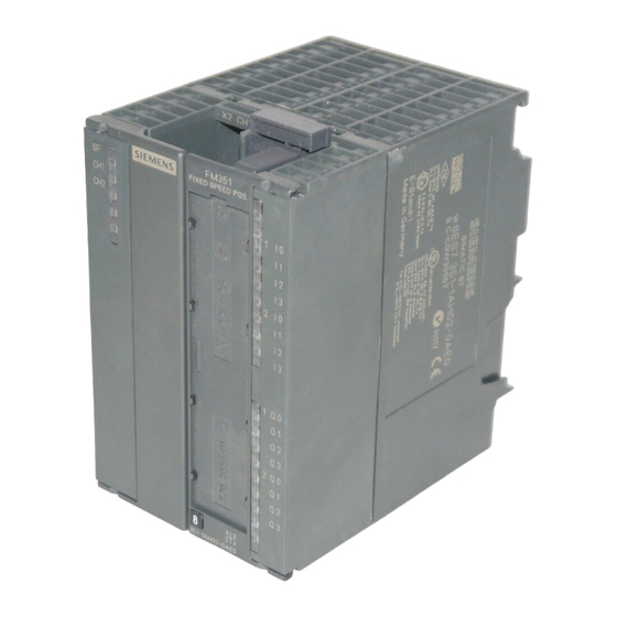
- Page 8 Contents Figures View of the FM 351 Positioning Function Module ..... FM 351 in the S7-300 ..........Example of a High-Bay Warehouse .
- Page 9 Contents Tables Assignment of the 15-Pin Subminiature Cannon Sockets X2 and X3 ..Front connector assignment ........4-10 Digital Input Functions .
- Page 10 Contents FM 351 Positioning Function Module EWA 4NEB 720 6001-02...
-
Page 11: Product Overview
Product Overview FM 351 The FM 351 Positioning Function Module for rapid and creep speed drives is used for controlled positioning. The module consists of two independent channels and can therefore control rotary or linear axes. An incremental or absolute encoder (SSI) can be connected to the module for each channel. The module operates automatically. -
Page 12: Fm 351 In The S7-300
Product Overview FM 351 in the The S7-300 Programmable Controller consists of a CPU and various signal S7-300 modules which are mounted on a rail. You can operate a number of FM 351 Positioning Function Modules simulta- neously. Combinations with other FM/CP modules are also possible. A typi- cal application is the combination with an FM 352 Electronic Cam Control- ler. -
Page 13: Fm 351 Fields Of Application
Product Overview FM 351 Fields of Application Fields of Below are a few examples from the field of controlled positioning which Application show the variation of applications possible with the FM 351. Control of Feed Various wooden parts are processed with a profile machine. Different work- Processes ing steps and routing heads are required to process the wood. -
Page 14: Components In Open-Loop Positioning
Product Overview Components in Open-Loop Positioning Control Circuit In Figure 1-4 you can see the control circuit and components of an open-loop positioning system. EMER- Line voltage GENCY FM 351 Positioning STOP Function Module Leistungs- Safety Power ansteue- device controller rung Processing stations... - Page 15 Product Overview Mechanical Trans- The mechanical transmission elements include: mission Elements Toothed belts (Axis) Spindle Toothed rack/pinion Hydraulic cylinder Gear unit Coupling systems The CPU executes the controlling user program (sequential program). Data and signals are interchanged via function blocks. PC/PG The PC/PG (programming device) is used for (Programming...
- Page 16 Product Overview FM 351 Positioning Function Module EWA 4NEB 720 6001-02...
-
Page 17: Principles Of Positioning
Principles of Positioning What Does Encoders supply pulses or numerical values as output signals. The encoder ’Controlled output signals describe the displacement of the load to be positioned. When Positioning’ the displacement reaches a specified setpoint, then with controlled position- Mean? ing the drive is switched over or switched off. - Page 18 Principles of Positioning If you carry out open-loop positioning with the FM 351, the drive is con- trolled with rapid and creep speeds in the appropriate direction using digital outputs. With the FM 351 Positioning Function Module for rapid and creep speed drives you can position two axes independently of one another.
-
Page 19: Ranges And Switching Points In The Region Of The Target Position
Principles of Positioning Ranges and Switching Points in the Region of the Target Position Introduction This chapter gives information about the combined effects of individual ma- chine data. You will find a description of the machine data in Chapter 8. Definition of the Each target position is characterized by a number of ranges which you para- Switching Points... -
Page 20: Positioning Velocity Curve
Principles of Positioning Positioning Velocity Curve Introduction This chapter gives an overview of the basic curve for positioning on a target. Velocity Curve on The velocity and also the basic curve mainly depend on the possibilities pro- Approaching a vided by the power controller which you are using. Target Position We show you the basic sequence on approaching a target position in Fig. -
Page 21: Target Approach
Principles of Positioning Target Approach Definition During a target approach the FM 351 makes various monitoring features and signals available. This achieves the following: The target approach is monitored. The signal Position reached is generated. You obtain the signal on the parameter POS_RCD of the FC INC_MOD (see Chapter 6.2.1). -
Page 22: Target Approach Of Positioning
Principles of Positioning Schematic: Target The figure clearly illustrates the sequence. Approach Target –1000 mm 1000 mm creep stand = Monitoring period Switchover difference, positive Switch-off difference, positive Standstill range Target range Standstill velocity reached Target range with v reached: POS_RCD is set stand Figure 2-4 Target Approach of Positioning FM 351 Positioning Function Module... -
Page 23: End Of Positioning
Principles of Positioning End of Positioning Definition You must differentiate between two cases for the end of positioning: The positioning is correctly terminated via the switchover and switch-off differences. This process is termed the end in the following. The positioning is immediately terminated by a “hard” action. This pro- cess is termed abort in the following. -
Page 24: Abort Of Positioning; The Signal Pos_Rcd Is Not Set
Principles of Positioning Abort Abort means that the positioning process is terminated immediately without application of the switchover and switch-off differences from the rapid and creep speeds to standstill. rapid POS_RCD is not set creep Abort Figure 2-6 Abort of Positioning; The Signal POS_RCD is Not Set FM 351 Positioning Function Module EWA 4NEB 720 6001-02... -
Page 25: Installing And Removing The Fm 351
Installing and Removing the FM 351 Planning the Information on the options of mechanical installation and how you must pro- Mechanical ceed during the project planning will be found in the manual S7-300 Pro- Installation grammable Controller, Hardware and Installation. Only supplementary information is given in the following. -
Page 26: Installing The Fm 351 Positioning Function Module
Installing and Removing the FM 351 Installing the FM 351 Positioning Function Module Rules No special protective measures (ESD guidelines) are required for the installa- tion of the FM 351 Positioning Function Module. Warning Only mount the FM 351 Positioning Function Module when the CPU is in the STOP operating state. -
Page 27: Removing The Fm 351 Positioning Function Module
Installing and Removing the FM 351 Removing the FM 351 Positioning Function Module Tool Required You will need a 4.5 mm (0.25 in) screwdriver to remove the FM 351 Posi- tioning Function Module. Procedure The following list describes how you remove the FM 351 Positioning Func- tion Module: 1. - Page 28 Installing and Removing the FM 351 FM 351 Positioning Function Module EWA 4NEB 720 6001-02...
-
Page 29: Wiring The Fm 351
Wiring the FM 351 Important Rules It is essential for the safety of the system to install the switching elements mentioned below and to adapt them to your system conditions. EMERGENCY STOP switch enabling you to switch off the complete sys- tem. -
Page 30: Wiring Diagram For An Open-Loop Positioning System
Wiring the FM 351 Wiring Diagram In Figure 4-1 you can see a wiring diagram for an open-loop positioning sys- tem using the FM 351 Positioning Function Module. FM 351 EMERGENCY STOP Enable Power Safety controller device Reference- point switch Encoder Motor Slide... - Page 31 Wiring the FM 351 Shielding The cable connections for the encoders should be implemented using shielded cables. To ensure operation free of interference it is essential that the connecting en- coder cables are grounded at both ends. The cable shield to the encoder must be joined both to the shield connector block on the FM 351 Positioning Func- tion Module as well as in the peripheral connector plug.
-
Page 32: Wiring The Power Controller
Wiring the FM 351 Wiring the Power Controller Power Controller The power controller is connected to the digital outputs on the FM 351. The motor is controlled by the power controller. The power controller may for example consist of a simple contactor circuit. Contactor Circuit In Figure 4-3 you can see the control and load circuits of a power controller. - Page 33 Wiring the FM 351 Working Principle The contactors K1 and K2 control the clockwise and counterclockwise motor of the Contactor rotation. Both contactors are interlocked against one another by the normally Circuit closed contacts K2 and K1. The limit switches E1 and E2 are the start/finish limit switches.
-
Page 34: Description Of The Encoder Interface
Wiring the FM 351 Description of the Encoder Interface Position of the The mounting position and the designation of the sockets on the module are Subminiature Can- shown in Figure 4-4. Incremental or absolute encoders (SSI) can be con- non Sockets nected to the two subminiature Cannon sockets. -
Page 35: Connecting The Encoders
Wiring the FM 351 Connecting the Encoders Selecting the Right You parameterize the type of encoder in the parameterization interface in the Encoder dialog field Encoder Data. Here, you can set the following types of encoders: 5 V incremental encoder 24 V incremental encoder Absolute encoder (SSI) –... -
Page 36: Connection Of An Encoder To The Fm 351 Positioning Function Module
Wiring the FM 351 Connecting the The connection of an encoder to the FM 351 Positioning Function Module is Encoders shown in Figure 4-5. Figure 4-5 Connection of an Encoder to the FM 351 Positioning Function Module Procedure Proceed as follows to connect the encoders: 1. -
Page 37: Description Of The Peripheral Interface
Wiring the FM 351 Description of the Peripheral Interface Position of the The FM 351 Positioning Function Module with the front doors open is illus- Front Connector trated in Figure 4-6. The front connector X1 is shown in the wiring position. Here you connect the supply voltages, switches and the power controller. -
Page 38: Front Connector Assignment
Wiring the FM 351 Front Connector Table 4-2 shows the assignment of the 20-pin front connector. Assignment Table 4-2 Front connector assignment Teminal Name Meaning 24 VDC encoder supply Ground, encoder supply 1I 0 Digital input 0 of channel 1 1I 1 Digital input 1 of channel 1 1I 2... -
Page 39: Digital Input Functions
Wiring the FM 351 Connected The ground of the encoder supply is non-isolated with respect to the CPU Potentials ground, that is, Terminal 2 (1M) should be connected with low resistance to the CPU ground. CPU 314 FM 351 Terminal 2 (1M) Ground 8 Digital Inputs The FM 351 has 4 digital inputs per channel. -
Page 40: Digital Output Functions
Wiring the FM 351 Function of the The power stage is controlled by the digital outputs. The function of the digi- Digital Outputs tal outputs depends on the control mode. You select the control mode in the parameterization interface. Table 4-4 Digital Output Functions Output Control Mode... -
Page 41: Wiring The Peripheral Interface
Wiring the FM 351 Wiring the Peripheral Interface Wiring the Front Figure 4-7 shows the wiring of the front connector. Connector Front connec- Figure 4-7 Wiring of the Front Connector Connecting Wires Flexible wire, cross-sectional area 0.25 mm to 1.5 mm Wire end ferrules are not required. - Page 42 Wiring the FM 351 Procedure To wire the front connector, proceed as follows: 1. Strip 6 mm (0.25 in) from the wire, fitting a wire end ferrule if required. 2. Open the front door, bring the front connector to the wiring position. 3.
-
Page 43: Fm 351 Parameterization
FM 351 Parameterization Introduction You parameterize the positioning module with the parameterization software. The software is intended for the FM 351 and the FM 451. The description of operation can be found in the integrated help. Requirements Before you begin the parameterization of the FM 351 Positioning Function Module, you should check the following requirements: STEP 7 from V2.0 is correctly installed on your programming device/PC. - Page 44 FM 351 Parameterization Configuration For configuration it is assumed that you have created a project in which you can store the parameterization. You will find further information on the con- figuration of modules in your user manual Standard Software for S7 and M7, STEP 7.
- Page 45 FM 351 Parameterization Integrated Help The parameterization interface is equipped with integrated help which sup- ports you when parameterizing the positioning module. You call the inte- grated help as follows: Via the menu command Help Help topics... By pressing the F1 key. Supply Channel Before you program the module with the user program, you must supply the channel DB with important data.
- Page 46 FM 351 Parameterization FM 351 Positioning Function Module EWA 4NEB 720 6001-02...
- Page 47 Programming the FM 351 The Programming In order that you can use the FM 351 effectively, you have the functions Package available in the form of a number of FCs. These function blocks are subdi- vided into three groups: Function blocks (FCs) which control the FM 351. Function blocks (FCs) which write data, settings and commands to the FM 351.
-
Page 48: Entries In The Channel Db
Programming the FM 351 Principles of Programming an FM 351 Requirements for The following requirements must be fulfilled if you want to control the Programming FM 351 from your user program: Your S7-300 system must be configured. STEP 7 from Version 2.0 must be installed on a computer. The computer must be connected to the CPU on the S7-300. -
Page 49: Programming The Fm 351
Programming the FM 351 Programming When you now write your program code, note that you only need to link the Rules FCs which you actually need for your application. Make sure that the separately written functions are mutually interlocked. Generally, only one write job at a time may be executed on the FM 351. Irrespective of the extent of the interlocks which you program, you should ensure that the FC DIAG_INF is only called when really needed, that is with a diagnostic interrupt. -
Page 50: Principle Of Communication Between Cpu And Fm 351
Programming the FM 351 6.1.1 Principle of Communication between CPU and FM 351 Introduction We introduced you to the three-way subdivision of the function blocks for the FM 351 in the overview to Chapter 6. In this Chapter we will show you how the separate function blocks control the communication between the CPU and FM 351. -
Page 51: Principle Of Communication Between The Cpu And Fm
Programming the FM 351 Communication The following summarizing figure shows you how a communication is executed. The following abbreviations are used in the figure: MD = Machine data IT = Incremental table (set values) DB* = Channel DB for channel * User program FC INC_MOD DB1 for... -
Page 52: Calling Functions
Programming the FM 351 6.1.2 Calling Functions Requirements When you link the FM 351 into your program, please pay attention to the following requirements. The parameterization for the two channels in the FM 351 has been com- pleted. That is, there is valid data in the CPU. The channel DB is present and assigned appropriate to the configuration of the system. - Page 53 Programming the FM 351 Decentralized Per channel always only one mode block may be called and active. Operation For each module you must ensure that: Always only one FC for the writing of data is called and active. Parallel to this, one FC for the reading of data is called and active. Interlocking the You must prevent the parallelism of a number of function calls and writing FC Calls...
-
Page 54: Interrupt Handling
Programming the FM 351 6.1.3 Interrupt Handling Types of Interrupt The FM 351 can release diagnostic interrupts in the CPU. Requirements You must have programmed the diagnostic interrupt OB for handling diag- nostic interrupts. Note If you have not programmed the interrupt OB (OB 82), the CPU goes to STOP in the event of an interrupt. -
Page 55: Evaluating The Diagnostic Information From The Fm
Programming the FM 351 Calling the FC You read the diagnostic information from the FM 351, depending on the pa- DIAG_INF in OB 1 rameter DIAGNOSTIC INTERRUPT, in OB1 or in an FC which is called from OB 1. Explanation CALL DIAG_INF( // Call FC DIAG_INF... -
Page 56: Functions Which Control The Fm
Programming the FM 351 Functions which Control the FM 351 Definition In the FM 351 programming package there are functions which you can call as required for all operating modes. Table 6-4 Brief Description of the Mode FCs Function Brief Description of the Task FC INC_MOD The incremental mode is the standard mode for the FM 351. - Page 57 Programming the FM 351 OT_ERR If it is not possible to call an operating mode or the control of an active oper- ating mode is not possible or has been incorrectly carried out, the relevant module signals this by setting the parameter OT_ERR. The operating mode cannot be controlled until the error is acknowledged by a signal on the input OT_ERR_A.
- Page 58 Programming the FM 351 6.2.1 FC INC_MOD Task The FC INC_MOD is the main block for programming the FM 351. When the FC is called you immediately set the incremental operating mode. This is independent of the assignment of the individual parameters. The FM 351 signals the acceptance of the operating mode with the set pa- rameter INC_MD_A.
- Page 59 Programming the FM 351 Description of the The following table describes the parameters in the function block Parameters FC INC_MOD. Name Data Type P Type Meaning DB_NO BLOCK_DB Channel DB number. DRV_EN BOOL Drive enable; the missing signal initiates an abort of the current position- ing.
-
Page 60: Fc Jog_Mode
Programming the FM 351 6.2.2 FC JOG_MODE Task With the FC JOG_MODE you set the jogging operating mode. All commands and parameters are specified with the FC. The FC carries out the following actions: Sets the jogging operating mode. Controls the jogging operating mode. Reads the check-back signals (for example, the actual value). - Page 61 Programming the FM 351 Name Data Type P Type Meaning JP_JOG BOOL Jog mode running; TRUE - running FALSE - is terminated Parameter types: I = Input Parameter; O = Output Parameter; I/O = In/Out Parameter (start parameter). FM 351 Positioning Function Module 6-15 EWA 4NEB 720 6001-02...
-
Page 62: Fc Ref_Mode
Programming the FM 351 6.2.3 FC REF_MODE Task With the FC REF_MODE you start the seek-reference-point mode. The FC executes the following actions: Sets the seek-reference-point operating mode. Controls the seek-reference-point operating mode. Reads the check-back signal (for example, actual value). The read values are saved by the FC in the channel DB (CHECKBACK_SIGNALS). - Page 63 Programming the FM 351 Name Data Type P Type Meaning DIR_P BOOL Direction positive - starts seek-reference-point in positive direction. DIR_M BOOL Direction negative - starts seek-reference-point in negative direction. Parameter types: I = Input Parameter; O = Output Parameter; I/O = In/Out Parameter (start parameter). FM 351 Positioning Function Module 6-17 EWA 4NEB 720 6001-02...
-
Page 64: Functions Which Write Data To The Fm 351
Programming the FM 351 Functions which Write Data to the FM 351 Write Definition All functions which transfer data to a channel in the FM 351 are included in the group of write functions. The data is situated in the channel DB. Introducing the In Table 6-6 you will find all the FCs which have write access to the FM 351 channels. - Page 65 Programming the FM 351 Task of all FCs Irrespective of their specific task, all FCs read the check-back signals from the FM 351 (for example, the momentary actual value). The read values are then entered by the relevant FC in the channel DB. Note The read values give the status which the FM351 had before the call (for example, the actual value before the call setting the reference point).
- Page 66 Programming the FM 351 Name Data Type P Type Meaning JP_**** BOOL The FC signals the data transfer status with this parameter. TRUE - Data transfer is active. FALSE - Data transfer is terminated. For each FC the **** must be substituted by the specific designation. EN;EN0 BOOL This parameter is only necessary in the LAD representation.
-
Page 67: Fc Refpt
Programming the FM 351 6.3.1 FC REFPT Task With the FC REFPT you call Set reference point. The FC executes the fol- lowing actions: Transfer of the value for the setting of the reference point from the chan- nel DB to the FM 351. The FM 351 sets the new reference point if no error occurs. - Page 68 Programming the FM 351 Calling Example The following shows you a calling example for the function FC REFPT. Explanation Write fct_R; // No new function start. REFP; // Call FC REFPT. L#1000; DB_ABS.SETTING_REFERENCE_POINT; // Enter reference point // in channel DB. Start_write fct;...
-
Page 69: Fc Act_Val
Programming the FM 351 6.3.2 FC ACT_VAL Task With the FC ACT_VAL you call Set actual value. The FC carries out the following actions: Transfer of the value for setting the actual value from the channel DB to the FM 351. By calling the FC you set a new actual value for the current axis position. -
Page 70: Fc Sng_Fct
Programming the FM 351 6.3.3 FC SNG_FCT Task With the FC SNG_FCT you can call the individual settings Creep speed and Do not evaluate enable input on the FM 351. The FC carries out the follow- ing actions: Transfer of the data area SINGLE_FUNCTIONS from the channel DB to the FM 351. -
Page 71: Fc Sng_Com
Programming the FM 351 6.3.4 FC SNG_COM Task With the FC SNG_COM you call the single commands Undo set actual value and Delete residual distance on the FM 351. The FC carries out the following actions: Transfer of the data area SINGLE_COMMANDS from the channel DB to the FM 351. -
Page 72: Fc Tg254
Programming the FM 351 6.3.5 FC TG254 Task With the FC TG254 you transfer the Increment 254 for the incremental oper- ating mode. The FC carries out the following actions: Transfer of the value for the Increment 254 to the FM 351. Calling Methods Calling in LAD Representation Calling in STL Representation... -
Page 73: Fc Tg253_5
Programming the FM 351 6.3.6 FC TG253_5 Task With the FC TG253_5 you transfer the Increment 255 and the values for the switch-off and switchover difference for the incremental operating mode to the FM 351. The FC carries out the following actions: Transfer of the values for the Increment 255 to the FM 351. -
Page 74: Functions Which Read Data From The Fm 351
Programming the FM 351 Functions which Read Data from the FM 351 Read Definition All data which is to be read from a channel on the FM 351 is included in the group of reading functions. The reading of the check-back signals which is carried out by each FC is not included. - Page 75 Programming the FM 351 Binary Result BIE All FCs affect the binary result BIE: BIE=1: the data transfer has been terminated without any errors. BIE=0: the data transfer has been terminated with an error. In the case of an error (BIE=0) the parameter RET_VAL provides further information.
- Page 76 Programming the FM 351 6.4.1 FC DIAG_INF Task With the FC DIAG_INF you read the diagnostic information in the event of a diagnostic interrupt from the FM 351. The FC carries out the following ac- tions: Reading of 14 bytes of diagnostic information from the FM 351 and en- tering in the channel DB in the data area DIAGNOSTIC_INT_INFO.
- Page 77 Programming the FM 351 6.4.2 FC ACT_DAT Task With the FC ACT_DAT you read the basic operating data or the service data from the FM 351. The FC carries out the following functions: Reading of the data from the FM 351 and entry in the channel DB: –...
-
Page 78: Programming Example
Programming the FM 351 Programming Example Introduction On the enclosed diskette you will find a programming example with which you can test the basic functional features of the FM 351. In this chapter we describe the required surrounding conditions and the controlling elements. Parameterization In this example project special machine data is deposited. - Page 79 Programming the FM 351 Hardware The example is designed for the following hardware set-up: A programming device (for example, PG 740) with STEP 7 software installed from Version 2.0 must be present. Two simulation modules (32 digital inputs) in slots 3 and 4. Two simulation modules (32 digital outputs) in the slots 5 and 6.
- Page 80 Programming the FM 351 Input Marker Description Output Marker Description Delete interrupt display Delete error display Marker The table gives a brief overview of the memory markers used. Marker Description M 31.0 Write function running M 31.1 Edge trigger flag for write initiation M 31.2 Start parameter for write function M 31.3...
-
Page 81: Technical Data
Programming the FM 351 Technical Data Technical Data The following table gives you an overview of the technical data of the FM 351 technological functions. Table 6-10 Technical Data for the FM 351 Technological Functions Block Block Name Version Space Space Space Space... - Page 82 Programming the FM 351 FM 351 Positioning Function Module 6-36 EWA 4NEB 720 6001-02...
-
Page 83: Setting Up The Fm 351
Setting Up the FM 351 Introduction In this chapter we would like to show in a few steps how you can set up the FM 351. HW Installation To obtain a better overview, the procedure Set-up is subdivided into a num- and Wiring ber of small steps. - Page 84 Setting Up the FM 351 Configuring the Now configure the project under STEP 7 such that parameterization with the Project parameterization mask is possible. Step What Must Be Done? Configure a new project under STEP 7. Build up a new rack. Enter your hardware installation into the rack with the configuration interface.
- Page 85 Setting Up the FM 351 Setting Up the Check for the correct parameterization of the FM 351 with the following FM 351 table. Step What Must Be Done? Select the Jog operating mode. Check that the outputs are correctly wired (type of control). –...
- Page 86 Setting Up the FM 351 Saving the Project Once you have successfully concluded all tests and the FM 351 parameteriza- tion has been optimized, you must save the data and prepare the system for the standard operating mode. Step What Must Be Done? Save all data in the parameterization interface with File Save.
-
Page 87: Machine Data And Increments
Machine Data and Increments What is Machine You adapt the FM 351 to the axes with the machine data. Data For? Positioning with the FM 351 is only possible, if correct machine data exists on the module. Increments Increments are specified targets, the approach to which is controlled by the FM 351 with the relative or absolute incremental mode. -
Page 88: Basic Data
Machine Data and Increments Basic Data Starting Before you parameterize your FM 351, you must Parameterizing select a special unit and create the required channels for the entry of the data in the parameterization interface. The selected system of units is then used both for the input as well as for the output of the data. - Page 89 Machine Data and Increments System of Units in In this chapter we use the mm system of units when stating the minimum this Chapter and maximum values. For determining the limits in the other systems of units, apply the following calculation: For the Conversion of Calculate –1...
-
Page 90: Machine Data For The Drive
Machine Data and Increments Machine Data for the Drive Definition The machine data for the drive describes: How the FM 351 can control a drive (power controller) using its outputs. How a target approach is executed and monitored. Data List All data for the Drive input range can be found in the following table: Table 8-2 Drive Data... - Page 91 Machine Data and Increments Table 8-2 Drive Data, continued Machine Data and Description Assignment Control type 4 rapid 1Q0/2Q0: Rapid speed, positive creep 1Q1/2Q1: Creep speed, positive 1Q2/2Q2: Rapid speed, negative 1Q3/2Q3: Creep speed, negative Switchover difference posi- The switchover difference defines the switchover point in the travel range at which the tive/negative und drive switches over from rapid to creep speed.
- Page 92 Machine Data and Increments Table 8-2 Drive Data, continued Machine Data and Description Assignment Standstill range The standstill range is used for monitoring for standstill. Whether the drive remains stationary at the approached position or drifts away is monitored. 0 mm to 1 000 000.000 mm at a If the standstill range is left, an error is signaled.
-
Page 93: Machine Data For The Axis
Machine Data and Increments Machine Data for the Axis Definition The axis has the input ranges: Axis type Entries for the reference point on the axis Axis limits Data List The description of all data for the axis input range can be found in Table 8-3. Table 8-3 Machine Data for the Axis Machine Data and... - Page 94 Machine Data and Increments Table 8-3 Machine Data for the Axis, continued Machine Data and Description Assignment Reference point Incremental encoder: coordinate You determine the reference point by synchronization, that is, via the setting Set ref- – 1,000,000.000 mm erence point or the Seek-reference-point mode. If the synchronization event is de- tected (for example, zero mark of the encoder during a seek-reference-point travel), the reference coordinate is allocated to this event.
- Page 95 Machine Data and Increments Table 8-3 Machine Data for the Axis, continued Machine Data and Description Assignment Starting velocity for seek- With this data you select the velocity for the start of a seek-reference-point travel: reference-point travel: Rapid speed Rapid speed Creep speed Creep speed Software limit switch...
-
Page 96: Absolute Encoder Adjustment
Machine Data and Increments Absolute Encoder Adjustment Definition The absolute encoder adjustment provides a permanent relationship between the coordinate system and the encoder. What You Define When you parameterize your FM 351 with the parameterization interface, the values that you define include the following: Software Limit Switches Start (SLS) and End (SLE);... - Page 97 Machine Data and Increments Determining the After the initial parameterization further steps are necessary to create a cor- Correct Absolute rect relationship between the encoder and the coordinate system. Encoder Adjust- 1. Set the axis to a defined reproducible point with which you are familiar ment and which is physically unambiguous.
- Page 98 Machine Data and Increments Extended Travel The encoder supplies 2048 unambiguous values. The working range is de- Range fined by the software limit switches. Due to the selected resolution of 1 mm per increment, the encoder can cover a larger working area. With the set resolution the working range is already covered with 2001 val- ues.
-
Page 99: Machine Data For The Encoder
Machine Data and Increments Machine Data for the Encoder Definition The encoder supplies the displacement information to the module which evaluates it and converts to an actual value using the resolution. It is only by correctly specifying the machine data of the encoder that you can ensure that the determined actual value of the axis position matches the real axis position. - Page 100 Machine Data and Increments Table 8-4 Machine Data for the Encoder, continued Machine Data and Description Assignment Increments per encoder The machine data Increments per encoder revolution gives the number of increments revolution which the encoder produces per revolution. The FM 351 determines the resolution from this value and the machine data Displacement per encoder revolution.
- Page 101 Machine Data and Increments Table 8-4 Machine Data for the Encoder, continued Machine Data and Description Assignment No. of revolutions This machine data is only required for absolute encoders. You use it to define the num- ber of revolutions possible with this encoder. 1, 2, 4, 8, 16, 32, 64, 128, 256, 512, 1024, If you would like to know more about absolute encoders, please read Chapter 10.3 of...
-
Page 102: Resolution
Machine Data and Increments Resolution Definition The resolution is not a direct item of machine data. It is however found by the FM 351 from the two items of machine data: Displacement per encoder revolution. Pulses per encoder revolution. With incremental encoders the quadruple evaluation is also taken into ac- count. -
Page 103: Incremental Dimensions
Machine Data and Increments Incremental Dimensions Definition Incremental dimensions are specified target values which can be approached by the FM 351 with the relative or absolute incremental operating mode. You have the possibility of entering a maximum of 100 incremental dimen- sions in a table. -
Page 104: Symmetrical Position Of The Switch-Off And Switchover Points For Increment
Machine Data and Increments Standard Incre- In the parameterization interface you must enter the incremental dimensions ments 1 to 100 in an increment table. The list has space for a maximum of 100 increments which are valid for the Relative incremental mode as well as for the Abso- lute incremental mode. -
Page 105: Operating Modes And Settings
Operating Modes and Settings Operating Modes The task of an FM 351 is the positioning of a drive at certain specified tar- gets. For these tasks the FM 351 has the following operating modes available: Jogging The drive is driven for the duration of the key depression. Incremental –... - Page 106 Operating Modes and Settings Calling Options Basically, you have the option of conveniently calling all the settings. To do this, you select: The parameterization interface with which you comprehensively test and set up the FM 351. The FCs which you can link into your program. In this chapter we only show you the calling of the single FCs.
-
Page 107: Generally Applicable Definitions
Operating Modes and Settings Generally Applicable Definitions Travel Range The maximum possible travel range is determined by the number representa- tion in the FM 351. Caution The travel range of the FM 351 may be larger than the maximum range of the physical axis. -
Page 108: Jogging Operating Mode
Operating Modes and Settings Jogging Operating Mode Definition In the Jogging operating mode you move the drive in one direction with the pressing of a key. You must install a key for each direction (positive and neg- ative). Requirements The following requirements must be fulfilled for the start of the operating mode: The axis must be parameterized. -
Page 109: Jogging With A Synchronized And Non-Synchronized Axis
Operating Modes and Settings Aborting Jogging Aborting is a process with which the otherwise normal sequence of a target approach is not carried out (see Chapter 2.2) “Jogging” is aborted when: The signal Drive enable is deleted. A traverse range limit is crossed with a linear axis. Speeds With the FM 351 jogging is possible at two speeds: Jogging at rapid speed. -
Page 110: Seek-Reference-Point Operating Mode
Operating Modes and Settings Seek-Reference-Point Operating Mode Definition You synchronize the FM 351 with the Seek-reference-point mode. Synchronization with a seek-reference-point traverse is only necessary with incremental encoders. A seek-reference-point traverse must be carried out for each channel. The synchronization of pulse counters and the axis is necessary: So that your drive can approach an absolute target. -
Page 111: Start Commands For A Seek-Reference-Point Traverse
Operating Modes and Settings Speeds You can define a speed for the start of a seek-reference-point traverse: Start with creep speed. Start with rapid speed. Calling the Seek- You call the seek-reference-point mode: Reference-Point In the mask for setting up the parameterization interface. Mode With the FC REF_MODE. -
Page 112: Starting A Seek-Reference-Point Traverse
Operating Modes and Settings Take note of the following table. It shows you the four types of seek-refer- ence-point mode. Table 9-3 Types of Seek-Reference-Point Mode Start Direction is... For Synchronization use... positive The first zero mark after leaving the reference-point switch in positive direction. positive The first zero mark after leaving the reference-point switch in negative direction. -
Page 113: Possibilities For The Seek-Reference-Point Mode
Operating Modes and Settings Possibilities for the Seek-Reference-Point Mode Seek-Reference- With a seek-reference-point traverse there are five different cases which are Point Traverse in dependent: Dependence of the On the position of the drive on starting a seek-reference-point traverse. Start Position On the parameterized start direction. - Page 114 Operating Modes and Settings Table 9-4 All Possibilities for a Seek-Reference-Point Mode, continued Conditions for the Seek-Reference-Point Mode Sequence of the Seek-Reference-Point Mode At the start of the seek-reference-point mode the drive is located at the reference-point switch. Position of the zero mark from the reference-point switch is parameterized negatively.
-
Page 115: Incremental Operating Mode
Operating Modes and Settings Incremental Operating Mode Definition With the incremental mode the FM 351 can: Move the drive to absolute targets. Move the drive relatively by a displacement in a specified direction. The target position or the relative displacements are specified for the FM 351 as incremental dimensions. -
Page 116: Starting The Incremental Mode
Operating Modes and Settings Starting 1I2; 2I2 Sequence Start, DIR_P, DIR_M WORKING WAIT_EN rapid creep Figure 9-3 Starting the Incremental Mode Start Command The methods of starting an incremental mode are dependent on: The type of incremental mode (relative or absolute). The type of axis. - Page 117 Operating Modes and Settings Residual Distance With the relative incremental mode a residual distance remains, if the rela- with Relative tive incremental mode was terminated by STOP. Incremental Mode The remaining residual distance can be traversed to the end if: The operating mode is unchanged, The incremental dimension number is unchanged, The direction is unchanged and...
-
Page 118: Setting Set Actual Value
Operating Modes and Settings Setting Set Actual Value Definition With the setting Set actual value you allocate a new coordinate to the current encoder location. The working range is projected to a different physical range on the axis. Therefore, you do not change any coordinate values. The displacement of the working range is determined by ACT current is the specified value. -
Page 119: Displacement Of The Working Range On The Axis By Set Actual Value
Operating Modes and Settings Table 9-6 Displacement of the Working Range on the Axis by Set Actual Value Set Actual Value [mm] –500 -400 -200 Projection of the working the working range by Set actual value to 300 mm -400 -200 –500 All numerical values are given in the units of mm. -
Page 120: Setting Set Reference Point
Operating Modes and Settings Setting Set Reference Point Definition With the setting Set reference point you synchronize the axis. Requirements Take note of the following requirements for this setting: The channel must be parameterized. Linear axis: The reference-point coordinate must not be located outside the software limit switches. -
Page 121: Single Setting Loop Traverse
Operating Modes and Settings Single Setting Loop Traverse Definition With the single setting Loop traverse you define the direction in which a target is approached. A target which is approached against the specified direction is first passed by. Then the FM 351 carries out a reversal of direction and approaches the target in the specified direction. -
Page 122: Loop Traverse To A Target At The Software Limit Switch End
Operating Modes and Settings Requirements Take note of the following requirements for a loop traverse: If you have parameterized a loop traverse against the traverse direction to the target, the target position which can be approached at a maximum is located at: –... -
Page 123: Single Setting Do Not Evaluate Enable Input
Operating Modes and Settings Single Setting Do Not Evaluate Enable Input Definition The start of an operating mode for a channel is normally only possible, if the appropriate enable input is set: Digital input 1I2 for Channel 1 Digital input 2I2 for Channel 2 You therefore have the possibility of preparing an operating mode for start- ing. - Page 124 Operating Modes and Settings FM 351 Positioning Function Module 9-20 EWA 4NEB 720 6001-02...
- Page 125 Encoders Encoders which You can connect the following encoders to the positioning function module: You Can Connect Incremental encoders Absolute encoders (SSI) Chapter Overview In this chapter you will find information in the following sub-chapters: Section Heading Page 10.1 Incremental Encoders 10-2 10.2 Selecting an Incremental Encoder...
-
Page 126: Signal Waveforms From Incremental Encoders
Encoders 10.1 Incremental Encoders Incremental The FM 351 Positioning Function Module supports two types of incremental Encoders encoder: Incremental encoders (25 V) with asymmetrical output signals. Incremental encoders (5 V) with symmetrical output signals. Signal Waveforms The signal waveforms from encoders with asymmetrical and symmetrical output signals are illustrated in Figure 10-1. -
Page 127: Selecting An Incremental Encoder
Response time = 150 µs Blurring Blurring affects the positioning accuracy. With incremental encoders the blurring is negligible. Manufacturer We recommend that you use incremental encoders from SIEMENS (see Appendix B). FM 351 Positioning Function Module 10-3 EWA 4NEB 720 6001-02... -
Page 128: Absolute Encoders
Encoders 10.3 Absolute Encoders Single-Turn and There are the following absolute encoders: Multi-Turn Single-turn encoders Encoders Single-turn encoders form the total encoder range on one encoder revolu- tion. You can use single-turn encoders with the following steps per revo- lution: –... -
Page 129: Selecting An Absolute Encoder
Encoders 10.4 Selecting an Absolute Encoder Absolute Encoders You can connect single-turn encoders (13 or 25 bit frame length) or multi- turn encoders (25 bit frame length) to the FM 351 Positioning Function Mod- ule (see Chapter 10.3). Response Times The following response times apply to absolute encoders (SSI): Min. - Page 130 For programmed absolute encoders: Blurring = Frame transfer time + Monostable flipflop period +1/max. step sequence frequency Manufacturer We recommend that you use absolute encoders from SIEMENS (see Appendix B). FM 351 Positioning Function Module 10-6 EWA 4NEB 720 6001-02...
-
Page 131: Error Handling
Error Handling Preliminary The FM 351 Positioning Function Module provides diagnostic possibilities Remarks for: Errors on the module and the connected peripherals. Errors which occur when controlling the module. Purpose of this This chapter describes the procedure during the error evaluation for the Chapter FM 351. -
Page 132: Status And Error Indicators On The Fm
Error Handling 11.1 Module Defects Purpose When the FM 351 starts up, that is, the power supply is switched on (“Power on”), the FM 351 goes through a general module test (that is, RAM test and EPROM test). Effect If the module is faulty and not ready, then the FM 351 remains in a safe state, the LED “SF”... -
Page 133: Diagnostic Interrupts
Error Handling 11.2 Diagnostic Interrupts Purpose Errors leading to a diagnostic interrupt are monitored for their “incoming” and “outgoing”. The FM 351 signals “incoming” errors by: Lighting the LED “SF” (see Fig. 11-1). Maybe also lighting the LEDs “CH1” or “CH2”. Setting the Bit 0.0 in OB 82 (OB82_MDL_DEFECT). - Page 134 Error Handling FM 351 Response When a diagnostic interrupt occurs, the FM provides a defined system state to an Error with due to the following actions: Diagnostic The positioning is aborted. Interrupt The synchronization is deleted if: – The external auxiliary voltage is missing, –...
- Page 135 Error Handling How Can the Diag- When the FM 351 initiates a diagnostic interrupt: nostic Interrupt Be The system makes four bytes of interrupt information available in the in- Localized? terrupt OB (OB 82) (see Table 6-3). Further diagnostic bytes are accessible via the FC DIAG_INF which are entered in the FC in the relevant channel DB.
-
Page 136: Diagnostic Interrupts For Internal Errors
Error Handling Diagnostic The following table shows all diagnostic interrupts output by the FM 351. Interrupts The byte details in the following table are relative to the Address 72.0 of the relevant channel DB. Table 11-1 Diagnostic Interrupts for Internal Errors Error Signal, Event Number... - Page 137 Error Handling Table 11-1 Diagnostic Interrupts for Internal Errors, continued Error Signal, Event Number Error Analysis and Rectification Encoder wire breakage 0x8090 Cause Encoder cable cut or not plugged in. 10.0 Encoder has no quadrature signals. Incorrect pin assignment. Cable length too long. Encoder signals short circuited.
- Page 138 Error Handling Table 11-1 Diagnostic Interrupts for Internal Errors, continued Error Signal, Event Number Error Analysis and Rectification Error pulses in incremental encoders 0x8092 Cause Encoder monitoring has found error pulses. 10.2 Number of increments per encoder revolution is incorrectly entered. Encoder defective: Does supply the specified number of pulses.
- Page 139 Error Handling Table 11-1 Diagnostic Interrupts for Internal Errors, continued Error Signal, Event Number Error Analysis and Rectification Operating errors 0x8097 Cause The following operating errors may occur: 10.7 Software limit switch passed. Limit of traverse range passed. Error on target run-in. Standstill range left.
-
Page 140: General Errors
Error Handling 11.3 General Errors Purpose If there are no module defects or diagnostic interrupts present, then you can localize general errors on the module with the parameterization software. General errors are: Parameterization errors during test and set-up with the parameterization software. -
Page 141: Channel Db Structure
Structure of the Channel DB Purpose of the The channel DB is the data interface between the user program and the Channel DB FM 351 Positioning Function Module. All data belonging to one channel of the FM 351 Positioning Function Mod- ule are located in the channel DB of the FC INC_MODE. -
Page 142: Contents In The Channel Db
Structure of the Channel DB Contents in the Table 12-1 below describes the contents of the channel DB with the Channel DB associated absolute and symbolic addresses. Table 12-1 Contents in the Channel DB Address Decla- Variable Data Starting Description ration Type Value... - Page 143 Structure of the Channel DB Table 12-1 Contents in the Channel DB, continued Address Decla- Variable Data Starting Description ration Type Value Check-back signals 28.0 stat CHECKBACK_SIGNALS. STRUCT --- Check-back signals 28.7 stat ... PARA BOOL FALSE TRUE: Module is parameterized FALSE: Module is not parameter- ized 29.0 stat...
- Page 144 Structure of the Channel DB Table 12-1 Contents in the Channel DB, continued Address Decla- Variable Data Starting Description ration Type Value Check-back signals 31.5 stat ... FAVAL BOOL FALSE Not used 31.7 stat ... POS_RCD BOOL FALSE TRUE: Position reached FALSE: Position not reached 32.0 stat ...
- Page 145 Structure of the Channel DB Table 12-1 Contents in the Channel DB, continued Address Decla- Variable Data Starting Description ration Type Value Diagnostic data 76.0 stat ... BYTE 4 BYTE B#16#0 Channel diagnosis: DS1 77.0 stat ... BYTE 5 BYTE B#16#0 (see Table 6-3) 78.0 stat...
- Page 146 Structure of the Channel DB FM 351 Positioning Function Module 12-6 EWA 4NEB 720 6001-02...
- Page 147 Technical Specifications Purpose of this This chapter acts as a reference chapter. It describes the technical data for the Chapter FM 351 Positioning Function Module. General technical data Dimensions and weight Encoder inputs Digital inputs Digital outputs Chapter Section Contents Page Overview General Technical Specifications...
- Page 148 “Electromagnetic Compatibility” and the harmonized European standards (EN) listed therein. The EU declarations of conformity are kept according to the above-men- tioned EU Directive, Article 10 for the responsible authorities at: Siemens Aktiengesellschaft Bereich Automatisierungstechnik AUT E 148 Postfach 1963...
- Page 149 Technical Specifications Area of SIMATIC products have been designed for use in the industrial area. Application SIMATIC products may also be used in the domestic environment (house- hold, business and trade area, small plants) with individual approval which must be obtained from the respective national authority or testing body. Area of Application Requirements Emitted interference...
- Page 150 Technical Specifications Special Technical Data General Technical General technical data is: Data Electromagnetic compatibility Transport and storage conditions Mechanical and climatic ambient conditions Details on insulation tests, class and level of protection. This general technical data contains standards and test values which the S7-300 maintains and fulfills, as well as to which test criteria the S7-300 was tested.
- Page 151 Technical Specifications Current Consumption and Power Supply of digital inputs and outputs Supply voltage: 24 VDC (permissible range: 20.4 to 28.8 V) Current consumption from 2L+ (without load): Max. 50 mA (X1, Terminal 19) Permissible potential difference between input ground connection 1M (X1, Terminal 2) –...
- Page 152 Technical Specifications Digital Inputs Input current 0-signal: 2 mA (quiescent current) 1-signal: 6 mA Input delay (1Q0, 1Q1, 1Q2 and 2Q0, 2Q1, 2Q2) 1-signal: typ. 3 ms 0-signal: typ. 3 ms 1-signal: typ. 300 µs Input delay (1Q3 and 2Q3) 0-signal: typ.
- Page 153 Connecting cable for incremental encoder Siemens 6FX 2001-2 (Vp=24V; RS 422) Connecting cable for incremental encoder Siemens 6FX 2001-4 (Vp=24V; HTL) Connecting cable for absolute encoder Siemens 6FX 2001-5 (Vp=24V; SSI) FM 351 Positioning Function Module EWA 4NEB 720 6001-02...
-
Page 154: B.2 Connecting Cable For Incremental Encoder Siemens 6Fx
Ordering The cable cross-sectional areas are stated in the figure. The maximum length Information of the connecting cable, matching the incremental encoder Siemens 6FX 2001-2 (V =5 V; RS 422), is 32 m shielded. The relevant order number 6ES5 703-1xxx0 (xxx: Length code see catalog...) The connecting cable can also be obtained without an encoder connector (open cable end). - Page 155 Ordering The cable cross-sectional areas are stated in the figure. The maximum length Information of the connecting cable, matching the incremental encoder Siemens 6FX 2001-2 (Vp=24 V; RS 422), is 100 m shielded. The relevant order num- ber is: 6ES5 703-7xxx0 (xxx: Length code see catalog...) The connecting cable can also be obtained without an encoder connector (open cable end).
- Page 156 The cable cross-sectional areas are stated in the figure. The maximum length Information of the connecting cable, matching the incremental encoder Siemens 6FX 2001-4 (Vp=24 V; HTL), is 100 m shielded. The relevant order number 6ES5 703-8xxx0 (xxx: Length code see catalog...) The connecting cable can also be obtained without an encoder connector (open cable end).
-
Page 157: B.4 Connecting Cable For Absolute Encoder Siemens 6Fx
The cable cross-sectional areas are stated in the figure. The maximum length Information of the connecting cable, matching the absolute encoder Siemens 6FX 2001-5, is 320 m shielded at a baud rate of 125 KHz. The relevant order number is: 6ES5 703-9xxx0 (xxx: Length code see catalog...) - Page 158 Connecting Cables FM 351 Positioning Function Module EWA 4NEB 720 6001-02...
- Page 159 Glossary Absolute Encoder An absolute encoder determines the displacement traveled by reading off a numerical value. Absolute Encoder The absolute encoder adjustment provides a fixed relationship between the Adjustment coordinate system and the encoder. The following values are required for this: Absolute encoder adjustment: This is a value from the value range of the absolute encoder.
- Page 160 Glossary Enable Input The enable input is a digital input per channel on the positioning module. A positioning process is started and stopped with the enable input. Encoder Encoders are used for the exact measurement of distances, positions and speeds. Evaluate Enable As standard the positioning module evaluates the enable input of the relevant Input...
- Page 161 Glossary Multi-Turn Encoder Multi-turn encoders are absolute encoders. The resolution is determined over a number of coded disks. Positioning Positioning means to bring a load to a defined position in a certain time tak- ing into account all the forces and moments acting. Positioning The positioning module for rapid and creep speed drives is a function module Module for Rapid...
- Page 162 Glossary Resolution The resolution is determined from the ratio of the machine data: Displacement per encoder revolution Pulses per encoder revolution. The resolution is a measure of the accuracy of the positioning. It also deter- mines the possible maximum traversing range. Reversing Switch When the drive reaches the reversing switch, the traversing direction is re- versed.
- Page 163 Glossary Software Limit The software limit switch Start defines the start of the working range on the Switch Start axis. SSI Encoders The SSI encoder is a subset of the absolute encoders. With the SSI encoder the data is transferred serially. Standstill The standstill monitoring reacts when the standstill range has been left with- Monitoring...
- Page 164 Glossary Target Range The target range is located symmetrically about the target. Within the target range the drive must reach the standstill speed, so that the signal “Position reached” is set. Target Approach After reaching the switch-off point, the drive switches off. It then runs in - starting from the creep speed - to the target.
- Page 165 Index Configuration, 5-2 Connected potentials, 4-11 Abort, 2-8 Connecting cables, B-1 Aborting jogging, 9-5 Connecting the encoders, 4-7, 4-8 Absolute encoder adjustment, 8-8, 8-10 Control, 6-10 Absolute encoders, 10-4 Control circuit, 4-4 Absolute incremental mode, 9-11, 9-12 Control mode, 4-12 Addresses, 12-2 Control type, 8-4 Alarm OB - OB 82, 11-3...
- Page 166 Index Enable input, 4-11, 9-6, 9-19 ENCODER, 4-6 General errors, 11-1, 11-10 Encoder GRAY code, 10-4 connecting, 4-7 counting direction, 8-14 mechanical adjustment, 8-12 Encoder interface, 4-6 Encoder pulses, 10-2 Hardware switching time, 10-3 Encoder supply, 4-10 Encoder type, 8-13 Encoder wire breakage, 11-7 End, 2-7 IN_****, 6-7...
- Page 167 Index Loop traverse, 9-17 Positioning, 2-4 controlled, 2-1 end, 2-7 principles of, 2-1 Possibilities for the seek-reference-point mode, Machine data, 8-1 Machine data erroneous, 11-9 Power controller, 4-4 Machine data for the axis, 8-7 Principles of positioning, 2-1 Machine data for the drive, 8-4 Programming, 6-1 Machine data for the encoder, 8-13 Programming example, 6-32...
- Page 168 Index Seek-reference-point mode, type, 8-8 Switchover point, 8-5 Set actual value, 9-14 Symbols, 6-22 Set reference point, 8-11, 9-16 Symmetrical output signals, 10-2 Setting set actual value, 9-14 Synchronisation, 9-6 Setting set reference point, 9-16 Settings, 9-1, 12-4 Shield connector plug, 4-3 Shield supporting element, 4-7 Target approach, 2-5 Shielding, 4-3...
- Page 169 Siemens AG AUT E 148 Postfach 1963 D–92209 Amberg Federal Republic of Germany From: Your Name: _ _ _ _ _ _ _ _ _ _ _ _ _ _ _ _ _ _ _ _ _ _ _ _ _ _ _ _ _ _ _...
- Page 170 Your comments and recommendations will help us to improve the quality and usefulness of our publications. Please take the first available opportunity to fill out this questionnaire and return it to Siemens. Please give each of the following questions your own personal mark within the range from 1 (very good) to 5 (poor).
Need help?
Do you have a question about the SIMATIC FM 351 and is the answer not in the manual?
Questions and answers