Table of Contents
Advertisement
Quick Links
Advertisement
Table of Contents
Troubleshooting

Related Manuals for Vislink Strata RX


Summary of Contents for Vislink Strata RX
- Page 1 Strata RX STRATA STRATA PWR/RS-485 AUDIO SIGNAL OUTPUT System STRATA STRATA ON COAX ON COAX Analog+Digital Portable Microwave Receiver Technical Manual Part No. 400495-2 Rev. A July 2004 Reference Manual...
-
Page 3: Notices
TEL: 978.671.5700 Revision A --- July 2004 FAX: 978.671.5800 Supercedes # 400495-1 Rev. 2.8 November 2003 The information in the manual applies to the Strata RX System. Printed in U.S.A. Copyright The information in this book may be reproduced by the purchaser to the extent needed for their organization. -
Page 4: Proprietary Material
Proprietary Material The information and design contained within this manual was Pay special attention to information marked in one of the originated by and is the property of Vislink plc. Vislink plc following ways: reserves all patent proprietary design, manufacturing,... -
Page 5: Symbols Used
Damage to Equipment c. Vislink will honor the warranty at the repair facility designated by Vislink. It is Buyer's responsibility to return, at its expense, the Fuse - Identifies fuses or their location. allegedly defective product to Vislink. Buyer must obtain a... -
Page 6: All Products
No person, including any dealer, agent or representative of agrees that the exclusion of all warranties, other than those Vislink is authorized to assume for Vislink any other liability on its expressly provided herein, is reasonable. behalf except as set forth herein. If any payment is due Vislink for services performed hereunder, it will be subject to the same payment terms as the original purchase. -
Page 7: Table Of Contents
Product Manufactured by Vislink: - - - - - - - - - - - - - - iii Using the Strata RX Screens - - - - - - - - - - - - - - - 3-3... - Page 8 Theory of Operation - - - - - - - - - - - - - - - - - - 9-1 Initial Inspection - - - - - - - - - - - - - - - - - - - - - - - - - - 6-1 Strata RX Technical Reference Manual Contents...
- Page 9 Switch and IF Interface Module- - - - - - - - - - - - - - - 9-10 Strata RX Compatibility - - - - - - - - - - - - - - - - - - C-22...
- Page 10 Strata RX Technical Reference Manual Contents viii...
-
Page 11: Introduction
This manual covers how to install, operate and maintain the Strata RX Receiver System. This manual includes all of the Appendix B - Glossary content of the Strata RX Operator’s Guide, plus a great deal of additional technical information. Appendix C - Configurator Reference How It’s Organized... -
Page 12: Ordering Documentation
Calling for Service Supported Repairs Technical Support is available 24 hours a day, 7 days a week, The Strata RX System (including the RXU and RCU) is designed through Vislink Communications Ltd.’s US Support Centre. Strata RX Technical Reference Manual... -
Page 13: Tell Us What You Think
Or, you can email our Technical Services team at our US Support Centre: support@mrcbroadcast.com. Be sure to tell us what product you’re writing about, and which manual - the Operator’s Guide, the Quick Reference Card, or the Strata RX Technical Reference Manual Introduction... - Page 14 Strata RX Technical Reference Manual Introduction...
-
Page 15: Product Description
Chapter Overview 2.2.1 RF and Demodulation Options This chapter provides an overall description of the Strata RX, its components, and its capabilities. Bands The RX System can be ordered configured for any one of several RF bands. In addition, selected combinations of band Here are the topics covered: segments are available in a two-band version. - Page 16 The analog demodulation (NTSC or PAL) is specified when The RCU contains a COFDM demodulator and can ordering the RCU, and cannot be changed in the field. include an MPEG decoder. When equipped with an Strata RX Operator’s Guide/Tech Ref Manual Product Description...
-
Page 17: Antenna And Power Options
Figure 2-1: Powering the RXU and RCU Independently not part of the demodulator-only system. Strata RXU Strata RCU 2.2.2 Antenna and Power Options The flexible architecture of the Strata RX allows a number of options for both the receive antenna and the power. Power Power Cable Cable Antenna Options The Strata RX is fully compatible with Vislink’s families of receive antennas, including:... -
Page 18: Mounting And Deployment Options
Mounting and Deployment Options System Configuration The Strata RX offers two levels of system configuration, designed to match the needs of different The Strata RX offers a number of options for either mobile or personnel. portable applications. For the field operator, the RX System has up to 9 Presets that For more details on installation of the Strata RX in various can be selected from the front panel. -
Page 19: Strata Rxu
“Typical System Configurations”. • an analog demodulator, either NTSC or PAL (but not both) For details on the connections, refer to the Strata RX Technical Reference Manual, in the “Installation” chapter. • a digital demodulator with COFDM and/or MPEG. -
Page 20: Typical System Configurations
If the System is configured to accept a GEN LOCK signal and none is present, the MPEG decoder will automatically supply an internal synchronization signal. If your RXU or RCU is not equipped with COFDM/MPEG, this connector is replaced by a blank panel. Strata RX Operator’s Guide/Tech Ref Manual Product Description... - Page 21 Figure 2-3: RF/IF Only SYSTEM SYSTEM INPUT OUTPUT RF from 70 MHz IF Antenna Front MON. 70 MHz IF PWR/RS-485 AUDIO SIGNAL OUTPUT RS-232 MON. LOCK Strata RX Operator’s Guide/Tech Ref Manual Product Description...
- Page 22 OUTPUT Analog Composite Video RF from Demod (NTSC or PAL) Front Antenna (NTSC or PAL) 4 channels Analog Audio MON. 70 MHz IF STRATA STRATA PWR/RS-485 AUDIO SIGNAL OUTPUT RS-232 MON. LOCK Strata RX Operator’s Guide/Tech Ref Manual Product Description...
- Page 23 Analog Audio MON. MON. 70 MHz IF 70 MHz IF STRATA STRATA RX RX PWR/RS-485 AUDIO SIGNAL OUTPUT ON COAX ON COAX POWER/RS-485 AUDIO RS-232 SIGNAL IN SIGNAL MON. MON. OUTPUT LOCK LOCK Strata RX Operator’s Guide/Tech Ref Manual Product Description...
- Page 24 4 Channels analog audio - or - 2 Channels analog audio + 2 Channels digital audio - or - 4 channels digital audio STRATA STRATA PWR/RS-485 AUDIO SIGNAL OUTPUT RS-232 MON. LOCK Strata RX Operator’s Guide/Tech Ref Manual Product Description 2-10...
- Page 25 2 Channels digital audio - or - 4 channels digital audio STRATA STRATA RX RX PWR/RS-485 AUDIO SIGNAL OUTPUT ON COAX ON COAX POWER/RS-485 AUDIO RS-232 SIGNAL IN SIGNAL MON. MON. OUTPUT LOCK LOCK Strata RX Operator’s Guide/Tech Ref Manual Product Description 2-11...
- Page 26 2 Channels digital audio - or - 4 channels digital audio STRATA STRATA RX RX PWR/RS-485 AUDIO SIGNAL OUTPUT ON COAX ON COAX POWER/RS-485 AUDIO RS-232 SIGNAL IN SIGNAL MON. MON. OUTPUT LOCK LOCK Strata RX Operator’s Guide/Tech Ref Manual Product Description 2-12...
- Page 27 2 Channels digital audio - or - 4 channels digital audio STRATA STRATA RX RX ON COAX ON COAX Only present with MPEG decoder POWER/RS-485 AUDIO SIGNAL IN SIGNAL MON. OUTPUT LOCK Strata RX Operator’s Guide/Tech Ref Manual Product Description 2-13...
-
Page 28: For More Information
For More Information More detailed technical information about the Strata RX can be found in the Strata RX Technical Reference Manual. Specific topics are listed below: Topic Chapter Installation Installation Installation Connections to other equipment Advanced Operation Changing settings using the... -
Page 29: Routine Operation
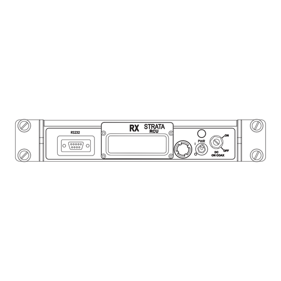
Control Switch. Status LED Information on settings made with the RX Configurator software Alphanumeric Display can be found in the Strata RX Technical Reference Manual, in Control Switch the “Advanced Operation” chapter. Using the Strata RX Screens... -
Page 30: Status Led
The RXU and RCU each have a two-line by 12-character alphanumeric display. The display works in concert with the Control Switch to allow you to monitor system status, and to control system settings. See Figure 3-2 on page 3-5. Strata RX Operator’s Guide/Tech Ref Manual Routine Operation... -
Page 31: Using The Strata Rx Screens
Using the Strata RX Screens Pushing the Control Switch in causes an action to occur. As you use your Strata RX, you will interact extensively with the screens and menus. Following are some points to make this Command Screens easier. -
Page 32: Dc On Coax Switch
Screen Lock Some Monitor Screens display readings that you may wish to monitor continuously, such as the Bit Error Ratio The Strata RX gives you two ways to control this DC power on (BER). To do this, scroll to the Monitor Screen you want to the coax cable: observe, then push the Control Switch. - Page 33 Figure 3-2: Front view - RXU and RCU STRATA STRATA ON COAX ON COAX Power DC On Coax Status Control Display Switch Switch Switch STRATA STRATA PWR/RS-485 AUDIO SIGNAL OUTPUT Strata RX Operator’s Guide/Tech Ref Manual Routine Operation...
-
Page 34: Preparing For Operation
Portable Deployment For portable applications where the Release. Strata RX will be moved from place to place and set up each time, the RX will usually be mounted in a Vislink Universal Mounting Bracket. The Bracket will then be attached to a Quick Release for easy mounting on a Vislink tripod. - Page 35 Figure 3-5: Attaching Quick Release to Tripod Mounting to the Tripod Following are the general steps to mount a Strata RX to a Vislink Tripod. These steps assume the Quick Release RX is already assembled into its Bracket, and that the Mounting Plate and Quick Release are attached.
-
Page 36: Turning The Power On And Off
The RX System will typically power up using the last settings in use when power was turned off. If the Strata RX does not power up normally, refer to the “Troubleshooting” chapter. To turn power off, flip the Power switch to the “OFF”... -
Page 37: Monitoring Operation
In Ext IF mode, the Monitor Screens that report on demodulation parameters of the incoming signal. functions are all turned off, since there is no demodulation Strata RX Operator’s Guide/Tech Ref Manual Routine Operation... -
Page 38: Using The Monitor Screens In Digital Mode
Settings are: Preset Band, Channel, Frequency COFDM Bandwidth IF Filter Color Bar Measurements are made by the RX on the incoming • signal, and consist of: Received Carrier Level Strata RX Operator’s Guide/Tech Ref Manual Routine Operation 3-10... - Page 39 Video Mute Status (ON/OFF) Vid Mute OFF Audio Aud De-emph Emphasis 1/2 1:ON 2:ON Audio Channel De-Emphasis (ON/OFF) Audio Aud De-emph Emphasis 3/4 3:ON 4:ON Error Code(s) Currently Active Error Code E154 Strata RX Operator’s Guide/Tech Ref Manual Routine Operation 3-11...
- Page 40 Aud B Lock Audio B Audio Data Status (Lock/Unlock) Analog Mono Audio Type (Analog/Digital, Stereo/Mono) Color ClrBar OFF Color Bar Generator Setting (ON/OFF) Error No Errors Error Code(s) Currently Active Code Strata RX Operator’s Guide/Tech Ref Manual Routine Operation 3-12...
-
Page 41: Monitoring Link Quality (Lq)
“falling off a cliff”. 1 - 3 Unsatisfactory Link Quality - COFDM link is not Link Quality Vislink has developed the Link Quality indicator locked. to give you back that ‘early warning’ of an analog system. Link No signal detected. -
Page 42: Lq Action Levels
Table 3-2 describes the actions we recommend at various LQ No signal: Check channel and frequency - be sure levels. These are a good initial guide; you should adjust what they match the transmitted signal. Strata RX Operator’s Guide/Tech Ref Manual Routine Operation 3-14... - Page 43 See Table 3-3. Note - Factory default settings are highlighted in green. The receiver will automatically adjust for the new settings. Note - BW must be manually set to match the transmitter. Strata RX Operator’s Guide/Tech Ref Manual Routine Operation 3-15...
-
Page 44: Monitoring Bit Error Ratio (Ber)
POST 0.0E-7 PRE 2.0E-7 POST 0.0E-7 Using BER BER is one of the key components in Vislink’s Link Quality indicator. It also can be used on its own to help alert the Note - The BER will update more slowly operator to deteriorating signal quality. -
Page 45: Monitoring Signal-To-Noise Ratio (Snr)
Start at the Main Screen. Preset #3 -43.2 dBm Turn the Control Switch RIGHT until the display shows the SNR Monitor Screen. It will be similar to this: SNR 20.78 dB IF Filter Dig Strata RX Operator’s Guide/Tech Ref Manual Routine Operation 3-17... -
Page 46: Changing Settings
Changing Settings 3.5.1 Selecting a Preset The Strata RX is designed to enable you to control operating This section describes how to configure your Strata RX with settings (through Presets) independently of your selection of different settings, using the front panel Control Switch. - Page 47 Turn the Control Switch LEFT until the desired Preset is displayed. Push the Control Switch to select that Preset. Display changes back to the Main Screen. Newly selected Preset should appear. Preset -41.7 dBm Preset Strata RX Operator’s Guide/Tech Ref Manual Routine Operation 3-19...
-
Page 48: Selecting A Channel
Push the Control Switch to select Set Channel. The current For each band installed, the Strata RX can be preconfigured for channel setting begins to blink. operation on any of up to 14 Channels, with (+), (++), and (-) offsets (depending on band). -
Page 49: Selecting A Band
Selecting a Band Turn the Control Switch LEFT until the display reads The Strata RX can be equipped to operate on two different Set RF Band. bands, designated as “High Band” and “Low Band”. The assignment of “High Band” and “Low Band” to RF hardware... -
Page 50: Selecting The If Filter
Selecting the IF Filter Display indicates the new setting, then changes back to the Main The Strata RX provides two switchable IF Filters, one optimized Screen after the default delay. for analog operation and one for digital. These switchable filters are located with the RF/IF circuitry in the RXU. -
Page 51: Setting The Monitor Output
To select the Monitor output, follow these steps: Be sure Strata is connected and powered. See “Setting Up” and “Turning the power ON and OFF”. Start at the Main Screen. Preset #3 -43.2 dBm Strata RX Operator’s Guide/Tech Ref Manual Routine Operation 3-23... -
Page 52: Setting The Squelch Level
Start at the Main Screen. Preset #3 -43.2 dBm Turn the Control Switch LEFT until the display reads Squelch Adj. Push the Control Switch to select Squelch Adj. The current Squelch setting begins to blink. Strata RX Operator’s Guide/Tech Ref Manual Routine Operation 3-24... -
Page 53: Setting The Cofdm Bandwidth
Set OFDM BW. The current Bandwidth setting begins to blink. Turn the Control Switch LEFT until the desired Bandwidth is displayed. The choices are: • 6 MHz • 7 MHz • 8 MHz Strata RX Operator’s Guide/Tech Ref Manual Routine Operation 3-25... -
Page 54: Controlling Dc Power On Coax
The System must be configured to have DC on the coax, using the DC Power Command Screen. See Section 3.5.8 In the Strata RX System, DC power is always supplied to the on page 3-26. front panel Power connector on the RCU. -
Page 55: Front Panel Menu Maps
Following are one-page menu maps to help you navigate through the settings available using the front panel Control Switch. For information on settings available when using the Strata RX Configurator, see the Strata RX Technical Reference Manual. Strata RX Operator’s Guide/Tech Ref Manual... - Page 56 Audio Aud De-emph Audio B Aud B Lock Emphasis 1/2 1:ON 2:ON Analog Mono Audio Color Aud De-emph ClrBar OFF Emphasis 3/4 3:ON 4:ON Error Error Code E154 No Errors Code Strata RX Operator’s Guide/Tech Ref Manual Routine Operation 3-28...
- Page 57 Set OFDM BW (Digital 6, 7, 8 MHz 8 MHz only) 75 Ohm Coax Power 75 Ohm Coax Power DC Power WARNING Turn off DC Power on Coax BEFORE connecting test equipment Strata RX Operator’s Guide/Tech Ref Manual Routine Operation 3-29...
-
Page 58: Front Panel Vs. Configurator Settings
IF Filter in use • Analog • Digital Squelch level • No Squelch • -65, -66, - 67,... -94, - 95 dBm • Force Squelch Signal in use for • Monitor jack • Strata RX Operator’s Guide/Tech Ref Manual Routine Operation 3-30... - Page 59 “High” and band config BISS (Encryption) • “Low” only. DC Power • DC On Coax • • COFDM COFDM Bandwidth • 6 MHz • 7 MHz • 8 MHz Strata RX Operator’s Guide/Tech Ref Manual Routine Operation 3-31...
- Page 60 7500 kHz • 8065 kHz • 8300 kHz • 8590 kHz Audio Channel Enabled • Selected • Not selected Deemphasis • Selected • Not selected Filtered • Selected • Not selected Strata RX Operator’s Guide/Tech Ref Manual Routine Operation 3-32...
-
Page 61: Troubleshooting
Above the Power Switch on both the RCU and RXU is a multi- color status LED. The LED indications are described in Chapter Overview Table 4-1. This chapter describes how to troubleshoot your Strata RX. Table 4-1: Status LED Indications Here are the topics covered: Meaning... -
Page 62: Messages On Display
One of the ways the RX will alert you to problems is by messages on its front panel display. These are displayed on the Monitor Screens. See Table 4-2 for descriptions of the messages and what to do when they appear. Strata RX Operator’s Guide/Tech Ref Manual Troubleshooting... - Page 63 VIDEO • Check connection between antenna UNLOCKED and RXU. AUDIO • Check connection between RXU and RCU. UNLOCKED • Take actions to optimize RCL, SNR, and BER. See Section 3.4.6 on page 3- Strata RX Operator’s Guide/Tech Ref Manual Troubleshooting...
-
Page 64: Error Codes
Error Codes Figure 4-1: Error Code Format The Strata RX has an extensive library of diagnostic Error Codes Primary Error Code to help you pinpoint any problems. Identifies error condition. These Error Codes: See Section 4.4.1 on page 4-4. •... - Page 65 Subcarrier frequencies must match Detected frequencies must match transmitter. incoming signal. E207 FMR Audio 4 No Sub-Carrier • Call for technical service. • If problem persists, possible Detected hardware failure. Send unit for service. Strata RX Operator’s Guide/Tech Ref Manual Troubleshooting...
- Page 66 E151 RXU 5.5 volt line error Correct power problem. failure. Send unit for service. E152 RXU +12 volt line error • Call for technical service. E153 RXU -12 volt line error Strata RX Operator’s Guide/Tech Ref Manual Troubleshooting...
- Page 67 Send unit for service. • Check to be sure RX has room around it for air circulation. Move objects preventing air flow. • Call for technical service. Strata RX Operator’s Guide/Tech Ref Manual Troubleshooting...
- Page 68 Correct power problem. failure. Send unit for service. E1F2 RCU +12 volt line error • Make sure all power cables are E1F3 RCU -12 volt line error connected properly. • Call for technical service. Strata RX Operator’s Guide/Tech Ref Manual Troubleshooting...
- Page 69 Send unit for service. E1F9 RCU Circular Connector Voltage error • Call for technical service. E1FA RCU Circular Connector Power error Strata RX Operator’s Guide/Tech Ref Manual Troubleshooting...
-
Page 70: Error Status
The Unit ID digit identifies which part of the RX System is reporting a problem. See Table 4-5. Table 4-5: Strata Unit ID Digit Unit ID Transmitter Unit (TXU) Receiver Unit (RXU) Receiver Control Unit (RCU) Strata RX Operator’s Guide/Tech Ref Manual Troubleshooting 4-10... - Page 71 Screens. Specifically check Video Deviation. Settings must match transmitter settings. Video signal level too high Check video signal - should be 1 V p-p. at transmitter. Strata RX Operator’s Guide/Tech Ref Manual Troubleshooting 4-11...
- Page 72 Suggested Technical Staff Action If Unit Enabled for Optional BISS Encryption/Decryption No video. BISS Decryption not Use Configurator to check BISS settings. Be sure operating. key and/or ID match the transmitter settings. Strata RX Operator’s Guide/Tech Ref Manual Troubleshooting 4-12...
- Page 73 Use Configurator to check settings. Be sure all settings of RX do not match Monitor Screens and Command settings match the transmitter settings. settings of transmitter. Screens. Channel, Offset, and Frequency must match transmitter. Strata RX Operator’s Guide/Tech Ref Manual Troubleshooting 4-13...
- Page 74 If Unit Enabled for Optional BISS Encryption/Decryption No audio in one or BISS Decryption not Use Configurator to check BISS settings. Be sure more channels. operating. key and/or ID match the transmitter settings. Strata RX Operator’s Guide/Tech Ref Manual Troubleshooting 4-14...
- Page 75 Contact Vislink for latest information on select Service Name support Service Name availability. and Service Number. functionality. Unable to manually RX does not currently Contact Vislink for latest information on select PIDs. support selecting PID availability. values. Strata RX Operator’s Guide/Tech Ref Manual Troubleshooting 4-15...
- Page 76 Suggested Technical Staff Action PID values reported on RX does not currently Contact Vislink for latest information on Monitor Page of support multi-service availability. Configurator are selection. PID values incorrect. shown are fixed. Strata RX Operator’s Guide/Tech Ref Manual Troubleshooting 4-16...
-
Page 77: Advanced Operation
The procedures described in this chapter will assume you This chapter describe how to use the Strata RX Configurator already know how to operate your Strata RX System. If this is not software to configure settings in the Strata RX. This is the case, please review the information presented in the information that would be useful to technical staff. -
Page 78: System Rules
5.2.4 System Rules modify it. See Section 5.3.2 on page 5-4. When configuring your Strata RX System, the following system rules must be followed. • Load in an existing configuration from the RX and • An RXU can contain either an analog demodulator (FMR) modify it. - Page 79 RC Front Panel blocks. Also click on any other blocks you wish to configure. See Figure 5-3 for an example of an RCU-only configuration. Select each Tab and make your choices for Strata RX Technical Reference Manual Advanced Operation...
-
Page 80: Loading A Configuration From A File
You do not have to be connected to the RX to do this. Follow the steps below. Start the RX Configurator. Double-click the icon on your PC’s Desktop. The Main Page appears (see Figure 5-5). Strata RX Technical Reference Manual Advanced Operation... - Page 81 Select each Tab and make your choices for settings on that Page. See Figure 5-4 for an example of a configuration containing both an RXU and an RCU. See Appendix C for details of the choices on each page. Strata RX Technical Reference Manual Advanced Operation...
-
Page 82: Loading A Configuration From The Rx
Connect power through the front panel connector Click on the Connect to Radio button. on the RXU (and RCU). This will establish communication with the Strata RX. See Figure 5-7. c. Connect the RS-232 cable to the RS-232 The Connect to Radio button will change its label to connector on the RXU (or RCU if present). - Page 83 Thus it will not automatically detect the hardware change and you will not be able to configure the new hardware. Click on the Load Settings from Radio button. Strata RX Technical Reference Manual Advanced Operation...
-
Page 84: Saving The Configuration To A File
This can be on your PC’s C: drive, or on any drive you settings on that Page. choose. The default directory is “My Documents”. Type the file name in the File Name box. See Figure 5-10 for an example of a configuration Strata RX Technical Reference Manual Advanced Operation... - Page 85 Keep in mind that different versions of Windows have different rules for naming files. Click Save. Figure 5-11: Saving a Configuration to File Strata RX Technical Reference Manual Advanced Operation...
-
Page 86: Programming The Configuration Into The Rx
5-4. cable to one of them. Click on the Connect to Radio button. This will establish communication with the Strata RX. Power up both the RXU and RCU. See Figure 5-12. The Connect to Radio button will change its label to Start the RX Configurator. - Page 87 Click on the Program Radio button. The Radio/File Progress Bar appears to indicate the programming progress. The button label changes to Programming. See Figure 5-15. The programming of settings into the RX is complete Strata RX Technical Reference Manual Advanced Operation 5-11...
- Page 88 Progress Bar disappears and the button changes back to Program Radio. Figure 5-15: Programming Settings Into RXU + RCU Strata RX Technical Reference Manual Advanced Operation 5-12...
-
Page 89: Monitoring The Radio
Monitoring the Radio Figure 5-16: Main Page - No Radio Connected One of the features of the Strata RX Configurator is that it enables you to monitor the operation of your RX System, in near- real time, from your PC. In addition, you can save the monitored information to a log file for review later. -
Page 90: Viewing The Monitoring Page
RX can re-establish lock. The Configurator does not keep checking the Chroma Setting The Strata RX will automatically detect the hardware after the connection is made. Thus it will Chroma setting of the incoming signal and set up the receiver to not automatically detect the hardware change and match this setting. -
Page 91: Using The Monitoring Page
On the Monitoring Page, click the drop down arrow to the right of the Preset Window (next to the Recall Preset button). Select the Preset. Click on the desired Preset in the drop down list. Click on Recall Preset. Strata RX Technical Reference Manual Advanced Operation 5-15... - Page 92 HH = hours (in 24 hour format, e.g., 2:00 PM = 14) MM = minutes (e.g., 45) A log file created on April 27, 2004 at 1:32 PM would be named: Log20040427_1332.txt Strata RX Technical Reference Manual Advanced Operation 5-16...
- Page 93 Note that this time is taken from the PC’s internal clock, not a “Remote 1” clock in the RX. “Base 3” Channel changed from Strata RX Technical Reference Manual Advanced Operation 5-17...
-
Page 94: Front Panel Vs. Configurator Settings
IF Filter in use • Analog • Digital Squelch level • No Squelch • -65, -66, - 67,... -94, - 95 dBm • Force Squelch Signal in use for • Monitor jack • Strata RX Technical Reference Manual Advanced Operation 5-18... - Page 95 • assigned to “High” and band config BISS (Encryption) • “Low” only. DC Power • DC On Coax • • COFDM COFDM Bandwidth • 6 MHz • 7 MHz • 8 MHz Strata RX Technical Reference Manual Advanced Operation 5-19...
- Page 96 • 7500 kHz • 8065 kHz • 8300 kHz • 8590 kHz Audio Channel Enabled • Selected • Not selected Deemphasis • Selected • Not selected Filtered • Selected • Not selected Strata RX Technical Reference Manual Advanced Operation 5-20...
-
Page 97: Installation
• Verify that the items shipped agree with those listed on the sales order. This chapter describes how to unpack and install your Strata RX. • DO NOT discard the container or packing material until The topics covered in this chapter are listed below. -
Page 98: Mounting And Cabling
RX is usually bolted in place, and the cabling is permanently installed. Power comes from aircraft (or vehicle) power. Vislink Communications Ltd. US Support Centre Mounting The Strata RX is typically mounted on a bulkhead or Business Hours: Monday on the floor of a compartment using a Vislink Fixed Mounting 8:00 AM - 5:00PM Eastern Time (US) Bracket. -
Page 99: Tripod Deployment
• Secure the cabling at close intervals along its entire length. For portable applications, the Strata RX will typically be moved • Protect the cabling with additional sheathing or padding from place to place and set up each time. Most of the anywhere it passes through a hole or lays against an installation’s mounting and cabling remains in place from one... -
Page 100: Power Connections
RX and its Fixed Mounting 6.6.1 Power Requirements Bracket to a Vislink Tripod, the Bracket will attach directly to the The Strata RXU and RCU have the following power Quick Release. See Figure 6-3. - Page 101 RCU via the coaxial cable between the units. See Figure 6-5. Description: 8-pin female, cable-mount. See Figure 6-6 for pin designations on the panel connector. The mating connector is shown in Figure 6-7. See Table 6-1 for connections. Strata RX Technical Reference Manual Installation...
-
Page 102: Additional Powering Notes
Power Supply. It is available in two lengths. One cable is provided with each Strata ACU ordered. The Vislink part numbers for this cable are 907481-1 (3’ / 1 m) and 907481-2 (10’ / 3 m). It comes complete with 8-pin connectors wired on each end. -
Page 103: Grounding
Audio Connections CAUTION Power supply cords and cables must be The Strata RX can provide Analog Audio Output or Digital protected. Do not run cords where they can Audio Output, depending on how the RX is configured. All audio be walked upon. Protect cables against outputs appear on the same panel connector. -
Page 104: Analog Audio Output
Analog Mode In Analog Mode, the RX routes the received ordered. analog signal through its analog FM demodulator. The RX’s Should you need additional cables, the Vislink part number for audio switching circuitry connects the output of the FM this cable is 907471-1. - Page 105 Controlled by “Audio B” in Right (live) Screens. Configurator, displayed as “Audio B” in Monitor Left (return) Controlled by “Audio 4” in Screens. Configurator, displayed as Ground Audio 4 “Audio 4” in Monitor Left (live) Screens. Strata RX Technical Reference Manual Installation...
-
Page 106: Digital Audio Output (Aes/Ebu)
RX ordered. In Digital Mode, the RX receives a digital signal and routes the Should you need additional cables, the Vislink part number for data to the COFDM demodulator and then to the MPEG decoder. - Page 107 Contains digital Audio B. Ground Audio 3 Controlled by “Audio B” in Channel 2 - Configurator, displayed as “Audio B” in Monitor Channel 1 + Contains digital Audio A. Screens. Ground Audio 4 Channel 1 - Strata RX Technical Reference Manual Installation 6-11...
-
Page 108: Signal Connections
RXU the RS-232 connector is on the rear panel; on the RCU it is on the front panel. These female DB-9 connectors are used for three purposes: Table 6-4: Signal Connections • Remote Control using the Strata RX Remote Control Function Connector Notes Panel. -
Page 109: Wayside Data
RX to your PC. One cable is supplied with each RX ordered. Additional cables can be purchased from Vislink (part number 56500-108) or at any computer or electronics store. 5 4 3 2 1 Radio Programming and Monitoring connections are shown in Table 6-5 and Figure 6-12. -
Page 110: Multipurpose Data Cable
DTE device or a DCE device. 6.10.6 Networking The RS-232 port on the Strata RX can also be connected to a network if desired. This allows both monitoring and programming the Strata RX from a remote location. - Page 111 Wayside data from external device - not used Receive Wayside Data Figure 6-13: Multipurpose Radio and Wayside Data Cable Cable-mount Cable-mount DB9 Male DB9 Female Radio Data To Radio RS-232 Panel Connector Wayside Data Cable-mount DB9 Female Strata RX Technical Reference Manual Installation 6-15...
- Page 112 Figure 6-14: Multipurpose Radio and Wayside Data Cable RADIO (M) RADIO (M) RADIO/ RADIO/ WAYSIDE (F) WAYSIDE (F) WAYSIDE (F) WAYSIDE (F) RADIO (M) RADIO (M) RADIO/WAYSIDE RADIO/WAYSIDE WAYSIDE (F) WAYSIDE (F) Strata RX Technical Reference Manual Installation 6-16...
-
Page 113: Powering Up
Note that if you modify a product without authorization from Vislink, it may void the warranty. 6.11.2 Initial power-up For a complete Warranty statement, refer to the Notices section at the front of this manual. - Page 114 Strata RX Technical Reference Manual Installation 6-18...
-
Page 115: Repair
Vislink factory or an authorized repair depot. (0800 - 1900 hrs US ET) Supported Repairs Telephone: 800-490-5700 978-671-5700 The Strata RX System (including the RXU and RCU) is designed Fax: 978-671-5800 to be compact, rugged and reliable. Email: support@mrcbroadcast.com... - Page 116 Strata RX Technical Reference Manual Repair...
-
Page 117: Replacement Parts
907854-1 Connects RS-232 port on Cable RX to PC. For both The external cables for the Strata RX are listed in Table 8-1. If Programming and you need something that is not listed, ask your Sales Monitoring Data, and Representative or consult the factory. -
Page 118: Mounting Hardware
Mounting Hardware The mounting hardware for the Strata RX is listed inTable 8-2. If you need something that is not listed, ask your Sales Representative or consult the factory. Table 8-2: Strata RX Mounting Hardware Description Part Number Comments Antenna Lock Plate... -
Page 119: Theory Of Operation
Theory of Operation The main Strata RX functional groups are shown in Figure 9-1. They are: • RF Front End Chapter Overview Low Noise Block Down-Converter Low Noise Converter This chapter provides technical details about the design and • AGC/IF functioning of the Strata RX. - Page 120 Figure 9-1: Strata RX System Architecture RF Front End Demodulation and Decoding Switched Outputs - IF/Video/Audio Low Noise Low Noise Block Down Converter (LNC) Converter (LNB) AGC/IF Switch COFDM MPEG Decoder Demodulator Interface 900 MHz MON. 70 MHz 2 GHz...
-
Page 121: Rf Front End
Mixer. frequency using a crystal-controlled digital synthesizer. The base Mixer In the Mixer, the incoming signal is mixed with the LO frequency is set by the crystal, and the synthesizer allows the Strata RX Technical Reference Manual Theory of Operation... -
Page 122: Band-Specific Rf Architecture
LNC. These special LNBs therefore would accept the RF signal and convert it directly to 900 MHz. No other modules are needed in the Front End. See Figure 9-2. See Figure 9-4. Strata RX Technical Reference Manual Theory of Operation... - Page 123 AUX Input of the 2 GHz LNC, which converts it to 900 MHz. When operated in the 2 GHz band, the LNB is bypassed and the 2 GHz RF signal is coupled directly into the RF Input of the 2 GHz LNC. Strata RX Technical Reference Manual Theory of Operation...
- Page 124 Figure 9-6: Low Noise Block Down Converter (LNB) 2 GHz LOW NOISE CONVERTER LOW PASS LOW NOISE (LNC) MIXER AMPLIFIER FILTER AMPLIFIER (LNA) INPUT 900 MHz 2 GHz BAND PASS LOCAL AMPLIFIER MULTIPLIER FILTER OSCILLATOR Strata RX Technical Reference Manual Theory of Operation...
- Page 125 Figure 9-7: Band Switched LNB 2 GHz LOW NOISE CONVERTER LOW PASS (LNC) LOW NOISE FILTER AMPLIFIER MIXER AMPLIFIER (LNA) INPUT BAND PASS FILTER 900 MHz 2 GHz BAND PASS LOCAL AMPLIFIER MULTIPLIER FILTER OSCILLATOR Strata RX Technical Reference Manual Theory of Operation...
- Page 126 Figure 9-8: Low Noise Converter (LNC) LOW PASS MIXER AMPLIFIER FILTER LOW NOISE AMPLIFIER (LNA) INPUT 900 MHz BAND PASS LOCAL AMPLIFIER MULTIPLIER FILTER OSCILLATOR Strata RX Technical Reference Manual Theory of Operation...
- Page 127 Figure 9-9: 2 GHz Low Noise Converter (LNC) LOW NOISE AMPLIFIER (LNA) INPUT LOW PASS LOW PASS MIXER AMPLIFIER FILTER FILTER 900 MHz INPUT LOW PASS FILTER LOCAL BAND PASS AMPLIFIER MULTIPLIER OSCILLATOR FILTER Strata RX Technical Reference Manual Theory of Operation...
-
Page 128: Agc/If Module
Provides receiver squelch control in IF and Analog modes. Switch and IF Interface Module The Strata RX provides a very high degree of operator control over inputs and outputs. All of this flexibility is managed by the Monitor Signal Out Switch and IF Interface Module. - Page 129 Monitor Genlock IF Interface Audio Out IF Switching/Logic Circuit IF In Audio C Video Audio C Video F Sync IF In COFDM FM Receiver MPEG Decoder Demod ASI Out ASI In Strata RX Technical Reference Manual Theory of Operation 9-11...
-
Page 130: Audio Switching
Analog Audio Aud A audio Outputs Note that when the Strata RX RCU or RXU is operated in the MPEG DECODER digital mode, the MPEG decoder audio outputs may be configured for analog or digital audio outputs as shown in Figure 9-13. -
Page 131: Demodulation And Decoding
RCU and/or RXU The Command and Control circuits handle communications front panel displays, or by connecting a PC to the Strata RX RS- between the RXU and RCU, and between the RX and external 232 serial port and running the Strata RX Configurator utility. - Page 132 RX system from either unit’s front panel. It also permits controlling the entire system from either unit’s RS-232 connector, using the RX Configurator software. Strata RX Technical Reference Manual Theory of Operation 9-14...
-
Page 133: Channels & Frequencies
Channels & Initial Factory Presets Frequencies This section lists the channels and frequencies for each RF band covered by the Strata RX. These frequencies are preset at the factory, but can be modified using the Strata RX configurator software. Appendix Overview... - Page 134 (++) Offset (MHz) 1994.750 1999.000 2003.250 2012.250 2016.500 2020.750 2029.250 2033.500 2037.750 2046.250 2050.500 2054.750 2063.250 2067.500 2071.750 2080.250 2084.500 2088.750 2097.250 2101.500 2105.750 2454.250 2458.500 2462.750 2471.250 2475.500 2479.750 2487.750 2492.000 2496.250 Strata RX Operator’s Guide/Tech Ref Manual Channels & Frequencies...
- Page 135 (++) Offset (MHz) 2300.000 2313.333 2326.666 2339.999 2353.332 2366.665 2379.998 2393.331 2406.664 2419.997 2433.330 2446.663 2459.996 2473.329 2486.662 2499.995 2513.328 2526.661 2539.994 2553.327 2566.660 2579.993 2593.326 2606.659 2619.992 2633.325 2646.658 2659.991 2673.324 2686.657 Strata RX Operator’s Guide/Tech Ref Manual Channels & Frequencies...
- Page 136 3531.250 3543.750 3556.250 3568.750 3581.250 3593.750 3606.250 3610.000 3620.000 3630.000 3640.000 3650.000 3660.000 3670.000 3680.000 3690.000 3700.000 3710.000 3720.000 3730.000 3740.000 3750.000 3760.000 3770.000 3780.000 3790.000 3800.000 3800.000 3800.000 3800.000 3800.000 Strata RX Operator’s Guide/Tech Ref Manual Channels & Frequencies...
- Page 137 4725.000 4750.000 4775.000 4800.000 4825.000 4850.000 4875.000 4900.000 4925.000 4925.000 4940.500 4941.500 4942.500 4943.500 4944.500 4944.500 4947.500 4952.500 4957.500 4962.500 4967.500 4972.500 4977.500 4982.500 4982.500 4985.500 4986.500 4987.500 4988.500 4989.500 4989.500 Strata RX Operator’s Guide/Tech Ref Manual Channels & Frequencies...
- Page 138 6968.750 6981.250 6987.500 6993.750 7006.250 7012.500 7018.750 7031.250 7037.500 7043.750 7056.250 7062.500 7068.750 7081.250 7087.500 7093.750 7106.750 7112.500 7118.750 6421.250 6437.500 6443.750 6456.250 6462.500 6468.750 6481.250 6487.500 6493.750 6506.250 6512.500 6518.750 Strata RX Operator’s Guide/Tech Ref Manual Channels & Frequencies...
- Page 139 7057.135 7071.420 7085.705 7099.990 7114.275 7128.560 7142.845 7157.130 7171.415 7185.700 7199.985 7214.270 7228.555 7242.840 7257.125 7271.410 7285.695 7299.980 7314.265 7328.550 7342.835 7357.120 7371.405 7385.690 7399.975 7414.260 7428.545 7442.830 7457.115 7471.400 7485.685 Strata RX Operator’s Guide/Tech Ref Manual Channels & Frequencies...
- Page 140 7883.326 7899.992 7916.658 7933.324 7949.990 7966.656 7983.322 7999.988 8016.654 8033.320 8049.986 8066.652 8083.318 8099.984 8116.650 8133.316 8149.982 8166.648 8183.314 8199.980 8216.646 8233.312 8249.978 8266.644 8283.310 8299.976 8316.642 8333.308 8349.974 8366.640 8383.306 Strata RX Operator’s Guide/Tech Ref Manual Channels & Frequencies...
- Page 141 10183.32 10199.99 10216.65 10233.32 10249.99 10266.65 10283.32 10299.98 10316.65 10333.32 10349.98 10366.65 10383.31 10399.98 10416.65 10433.31 10449.98 10466.64 10483.31 10499.98 10516.64 10533.31 10549.97 10566.84 10583.31 10599.97 10616.64 10633.30 10649.97 10666.64 10683.30 Strata RX Operator’s Guide/Tech Ref Manual Channels & Frequencies...
- Page 142 12857.14 12870.23 12883.33 12896.42 12909.52 12922.61 12935.71 12948.80 12961.90 12974.99 12988.09 13001.18 13014.28 13027.37 13040.47 13053.56 13066.66 13079.75 13092.85 13105.94 13119.04 13132.13 13145.23 13158.32 13717.42 13184.51 13197.61 13210.70 13223.80 13236.89 Strata RX Operator’s Guide/Tech Ref Manual Channels & Frequencies A-10...
-
Page 143: Us 2 Ghz Reallocation - 12 Mhz Channel Plan
US 2 GHz Reallocation - 12 MHz Channel Plan Here are the frequencies that will be used on the 2 GHz band in the new US 12 MHz channel plan. Your Strata RX is pre-programmed with the frequencies listed in Section A.2 on page A-1. However, as your station migrates to the new channel plan, you can easily reprogram your Strata RX using the Strata RX configurator software. - Page 144 Strata RX Operator’s Guide/Tech Ref Manual Channels & Frequencies A-12...
-
Page 145: Glossary
Table B-1: Useful Terms (Continued) Automatic Frequency Control. Automatic Gain Control. This section describes acronyms and abbreviations used in Alarm Indication Signal (all one’s). communications, broadcasting, and in Vislink Products and Alternate Mark Inversion, line code format for traffic documentation. data. Average. - Page 146 Done on the receive end of an analog link to take out Emphasis ERRS Errors. added on the transmit side. Electrostatic discharge. Discrete Fourier Transform ETSI European Telecommunications Standards Institute Strata RX Operator’s Guide/Tech Ref Manual Glossary...
- Page 147 2. A unit of measurement, established by the IRE, in OFDM Orthogonal Frequency Division Multiplexing which 1 IRE Unit =.00714 volts peak-to-peak (Vp-p) and 140 IRE units equals 1 Vp-p. ØLK Phase Lock. Strata RX Operator’s Guide/Tech Ref Manual Glossary...
- Page 148 Also called Y/C Reed-Solomon Video. Composite Video combines them into one Rx or RX Receiver. signal. S/W or SW Software. SYNTH Synthesizer Service Channel. 1.544 Mbps traffic rate. Single Carrier Transmitter. Voltage Controlled Oscillator. Strata RX Operator’s Guide/Tech Ref Manual Glossary...
- Page 149 Xmitr Transmitter. Xmtr Transmitter. Video signal in which the chrominance (color) and luminance (brightness) information are separated into separate subcarrier signals. Also called S-Video. Composite Video combines them into one signal. Strata RX Operator’s Guide/Tech Ref Manual Glossary...
- Page 150 Strata RX Operator’s Guide/Tech Ref Manual Glossary...
-
Page 151: Configurator Reference
The Strata RX Configurator is a Windows-based application that enables you to control all of the settings on the Strata RX, and tailor them exactly to your needs. Settings can be configured offline (not connected to an RX), or you can connect to the RX through an RS-232 link to make the changes. - Page 152 For example, in Figure C-1, the COFDM and encryption enabled. MPEG tabs are grey. That is because this offline configuration has no CPOFDM or MPEG selected. Figure C-2: MPEG Page with Greyed-Out Choices Figure C-1: Main Page with Greyed-Out Tabs Strata RX Technical Reference Manual Configurator Reference...
-
Page 153: Progress Bars
On the Main Page, the labelled Buttons are used to control screen. See Figure C-3. communication between your PC and the Strata RX, and to execute loading and saving settings. See Figure C-1. This Progress Bar is displayed when you are Loading or... -
Page 154: Load And Program Options
Loading or programming the entire radio is the best choice when you have many changes to make. When the changes are more limited, loading/programming a single page or a single preset will save time. Strata RX Technical Reference Manual Configurator Reference... - Page 155 Page’s settings to the radio - even if you changed settings on other Pages as well. Figure C-7: Main Page - Program an Individual Preset Figure C-6: Radio Page - Load a Single Page Strata RX Technical Reference Manual Configurator Reference...
-
Page 156: Configurator Pages
COFDM Page System. MPEG Page • Monitor the operation of the RX on your PC, and log the FMR Page C-11 monitored information to a file. Channel Plan Page C-13 Figure C-8: Main Page Strata RX Technical Reference Manual Configurator Reference... -
Page 157: Radio Page - Standard
Auto-disable When you choose the Operating Mode, the Use the Analog filter for analog operation. Configurator automatically enables or disables other Tabs, Pages, Buttons, and individual choices to correspond to that Digital Operating Mode. Strata RX Technical Reference Manual Configurator Reference... -
Page 158: Radio Page - Frequencies Locked To Presets
For some applications you may wish to have the Preset also set the Frequency. The ability to do this is a factory-enabled option that must be specified when your radio is ordered. If you have this option, your Radio Page will have two additional Strata RX Technical Reference Manual Configurator Reference... -
Page 159: Cofdm Page
Select whether the decoder adds an NTSC Pedestal to the incoming signal. Choices are: Selected (checked). The RX adds an NTSC pedestal to the signal. Not selected (unchecked). The incoming signal passes through with no Strata RX Technical Reference Manual Configurator Reference... - Page 160 Preset. If a particular Preset should not have access to Configure BISS Decryption • the encrypted information, enter an invalid key for that Preset. BISS Decryption is a factory-enabled option that must be Strata RX Technical Reference Manual Configurator Reference C-10...
-
Page 161: Fmr Page
When Connected to the RX The analog demodulator (FMR) must installed in the RXU, and there cannot be an RCU in the System. When configuring offline The FMR in the RXU must be selected and the RCU cannot be selected. Strata RX Technical Reference Manual Configurator Reference C-11... - Page 162 When selected (checked), applies filtering to the audio signal. This is a notch filter to remove the video scan rate frequency from the audio signal. When not selected (unchecked), turns filtering off. Strata RX Technical Reference Manual Configurator Reference C-12...
-
Page 163: Channel Plan Page
ì .î not ì ,î . If your computer is configured to use ì ,î as the decimal separator, see ì Configurator Troubleshootingî on page C-17. • All fields must be filled - leave no blank fields. Strata RX Technical Reference Manual Configurator Reference C-13... -
Page 164: Front Panel Vs. Configurator Settings
IF Filter in use • Analog • Digital Squelch level • No Squelch • -65, -66, - 67,... -94, - 95 dBm • Force Squelch Signal in use for • Monitor jack • Strata RX Technical Reference Manual Configurator Reference C-14... - Page 165 • assigned to “High” and band config BISS (Encryption) • “Low” only. DC Power • DC On Coax • • COFDM COFDM Bandwidth • 6 MHz • 7 MHz • 8 MHz Strata RX Technical Reference Manual Configurator Reference C-15...
- Page 166 • 7500 kHz • 8065 kHz • 8300 kHz • 8590 kHz Audio Channel Enabled • Selected • Not selected Deemphasis • Selected • Not selected Filtered • Selected • Not selected Strata RX Technical Reference Manual Configurator Reference C-16...
-
Page 167: Configurator Troubleshooting
RXU and RCU, see Chapter 4, “Troubleshooting”. C.6.1 Configurator Error Messages Table C-2: Configurator Error Messages The Strata RX Configurator has an extensive set of self- diagnostics that will alert you when an operation cannot be Suggested completed. Error Message... - Page 168 Contact MRC. File damaged. Re-create hardware defective. configuration and save it with a Unable to Open different filename. Configuration File Problem with PC or Contact your PC its disk drive. service provider. Strata RX Technical Reference Manual Configurator Reference C-18...
-
Page 169: Configurator Operational Problems
COFDM Tab is Operation Mode set On Radio Page, set selected but many incorrectly. Operation Mode for choices are greyed at least one Preset out. to MPEG CV Out, ASI Out, or SDI Out. Strata RX Technical Reference Manual Configurator Reference C-19... - Page 170 Control Panel to status and identify uninstall the which subcarriers Configurator, then not being received. reinstall it. Problem with PC or Contact your PC its disk drive. service provider. Strata RX Technical Reference Manual Configurator Reference C-20...
-
Page 171: Installing The Configurator
Configurator, simply switch back to the correct language. Locate the CD that was provided with your Strata RX. Insert the CD into your computer’s CD drive. Figure C-16: Using the “My Computer” icon on your PC (or any other method), navigate to that CD drive and display the CD’s directory on your screen. -
Page 172: Pc Requirements
PC Requirements RX System Compatibility The Strata RX Configurator is designed to run on Windows - This section will give you compatibility information for the based PCs that meet the following requirements: Cofigurator software and the RX System. For Compatibility with various PCs, see “PC Requirements”... - Page 173 Figure C-18: About Window Compare the version number in the line “For use with” to the version of your Strata RX found earlier. The version listed in the “For use with...” line is the minimum version of RX required (i.e., the RX should be that version or higher).
- Page 174 Strata RX Technical Reference Manual Configurator Reference C-24...
-
Page 175: Link Quality
Appendix Overview quality of the received signal degrades. This appendix describes Vislink’s Link Quality indicator, and how Analog Systems In traditional analog transmissions, each link it helps you maintain good quality video and audio. -
Page 176: Understanding Link Quality
Excellent Link Quality - COFDM link is very robust with ample ability to correct for degradation. Vislink has developed the Link Quality (LQ) indicator to give you back that ‘early warning’ of an analog system. Link Quality Very Good Link Quality - COFDM link is robust for monitors several key parameters and settings, and uses a the given environment. -
Page 177: Lq And Signal Quality
Moving further to the right on the graph, the Received Signal Quality continues to degrade. LQ reading starts to drop more rapidly to alert you to the impending loss of video. As loss of video gets closer, LQ drops even faster. Strata RX Technical Reference Manual Link Quality... -
Page 178: What Actions To Take
LQ begins to fall. transmitter. Optimize RCL. No signal: Check channel and frequency - be sure they match the transmitted signal. If RCL is -70 dBm or lower, the signal is weak. Strata RX Technical Reference Manual Link Quality... -
Page 179: Technical Background: Lq Factors
By contrast, an FEC setting of 7/8 would mean that every In analog systems, efforts to optimize the link quality are usually 7 packets of payload are accompanied by 1 packet of directed at improving the received signal strength (RCL), with the Strata RX Technical Reference Manual Link Quality... - Page 180 A BW setting of 8 MHz would occupy more of the RF spectrum. This has the highest data transfer rate, but is the least This setting has the highest data transfer rate, but is the Strata RX Technical Reference Manual Link Quality...
-
Page 181: Ber
If the Post-Viterbi BER becomes too large, the MPEG decoder will be unable to make sense of the data, and video will suddenly Strata RX Technical Reference Manual Link Quality... - Page 182 Strata RX Technical Reference Manual Link Quality...
-
Page 183: Index
Index US 12MHz Plan A-11 COFDM B-2 COFDM Bandwidth, Setting 3-25 COFDM UNLOCKED message 4-3 Numerics Composite (Baseband) B-2 Composite Video B-2 16QAM B-1 Connections 4FSK B-1 and Controls 2-5 64QAM B-1 Audio 2-5 GEN LOCK 2-6 ADPCM B-1 MON. (Monitor) 2-6 AES B-1 Controls AES/EBU B-1... - Page 184 DVB-T B-2 EBU B-2 Grounding 6-7 Emphasis B-2 IF Filter, Selecting 3-22 Error Codes 4-4 Indoor Unit Error Messages 4-2 See IDU Initial Inspection 6-1 For More Information 2-14 Inspection Frequencies Locked to Presets 3-20 Initial 6-1 Frequently Performed Tasks Controlling DC on Coax 3-26 Monitoring Bit Error Ratio (BER) 3-16 LEDs...
- Page 185 General System 4-15 Options Video 4-11 Antenna 2-3 Output, Monitor 3-23 Bands 2-1 Demodulator 2-1 Deployment 2-4 PAL B-4 Mounting 2-4 Power, Turning On/Off 3-8 Power 2-3 Preset RF 2-1 Selecting 3-18 System Problems 4-15 QAM B-4 TRANSPORT UNLOCKED message 4-3 QPSK B-4 Troubleshooting Error Codes 4-4...
- Page 186 CodeRunner 2 Technical Reference Manual Index...
Need help?
Do you have a question about the Strata RX and is the answer not in the manual?
Questions and answers