
Subscribe to Our Youtube Channel
Related Manuals for Vislink airstream LGR-1000


Summary of Contents for Vislink airstream LGR-1000
- Page 1 Live Gear Receiver LGR-1000 User and Technical Manual Manual Part No. RD000785 Rev. C, March, 2014...
- Page 2 Vislink. The information in this manual remains the property of Vislink and may not be used, disclosed, or reproduced in any form whatsoever, without the prior written consent of Vislink. Vislink reserves the right to make changes to equipment and specifi cations of the product described in this manual at any time without notice and without obligation to notify any person of such changes.
-
Page 3: Table Of Contents
Upgrade Software ....................21 Specifi cations...................23 Video ........................23 Audio ........................23 Controls/Displays ....................23 Physical ......................23 Environmental ....................23 Appendix A: LGR Connectors & Controls ........24 Glossary ...................25 Notes ........................27 Support for Your Vislink Product ............28 Page 3 LGR User Guide and Technical Manual... -
Page 4: Unpacking The Livegear Receiver
If you discover damage after unpacking the system, report the damage as follows: • Immediately fi le a claim with the shipping carrier. • Forward a copy of the damage report to Vislink Customer Service. • Contact Vislink Customer Service to determine the disposition of the equipment. See: Support for Your Vislink Product on the last page. -
Page 5: Introduction
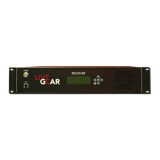
Introduction The LiveGear Receiver [LGR-1000] is a cellular Internet News Gathering [iNG] Receiver and an integral part of the AirStream transmitter systems. The LiveGear Receiver is a playout device that receives IP transmissions via the Internet and provides a HD/SD-SDI output. Up to six transmitters [future option] can be simultaneously received using one LGR receiver. -
Page 6: Features
19” rack mount unit. Plug-n-Play – Connect the LGR-1000 to an Ethernet ISP connection and instantly decode your remote transmitters. Reception Integrity – Exclusive Vislink algorithms optimize IP cellular transmission. Video Quality – Dependable forward error correction [FEC] algorithms ensure seamless decoding of the H.264 video signal. -
Page 7: Lgr Operation
LGR Operation The LiveGear Receiver features a front panel User Interface - an alphanumeric LCD menu-driven display as well as a convenient Web interface, putting the intuitive control of this device at your fi ngertips using a pc, tablet, laptop or smart phone. Refer to the fi... -
Page 8: Lgr And Airstream System Setup
LGR and AirStream System Setup This section describes how to confi gure an AirStream/LiveGear Receiver pair and begin streaming video over a cellular network as quickly as possible using the default settings. After receiving an AirStream and LGR, the fi rst device to be confi gured should be the LGR. - Page 9 Confi guration Steps [continued] On the LiveGear Receiver: a. Using the LCD on the front panel, press the up arrow to display the WAN IP address. This IP address needs to be entered in the host address fi eld using the AirStream touchscreen or Web page.
-
Page 10: Lgr Login Web Page
LGR Login Web Page Type the LGR IP address in a Web browser to display the Login Web page. The default user ID and password is admin. This page also appears when you select the Logout tab in any of the Web pages, allowing you to reenter your user name and password or login a new user. -
Page 11: Lgr Status Web Page
LGR Status Web Page The LGR Status page displays fi rst when you open the LGR Web interface. There are three sections of the Status page: Current Status, Interface Details and IFB Settings. Page 11 LGR User Guide and Technical Manual... -
Page 12: Current Status
You can also access the Status page when you click the logo in either the LGR [or AirStream] Web pages. The LGR Web pages can be accessed from a PC or laptop connected to a LAN port on the LGR-1000. The default IP address is http://192.168.2.200/. -
Page 13: Lgr Ifb Settings
LGR IFB Settings The IFB setup for the LGR include the channel being listened to and the IFB call state fi elds, as shown in the sample Web page above. Local Channel Setup Select Channel Select an open Channel from which the LGR will receive the IFB signal. The channels dedicated to IFB reception range from 1 to 6. -
Page 14: Lgr Network Settings Web Page
LGR Network Settings Web Page The LGR’s network setup page includes entry fi elds for Wide and Local Area Networks, as shown below. WAN and LAN Confi guration The Wide and Local Area Network confi guration entry fi elds include: IP Type and Address [if required], Net Mask, Gateway and DNS Server. -
Page 15: Wan Confi Guration
WAN Confi guration IP Type The Internet Protocol Type drop-down entry fi eld provides the choice of either Static or DHCP [Dynamic Host Confi guration Protocol] to confi gure the LiveGear receiver. Set your own IP address by selection of Static IP Type or change to DHCP to set the address from your DHCP server. -
Page 16: Lgr Decoder Settings Web Page
Start Address This fi eld sets the starting IP address range when the IP type is set to DHCP server mode. Maximum Clients This entry fi eld allows the selection of the maximum number of clients permitted when the DHCP server is used. The maximum entry is 50. Save Changes Be sure to click the Save Changes button to retain revisions to the Network Settings page. -
Page 17: Lgr Inputs Web Page
Decoder Resolution The Video Decoder Resolution drop-down fi eld allows the selection of the following: • 480i [NTSC] • 576i [PAL] • 720p60 • 720p59 • 720p50 • 1080i60 • 1080i59 • 1080i50 • 1080p23 • 1080p24 • 1080p25 • 1080p29 •... - Page 18 Save Changes Click Save Changes to retain your selections of LGR Inputs. Page 18 LGR User Guide and Technical Manual...
-
Page 19: Lgr Outputs
LGR Outputs LGR Outputs Web page includes LiveGear Receiver Output Information. Refer to the sample Web page shown below. LGR Outputs Enabled Click the Enabled check box to allow the output to be used. Name This fi eld displays the output name. Input Stream This fi... - Page 20 Receiver IP The receiver’s IP Address is displayed in this fi eld. Port # The output port number is displayed in this fi eld. The add output button allows you to create a new output for the LGR using the New Output dialog box shown below.
-
Page 21: Lgr Support, System And Software Upgrade Web Page
This fi eld displays a unique LGR Support Identifi cation number that you will need when communicating with Vislink support. Support Contact This fi eld displays the contact phone number for Vislink support [+1 978-671-5995 or 888-777-9221]. LGR Software Upgrade The LGR Firmware Upgrade section is a part of the Support page. - Page 22 Page 22 LGR User Guide and Technical Manual...
-
Page 23: Specifi Cations
Specifi cations Product Profi le IP Receiver Decoder 2 RU 19” wide rack mounted IP-to-SDI receiver decoder with Web browser GUI interface. Video Interfaces [input] HD/SD-SDI standard, BNC Formats HD, SD Resolutions 1080i60, 1080i59.94, 1080i60, 720p50, 720p59.94, 720p60, SD SDI [NTSC] [US] SD SDI [PAL] [EU] [Consult Factory for Other Resolutions] Decoding H.264 AVC high profi... -
Page 24: Appendix A: Lgr Connectors & Controls
Appendix A: LGR Connectors & Controls Connectors and controls are described below. Table 1: LGR-1000 Control Panel & Connections Name Connector Description Power Switch This is a momentary switch that when pressed, activates the LGR-1000 if the AC power supply switch is set to the 1 position.. LGR Front Panel Local User Interface Alphanumeric LCD menu-driven display with 6 push Display... -
Page 25: Glossary
Glossary Term Defi nition Access Point Name [APN] is a confi gurable network identifi er used by a mobile device when connecting to a GSM carrier. The carrier examines the APN identifi er to determine the network connection type for the AirStream transmitter. - Page 26 Term Defi nition SIM Card A Subscriber Identity Module or SIM is an integrated circuit that stores the International Mobile Subscriber Identity [IMSI] and key used to identify and authenticate subscribers on mobile telephony devices. A SIM card contains: • its unique serial number [ICC ID] •...
-
Page 27: Notes
Notes Page 27 LGR User Guide and Technical Manual... -
Page 28: Support For Your Vislink Product
Support for Your Vislink Product You can contact the Vislink T echnical Support staff as follows: 24-hour Worldwide Customer Support E-mail: ussupport@vislink.com T elephone: +1 978-671-5929, 978-71-5995 or 888-777-9221 In the US or Canada The following contact numbers are also available for LiveGear equipment: •...
Need help?
Do you have a question about the airstream LGR-1000 and is the answer not in the manual?
Questions and answers