
Related Manuals for Vislink HDR-5000


Summary of Contents for Vislink HDR-5000
- Page 1 HDR-5000 Six-Input Diversity Rack- Mounted HD/SD Digital Receiver User and Technical Manual Manual Part No. RD001485 Rev. 2 February 2015...
- Page 2 Vislink. The information in this manual remains the property of Vislink and may not be used, disclosed, or reproduced in any form whatsoever, without the prior written consent of Vislink. Vislink reserves the right to make changes to equipment and specifications of the product described in this manual at any time without notice and without obligation to notify any person of such changes.
-
Page 3: Table Of Contents
Front Panel Description ......................4 Rear Panel Description ......................5 Installing the HDR-5000 ........................6 Unpacking the HDR-5000 ......................6 Preparing to Install the HDR-5000 .................... 6 2.2.1 Grounding the HDR-5000 ..................... 6 2.2.3 Protecting the HDR-5000 from Moisture ..............7 2.2.4 Routing Cables ...................... - Page 4 Change Password ........................34 3.13.1 Edit Password ......................34 Troubleshooting ..........................35 Getting Support for Your HDR-5000 ..................35 Resolving Video Problems ...................... 36 Resolving Audio Problems ...................... 37 Resolving General System Problems ..................37 HDR-5000 Specifications ........................38 ...
- Page 5 Rear Panel Connectors ......................39 5.3.1 Block Downconverter (BDC) Connectors ..............39 5.3.2 ASI OUT Connectors ....................40 5.3.3 Ethernet Connector ....................40 5.3.4 AC Power Connection ....................40 Appendix 1 Specifications for the HDR-5000 ..................41 HDR-5000 User and Technical Manual...
-
Page 7: About The Hdr 5000
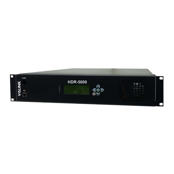
The HDR-5000 models are shown in the two figures below. The appearance of the HDR-5000-1 and -2 are the same. The HDR-5000-3 has the same features as the HDR-5000-1 and -2, except streamed video can be previewed in a screen on the right front panel of the device. -
Page 8: Hdr-5000 Features
1.1.1 Accessories The HDR-5000 receiver is compatible with several Vislink block downconverters (BDCs) that transform the incoming RF signal into UHF for input to the receiver. A typical installation consists of a receiver, low-noise block downconverters, filters, antennas and cables. -
Page 9: Front And Rear Panel Layout
HDR-5000. The HDR-5000 is typically mounted in a 19-inch (48.3 cm) rack. The unit and cabling are permanently installed and power comes from facility power. -
Page 10: Front Panel Description
Front Panel Description Figure 1-4 shows the front panel of the HDR-5000. The associated table describes the features. For more information about connector specifications, see Chapter 5, HDR-5000 Specifications. Figure 1-4. HDR-5000 Front Panel (HDR-5000-3 shown) HDR-5000 Front Panel Connections... -
Page 11: Rear Panel Description
Rear Panel Description Figure 1-5 shows the rear panel of the HDR-5000. The associated table describes the features. For more information about connector specifications, see Chapter 5, HDR-5000 Specifications. Figure 1-5. HDR-5000 Rear Panel (HDR-5000-3 shown) HDR-5000 Rear Panel Connections... -
Page 12: Installing The Hdr-5000
Installing the HDR-5000 This chapter describes how to unpack and install the HDR-5000 Six-Input Rack-Mounted HD/ SD Digital Receiver. Unpacking the HDR-5000 Before you install your new equipment, carefully unpack your new equipment to avoid accidental damage. Locate all parts and accessories and verify that they are listed on the packing list. DO NOT discard the container or packing material until you have inspected the equipment and are sure there is no shipping damage. -
Page 13: Protecting The Hdr-5000 From Moisture
Provide strain relief at each connector to absorb any pulling forces on the cable and prevent damage to the connector. If long lengths of cable are required, you may need a UHF amplifier or gain block. Contact Vislink for specific cable types and lengths to use in your application (see Section 4.1, Getting Support for Your HDR-5000). -
Page 14: Installing The Hdr-5000
Installing the HDR-5000 The HDR-5000 is typically mounted in a standard 19-inch (48.3 cm) rack. Each unit occupies 2 rack units (2RU) of height. The cabling is permanently installed and power comes from the facility or site power source. This section describes typical mounting and cabling for the HDR-5 000; your installation may vary. -
Page 15: Installing Antennas And Block Downconverters
Each low-noise block downconverter (BDC) assembly includes a block downconverter, universal pole mounting bracket and a heavy duty band clamp as shown in the figure. Vislink recommends attaching the antenna directly to the downconverter. If you do not connect the antennas directly to the downconverters, you will have to fabricate your own antenna mounting bracket. - Page 16 8. Connect each BDC to the receiver using high-quality UHF cables. 9. Repeat these steps for the next pair of antennas. Signal quality will degrade if the antennas are installed closer than the NOTE: recommended minimum separation distance. HDR-5000 User and Technical Manual...
-
Page 17: Operating The Hdr-5000
To view the current channel plan name, the channel name and frequency, press the Right Arrow button → a second time. The primary purpose of the front panel display is to view or change the HDR-5000 System ↑ Settings, use the front panel Up Arrow button to begin this process. -
Page 18: Viewing And Modifying System Settings
3.2.3 Viewing and Modifying System Settings The primary purpose of the front panel display is to view or change the HDR-5000 System Settings, ↑ especially the IP address that has been set in the factory. Use the front panel Up Arrow button display these settings. -
Page 19: Using The Web Interface
Using the Web Interface HDR-5000 remote mode of operation is supported through the Web interface. The Web interface is the primary control interface. The Web GUI will be able to: Provide current operational status of the HDR-5000 Select which type of BDC ... -
Page 20: Hdr-5000 Login Web Page
3.3.2 HDR-5000 Login Web Page Type the HDR-5000 IP address in a Web browser to display the Login Web page. The default user ID and password is root. This page also appears when you select the Logout tab in any of the Web pages, allowing you to reenter your user name and password or login a new user. -
Page 21: Unit Control Status Page (Dashboard)
3.3.3 Unit Control Status Page (Dashboard) The HDR-5000 Unit Control Status page (a.k.a. Dashboard) displays first when you type valid credentials in the Login page to access the HDR-5000 Web interface. There are nine sections for the Unit Control page shown and described below: ... -
Page 22: Network
Domain Name Server Dynamic Host Configuration Protocol Activation You are able to modify these settings for the HDR-5000 in the System Settings Web page. Select Setup and System Settings from the Dashboard menus. 3.3.9 SNR (DB) The SNR section provides a dynamic graphical display of the demodulator Signal to Noise Ratio as a function of the Received Signal Strength Indicator (RSSI) which is a measurement of the power present in a received radio signal, measured in decibels (dB). - Page 23 The Guard Interval is a method used to prevent interference within distinct transmissions The Guard Interval auto-detected by the transmitter is displayed in this field. The Guard Interval values include: 1/32 1/16 HDR-5000 User and Technical Manual...
-
Page 24: Tsoip 1 And 2 Configuration
The Transport Stream over Internet Protocol (TSoIP) sets the destination of the video signal across the IP network and the HDR-5000 is set to convert ASI to IP, HDR-5000 then streams over IP to the defined IP Address and Port. The primary and the secondary TSoIP settings that you can view are as... -
Page 25: Parameters
When you first start the process of initializing your HDR-5000, you should create Channel Plans, BDCs, TSoIP Endpoints, System Settings and if needed, Encryption Keys. Once you have created these custom parameters, add Presets that you can use and modify to receive high quality video and audio feed from your transmitters. -
Page 26: Bdc
Restore Factory Defaults button, to modify a preset with those parameter values set by the firmware. You may also choose Delete to remove a preset or Save Changes, to retain the settings for a new or modified preset. HDR-5000 User and Technical Manual... -
Page 27: Factory Restore
If the user confirms, the HDR-5000 will drop all preset and other customized settings on the receiver and return to the factory defaults. -
Page 28: Channel Plans
You are able to hide a channel plan using the Hide button. The HDR-5000 system allows selection of 1 of 4 frequency ranges (S, C2, or C4). Each frequency range is coupled to work with a single BDC type and each frequency range will have its own default Channel Plan. - Page 29 The lower section provides a means to create AES and Bcrypt encryption keys within the Add Encryption Keys section. After you create a key, you must click the Save Changes button to add it to the HDR-5000 system. To delete existing Encryption Keys, use the button in the Remove Encryption Keys listing of all the existing keys.
-
Page 30: Steps To Create A New Encryption Key
The Advanced Encryption Standard (AES) is a specification for encryption of electronic data established by NIST. A Bcrypt decryption module allows the HDR-5000 to interoperate with any COFDM streams using standardized encryption. Within the Parameters section you can change the Decryption setting to allow encrypted packets to go through the system, when you select Pass Through option in the TSoIP drop-down. -
Page 31: Edit Encryption Definition
3.7.5 Add Encryption Keys When you add an encryption key, type a Name and Key within the Add Encryption Keys entry fields. Select a Mode from the drop-down menu. Click Save Changes to add the new Encryption Key. HDR-5000 User and Technical Manual... -
Page 32: Tsoip Endpoint
The Transport Stream over Internet Protocol (TSoIP) sets the destination of the video signal across the IP network and the HDR-5000 will stream Video over IP based on its settings. The TSoIP settings that you can control are as follows: ... -
Page 33: System Settings
IP Address The Internet Protocol Address that is used by the HDR-5000 receiver can be modified by not selecting the DHCP Enable feature. Click within the field and type the value of the address that you want to modify. -
Page 34: Support
Network (LAN or WAN) used to send packets from the LAN. The Gateway Address that is displayed for the HDR-5000 can be modified, when DHCP Enable is not selected. Click within the address field and type the value of the address that you want to modify or enter. Modify the Gateway address to match settings provided by your network administrator. -
Page 35: System Details
Periodically we release updates and recommend that you install these. You can download these updates at our FTP site. To access the FTP site: 1. Go to http://www.vislink.com/support/. 2. Scroll down to the Downloads section, and click the Vislink FTP link. The FTP site displays in your web browser. HDR-5000 User and Technical Manual... - Page 36 3. Click the MRC Products folder to display its contents. 4. Scroll down to the HDR-5000 folder, and click on it. Look for the latest firmware file, which has the .deb extension. Click on this file to download it, and note where you saved it on your computer.
- Page 37 6. Click the Choose File Upgrade button to open Windows Explorer, and select the firmware file you downloaded from Vislink’s FTP site. 7. The following message displays on the Upgrade System Software page as the firmware is updated on your HDR-5000 device:...
- Page 38 8. When the firmware update is finished, the login screen displays. Log in again by entering your username and password, and clicking the Log In button. HDR-5000 User and Technical Manual...
-
Page 39: User Management
3.12 User Management The User Management Web page provides a means to edit, create or delete HDR-5000 users. The Information section also displays the fields that can be used to revise or create credentials for each HDR- 5000 user. To display this page, click on the down arrow displayed in the upper right hand corner of the Web interface (adjacent to the current user name) and select Manage Users. -
Page 40: Change Password
1. Old Password: First type the old password. 2. New Password: Next, type the new password. 3. Repeat New Password: Finally, re-enter the new password for confirmation and click the Change Password button to finish the process. HDR-5000 User and Technical Manual... -
Page 41: Troubleshooting
Firmware revisions of the options contained in your receiver. You can obtain these as follows: 1. Select Support on the Web Dashboard page. 2. The Support page lists installed hardware and software components and revision levels. There are no supported field repairs to the HDR-5000 system. Return the unit for NOTE: factory repair. -
Page 42: Resolving Video Problems
Verify the connections between No SNR camera and transmitter. Make sure the bandwidth (BW) is on the correct setting. See Section 3.3.5, Channel. HDR-5000 User and Technical Manual... -
Page 43: Resolving Audio Problems
Remove the top cover and check the power supply fuses with the power cable disconnected. Upon confirmation of functional fuses, reconnect power cable. S t th it h t ON HDR-5000 User and Technical Manual... -
Page 44: Hdr-5000 Specifications
This appendix contains connector specifications for your HDR-5000 Six-Input Rack-Mounted HD/SD Digital Receiver. HDR-5000 Dimensions The following figure shows the HDR-5000 dimensions in inches (16.972" x12.031" x 3.490"). Figure 5-1. Dimensions of the HDR-5000 in Inches HDR-5000 User and Technical Manual... -
Page 45: Front Panel Connectors
Front Panel Connectors The following sections describe the HDR-5000 front panel connectors. Figure 1-4 shows the front panel connectors. 5.2.1 USB Connectors The following table shows pin-out information for the USB 2.0 connector. Connector Pinout Name Signal Description +5 VDC... -
Page 46: Asi Out Connectors
The power supply accepts a range of AC input voltages from 105–240 VAC at 50–60 Hz. The power supply provides the DC voltages required by the rest of the receiver’s hardware. Typical output voltages are +24 VDC, +5 VDC, +12 VDC, and -12 VDC. HDR-5000 User and Technical Manual... -
Page 47: Appendix 1 Specifications For The Hdr-5000
Appendix 1 Specifications for the HDR-5000 GENERAL POWER: Diversity: Six-Input MaxRC AC Power Input: COFDM Bandwidth Support: ■ 120-240 VAC, 50/60 Hz ■ 6, 7, 8 MHz Power Consumption (Less BDCs): Decryption: ■ 28 Watts ■ Bcrypt1 - 128/192/256 bit key CONFIGURATION ■...
Need help?
Do you have a question about the HDR-5000 and is the answer not in the manual?
Questions and answers