
Subscribe to Our Youtube Channel
Summary of Contents for tecan cavro xlp 6000
- Page 1 Operating Manual Cavro ® XLP 6000 Modular Syringe Pump October 2005 734237-C © Copyright by Tecan Systems...
- Page 2 Cavro® XLP 6000 Modular Syringe Pump Operating Manual, 734237-C, en...
- Page 3 Operating Manual Cavro ® XLP 6000 Modular Syringe Pump Tecan Systems, Inc. 2450 Zanker Road San Jose, CA 95131 USA T 1 408 953 3100, Toll Free 1 800 231 0711 F 1 408 953 3101 October 2005 E-mail: tecansystemsinfo@tecan.com 734237-C Web Site: www.tecansystems.com...
- Page 4 Tecan Systems shall not be liable for errors contained in this document or for incidental or consequential damages in connection with the furnishing, performance, or use of this material.
- Page 5 Document Status Sheet Title: Cavro® XLP 6000 Modular Syringe Pump Operating Manual 734237-C, en Version Revision Issue Major changes New edition Cavro® XLP 6000 Modular Syringe Pump Operating Manual, 734237-C, en...
- Page 6 This page has been left intentionally blank. Cavro® XLP 6000 Modular Syringe Pump Operating Manual, 734237-C, en...
-
Page 7: Table Of Contents
Table of Contents Getting Started Regulatory Considerations........1-1 XLP 6000 Features at-a-Glance . - Page 8 XLP 6000 Spare Parts ......... A-2 Other Tecan Systems Products ........A-6 Mating Connector Suppliers .
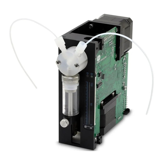
- Page 9 List of Figures Figure 1-1 XLP 6000 Modular Syringe Pump ......1-3 Figure 1-2 Syringe Components .
- Page 10 This page has been intentionally left blank. Cavro® XLP 6000 Modular Syringe Pump Operating Manual, 734237-C, en...
-
Page 11: Getting Started
For more information regarding UL certification of Tecan Systems’ syringe pumps, please visit the Underwriters Laboratories Inc. website at http://www.ul.com/info/standard.htm. Tecan Systems’... -
Page 12: Xlp 6000 Features At-A-Glance
1 - Getting Started XLP 6000 Features at-a-Glance 1.1.2 1.0.1 Radio Interference Radio Interference The XLP 6000 can radiate radio frequency energy, which may cause interference The XLP 6000 can radiate radio frequency energy, which may cause interference to radio and television communications. Follow standard good engineering to radio and television communications. -
Page 13: Functional Description Of The Xlp 6000
1 - Getting Started Functional Description of the XLP 6000 components. To prevent premature failure of pump components, use good ESD practices when handling the XLP 6000. These include, but are not limited to: Using wrist or ankle straps ESD mats or worktables ESD wax on the floor Prepare an ESD-free work area before the chassis is grounded. -
Page 14: Figure 1-2 Syringe Components
1 - Getting Started Functional Description of the XLP 6000 1.4.1 Syringe and Syringe Drive The syringe plunger is moved within the syringe barrel by a lead screw drive that incorporates a 1.8° stepper motor and quadrature encoder to detect lost steps. The syringe drive has a 60 mm travel length and resolution of 6,000 increments (48,000 increments in fine-positioning and microstep mode). -
Page 15: Figure 1-3 3-Port Valve Components
1 - Getting Started Functional Description of the XLP 6000 Figure 1-3 shows the components of a 3-port valve. Figure 1-3 3-Port Valve Components 1.4.3 Printed Circuit Assembly The printed circuit assembly (PCA) holds the microprocessor and circuitry to control the syringe and valve drive. The PCA provides connectors for electrical inputs and outputs as well as a communication address switch. -
Page 16: Figure 1-4 Xlp 6000 Printed Circuit Assembly External Connectors
1 - Getting Started Functional Description of the XLP 6000 Figure 1-4 XLP 6000 Printed Circuit Assembly External Connectors The XLP 6000 PCA has a DA-15 connector to handle power and communications. For more information on the printed circuit assembly inputs/outputs and the address switch, see Chapter 2, "Hardware Setup". -
Page 17: Safety
1 - Getting Started Safety 1.4.5 Multi-Pump Configurations Up to fifteen (15) XLP 6000 pumps can be connected together in a multi-pump configuration (also called “daisy-chaining”). In this configuration each pump is addressed separately from a single terminal via its unique address, which is set using the address switch on the back panel of the pump. -
Page 18: Tips For Setting Up The Xlp 6000
1 - Getting Started Tips for Setting Up the XLP 6000 Pinch Point, Mechanical Hazards Automatically moving parts may cause injuries (crushing, piercing) Attention The general “Read This” symbol indicates the possibility of equipment damage, malfunction or incorrect process results, if instructions are not followed. Tips for Setting Up the XLP 6000 For complete information on setting up the XLP 6000, see Chapter 2, "Hardware Setup"... -
Page 19: Hardware Setup
Power and Electrical Considerations The XLP 6000 requires a 24V DC power supply with a current rating of at least 1.5A, provided through a DA-15 connector. Tecan Systems recommends using one power cable for every two pumps to provide noise immunity, i.e., power should not be daisy-chained to more than two pumps. - Page 20 2 - Hardware Setup Power and Electrical Considerations A current-limiting power supply is recommended. Current limiting above 1.0A is acceptable, assuming that no additional equipment is operated from the supply. If the power supply uses current feedback, the time-current foldback point must be sufficient to allow charging of a 470 µF capacitor without folding back.
-
Page 21: Cabling
2 - Hardware Setup Cabling 2.1.3 Switching Power Supplies Be sure to check carefully the minimum load requirement of the power supply. Typically, switching supplies have a minimum load requirement of up to 10% of the rated output current. Note: The XLP 6000 idle current is less than 10% of the full running current. For example, in a system with multiple XLP 6000 pumps, a 24V 5-amp switcher with a minimum load less that 500mA may not provide sufficient current when the XLP 6000 motors are idle and all other devices are in a low current state. -
Page 22: Communication Interfaces
2 - Hardware Setup Communication Interfaces Function Remarks RS-485 B line Data - Auxiliary output #1 TTL level Auxiliary output #2 TTL level Auxiliary output #3 TTL level Figure 2-1 shows the pin positions of the DA-15 connector on the printed circuit assembly. - Page 23 2 - Hardware Setup Communication Interfaces Examples of cabling connections are shown in Figure 2-2, Figure 2-3, and Figure 2-4 on the following pages. 2.3.1 RS-232/RS-485 Interface The RS-232 interface automatically converts the protocol to RS-485 for the benefit of any other devices which may be connected to the XLP 6000’s RS-485 communication bus (this constitutes the so-called “multi-drop”...
-
Page 24: Figure 2-2 Rs-232 Multi-Pump Cabling
2 - Hardware Setup Communication Interfaces RS-232 Cabling Figure 2-2 RS-232 Multi-Pump Cabling 2 - 6 Cavro® XLP 6000 Modular Syringe Pump Operating Manual, 734237-C, en... -
Page 25: Figure 2-3 Rs-485 Multi-Pump Cabling
2 - Hardware Setup Communication Interfaces RS-485 Cabling Figure 2-3 RS-485 Multi-Pump Cabling Cavro® XLP 6000 Modular Syringe Pump Operating Manual, 734237-C, en 2 - 7... -
Page 26: Figure 2-4 Can Multi-Pump Cabling
2 - Hardware Setup Communication Interfaces CAN Cabling Figure 2-4 CAN Multi-Pump Cabling 2 - 8 Cavro® XLP 6000 Modular Syringe Pump Operating Manual, 734237-C, en... -
Page 27: Settings And Options
2 - Hardware Setup Settings and Options Settings and Options 2.4.1 Configuration Commands The XLP 6000 firmware allows the user to configure the pump for different modes of operation. The U commands (see Chapter 3, "Software Communication") are used to write the configuration information to the non-volatile memory and control the following options: Valve type: The pump can be configured to operate with different valve options (3-port, 4-port, T-valve, Y Block, 3-port distribution, 6-port distribution,... -
Page 28: Figure 2-5 Address Switch
2 - Hardware Setup Settings and Options Figure 2-5 Address Switch To set the address switch: To set the address switch, use a jeweler’s screwdriver or small flat head screwdriver and turn the switch in either direction to the desired position. Note: Power cycle (or power up) the pump after setting the address switch. -
Page 29: Installing Components
2 - Hardware Setup Installing Components 2.4.4 J5 Inputs/Outputs The XLP 6000 provides two auxiliary inputs and three auxiliary outputs that can be accessed through the DA-15 connector, J5. They provide TTL level signals. The outputs are controlled by the [J] command. The auxiliary inputs are located on J5, pins 7 and 8. -
Page 30: Figure 2-6 Xlp 6000 Valve Installation (3-Port Valve Shown)
2 - Hardware Setup Installing Components Figure 2-6 XLP 6000 Valve Installation (3-Port Valve Shown) 2.5.2 Installing a Syringe To install a syringe, follow these steps: Remove the plunger lock screw. Install the syringe as shown in Figure 2-7, following these steps: a. -
Page 31: Mounting
Chapter 5, "Maintenance". Technical Note #001 (PN730317) contains practical tips for the tuse and care of Tecan precision syringes. Mounting The XLP 6000 contains four mounting holes on the front plate of the frame. -
Page 32: Figure 2-8 Xlp 6000 Outline Drawing
2 - Hardware Setup Mounting Figure 2-8 XLP 6000 Outline Drawing 2 - 14 Cavro® XLP 6000 Modular Syringe Pump Operating Manual, 734237-C, en... -
Page 33: Software Communication
3 - Software Communication XLP 6000 Addressing Scheme 3 Software Communication This chapter describes how to communicate with the XLP 6000: through an RS-232, RS-485, or CAN (Controller Area Network) interface. This chapter includes these topics: XLP 6000 Addressing Scheme Communication Protocols Using the XLP 6000 Command Set Initialization... - Page 34 3 - Software Communication XLP 6000 Addressing Scheme Table 3-2 Address Switch Settings in Hex (ASCII) Single Device Dual Device Quad Device All Devices Switch ASCII ASCII ASCII Value to Setting Address Address Address Address Address Address Address Send – <...
-
Page 35: Communication Protocols
For instructions on using a Microsoft Windows Terminal Emulator, see “Using DT Protocol with Microsoft Windows” in this chapter. Note: Tecan Systems recommends using the OEM protocol for RS-232 and RS-485 interfaces. It provides increased error checking through the use of checksums and sequence numbers. - Page 36 3 - Software Communication Communication Protocols ETX (^C or 03h) Checksum Answer Block (see “OEM Protocol Answer Block Characters” for details) STX (^B or 02h) Master address (0 or 30h) Status code Data block (length n) ETX (^C or 03h) Checksum OEM Protocol Command Block Characters The command block characters in the OEM communication protocol are...
- Page 37 3 - Software Communication Communication Protocols The following two scenarios clarify this error detection mechanism. Scenario 1. The computer sends a command block stamped with sequence #1 to the pump. The pump receives the command, sends an acknowledgement to the PC, and executes it.
- Page 38 3 - Software Communication Communication Protocols 0 for non-repeated / 1 for repeated SQ0 – SQ2 Sequence value, as follows: Sequence Value Note: Bits 4 through 7 are always fixed to the values shown. Data Block (length n) The data block consists of the data or commands sent to the pump or host (this is an ASCII string).
- Page 39 3 - Software Communication Communication Protocols Master Address The master address is the address of the host system. This should always be 30h (ASCII value “0”). Status and Error Codes The status and error codes define pump status and signal error conditions. For a description of status and error codes, see “Error Codes and Pump Status”...
- Page 40 3 - Software Communication Communication Protocols Data block (if applicable) ETX (03h) Carriage return (0Dh) Line feed (0Ah) DT Protocol Command Block Characters The command block characters in the DT communication protocol are described below. Start Block The start character indicates the beginning of a message block. Pump Address The pump address is an ASCII character specific to each pump.
- Page 41 3 - Software Communication Communication Protocols Carriage Return (0Dh)/Line Feed (0Ah) This character terminates the reply block. 3.2.3 Using DT Protocol with Microsoft Windows The XLP 6000 can be controlled in DT protocol mode directly from the Microsoft Windows terminal accessory. To communicate with the XLP 6000 using Windows 3.x, follow these steps: Connect the XLP 6000 to a communications port of the PC (for example, COM1).
- Page 42 Note: All Tecan XLP 6000 systems use CAN controller chips compatible with Phillips Semiconductor CAN bus specification, version 2.0. When using the CAN interface, termination resistors (120 ohm) are necessary at both ends of the bus.
-
Page 43: Figure 3-1 Can Message Structure
3 - Software Communication Communication Protocols Represent the length of the data block. Data blocks can be from zero to eight bytes in length. Any message that requires more than eight bytes must be sent in a series of multi-frame messages. The receiving unit then assembles the separate frames into one long string. - Page 44 This lets the device know what type of message is coming. See “CAN Frame Types” in this chapter. This bit is not used in Tecan Systems’ CAN implementation and should always be set to 0. This will always be set to 0 for standard format frames.
- Page 45 3 - Software Communication Communication Protocols Common Commands, Type 2 This frame type is used for commands that are common to every device on the bus. The frame type is set to 2 and the command is a single ASCII character in the data block.
- Page 46 3 - Software Communication Communication Protocols Report current valve position Report buffer status Report status of input #1 Report status of input #2 Report the number of pump initializations Report the number of plunger movements Report the number of valve movements Report the number of valve movements since last report Report checksum Report firmware version...
- Page 47 3 - Software Communication Communication Protocols Example 1. The pump is set to address 0 Pump sends: Group Device Frame Length 0000 0000 Host acknowledges: Group Device Frame Length Node ID Slave ID 0000 0010 0010 0000 0010 0000 Host acknowledges the boot request with: Dir = 0 Host to slave Note:...
- Page 48 3 - Software Communication Communication Protocols Example 2. The pump is set to address 6 Pump sends: Group Device Frame Length 0110 0000 Host acknowledges: Group Device Frame Length Node ID Slave ID 0000 0010 0010 0110 0010 0110 Host acknowledges the boot request with: Dir = 0 Host to slave Note:...
-
Page 49: Action Command
3 - Software Communication Communication Protocols <DLC> 4-bit data length code <Answer> Data bytes block. The first byte of the data block is always the status byte, which is an error code (same error codes used with the RS232 and RS485 protocols) added to Ox20h. - Page 50 3 - Software Communication Communication Protocols Multi-Frame Command The host commands [Z2S5gIA3000OgHD300G10G5R] to a pump, and the pump is set to address 0. Host sends: XXXXXXX 1000 Z2S5gA3 Slave ID Frame type Data bytes XXXXXXX 1000 000OgHD30 Slave ID Frame type Data bytes XXXXXXX 1000...
-
Page 51: Report Command
3 - Software Communication Communication Protocols Host sends: XXXXXXX 0010 Slave ID Frame Type Data bytes Pump reports: XXXXXXX 0010 <20h><60h> Slave ID Frame Type Note: For query commands, no acknowledge frame is needed. Report Command The host sends command report 23 of frame type 6 to a pump, and the pump is set to address 1. -
Page 52: Using The Xlp 6000 Command Set
3 - Software Communication Using the XLP 6000 Command Set Using the XLP 6000 Command Set The XLP 6000 features a robust command set which allows a wide range of parameters to be defined by the user. Many of the commands have default values;... - Page 53 3 - Software Communication Using the XLP 6000 Command Set Command Syntax and Notes The syntax for each command in the command set is: <n> Numerical value within a given range 0..6000 Range of numerical values allowed Default value Note: •...
- Page 54 3 - Software Communication Using the XLP 6000 Command Set K<n> Backlash Increments The [K] command sets the number of backlash increments. The syntax for this command is: [K<n>] where <n> = 0..31 in full step mode (12 is the default), and <n>...
-
Page 55: Initialization
3 - Software Communication Initialization Table 3-5 Write Pump Configuration Command Values Value<n> Description Set RS-232/RS-485 Baud rate to 38400 Set CAN Bus Baud rate to 100K Set CAN Bus Baud rate to 250K Set CAN Bus Baud rate to 500K Set CAN Bus Baud rate to 1M Set CAN Bus Baud rate to 125K Note: [U] commands take effect upon the pump's next power-up. - Page 56 3 - Software Communication Initialization k <n> Syringe Dead Volume Command The [k] command sets the number of increments that the plunger drive is offset from the top of travel. This is to minimize dead volume. The syntax for this command is: [k<n>] where: <n>...
- Page 57 3 - Software Communication Initialization Z Parameter Value Description <n > Initializes at full plunger force and at default initialization speed (default) Initializes at half plunger force and at default initializa- tion speed Initializes at one-third plunger force and at default initialization speed 10-40 Initializes at full force and at speed code <n...
- Page 58 3 - Software Communication Initialization <n > Sets initialization input port to port 1 (default) 1..X Sets initialization input port for distribution valves, where X is the number of ports on the valve. <n > Sets initialization output port to port X (default), where X is the number of ports on the valve.
-
Page 59: Operating Commands
3 - Software Communication Operating Commands w<n > Initialize Valve Drive The [w] command initializes the valve drive only. Because the plunger is not initialized, only the initialization port can be set. = Set port = Set valve homing and port numbering direction The parameters are described below. -
Page 60: Figure 3-2 Valve Position Examples For 3-Port Non-Distribution Valves
3 - Software Communication Operating Commands the direction in which the valve homes during initialization (clockwise or counterclockwise) the direction in which the ports are numbered, starting with the syringe port (clockwise or counterclockwise) After initialization, the direction in which the valve moves is specific to the valve type and command. -
Page 61: Figure 3-3 Valve Position Examples For 3-Port Distribution Valves
3 - Software Communication Operating Commands Because the syringe port is always a common port, in distribution valves, the [B] (Bypass) and [E] (Extra) commands are meaningless. However, the commands are available, to provide backward compatibility with earlier versions of firmware. For example, in Figure 3-3, if the 3-port distribution valve has been initialized with the [Y] command, the ports will be numbered as shown in the bottom diagram (counterclockwise). -
Page 62: Figure 3-4 Valve Position Examples For 4-Port Non-Distribution Valves
3 - Software Communication Operating Commands O<n> Move Valve Counterclockwise to Port n (Distribution Valves) The [O<n>] command sets the valve position to port [n], moving in a counter- clockwise direction. This command is independent of input or output characteristics. Move Valve to Bypass (Non-distribution Valves) The [B] command connects the input and output positions, bypassing the syringe. -
Page 63: Figure 3-5 Valve Position Examples For T Valves (Non-Distribution)
3 - Software Communication Operating Commands Figure 3-5 Valve Position Examples for T Valves (Non-Distribution) Figure 3-6 Valve Position Examples for 6-Port Distribution Valves Cavro® XLP 6000 Modular Syringe Pump Operating Manual, 734237-C, en 3 - 31... -
Page 64: Figure 3-7 Valve Position Examples For 9-Port Distribution Valves
3 - Software Communication Operating Commands Figure 3-7 Valve Position Examples for 9-Port Distribution Valves 3.5.2 Plunger Movement Commands A <n> Absolute Position The [A] command moves the plunger to the absolute position <n>, where <n> = 0..6000 in standard mode and 0..48000 in fine positioning and microstep mode. - Page 65 3 - Software Communication Operating Commands a <n> Absolute Position (Not Busy) This is the same as the [A] command, except that the status bit within the reply string indicates that the pump is not busy. P <n> Relative Pickup The [P] command moves the plunger down the number of increments commanded.
- Page 66 3 - Software Communication Operating Commands <n> Parameter Command Value Description 0-6000 Relative position in half increments (N=0) 0-48000 Relative position in microsteps (N=1) 0-48000 Relative position in microsteps (N=2) For example: The syringe plunger is at position 3000. [D300] will move the plunger up 300 increments to an absolute position of 2700.
- Page 67 3 - Software Communication Operating Commands Note: Unless the top speed is less than or equal to the start or cutoff speed, always program the pump in order of the move: start speed [v], top speed [V], cutoff speed [c]. Changing Speed on the Fly Speed changes can be made while the syringe plunger is moving.
- Page 68 3 - Software Communication Operating Commands 20000 22500 25000 27500 30000 32500 35000 37500 40000 42500 45000 47500 50000 v <n> Set Start Speed The [v] command sets the speed at which the plunger begins its movement, in pulses/sec. The plunger will then ramp up (slope) to the top speed. The start speed should always be less than the top speed.
- Page 69 These speed settings do not cover the full range of speeds the plunger can travel. They are commonly used speeds provided for the convenience of the user. All times are approximate and will vary with different ramp speeds and cutoffs. Tecan Systems also provides a utility for performing theoretical speed calculations in Pump:Link Evaluation Software (in the Utility menu on the user interface).
- Page 70 3 - Software Communication Operating Commands 1600 3.77 30.0 1400 4.30 34.3 1200 5.00 40.0 1000 6.00 48.0 7.50 60.0 10.00 80.0 15.00 30.00 31.58 33.33 35.29 37.50 40.00 42.86 46.15 50.00 54.55 60.00 66.67 75.00 85.71 100.00 120.00 150.00 1200 200.00 1600...
- Page 71 3 - Software Communication Operating Commands 375.00 3000 428.57 3429 500.00 4000 600.00 4800 Note: To achieve maximum stroke time of 20 minutes for N=0, N=1 or 160 minutes for N=2, a set speed [S] cannot be used. The pump must be programmed using the [V5] command.
- Page 72 3 - Software Communication Operating Commands Speed. And if the Cutoff Speed is set less than Start Speed, it will be ignored and the Cutoff Speed will be set equal to the Start Speed. 3.5.5 Control Commands Execute Command or Program String The [R] command tells the pump to execute a new or previously loaded but unexecuted command string.
- Page 73 3 - Software Communication Operating Commands Table 3-7 Example Program String Command Segment Description Move plunger to position 0. Outer loop start. Move plunger down 50 increments. Inner loop start. P100 Move plunger down 100 increments. D100 Move plunger up 100 increments. Inner loop, repeat 10 times.
- Page 74 3 - Software Communication Operating Commands Note: If the value of <n> is not specified, <n> defaults to 0. The status of the TTL input lines can also be read using [?13 ]and [?14]. These commands are described in “Report Commands” later in this chapter. Terminate Command The [T] command terminates plunger moves in progress ([A], [a], [P], [p], [D], and [d]), control loops, and delays [M].
- Page 75 3 - Software Communication Operating Commands 0 = low; for example, Gnd 1 = high; for example, +5V DC 3.5.6 Non-Volatile Memory (EEPROM) Commands The non-volatile memory in the XLP 6000 can store a program string thus providing the user with the option of computer-free operation. The pump can be configured to run stored programs using the U<30>...
- Page 76 3 - Software Communication Operating Commands e <n> Execute Non-Volatile Memory Program String Non-volatile memory command strings are executed by sending an [e] command. The executing program string can be terminated using the [T] command. [e<n>] where <n> = 0..14 (the string number) Note: An Initialization command should always be included in the non-volatile memory command string if the pump will be used in standalone mode.
-
Page 77: Report Backlash Increments)
3 - Software Communication Operating Commands 3.5.7 Report Commands Report commands do not require an [R] command. All Report commands are invalid in CAN communication. The frame type 6 is provided to retrieve information from the pump. For more information, see Appendix F, "CAN Communication Commands". -
Page 78: Report Auxiliary Input #2 Status)
3 - Software Communication Operating Commands Report Status of Auxiliary Input #1 (J5, Pin 7) 0 = low 1 = high Report Status of Auxiliary Input #2 (J5, Pin 8) 0 = low 1 = high Report Number of Pump Initializations Command [?15] reports the number of pump initializations. -
Page 79: Error Codes And Pump Status
3 - Software Communication Error Codes and Pump Status ?29 or Q Report the Device Status The [?29] command reports device status (error code). Report Pump Configuration The [?76] command reports pump configuration in ASCII text. Report Voltage The [*] command reports the value of the device power supply. The value is multiplied by 10. - Page 80 Device Not Initialized. This error occurs when the pump is not initial- ized. To clear the error, initialize the pump. 8 (08h) Internal failure. If this error occurs, please call Tecan Systems Tech- nical Services. See Chapter 6, “Technical Service.” 9 (09h) Plunger Overload.
- Page 81 Internal failure. If this error occurs, please call Tecan Systems Tech- nical Services. See Chapter 6, “Technical Service.” 14 (0Eh) A/D converter failure. This error occurs when the internal A/D converter is faulty. If this error occurs, please call Tecan Systems Technical Services. See Chapter 6, “Technical Service.” 15 (0Fh) Command Overflow.
- Page 82 3 - Software Communication Error Codes and Pump Status If the [Q] command indicates the pump has not initialized, the pump must be reinitialized until the [Q] command indicates successful initialization. If initialization is not successful, a “Device Not Initialized” error is returned as soon as the next Move command is sent.
- Page 83 3 - Software Communication Error Codes and Pump Status Status Byte Hex # if Bit 5 = Dec # if Bit 5 = Error Code 0 1 X 0 0 1 1 1 Device not Initialized 0 1 X 0 1 0 0 0 Internal failure 0 1 X 0 1 0 0 1 Plunger Overload...
- Page 84 3 - Software Communication Error Codes and Pump Status This page has been intentionally left blank. 3 - 52 Cavro® XLP 6000 Modular Syringe Pump Operating Manual, 734237-C, en...
-
Page 85: Glossary
4 - Setting Up the XLP 6000 for Your Application Glossary 4 Setting Up the XLP 6000 for Your Application The XLP 6000 is capable of providing precision pumping in a wide variety of liquid handling systems. The interplay of fluid viscosity, aspiration and dispense speeds, and system geometry (syringe size, tubing inner diameter, and valve inner diameter) determine the behavior of the XLP 6000 in a particular application. - Page 86 4 - Setting Up the XLP 6000 for Your Application Glossary carryover Contamination of a volume of fluid by residual fluid from a previous aspiration or dispense. Carryover causes variability in final volume and concentration. cavitation Formation of air bubbles due to rapid pressure changes. Often caused by aspirating fluid into the syringe too quickly.
-
Page 87: Figure 4-1 Syringe Speed
4 - Setting Up the XLP 6000 for Your Application Glossary Figure 4-1 Syringe Speed Speed [Hz] time in s start speed (v) The speed at which the syringe plunger starts moving. top speed (V) The maximum speed at which the syringe plunger moves. cutoff speed (c) The speed of the syringe plunger just before stopping. -
Page 88: Optimizing Xlp 6000 Performance
4 - Setting Up the XLP 6000 for Your Application Optimizing XLP 6000 Performance Optimizing XLP 6000 Performance Caution! Run the pump only in the upright position. Do not move the pump valve or syringe plunger without first wetting or priming the pump. For command details, see Chapter 3, "Software Communication". - Page 89 4 - Setting Up the XLP 6000 for Your Application Optimizing XLP 6000 Performance Minimum Flow Rate Maximum Flow Rate Syringe Size (mL/min) (mL/min) 1 mL 6.25 x 10 50.0 5 mL 3.125 x 10 250.0 10 mL 6.25 x 10 500.0 25 mL 0.15625...
- Page 90 4 - Setting Up the XLP 6000 for Your Application Optimizing XLP 6000 Performance Possible errors: – No response. Check for loose or incorrectly connected cables, or connection to the wrong computer COM port. Retry. Initialize pump and set initialization speed. The following information assumes that your input tubing connects to the right valve port.
- Page 91 4 - Setting Up the XLP 6000 for Your Application Optimizing XLP 6000 Performance should be slow (to avoid cavitation) and dispense fast (to promote breakoff). Since cavitation and breakoff will affect both accuracy and precision, speed settings may be optimized separately for aspiration and dispense. Using aspirate/dispense commands, set start speed [v] and top speed [V] to meet application throughput goals.
-
Page 92: Helpful Hints
4 - Setting Up the XLP 6000 for Your Application Helpful Hints Helpful Hints To maintain pump performance, keep the following in mind when operating the XLP 6000: Wipe up all spills immediately. Pumping cold fluids may cause leaks, the result of differing coefficients of expansion of Teflon and glass. -
Page 93: Daily Maintenance
5 - Maintenance Daily Maintenance 5 Maintenance Although required maintenance may vary with your application, the following procedures are recommended for optimal performance of the Cavro® XLP 6000 Modular Syringe Pump. Perform maintenance tasks in these intervals: daily weekly periodically Daily Maintenance To ensure proper operation of the XLP 6000, perform these tasks daily: Inspect the pump(s) for leaks, and correct any problems. -
Page 94: Periodic Maintenance
100 can be purchased through Fisher Scientific. Order catalog number 04-355-27 for a 1 gallon container. Note: RoboScrub is a phosphate-free detergent for cleaning and conditioning liquid handling systems. RoboScrub is available from Tecan (PN 70-736) in a 16 oz. container. 5.2.2... - Page 95 Quality Control Assurance Check the accuracy and precision of the XLP 6000 on a regular basis. Tecan Systems recommends checking both accuracy and precision gravimetrically, using an analytical balance with the capability to measure to 0.1 mg. Gravimetric measurements should be corrected for the specific gravity of water at the ambient temperature.
- Page 96 5 - Maintenance Periodic Maintenance % Coefficient of Variation = (Standard Deviation/Mean) * 100 ⎛ ⎞ ⎧ ⎫ ⎜ ⎟ ∑ − ⎨ ⎬ ⎜ ⎟ − ⎩ ⎭ ⎜ ⎟ %CV = ⎜ ⎟ ⎜ ⎟ ⎝ ⎠ ⎡ ⎤...
-
Page 97: Figure 5-1 Syringe Replacement
5 - Maintenance Periodic Maintenance Unscrew the syringe from the valve. To install the syringe: (as shown in Figure 5-1) a. Screw the syringe into the valve. b. Pull the syringe plunger down to the plunger holder assembly. c. Screw the syringe plunger into place. d. -
Page 98: Figure 5-2 Syringe Seal Assembly
5 - Maintenance Periodic Maintenance Remove the syringe plunger from the barrel. Using a single edged razor or precision knife, carefully slice the old seal lengthwise and remove them from the plunger. Replace the “O”-ring and wet the new “O” ring and plunger tip with distilled or deionized water. -
Page 99: On-Site Replacements
5 - Maintenance On-Site Replacements Replace the valve screws but do not tighten completely. Move the plunger carriage to the bottom of travel and install the syringe. Pull the syringe plunger until it is above the carriage and align the valve using the plunger as a guide. Tighten from 1/4 to 1/2 turn after the screws contact the valve body. - Page 100 5 - Maintenance On-Site Replacements This page has been intentionally left blank. 5 - 8 Cavro® XLP 6000 Modular Syringe Pump Operating Manual, 734237-C, en...
-
Page 101: Technical Service
6 - Technical Service 6 Technical Service For information or questions regarding ordering or operating the Cavro® XLP 6000 Modular Syringe Pump, please contact Tecan Systems Technical Service using one of the methods listed below. By phone 408-953-3100 or 800-231-0711... -
Page 102: Figure 6-1 Xlp 6000 Label Location
6 - Technical Service Figure 6-1 XLP 6000 Label Location 6 - 2 Cavro® XLP 6000 Modular Syringe Pump Operating Manual, 734237-C, en... -
Page 103: Available Configurations
A - Ordering Information Available Configurations A Ordering Information This appendix is a summary of available XLP 6000 configurations, other Tecan Systems liquid handling components, and spare parts for the XLP 6000. Available Configurations All configurations support RS-232, RS-485, and CAN communications. -
Page 104: Xlp 6000 Spare Parts
A - Ordering Information XLP 6000 Spare Parts XLP 6000 Spare Parts The following spare parts are available: Syringes Interconnect Tubing Seals Pump Evaluation Accessories Valves Miscellaneous Parts Printed Circuit Boards A.2.1 Syringes Table A-2 Syringes Part Number Description 734801 Syringe, 50 µL 734802 Syringe, 100 µL... - Page 105 Ceramic Valve, 9-Port Distribution (1/4-28" fitting) * Part numbers followed by an asterisk have been reserved pending release. Please check with your local Tecan Systems representative for availability. Cavro® XLP 6000 Modular Syringe Pump Operating Manual, 734237-C, en A - 3...
- Page 106 A - Ordering Information XLP 6000 Spare Parts A.2.4 Printed Circuit Board Assemblies Table A-5 Printed Circuit Board Assembly and RS485 Converter Board Assembly Part Number Description 737300 PCA, XLP 6000 232/485/CAN A.2.5 Interconnect Tubing Table A-6 Tubing Part Length Number Description Material...
- Page 107 A - Ordering Information XLP 6000 Spare Parts Part Length Number Description Material (Inches) Units Tube Ends 725788 Interconnect tube 8" .051 1/4-28" to 1/4-28" 725876 Aspirate/Dispense tube 30" .059 1/4-28" to M6 725896 Interconnect tube 20" .060 1/4-28" to 1/4-28" 726172 Aspirate/Dispense tube 24"...
-
Page 108: Other Tecan Systems Products
A.3.2 MSP 9250/9500 Mini Sample Processors One- or two-arm robotic benchtop workstations designed for automating sample preparation or assay methods. Tecan Systems’ modular component technology allows both flexibility and quick customization. A variety of liquid-handling modules and a choice of standard cap-piercing, disposable tip, or multi-channel probes are available. - Page 109 RS-232 or RS-485. It can also be placed on an RS-485 bus with other Tecan Systems pumps and smart devices. The I/O signal is CMOS (0-5 volts). I/O lines include 16 inputs, 16 outputs, and four analog inputs. The board uses a standard Cavro OEM communications protocol.
-
Page 110: Mating Connector Suppliers
Active Wash Station. A.3.10 Accessories and Consumables Tecan Systems provides a full range of accessories and consumables to keep your instrumentation in tip-top shape. These include consumables such as probes and syringes, seal kits, tubing and valves or accessories such as I/O boards, linear drive boards, or enhancement kits for your system. -
Page 111: B Plunger Information
B Plunger Information Typical Plunger Force Tecan Systems specifies that all new XLP 6000 Pumps running at a speed of 5600 pulses/sec will lift a 15-pound weight attached to the plunger drive pin. Tecan Systems cannot warrant the pump for use beyond these specifications. -
Page 112: Plunger Time Calculations
B - Plunger Information Plunger Time Calculations Symbol Name Range (n) Unit Total Move Time Seconds Ramp Up increments Half increments Ramp Up increments Half increments Ramp Up increments Half increments Note: • Cutoff speed cannot be less than start speed. •... - Page 113 B - Plunger Information Plunger Time Calculations Case 2. Ramp Up, Constant Speed, Ramp Down < Case 2 is used when Diagram of Move: Speed [Hz] time in s Calculation: v = 50 Hz L = 14 V = 5800 Hz A = 3000 full increments c = 500 Hz Ramp Up increments...
- Page 114 B - Plunger Information Plunger Time Calculations Constant Speed increments − − = ∗ − − half increments 2 3000 481 477 5042 Constant Speed Time seconds Total Move Time seconds 16 87 15 1 18 Case 3. Move Too Small to Reach Cutoff Speed Case 3 is used when Vn <...
- Page 115 B - Plunger Information Plunger Time Calculations Total Move Time − − Vn v 838 50 seconds ∗ 14 2500 Ramp Up increments full increments Case 4. Move Too Small to Reach Top Speed Case 4 is used when Vn < V and Vn > c Diagram of Move: Speed [Hz] time in s...
- Page 116 B - Plunger Information Plunger Time Calculations This page has been intentionally left blank. B - 6 Cavro® XLP 6000 Modular Syringe Pump Operating Manual, 734237-C, en...
-
Page 117: Cascii Chart Of Codes For U.s. Characters
C - ASCII Chart of Codes for U.S. Characters C ASCII Chart of Codes for U.S. Characters Table C-1 ASCII Chart of Codes for U.S. Characters Character or Character or Decimal Hexadecimal Function Decimal Hexadecimal Function none Cavro® XLP 6000 Modular Syringe Pump Operating Manual, 734237-C, en C - 1... - Page 118 C - ASCII Chart of Codes for U.S. Characters Character or Character or Decimal Hexadecimal Function Decimal Hexadecimal Function \ (backslash) ^ (control) — (emdash) ` (tick) " & ' (apostrophe) , (comma) - (en dash) . (period) C - 2 Cavro®...
- Page 119 C - ASCII Chart of Codes for U.S. Characters Character or Character or Decimal Hexadecimal Function Decimal Hexadecimal Function (left brace) (vertical bar) < (right brace) ~ (tilde) > Cavro® XLP 6000 Modular Syringe Pump Operating Manual, 734237-C, en C - 3...
- Page 120 C - ASCII Chart of Codes for U.S. Characters This page has been intentionally left blank. C - 4 Cavro® XLP 6000 Modular Syringe Pump Operating Manual, 734237-C, en...
-
Page 121: D Chemical Resistance Chart
The information provided in the table that starts on the next page has been supplied to Tecan Systems by other reputable sources and is to be used ONLY as a guideline. Before permanent installation, test the equipment with the chemicals under the specific conditions of your application. - Page 122 D - Chemical Resistance Chart Chemical Kel-F Teflon Polypropylene Acetaldehyde A- Excellent A- Excellent C1-Fair Acetamide A- Excellent A- Excellent A2-Excellent Acetate Solvent A1- Excellent A- Excellent C1-Fair Acetic Acid A- Excellent A- Excellent A2-Excellent Acetic Acid 20% A- Excellent A- Excellent A2-Excellent Acetic Acid 80%...
- Page 123 D - Chemical Resistance Chart Chemical Kel-F Teflon Polypropylene Aluminum Potassium Sulfate 100% A- Excellent A- Excellent A-Excellent Aluminum Sulfate A- Excellent A- Excellent A-Excellent Amines (General) A- Excellent A2- Excellent B2-Good Ammonia, anhydrous A- Excellent A- Excellent A-Excellent Ammonia, Aqueous A- Excellent A- Excellent A-Excellent...
- Page 124 D - Chemical Resistance Chart Chemical Kel-F Teflon Polypropylene Arsenic Acid A- Excellent A-Excellent Arsenic Salts B1-Good Asphalt A- Excellent A1- Excellent A2-Excellent Barium Carbonate A- Excellent A- Excellent A-Excellent Barium Chloride A- Excellent A- Excellent A-Excellent Barium Cyanide A1- Excellent D-Severe Effect Barium Hydroxide A- Excellent...
- Page 125 D - Chemical Resistance Chart Chemical Kel-F Teflon Polypropylene Butyric Acid A- Excellent A- Excellent A2-Excellent Calcium Bisulfate A1-Excellent Calcium Bisulfide A- Excellent A- Excellent A-Excellent Calcium Bisulfite A- Excellent A- Excellent A-Excellent Calcium Carbonate A- Excellent A-Excellent Calcium Chloride A- Excellent A- Excellent A-Excellent...
- Page 126 D - Chemical Resistance Chart Chemical Kel-F Teflon Polypropylene Citric Acid A2- Excellent A- Excellent A-Excellent Citric Oils A1-Excellent Clorox® (Bleach) A- Excellent A- Excellent A2-Excellent Copper Chloride A- Excellent A- Excellent A-Excellent Copper Cyanide A- Excellent A-Excellent Copper Nitrate A- Excellent A- Excellent A-Excellent...
- Page 127 D - Chemical Resistance Chart Chemical Kel-F Teflon Polypropylene Ethanolamine D- Severe Effect A1- Excellent A1-Excellent Ether B1- Good A- Excellent D-Severe Effect Ethyl Acetate A1- Excellent A- Excellent A-Excellent Ethyl Benzoate A1- Excellent A- Excellent D-Severe Effect Ethyl Ether A1- Excellent A- Excellent D-Severe Effect...
- Page 128 D - Chemical Resistance Chart Chemical Kel-F Teflon Polypropylene Fuel Oils A- Excellent A- Excellent B1-Good Furan Resin A1- Excellent A- Excellent D-Severe Effect Furfural D- Severe Effect A- Excellent D-Severe Effect Gallic Acid A1- Excellent A- Excellent A-Excellent Gasoline (high-aromatic) A1- Excellent A- Excellent A1-Excellent...
- Page 129 D - Chemical Resistance Chart Chemical Kel-F Teflon Polypropylene Isooctane A1- Excellent A- Excellent A1-Excellent Isopropyl Acetate A- Excellent B1-Good Isopropyl Ether A1- Excellent A- Excellent D-Severe Effect Kerosene A- Excellent A- Excellent B1-Good Ketones A1- Excellent A- Excellent B1-Good Lacquer Thinners A2- Excellent A- Excellent...
- Page 130 D - Chemical Resistance Chart Chemical Kel-F Teflon Polypropylene Methyl Acetate A1- Excellent A- Excellent B1-Good Methyl Acetone A- Excellent Methyl Acrylate A1- Excellent A- Excellent C1-Fair Methyl Bromide A1- Excellent A- Excellent D-Severe Effect Methyl Butyl Ketone A- Excellent D-Severe Effect Methyl Cellosolve A- Excellent...
- Page 131 D - Chemical Resistance Chart Chemical Kel-F Teflon Polypropylene Oil Crude, Sour A- Excellent A- Excellent B1-Good Oil Crude, Sweet A- Excellent A- Excellent C1-Fair Oil Mineral A- Excellent A- Excellent A1-Excellent Oleic Acid A1- Excellent A- Excellent B2-Good Oleum 100% A1- Excellent A- Excellent D-Severe Effect...
- Page 132 D - Chemical Resistance Chart Chemical Kel-F Teflon Polypropylene Potassium Cyanide Solutions A1- Excellent A- Excellent A-Excellent Potassium Ferricyanide A1- Excellent A- Excellent A-Excellent Potassium Ferrocyanide A1- Excellent A- Excellent A-Excellent Potassium Hydroxide (Caustic Pot- A1- Excellent A- Excellent A-Excellent ash) Potassium Hypochlorite A1- Excellent...
- Page 133 D - Chemical Resistance Chart Chemical Kel-F Teflon Polypropylene Sodium Bromide A1- Excellent A- Excellent A-Excellent Sodium Carbonate A- Excellent A- Excellent A-Excellent Sodium Chlorate A1- Excellent A- Excellent A-Excellent Sodium Chloride A1- Excellent A- Excellent A-Excellent Sodium Chromate A1- Excellent A- Excellent A-Excellent Sodium Cyanide...
- Page 134 D - Chemical Resistance Chart Chemical Kel-F Teflon Polypropylene Starch A1- Excellent A- Excellent A-Excellent Stearic Acid A- Excellent A1-Excellent Styrene A- Excellent D-Severe Effect Sulfur Chloride A1- Excellent A- Excellent D-Severe Effect Sulfur Dioxide A- Excellent C1-Fair Sulfur Trioxide A1- Excellent A- Excellent D-Severe Effect...
- Page 135 D - Chemical Resistance Chart Chemical Kel-F Teflon Polypropylene Water, Deionized A1- Excellent A2- Excellent A-Excellent Water, Distilled A- Excellent A- Excellent A-Excellent Water, Fresh A- Excellent A- Excellent A-Excellent Water, Salt A- Excellent A- Excellent A-Excellent Xylene A- Excellent A- Excellent C1-Fair Zinc Chloride...
- Page 136 D - Chemical Resistance Chart This page has been intentionally left blank. D - 16 Cavro® XLP 6000 Modular Syringe Pump Operating Manual, 734237-C, en...
-
Page 137: Exlp 6000 Physical Specifications
E - XLP 6000 Physical Specifications E XLP 6000 Physical Specifications Table E-1 XLP 6000 Physical Specifications Note: Specifications listed here are subject to change without notice. Dimensions Height 10.00 in. (254 mm) Width 2.56 in. (65 mm) Depth 4.76 in. (121 mm) from front panel to connector Weight 4.70 lb. - Page 138 E - XLP 6000 Physical Specifications Valves Plug Material Virgin Teflon Body Material Kel-F Fittings 1/4-28 and M6 tubing fittings 1/4-28" syringe fitting Valve Options 120° 3-port 90° 4-port 3-port distribution Y block T valve 6-port distribution 9-port distribution Fluid Contact Glass, Kel-F, Teflon, ceramic Power Requirements Voltage...
- Page 139 Safety and Regulatory Compliance The XLP 6000 uses only UL recognized electronic components and bears the UL Recognized component mark: Tecan Systems’ UL customer file number is E164638. Cavro® XLP 6000 Modular Syringe Pump Operating Manual, 734237-C, en E - 3...
- Page 140 E - XLP 6000 Physical Specifications This page has been intentionally left blank. E - 4 Cavro® XLP 6000 Modular Syringe Pump Operating Manual, 734237-C, en...
-
Page 141: Fcan Communication Commands
F - CAN Communication Commands F CAN Communication Commands Command Type Command Valid/Invalid CAN Equivalent Initialization Z, Y, W Valid None Initialization Valid None Plunger Movement A, a, P, p, D, d Valid None Valve I, O, B Valid None Valve E, ^ Valid... - Page 142 F - CAN Communication Commands Command Type Command Valid/Invalid CAN Equivalent Report Invalid Frame type = 6 Command = “20” (ASCII) Report Invalid Frame type = 6 Command = “18” (ASCII) Report Invalid Frame type = 6 Command = “19” (ASCII) Report Invalid None...
-
Page 143: G Command Quick Reference
G - Command Quick Reference Pump Configuration Commands G Command Quick Reference Pump Configuration Commands Command Values of <n> Description 0 = fine positioning mode off Enables or disables microstepping 1 = fine positioning mode on or fine positioning mode 2 = microstep mode on 0 = No Valve Writes configuration information to... -
Page 144: Initialization Commands
G - Command Quick Reference Initialization Commands Initialization Commands Command Values of <n> Description <n > Initializes the plunger drive 0 = initializes at full plunger force and homes the valve in a 1 = initializes at half plunger force clockwise direction. - Page 145 G - Command Quick Reference Initialization Commands Command Values of <n> Description <n > Initializes the valve drive only. 1..X = Set initialization port where X is the number of ports on the valve <n > Initializes the valve drive only. 0 = Valve homes in a clockwise direction;...
-
Page 146: Valve Commands
G - Command Quick Reference Valve Commands Valve Commands Command Description Moves valve to input position Moves valve to output position Moves valve to bypass position Moves valve to extra position Plunger Movement Commands/Status Bit Reports Command Value of <n> Description Status A <n>... -
Page 147: Set Commands
G - Command Quick Reference Set Commands Set Commands Command Value of <n> Description Default Setting L <n> 1..20 Slope (14) v <n> 50..1000 Start speed (Hz/sec) (900) V <n> 5..6000 Peak speed (Hz/sec) (1400) S <n> 0..40 Set speed (11) c <n>... -
Page 148: Non-Volatile Memory (Eeprom) Commands
G - Command Quick Reference Non-Volatile Memory (EEPROM) Commands Non-Volatile Memory (EEPROM) Commands Command Value of <n> Description s <n> 0..14 Loads command string in Non-Volatile Memory e <n> 0..14 Executes Non-Volatile Memory command string Clears “Run from Non-Volatile Memory” flag. Sets “Run from Non-Volatile Memory”... -
Page 149: Error Codes
G - Command Quick Reference Error Codes Same as Q (query, status and error bytes) Report pump configuration Report supply voltage < <n> Report user data (0..15) Error Codes Command Description Notes Error free condition 1 (01h) Initialization error Fatal error. Reinitialize pump before resuming normal operation. -
Page 150: Error Codes And Status Byte
G - Command Quick Reference Error Codes and Status Byte G.10 Error Codes and Status Byte Status Byte Hex # if Bit 5 = Dec # if Bit 5 = Error Code 7 6 5 4 3 2 1 0 or 1 or 1 Number... -
Page 151: Da-15 Connector Pin Assignments
G - Command Quick Reference DA-15 Connector Pin Assignments Function Remarks Ground Power and logic RS-485 A line Data + RS-485 B line Data - Auxiliary output #1 TTL level Auxiliary output #2 TTL level Auxiliary output #3 TTL level Cavro®... - Page 152 G - Command Quick Reference DA-15 Connector Pin Assignments This page has been intentionally left blank. G - 10 Cavro® XLP 6000 Modular Syringe Pump Operating Manual, 734237-C, en...
- Page 153 ..... . carryover ..... . .
- Page 154 ... ?25 (Report slope code setting) 3-46 communication interfaces ....?28 (Report current mode) 3-46 communication protocols .
- Page 155 ....firmware specifications ......flowrate ranges OEM communication protocol .
- Page 156 . . . RSP 9000 Robotic Sample Processor Tecan Systems ......safety ....
- Page 157 ... . valve drive specifications valve positions ..3-port distribution valve 3-29 ....3-port valve 3-28 .
Need help?
Do you have a question about the cavro xlp 6000 and is the answer not in the manual?
Questions and answers