Table of Contents
Advertisement
Quick Links
Download this manual
See also:
Service Manual
Advertisement
Table of Contents
Troubleshooting

Related Manuals for Fluke 2680A


Summary of Contents for Fluke 2680A
- Page 1 ® 2680A/2686A Data Acquisition System/Data Logging System Users Manual June 2002, Rev. 1, 4/04 © 2002, 2004 Fluke Corporation. All rights reserved. All product names are trademarks of their respective companies.
- Page 2 Fluke warrants that software will operate substantially in accordance with its functional specifications for 90 days and that it has been properly recorded on non-defective media. Fluke does not warrant that software will be error free or operate without interruption. The software is neither intended nor warranted for use in medical or any other applications where human safety may be a concern.
- Page 3 XWCaution This is an IEC safety Class 1 product. Before using, the ground wire in the line cord or rear panel binding post must be connect to an earth ground for safety. Interference Information This equipment generates and uses radio frequency energy and if not installed and used in strict accordance with the manufacturer’s instructions, may cause interference to radio and television reception.
- Page 4 SAFETY TERMS IN THIS MANUAL This device has been designed and tested to meet the requirements of EN61010-1 (Safety Requirements for Electrical Equipment for Measurement, Control and Laboratory Use). It is an Installation Category II device intended for operation from a normal single phase supply.
- Page 5 The input is protected by a 4 ampere fuse internal to the device. This fuse should only be replaced by a qualified Fluke technician. GROUNDING THE DEVICE...
- Page 6 Refer all question of proper device operation to qualified service personnel. • Do not attempt to service unless you are a Fluke qualified repair technician. • To avoid personal injury or death, remove the AC power cord and all analog and digital connector modules before servicing the device.
- Page 7 Size 473 mm (18.6 in) x 432 mm (17 in) x 237 mm (9.3 in) Weight 2680A/2686A (empty) 8.6 Kg (18.9 lb) 2680A – FAI 0.8 Kg (1.8 lb) 2680A – PAI 1.2 Kg (2.7 lb) 2680A – DIO 0.8 Kg (1.8 lb) Power 100 –...
-
Page 9: Table Of Contents
Table of Contents Chapter Title Page Overview ................... 1-1 Introduction...................... 1-3 Contacting Fluke....................1-3 Instrument Features and Capabilities............... 1-5 Mainframe Features................... 1-8 Trigger Input ..................1-8 Trigger Output ..................1-8 PC Card ATA Interface (2686A Only) ..........1-8 Master Alarm ..................1-9 Interval Trigger .................. - Page 10 2680A/2686A Users Manual Host Computer Requirements ................. 1-17 Options and Accessories ................. 1-18 Preparing for Operation ..............2-1 Introduction ..................... 2-3 Instrument Preparation ..................2-4 Unpacking and Inspecting the Instrument ..........2-5 Positioning and Rack Mounting ............... 2-5 Connecting to a Power Source and Grounding......... 2-5 Operating Using AC Power..............
- Page 11 Trend Dialog ..................... 3-13 Alarm Dialog..................... 3-13 Mail and Web Settings Dialogs..............3-13 Managing Your Network Using Fluke DAQ........... 3-14 Inserting and Configuring an Instrument ..........3-14 Inserting and Configuring a Module ............3-19 Inserting and Configuring a Channel ............3-23 Configuring a Computed Channel.............
- Page 12 Selecting a Master for a Data Group............3-47 Advanced Data File Configuration ............3-47 Real-time Data File Creation ..............3-53 Main Window Advanced Settings..............3-55 Using Fluke DAQ System Security Features ..........3-56 Configuring Web and Alarm Mail Settings ............ 3-58 Maintenance ..................4-1 Introduction ..................... 4-3 Self-Test Diagnostics and Error Codes ............
- Page 13 Fluke DAQ Digital Input/Output Test ..........4-30 DIO Relay/Fuse Tests ................4-30 RS-232 DIO Relay Fuse Test ............... 4-30 Fluke DAQ DIO Relay Fuse Test ............4-30 Totalizer Tests ................... 4-31 RS-232 Totalizer Count Test ..............4-31 RS-232 Totalizer Count and Enable Test ..........4-31 RS-232 Totalizer Count and Direction Test .........
- Page 14 2680A/2686A Users Manual...
- Page 15 Recommended Test Equipment ............... 4-10 4-3. Replacement Parts ................... 4-36 A-1. 2680 Series General Specifications ..............A-2 A-2. 2680A/2686A Clock and Calendar..............A-3 A-3. Trigger In Specification................... A-4 A-4. Trigger Out Specification ................A-4 A-5. Master Alarm Output Specification..............A-5 A-6.
- Page 16 2680A/2686A Users Manual A-7. PAI Module DC Voltage General Specifications..........A-6 A-8. PAI Module DC Voltage Range and Resolution Specifications ..... A-7 A-9. PAI Module DC Voltage Accuracy Specifications ......... A-7 A-10. PAI Module AC Voltage General Specifications..........A-8 A-11. PAI Module AC Voltage Range and Resolution Specifications ..... A-9 A-12.
- Page 17 List of Figures Figure Title Page 1-1. 2680A/2686A Instrument ................1-4 1-2. 2680A/2686A Front Panel ................1-5 1-3. Typical Front Panel Display During Scanning and Monitoring ...... 1-6 1-4. 2680A/2686A Rear Panel ................1-7 1-5. DIO Connector Module ................... 1-13 2-1.
- Page 18 2680A/2686A Users Manual 4-2. Performance Test Setup .................. 4-11 4-3. 2-Wire Connections to 5700A................. 4-24 4-4. 4-Wire Connections to the Universal Input Module (Resistor)....... 4-25 4-5. 4-Wire Connections to the Universal Input Module (5700A)......4-26 A-1. 2680 Series Chassis..................A-30 C-1.
-
Page 19: Overview
Chapter 1 Overview Contents Page Introduction Contacting Fluke ..................... 1-3 Instrument Features and Capabilities .............. 1-5 Mainframe Features .................. 1-8 Trigger Input..................1-8 Trigger Output ..................1-8 PC Card ATA Interface (2686A Only)..........1-8 Master Alarm..................1-9 Interval Trigger..................1-9 External Trigger.................. - Page 20 2680A/2686A Users Manual...
-
Page 21: Introduction
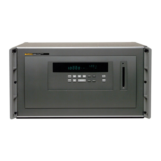
The Fluke DAQ software configures and controls up to 99 2680 Series instruments via an Ethernet connection. The software provides the means to view scan data and log it into files. In addition, Fluke DAQ software permits multiple master/slave groups to run simultaneously. - Page 22 2680A/2686A Users Manual alg46f.eps Figure 1-1. 2680A/2686A Instrument...
-
Page 23: Instrument Features And Capabilities
Number, and front panel displays such as (Only available channel monitoring, digital I/O status, and on the 2686A) totalizer count. SCAN FUNC REVIEW AUTO Mx+B ALARM LAST C F RO mV AC DC LIMIT HI x1Mk Display detail alg47f.eps Figure 1-2. 2680A/2686A Front Panel... - Page 24 2680A/2686A Users Manual REM (Remote) 11208 (Global ChannelNumber). Annunciator. Indicates the channel Indicates the Host being monitored is Computer and the 11208. This number Instrument are consists of the communicating on the MON (Monitor) instrument Base network, i.e., the Annunciator.
- Page 25 125 ms start of any scan; of 100 to 240 V ac (50/60 Hz). Trigger In input logic low triggers scanning; DC PWR (dc volts input) input is 9 to 45 V dc to power the instrument. alg60f.eps Figure 1-4. 2680A/2686A Rear Panel...
-
Page 26: Mainframe Features
2680A/2686A Users Manual Mainframe Features Trigger Input Trigger Input is an instrument connection used to trigger scans from an external source. The connection uses the rear panel Trigger In and GND (Figure 1-4). A logic low or contact closure between Trigger In and GND triggers an instrument scan if External Trigger is enabled. -
Page 27: Master Alarm
+5.0 V dc). Interval Trigger Interval Trigger is an internal software timer you can set using Fluke DAQ software. It permits scanning at regular time intervals using Interval 1. Interval 1 is in seconds, with a minimum of 0.000 (continuous scanning) and a maximum of 86400.000 (one scan every 24 hours). -
Page 28: Channel Monitoring
Channel monitoring takes place at the front panel of the instrument. Use the front panel MON key and arrow keys to select a channel for monitoring. The Fluke DAQ software also allows the selection of a channel to monitor during scanning. -
Page 29: Computed Channels
The input channels are numbered 101 to 120, 201 to 220, 301 to 320, 401 to 420, 501 to 520, and 601 to 620. The host computer configures all analog channels using the Fluke DAQ software. There are two different analog modules available for the 2680 Series instruments with up to 6 modules for any given instrument. -
Page 30: Digital I/O Module Option
Relay Output There are also 8 relays capable of switching up to 1 A or 250 V rms. Fluke DAQ software records the relay status as bits 24-31 of the DIO value. The selay status can also be displayed on the instrument front panel. -
Page 31: User Interface
Figure 1-5. DIO Connector Module User Interface Fluke DAQ is the operating software for the 2680 Series instruments. It lets you configure and operate your system through a Windows-based environment. You can install Fluke DAQ on either Windows XP, 2000 (Service Pack 3 required), or NT (Service Pack 6.0 required). -
Page 32: Operating A 2680 Series Data Acquisition System
A unique 2 digit Base Channel Number (BCN) entered at the instrument front panel identifies each 2680 Series instrument on the network. All subsequent operations refer to the instrument by BCN. Fluke DAQ supports up to 99 instruments for operation. You cannot operate an instrument from more than one host computer at a time. -
Page 33: Group Operations
Group Operations Using Fluke DAQ, you can group scan data from multiple instrument modules and sources. Fluke DAQ can record data from all sources in the group into a single .csv data file. When grouping data, one module or instrument is designated as the Master. The Master determines the times of the scans in the .csv data file. - Page 34 As a result, the maximum scan time while storing data will be slowed. Table 1-1. Channel Count vs Scan Rate 2680A/2686A Channel Rate With No Lost Data* Channel Count Module Count Typical Total Time (ms)
-
Page 35: Rs-232 Interface
Overview Host Computer Requirements Network traffic can have a significant impact on instrument throughput. More importantly, if the 2680 Series instruments cannot output the readings quickly enough, the internal memory will eventually over flow. Depending on the setting the user chose, the readings will either be written to the last location in memory or start to write over the oldest data location (the default). -
Page 36: Options And Accessories
Fluke Development Software 2680A-DLL Fluke DLL Library routines for the development of custom user software. 2680A-OPC Fluke OPC Software. Used to configure a PC to act as an OPC server and provide virtual contact with a 2680 Series instrument. 1-18... -
Page 37: Preparing For Operation
Chapter 2 Preparing for Operation Contents Page Introduction Instrument Preparation..................2-4 Unpacking and Inspecting the Instrument..........2-5 Positioning and Rack Mounting..............2-5 Connecting to a Power Source and Grounding ......... 2-5 Operating Using AC Power ..............2-6 Operating Using DC Power ..............2-7 Grounding and Common Mode Voltage.......... - Page 38 Interconnection Using 10/100BaseT (Twisted Pair) Ethernet Wiring . 2-50 Set Up Windows Networking ..............2-52 Setting Host Computer Networking Parameters........2-53 Installing Fluke DAQ Software ..............2-53 Testing and Troubleshooting................2-54 Installing and Testing the Installation............2-54 Troubleshooting Network Problems............2-58...
-
Page 39: Introduction
• Instrument and Host Computer Interconnection Connecting the host computer(s) and instruments. • Host Computer Software Installation Installing Fluke DAQ software and networking software. • Testing and Troubleshooting Testing and verifying network operation, and troubleshooting any difficulties. -
Page 40: Instrument Preparation
- 2680A - 2680A 1 2 3 4 5 6 - 2686A 1 2 3 4 5 6 - 2686A FLUKE CORPORATION MADE IN USA • www.fluke.com PATENTS PENDING FLUKE CORPORATION MADE IN USA • www.fluke.com PATENTS PENDING ETHERNET NOT FOR... -
Page 41: Unpacking And Inspecting The Instrument
You can connect the instrument to an ac power source between 100 – 240 V ac (50/60 Hz), to a dc power source between 9 and 45 V dc, or to both. Fluke guarantees equipment specifications only for 50 Hz and 60 Hz mains operation and dc operation. -
Page 42: Operating Using Ac Power
Figure 2-2. The instrument operates on any line voltage between 100 – 240 V ac without adjustment. Fluke warrants the instrument to meet specifications only at mains frequency 50 Hz and 60 Hz. Power consumption is nominally 30 watts. Be... -
Page 43: Operating Using Dc Power
A 4 amp fuse is used to protect the dc input from over current. This fuse is located inside the 2680 Series chassis on the main controller board. The fuse should only be replaced by a Fluke qualified technician with all power disconnected from the instrument. -
Page 44: Trigger Input
2680A/2686A Users Manual The ALARM/TRIGGER I/O connector (Figure 2-3) on the rear panel of the instrument provides connections to Trigger In, Trigger Out, and Master Alarm I/O lines along with common ground connections. (See the Trigger Input, Trigger Output, and Master Alarm Output sections in Chapter 1 for additional information.) The dc power connection is also on this connector. -
Page 45: Trigger Output
125 µs every time a scan begins. Use the Trigger Output to trigger other instruments via their Trigger Input connection and to interface with external equipment. You can enable or disable the Trigger Output using Fluke DAQ software. The trigger output default is OFF. See Table A-4 in Appendix A for complete specifications. -
Page 46: Master Alarm
1 second or less. Figure 2-4 shows a typical wiring connection for a group of instruments. Use the Fluke DAQ software to configure the group of instruments as described in Chapter 3 of this manual. 2-10... - Page 47 Preparing for Operation Instrument Preparation Master Instrument External trigger if used WARNING: TO AVOID ELECTRIC SHOCK GROUNDING CONNECTOR IN POWER CORD MUST BE CONNECTED MAIN SUPPLY 100V- 240V 47Hz / 63Hz 100VA MAX NO INTERNAL USER SERVICEABLE PARTS. REFER SERVICE TO QUALIFIED SERVICE PERSONNEL Other Grouped Instrument WARNING: TO AVOID...
-
Page 48: Universal Input Module Analog Connections (2620A-180)
2680A/2686A Users Manual Universal Input Module Analog Connections (2620A-180) Connections to the Universal Input Module (Figure 2-5) use the H (high) and L (low) pairs of terminals for each of the 20 analog input channels. The Universal Input Module Analog Connections are used with the PAI or FAI modules. - Page 49 Preparing for Operation Instrument Preparation STRAIN RELIEF H L H L H L H L H L H L H L H L H L H L H L H L H L H L H L H L H L alg58f.eps Figure 2-5.
- Page 50 2680A/2686A Users Manual 2-WIRE (2T) CONNECTION SOURCE (4-WIRE) SENSE (4-WIRE) Use H and L Terminals for any channel. • Channels 1 through 20 on rear panel input module (Channel 8 shown here). 4-WIRE (4T) CONNECTION SOURCE (4-WIRE) SENSE (4-WIRE) Resistance RTD Source Use H and L Terminals for two channels on rear panel input module.
-
Page 51: Shielded Wiring
Preparing for Operation Instrument Preparation Shielded Wiring Use shielded wires and sensors (such as thermocouples) in environments where electrical noise is present, and connect the wire shield to the chassis ground terminal. Also refer to Appendix B, Noise, Shielding and Crosstalk Considerations. -
Page 52: Digital I/O
2680A/2686A Users Manual 3. Loosen the wire clamp screw for the associated terminal. 4. Feed the wire into the gap between the connector body and the wire clamp. 5. Tighten the wire clamp; do not over tighten and crush the wire. -
Page 53: Totalizer Enable
Preparing for Operation Instrument Preparation When using the totalizer with time stamps in computed channels (e.g. rate calculations), the timestamp interval may vary depending on the number of active channels, number of active modules, and number of alarms. Totalizer Enable Σen is an input that can be used to enable or disable the totalizer counting capability. - Page 54 2680A/2686A Users Manual Table 2-1. Front Panel Key Descriptions Name Description Display Monitor Channel. After pressing MON, use the C B keys to select the desired channel to monitor. Pressing D for down or E up will start the monitor display automatically scrolling through the channels.
-
Page 55: Front Panel Indicators
Preparing for Operation Instrument Preparation Table 2-1. Front Panel Key Descriptions (cont.) Name Description Used when an alarm is active on the instrument. Press the ALARM button to jump into monitor mode with the “first’ (lowest )channel in alarm showing. Press ALARM again to scroll to the next channel in alarm. - Page 56 2680A/2686A Users Manual Table 2-2. Annunciator Display Descriptions Annunciator Description REVIEW Displays while reviewing the instrument parameters. (Not Used.) Indicates active communications connection with the host computer (bright display) or inactive communications (dim display). SCAN Displays while the instrument is scanning.
- Page 57 Preparing for Operation Instrument Preparation Table 2-2. Annunciator Display Descriptions (cont) Annunciator Description Displays when you monitor a channel for which the measurement value is scaled by 1,000 (kilo). Ω Displays when you monitor a channel for which the measurement function is in Ohms.
-
Page 58: Rear Panel Controls
2680A/2686A Users Manual Rear Panel Controls The rear panel has a single control: the power switch (Figure 2-10). The power switch controls both ac and dc power inputs. Power Switch Applies AC and/or DC power to the instrument. 10/100 BASE T... -
Page 59: Rear Panel Indicators
Preparing for Operation Instrument Preparation Rear Panel Indicators The rear panel has three LED indicators for the Ethernet adapter (Figure 2-11). • Transmit (XMT) Normal indication blinks when the instrument is transmitting data on the network. • Receive (RCV) Normal indication blinks when there is any network activity. Steady off means there is no network activity. -
Page 60: Front Panel Operating Procedures
To reset the configuration from the front panel, hold the MODULE button down, and then turn on power. Continue holding the MODULE button until the instrument beeps. You can accomplish the same thing using Fluke DAQ software to download a new configuration. -
Page 61: Displaying A Monitor Channel
Preparing for Operation Instrument Preparation Displaying a Monitor Channel Perform the procedure below to monitor an instrument analog channel (101 to 620) or computed channel (901 to 960). See Figure 2-12 for examples. • Channel Display When you press the MON key, the first monitor channel displayed is the channel most recently monitored. - Page 62 2680A/2686A Users Manual Monitor display for 13.758 mV DC, GCN (Global Channel Number) 05111 Monitor display for Scale Overload V AC (reading is greater than the selected range), GCN 45107 Monitor display for 234.96°F (Thermocouple), GCN 05112 (otc displays for open thermocouple) Monitor display for 23.884 FUNC (Computed Channel), GCN 05902...
-
Page 63: Displaying The Digital I/O Status
Press the left/right arrow keys to display the desired DIO line, DIO19 to DIO0. Hyphens divide the display, for example, 1111-0000-0000-0000-0000. Press the DIO key again to exit. Fluke DAQ Software can also display the Digital I/O status. Input example Toggling DIO7 between open circuit and ground results in I/O status of 1111 1111 1111 1111 1111 and 1111 1111 1111 0111 1111. -
Page 64: Displaying Relay Status
2680A/2686A Users Manual Displaying Relay Status Similar to DIO lines, there are 8 relay outputs: Rly 1 to Rly 8. The relay outputs can be statically set or associated with an alarm output. Display is in the form nnnn-nnnn with five characters in view at a time. - Page 65 Preparing for Operation Instrument Preparation Digital I/O status display for DIO line 19 (for example 1111-0000-0000-0000-0000) Digital I/O status display for DIO line 16 (for example 1111-0000-0000-0000-0000) Relay status display for Relay 1 (for example 1111-0000) Totalizer status display for the high digits (for example 4294967295) Totalizer status display for the low digits (for example 4294967295) Figure 2-13.
-
Page 66: Displaying The Totalizer Status
Press an up/down arrow key to advance to the totalizer display. The 10 digits display in a five digit tot:HI count and five digit tot:LO count. Press the DIO key again to exit. Fluke DAQ software also provides a display of the totalizer status. -
Page 67: Reviewing And Setting The Base Channel Number
116. (See Figure 2-14 for examples.) • BCN Range The BCN can be any number from 01 to 99. If you plan to install Fluke DAQ software for isolated network operation, each instrument on the network must have a unique BCN. •... - Page 68 2680A/2686A Users Manual REVIEW Communications display for reviewing the Base Channel Number (BCN) Communications display for setting the BCN Base Channel Number display for setting the BCN 10s digits (for example, 45) REVIEW Base Channel Number display for reviewing the BCN number (for example, 45) Front Panel display for a instrument with BCN 45 Figure 2-14.
-
Page 69: Reviewing And Setting The Line Frequency
Preparing for Operation Instrument Preparation Reviewing and Setting the Line Frequency Perform the procedure in Table 2-9 to review or set the line frequency. Line frequency selection allows the instrument to optimize internal circuitry for best accuracy. (See Figure 2-15 for examples.) •... - Page 70 2680A/2686A Users Manual REVIEW Communications display for reviewing the line frequency Communications display for setting the line frequency Line frequency display for setting the line frequency to 60 Hz Line frequency display for setting the line frequency to 50 Hz...
-
Page 71: Reviewing And Setting The Network Type
(See Figure 2-16 for examples.) If you use Fluke DAQ software for isolated network operation and set the instruments’ network type to isolated, you do not need to know or set IP addresses for your instruments. - Page 72 2680A/2686A Users Manual REVIEW Communications display for reviewing the network type Communications display for setting the network type Network display for setting the network type to isolated Network display for setting the network type to general REVIEW Network display for reviewing the network type (isolated network) Figure 2-16.
- Page 73 Preparing for Operation Instrument Preparation If you set Fluke DAQ Software for general network operation, you must set the network type of each instrument to general. You will need to enter an IP address, and possibly a socket port, subnet mask and gateway address into each instrument.
- Page 74 2680A/2686A Users Manual REVIEW Communications display for reviewing the network type Communications display for setting the network type Network display for setting the network type to general Socket Port display for setting the first digit (for the example 04369) Socket Port display for setting the second digit (for the example 04369) Figure 2-17.
- Page 75 Preparing for Operation Instrument Preparation IP address display for setting an IP:0 digit (for example, 129:196:152:101) IP address display for setting an IP:1 digit (for example, 129:196:152:101) IP address display for setting an IP:1 digit (for example, 129:196:152:101) IP address display for setting an IP:2 digit (for example, 129:196:152:101) IP address display for setting an IP:3 digit (for example, 129:196:152:101) Figure 2-17.
-
Page 76: Reviewing And Setting The General Network Socket Port
2680A/2686A Users Manual Reviewing and Setting the General Network Socket Port Perform the procedure in Table 2-12 to review or set the general network Socket Port (1024 to 65535). The default port is 04369. In order to communicate with each other, a host computer and an instrument must use the same socket port number. -
Page 77: Reviewing And Setting The General Network Ip Address
Preparing for Operation Instrument Preparation Reviewing and Setting the General Network IP Address Perform the procedure in Table 2-13 to review or set the general network Internet Protocol (IP) address. (See Figure 2-17 for examples.) • General Network IP Address Enter the IP Address supplied by your network administrator for each BCN. -
Page 78: Reviewing And Setting The Subnet Mask And Default Gateway
2680A/2686A Users Manual Reviewing and Setting the Subnet Mask and Default Gateway If communication between the host computer and the 2680 Series passes through a router or gateway, you must set the subnet mask and default gateway address on both the host computer and the instrument. Get this information from your network administrator. - Page 79 Preparing for Operation Instrument Preparation the network number), the data is sent through the gateway to reach the host The network number of the instrument must match that of the gateway. For example, if the gateway IP address is 129.196.180.93, and the subnet mask is 255.255.255.0, the network number is 129.196.180.0, and the instrument IP address must be in the range 129.196.180.1 to 129.196.180.254.
-
Page 80: Viewing The Instrument Ethernet Address
2680A/2686A Users Manual Viewing the Instrument Ethernet Address Perform the procedure in Table 2-15 to view the Instrument Ethernet address. (See Figure 2-18 for examples.) The network administrator must know the instrument Ethernet address when the instrument operates on a general network. You do not need this information when you operate the instrument on an isolated network. - Page 81 Preparing for Operation Instrument Preparation REVIEW Communications display for viewing the instrument Ethernet address REVIEW Ethernet address display for viewing byte 0 (for example 00-80-40-12-34-56) REVIEW Ethernet address display for viewing byte 2 (for example 00-80-40-12-34-56) REVIEW Ethernet address display for viewing byte 4 (for the example 00-80-40-12-34-56) REVIEW Ethernet address display for viewing byte 5 (for example 00-80-40-12-34-56) Figure 2-18.
-
Page 82: Reviewing And Setting Pc Card Options
2680A/2686A Users Manual Reviewing and Setting PC Card Options PC ATA flash memory cards provide a convenient way to store information. Only a single stored configuration and a single set of scan data can be stored on the card. The configuration file contains instrument configuration information that can be used to copy configuration information from one instrument to another. -
Page 83: Host Computer And Network Preparation
PC. The card data is stored in a proprietary data format and must be converted to a text or .csv format for reading. The Fluke DAQ software can convert the data from the card in the PC or in the 2686A. - Page 84 2680A/2686A Users Manual Install Ethernet Ethernet Card Adapter Card Interconnect Host Computers Instruments Instrument Set up Windows 2000 Windows or higher Install Fluke DAQ Software Fluke DAQ for Windows alg02f.eps Figure 2-19. Preparing for Network Operation 2-48...
-
Page 85: Instrument And Host Computer Interconnection
Preparing for Operation Host Computer and Network Preparation Instrument and Host Computer Interconnection You may interconnect 2680 Series instruments and host computer(s) with 10/100BaseT (twisted pair) wiring. If your site is already wired, you will probably use the wire in place. If your site is not wired, you are connecting your instrument directly to your host computer. -
Page 86: Interconnection Using 10/100Baset (Twisted Pair) Ethernet Wiring
2680A/2686A Users Manual Interconnection Using 10/100BaseT (Twisted Pair) Ethernet Wiring The instruments support connection via twisted pair Ethernet, usually in conjunction with a "hub" for multiple instruments (See Figure 2-21). Take care that you use twisted pair wires designed for 10/100BaseT network use (phone cables will not work). - Page 87 Preparing for Operation Host Computer and Network Preparation The typical general network configuration uses 10/100BaseT Twisted Pair Ethernet for interconnection (shown). Connect to RJ-45 10/100BaseT Port Instrument 1 Host Computer 1 10/100BaseT Twisted-Pair Ethernet Hub (Not Supplied) Instrument 2 Instrument 3 Host Computer 2 RJ-45...
-
Page 88: Set Up Windows Networking
2680A/2686A Users Manual Set Up Windows Networking To establish Ethernet communication in your host computer, you must do the following: • Install a driver for the adapter • Install TCP/IP protocol stack • Set host computer networking parameters This section discusses installing the adapter driver and the TCP/IP protocol stack. -
Page 89: Setting Host Computer Networking Parameters
This section discusses how to set your host computer networking parameters after you install your adapter and set up the network. If you plan to use Fluke DAQ software for general network operation, and you are just now enabling networking, you must set the host computer’s IP address, subnet mask, and possibly its default... -
Page 90: Testing And Troubleshooting
Appendix I for additional troubleshooting information. Installing and Testing the Installation This test procedure includes opening Fluke DAQ software, configuring and verifying communications with the instrument. Refer to Chapter 3 for detailed instructions for configuring and communicating with instruments using Fluke DAQ software. - Page 91 Testing and Troubleshooting To install a instrument and test the installation 1. Double-click the icon on your desktop to start Fluke DAQ. 2. Specify basic settings in the Fluke DAQ Application dialog window. alg102s.bmp The dialog box entries include: Configuration file Click the button to load an existing configuration file.
- Page 92 The Base Channel number auto-increments when you add instruments. alg104s.bmp Note Fluke DAQ also supports 2640A and 2645A NetDAQ instruments but some of the Fluke DAQ configuration dialogs may differ from those for the 2680 Series. 2-56...
- Page 93 Preparing for Operation Testing and Troubleshooting 5. In the TreeView panel, select the instrument you just added. alg105s.bmp 6. Set the IP Address on the Instrument Settings dialog if using General Network Type (IP Address is disabled if Isolated network is used). Other fields are optional.
-
Page 94: Troubleshooting Network Problems
Troubleshooting Network Problems Review the troubleshooting information below to help locate any network problems. Table 2-16 summarizes network messages reported by Fluke DAQ software for Windows. Table 2-17 is a summary of how to use the Ethernet LED indicators on the instrument to identify network problems. - Page 95 General Network mode. computer on network • Socket port wrong in Fluke DAQ (General) • IP address in Fluke DAQ in use by another instrument • PC network adapter set to same IP address as the instrument 2680 Series hardware set up •...
- Page 96 2680A/2686A Users Manual Table 2-16. Identifying Network Problems (cont) Symptom/Error Reason/Possible Cause Timeout happened during network operation Cabling problem • Not connected • Wrong cable (10/100BaseT direct connection) • Adapter auto-sensing wrong network speed • Adapter or driver set up to wrong network speed •...
- Page 97 Preparing for Operation Testing and Troubleshooting Table 2-17. Ethernet Indicators Indicator Description Instrument (10/100BaseT) XMT (red) Transmit Normal indication blinks when the instrument is transmitting data on the network. RCV (red) Receive Normal indication blinks when there is any network activity.
- Page 98 2680A/2686A Users Manual 2-62...
-
Page 99: Using Fluke Daq Software
Trend Dialog ..................... 3-13 Alarm Dialog..................... 3-13 Mail and Web Settings Dialogs..............3-13 Managing Your Network Using Fluke DAQ........... 3-14 Inserting and Configuring an Instrument ..........3-14 Inserting and Configuring a Module ............3-19 Inserting and Configuring a Channel ............3-23 Configuring a Computed Channel............. - Page 100 Selecting a Master for a Data Group............3-47 Advanced Data File Configuration ............3-47 Real-time Data File Creation ..............3-53 Main Window Advanced Settings..............3-55 Using Fluke DAQ System Security Features ..........3-56 Configuring Web and Alarm Mail Settings ............ 3-58...
-
Page 101: Introduction
Using Fluke DAQ Software Introduction Introduction Fluke DAQ software provides a graphical user interface (GUI) to the 2680 Series and NetDAQ data acquisition products. You can use Fluke DAQ software to easily perform the following: Note Fluke DAQ supports the NetDAQ models 2640A and 2645A as well as the 2680A and 2686A. -
Page 102: Installing Fluke Daq Software
3. The installation program creates a shortcut on the your desktop when the installation is complete. Double-click the shortcut to start Fluke DAQ. Note You may need to reboot your computer after you install the Fluke DAQ software. The following directories and files are installed on your PC. alg100s.bmp The Fluke DAQ subdirectories contain the following information: Alarm Collected alarm data and format information. -
Page 103: Understanding The User Interface
Config Saved configuration files. Data Scan data files. Understanding the User Interface Fluke DAQ software has a standardized and easy to use interface. This section explains the components of the interface. Fluke DAQ Main Window The Fluke DAQ main window contains a workspace area, toolbar, and other controls to add instruments and configure your network. -
Page 104: Using The Toolbar
Users Manual Using the Toolbar A toolbar appears on all of the Fluke DAQ dialogs. Use the toolbar buttons to add and configure 2680 Series instruments and to navigate through the Fluke DAQ application. Each button on the toolbar has a tool tip that identifies the button function. - Page 105 Ack command (Last Alarm or All Alarms) in the Alarms dialog. Web and Alarm Mail Settings button. Used to enter Fluke DAQ web configuration information and to configure Fluke DAQ to send e-mail messages reporting alarm condition.
-
Page 106: Understanding The Workspace Area
2680A/2686A Users Manual Understanding the Workspace Area The Workspace Area consists of a network TreeView and a set of buttons. Use the Workspace Area to: • Open, Save, and Create configuration files. You can also use the Save As button to rename an existing configuration file. -
Page 107: Configuration Dialogs
TreeView. Instrument Configuration Dialog You can configure your 2680 Series or NetDAQ instruments using the Fluke DAQ Instrument Configuration dialog. This dialog appears when you select an instrument in the TreeView. You can use the Configuration dialogs to: •... -
Page 108: Module Configuration Dialog
Highlight the Computed Channel icon and click on the Insert button. Detailed instructions for using the Configuration dialogs is provided later in this Chapter. Note Computed channel values are only updated on the 2680A and 2686A instruments when scanning is active. 3-10... -
Page 109: Communication Dialogs
Understanding the User Interface Communication Dialogs The Communication dialogs display the communication status of connected network components and allow you to interact with those components. Fluke DAQ uses the following Communication dialogs. Main Communication Dialog You can use the Main Communication dialog to start and stop scanning on all instruments at the same time. -
Page 110: Communications Icons
Security Dialogs You can use the system security features to protect instrument configuration information. The system security feature allows the administrator to add and remove Fluke DAQ users, allow other users to configure instruments, and to change user passwords. 3-12... -
Page 111: Trend Dialog
Mail and Web Settings Dialogs You can use the Web and Alarm Mail Settings dialog to enter Fluke DAQ web configuration information and to configure Fluke DAQ to send e-mail messages reporting alarm condition. -
Page 112: Managing Your Network Using Fluke Daq
2680A/2686A Users Manual Managing Your Network Using Fluke DAQ The following procedures provide detailed instructions for using Fluke DAQ to: • Insert and configure instruments, modules, channels, and computed channels • Start a scan • View scan data • View alarms... - Page 113 Isolated if the PC is connected directly to the instrument or General if the instrument is part of a network. Port Number 4369 is the default port number. Fluke recommends that you use the default port number. Enable Data Simulation If enabled, data is simulated (for demonstration purposes) and the software does not actually control the instruments.
- Page 114 BCN of the instruments. alg104s.bmp Note Fluke DAQ also supports 2640A and 2645A NetDAQ instruments. Some of the Fluke DAQ configuration dialogs may differ from those for the 2680 Series. 5. In the TreeView panel, select the instrument you just added. alg105s.bmp...
- Page 115 Using Fluke DAQ Software Managing Your Network Using Fluke DAQ 6. Set the IP Address on the Instrument Settings dialog if using a General Network Type (IP address is disabled if you are using an Isolated Network Type) . Other fields are optional. You may need to contact your network support staff to determine the IP Address.
- Page 116 2680A/2686A Users Manual Monitor Channel Select a channel measurement to display on the instrument front panel. You can also choose to increment up or down through all active channels automatically. Default is None. Scan Parameters Parameters you can set to start, stop, and save scan data. Select Start Scan on Power Up for stand-alone operation or to automatically start scanning after a power loss.
-
Page 117: Inserting And Configuring A Module
Using Fluke DAQ Software Managing Your Network Using Fluke DAQ Inserting and Configuring a Module To insert and configure a module 1. Highlight an instrument in the TreeView panel and click the Insert button. alg107s.bmp 2. Specify the number and type of modules you want to insert in the Module dialog box. - Page 118 2680A/2686A Users Manual 3. Click Ok. The modules are added to the instrument and appear in the TreeView panel. alg109s.bmp 4. Select one of the analog modules you inserted and the Analog Module settings dialog appears. alg110s.bmp 3-20...
- Page 119 Using Fluke DAQ Software Managing Your Network Using Fluke DAQ The dialog box entries include: Interval Trigger Uses the interval timer (interval 1 timer) to set the scan rate for normal operation in a module. The interval is user settable.
- Page 120 2680A/2686A Users Manual Note For the NetDAQ 2640A and 2645A, the scan trigger, intervals, reading rate, and drift correction are set on the Instrument Configuration dialog instead of the Module settings dialog. Conditional scan storage is not available on the NetDAQ instruments.
-
Page 121: Inserting And Configuring A Channel
Using Fluke DAQ Software Managing Your Network Using Fluke DAQ Note For the NetDAQ 2640A and 2645A, the totalizer debounce check box is set on the Instrument Configuration dialog. Totalizer start count and direction are not available on the NetDAQ. - Page 122 2680A/2686A Users Manual 3. Click Ok. The channels are added to the module and appear in the TreeView panel. alg114s.bmp 4. Select a channel and the Module settings dialog appears. alg115s.bmp The dialog box entries include: CH # XX-YYY. The first two digits identify the chassis BCN (01-99). The next digit identifies the module (1-6), and the last two digits identify the channel (1-20).
- Page 123 1.15 would result in a reading of 100(1.15)+50=165. Input and Scaled Range You can enter the Input and Scaled ranges and click the Calculate M and B from Ranges button to have and Fluke DAQ calculate the M and B values. 3-25...
-
Page 124: Configuring A Computed Channel
2680A/2686A Users Manual Configuring a Computed Channel Computed channels provide a means to calculate values based on measurements. For example, if Channel 1 measures dc V and Channel 2 measures dc I, you could use a computed channel to calculate instantaneous power (Channel 1 x Channel 2). - Page 125 Using Fluke DAQ Software Managing Your Network Using Fluke DAQ 3. Click Ok. The computed channels are added and appear in the TreeView panel. alg118s.bmp 4. Select a computed channel and the Computed Channel settings dialog appears. alg119s.bmp 3-27...
- Page 126 (Low) or rises above a high alarm value (High). A Band alarm type generates an alarm when the measurement value is between the two alarm limit values. Fluke DAQ records all alarm conditions in an alarm database. Each of the two Alarm limits (one for the Band type alarm) has a Digital Output button to select Digital or relay outputs that go active when an alarm is generated from the alarm limit.
-
Page 127: Configuring Multiple Channels
Input or Scaled Range You can enter the Input and Scaled range and press the Calculate M and B from Ranges button to have Fluke DAQ calculate the M and B values. Configuring Multiple Channels You can change or set configurations using multiple selections in the TreeView window. -
Page 128: Using Equations With Computed Channels
2680A/2686A Users Manual Using Equations with Computed Channels If you select the Computed Channel Equation function, and press the Equation button, the Expression entry dialog appears. alg120s.bmp The following is a list of the valid notations in an expression. Axxx Alarm on/off (Boolean value of 1 or 0) - Page 129 Using Fluke DAQ Software Managing Your Network Using Fluke DAQ Every expression must refer to at least one channel or other measurement value such as TOT. For example, the expression C101+1 adds one to the measured value of channel 101, while C102**2 produces the square of the channel 102 value.
-
Page 130: Starting A Scan
Starting a Configuration Scan To start a configuration scan 1. Click the on the Fluke DAQ toolbar and highlight the top or root item in the TreeView panel. 2. Click to start the scan on all instruments. Click to stop the scan. -
Page 131: Starting An Instrument Scan
There is no need to retrieve the scan data manually. However, if scanning is started from the 2680A or 2686A front panel or if scanning continues after the software or computer is shut down, the scan data is stored in the instrument’s internal scan queue memory. -
Page 132: Viewing And Resetting The Totalizer
2680A/2686A Users Manual Viewing and Resetting the Totalizer The Totalizer Count current value on the Instrument communication screen is updated after each scan. Press the to set the totalizer to zero or to the start count value set in the totalizer configuration. -
Page 133: Getting Pc Card Scan Data
Advanced Data File Configuration described in this chapter, except that only this single 2686A unit is shown. If Insert Labels is used, the configuration in Fluke DAQ for this instrument needs to be the same as the configuration of the 2868A when the scan data was collected, or the labels may not be correct. -
Page 134: Starting Spy
When you click the Ok button, Fluke DAQ will try to create the data file. When creating the file, if Fluke DAQ detects a file on disk with the same name that Fluke DAQ is trying to generate, Fluke DAQ will add data to the file or rename it depending on the File Size Control configuration. - Page 135 Using Fluke DAQ Software Managing Your Network Using Fluke DAQ alg123s.bmp 3. Click to start Spy. Click to stop Spy. 3-37...
-
Page 136: Viewing Module Measurement Data
Modules that are not scanning display question marks for the channels. NC indicates that a channel is not configured. To view module measurement data 1. Click the on the Fluke DAQ toolbar. 2. Highlight a module in the TreeView panel and the module measurement data appears. alg124s.bmp... -
Page 137: Using The Digital I/O Points Communication Dialog
Using Fluke DAQ Software Managing Your Network Using Fluke DAQ Using the Digital I/O Points Communication Dialog You can use the Digital I/O Points Communication dialog to set any of the 8 relays or 20 DIO pins. You can also view status of all of the relays and DIO pins and set or clear IO bits and relays. -
Page 138: Using Trend To View Collected Data
Trend window are replaced with ???????. Channels that are still scanning will continue to show the latest data. To use the trend feature 1. Click the button on the Fluke DAQ toolbar and the Trend dialog appears. alg126.bmp 3-40... - Page 139 Using Fluke DAQ Software Managing Your Network Using Fluke DAQ The dialog box entries include: Type Specify On Line or History scan view. History view shows the last set of data displayed with the pens. Zoom to expand or compress the time interval you are viewing.
- Page 140 When you click the Ok button, Fluke DAQ will try to create the data file. When creating the file, if Fluke DAQ detects a file on disk with the same name that Fluke DAQ is trying to generate, Fluke DAQ will add data to the file or rename it depending on the File Size Control configuration.
-
Page 141: Changing The Trend Chart Display
Using Fluke DAQ Software Managing Your Network Using Fluke DAQ Changing the Trend Chart Display To change the Trend chart display • The Trend Setting dialog appears when you double-click on the chart screen. Use the Trend Settings dialog to change the location of the upper and lower boundary points and the scaling seen on the chart for each of the plot pens you are using. -
Page 142: Viewing Alarms
When a channel has two alarms, only one alarm can be active at a time. If one alarm becomes active and then a second alarm becomes active, Fluke DAQ will acknowledge the first alarm and show the second alarm as active. - Page 143 Using Fluke DAQ Software Managing Your Network Using Fluke DAQ The dialog box entries for On Line include: Type Specify On Line or History alarm view. Click the appropriate button to acknowledge the Last Alarm or All Alarms. Alarm Instrument Filters Choose to view alarms from a select set of instruments, modules, and channel.
-
Page 144: Configuring Data Files
The data in this database may be exported to an Excel compatible file in the Trend window. By default, Fluke DAQ adds all data from all the instruments into a single .csv data file when real-time data file creation is enabled. Use the Advanced Data File Configuration feature if you don’t want to save all the data, or want to... -
Page 145: Selecting A Master For A Data Group
Use the Advanced Data File Configuration dialog to create multiple groups of data files. The configuration performed in the Data File Configuration window is stored in the group that has the same name as the Fluke DAQ configuration file. 3-47... - Page 146 2680A/2686A Users Manual To use the Advanced Data File Configuration feature • Click the button on the Data File Configuration dialog and the Advanced Data File Configuration dialog appears. alg141s.bmp The dialog box entries include: Data Group Name Name of the current active group. This box can be used to show any group names used with the configuration by selecting the down arrow.
- Page 147 Inserts the new group. Cancel Closes the window without inserting a new configuration. Note Fluke DAQ displays an error message if the you enter the name of an existing group or a blank name. Rename Click the button to change the name of an existing data group. When you click the Rename button, the Rename Group dialog appears.
- Page 148 2680A/2686A Users Manual alg143s.bmp Note Fluke DAQ displays an error message if the you enter the name of an existing group or a blank name. Remove Click the button to remove an existing group (only the group is deleted, any data file created by the group remains). When you click this button, a confirmation box appear.
- Page 149 After renaming the file, Fluke DAQ creates a new data file with the original data file name. For example, when the specified file size control criterion is reached, the file “MyData.csv”...
- Page 150 40 hours and 70 minutes File Size Size 50 MB This parameter represents the file size. If the file size is exceeded, Fluke DAQ generates a new file. Number of Amount 65000 lines A new file will be created every time that the...
-
Page 151: Real-Time Data File Creation
Data Groups that conflict will not be started, but the other groups will be created and the scan will start normally. If Fluke DAQ detects a file on the disk with the same name that Fluke DAQ is trying to generate, Fluke DAQ will add data to the file or rename it depending on the File Size Control configuration. - Page 152 • Click Yes, and Fluke DAQ will start the scan for all the instruments in the Data Group. • Click No, and Fluke DAQ will start the scan and create data files for Data Groups that have a single instrument associated with them.
-
Page 153: Main Window Advanced Settings
30 seconds. The default is not selected, which means scanning will not stop automatically. Do not ask to start slaves Selecting Do not ask to start slaves prevents Fluke DAQ from asking to start other instruments grouped with a Master when the Master starts scanning. The default is not selected. -
Page 154: Using Fluke Daq System Security Features
Interval 3 is the interval the instrument checks for alarms during longer intervals between scans. PAI/2640 Interval 3 is the alarm checking interval for 2680A PAI modules and NetDAQ 2640A. You can set Interval 3 to a maximum of 1000 seconds and a minimum interval of 0.500 seconds for the PAI/2640. - Page 155 Password buttons and the Enable Configuration check box are visible. Check the Enable Configuration box to give a user permission to change the configuration of instruments using the Fluke DAQ software. Leaving the checkbox unchecked prevents the user from changing configuration settings.
-
Page 156: Configuring Web And Alarm Mail Settings
2680A/2686A Users Manual Configuring Web and Alarm Mail Settings You can use the Web and Alarm Mail Settings dialog to enter Fluke DAQ web configuration information and to configure Fluke DAQ to send e-mail messages reporting alarm condition. The Web Settings portion of dialog is used to specify a URL where scanned values from your 2680 Series or NetDAQ instrument will be sent. - Page 157 The address where Fluke DAQ web files will be stored on the Internet. Fluke DAQ fills in the field with the first IP address found on the PC. The DHCP note above also applies to this field. In addition, the Web files can be put on a separate Web server, in which case this field should be the URL for that server.
- Page 158 2680A/2686A Users Manual SMTP Server IP Address SMTP server name or IP address. SMTP is the Simple Mail Transfer Protocol, a protocol for sending e-mail messages between servers. Originator E-Mail Address Sender e-mail address. POP 3 Server IP Address POP 3 name or IP Address. POP is the Post Office Protocol, used to retrieve e-mail from a mail server.
-
Page 159: Maintenance
Accuracy Performance Tests ................4-13 Master Alarm Output Tests ............... 4-14 RS-232 Master Alarm Output Test ............4-14 Fluke DAQ Master Alarm Output Test..........4-14 Trigger Input Tests ..................4-15 RS-232 Trigger Input Test ..............4-15 Fluke DAQ Trigger Input Test ............. 4-15 Trigger Output Tests ................. - Page 160 RS-232 Totalizer Count and Debounce Test........4-32 Fluke DAQ Totalizer Count Test ............4-33 Fluke DAQ Totalizer Count and Enable Test ........4-33 Fluke DAQ Totalizer Count and Direction Test ........4-34 Fluke DAQ Totalizer Count and Debounce Test ......... 4-34 Calibration.......................
-
Page 161: Introduction
If the error persists and you intend to repair the instrument yourself, refer to the Service Manual (PN 1883791). Otherwise, package the instrument securely (using the original container, if available), and mail it to the nearest Fluke Service Center. Include a description of the problem. Fluke assumes no responsibility for damage in transit. - Page 162 2680A/2686A Users Manual No channels will be configured and the instrument will not scan until the proper modules are installed or the configuration is changed to match the modules loaded. Stand alone scanning using a PC card has a similar restriction.
- Page 163 Maintenance Self-Test Diagnostics and Error Codes Table 4-1 Self-Test Codes (continued) Self-Test Code Description Module 2 reference balance measurements unreasonable Module 2 overload detection failed Module 2 open thermocouple detection failed No module self-test errors Module 3 calibration constants corrupt Module 3 calibration procedures incomplete Module 3 A/D failure Module 3 zero offset measurement unreasonable...
-
Page 164: Cleaning
2680A/2686A Users Manual Table 4-1 Self-Test Codes (continued) Self-Test Code Description Module 6 A/D failure Module 6 zero offset measurement unreasonable Module 6 reference balance measurements unreasonable Module 6 overload detection failed Module 6 open thermocouple detection failed PAI expected in slot 1... -
Page 165: Ac Fuse Replacement
Maintenance AC Fuse Replacement AC Fuse Replacement The instrument uses a 1/2 ampere, 250 V, slow blow line fuse in series with the mains power supply. To replace the fuse, refer to Figure 4-1 and the following procedure: XWWarning To avoid electrical shock, do not operate the instrument without the cover properly installed. - Page 166 2680A/2686A Users Manual Fuse Compartment alg66f.eps Figure 4-1. Replacing the Fuse...
-
Page 167: Dc Fuse Replacement
DC Fuse Replacement DC Fuse Replacement The 2680A/2686A instruments use a 4 ampere, 125 V, slow blow fuse in series with the dc supply “+” input. This fuse is mounted on the main controller board inside the chassis. Because of potential high voltages, this fuse should only be replaced by a Fluke qualified technician. - Page 168 2680A/2686A Users Manual 2. Connect the 5700A to Channel 1 of the First Module When testing each module, connect a cable from the Output VA HI and LO connectors of the 5700A to the Universal Input module terminals for channel 1 be certain to connect the 5700A HI to terminal H and LO to terminal L.
-
Page 169: Initializing The Performance Test Setup
Maintenance Performance Test Unshielded Twisted Pair Cable WITH RX AND TX LINES REVERSED 10/100BaseT RJ-45 Ethernet Ports RJ-45 10/100BaseT Outlets (Typical) Patch Cord RJ-45 Host Interface Instrument Computer 1 (Typical) 10/100BaseT Direct Connection alg04f.eps Figure 4-2. Performance Test Setup Initializing the Performance Test Setup Complete the following procedure to initialize the performance test setup. - Page 170 Press the ENTER key. 3. Apply Host Computer Power Apply power to the host computer. 4. Open Fluke DAQ Software You can use Start | Programs, double-click on a setup file shortcut on the Windows desktop, or double-click on a setup file name in the Windows Explorer or File Manager.
-
Page 171: Accuracy Performance Tests
The tests for the Master Alarm output, Trigger Output, Trigger Input, and DIO signal lines can either be tested using Fluke DAQ software or using commands through the RS-232 port. For the RS-232 tests, you will also need to use a program such as HyperTerminal to perform the test. -
Page 172: Master Alarm Output Tests
Alarm test lead, referenced to the GND test lead, to check if the voltage is greater than +3.8 V dc. 3. Verify Configuration Channel 1 for V dc In Fluke DAQ, verify channel 1 is configured for V dc, 3 V range. -
Page 173: Trigger Input Tests
External Trigger with an Interval 2 of 1 second. Be sure Interval Trigger and Alarm Trigger are not enabled. 2. Verify Configuration Channel 1 for V dc In Fluke DAQ, verify channel 1 is configured for V dc, 3 V range. -
Page 174: Fluke Daq Trigger Output Test
1. Configure Interval Trigger Using the Fluke DAQ software, configure the scan parameters for Interval Trigger with an Interval 1 of 1 second. 2. Verify Configuration Channel 1 for V dc In Fluke DAQ, verify channel 1 is configured for V dc, 3 V range. -
Page 175: Volts Dc Accuracy Test (Fai Module)
Measurement accuracy applies to all channels, not just the channel used for the test. 1. Configure Channel 1 for V dc Using the Fluke DAQ software, configure channel 1 for V dc, 90 mV range. 2. Open Spy Open the Spy window under the Configuration dialog. -
Page 176: Volts Ac Accuracy Test
PAI and FAI modules. Measurement accuracy applies to all channels, not just the channel used for the test. 1. Configure Channel 1 for V ac Using the Fluke DAQ software, configure channel 1 for V ac, 300 mV range. 2. Open Spy Open the Spy window under the Configuration dialog. -
Page 177: Frequency Accuracy Test
FAI modules. Measurement accuracy applies to all channels, not just the channel used for the test. 1. Configure Channel 1 for Frequency Using the Fluke DAQ software, configure channel 1 for frequency. There is no range selection for frequency as all frequency measurements use auto-ranging. -
Page 178: Analog Channel Integrity Test
The following procedure tests the integrity of each analog channel (2 to 20) to verify each analog channel is capable of making measurements. 1. Configure Channel for Ohms Using the Fluke DAQ software, configure channels 2 (then 3, then 4, etc. as this step is repeated) to 20 for Ohms 2W, 300 range [PAI] or 30 k range [FAI]. -
Page 179: 2-Wire Resistance Accuracy Test (Pai) - Optional
Decade Resistance Source. Tables are provided for both connections. 2. Configure Channel 1 for Ohms In Fluke DAQ, configure channel 1 for Ohms-2W, 300 range. 3. Open Spy Open the Spy window under the Configuration dialog. -
Page 180: 2-Wire Resistance Accuracy Test (Fai Module) - Optional
Decade Resistance Source. Tables are provided for both connections. 2. Configure Channel 1 for Ohms In Fluke DAQ, configure channel 1 for Ohms 2W, 30 k range. 3. Open Spy Open the Spy window under the Configuration dialog. - Page 181 Maintenance Accuracy Performance Tests Resistance Range* Decade Resistor Minimum Reading Maximum Reading Short Circuit (Zero) 700 Ω 30 kΩ 1 kΩ 30 kΩ 29 kΩ 29.681 kΩ 30.019 kΩ 300 kΩ 290 kΩ 289.07 kΩ 292.63 kΩ 3 MΩ 2.9 MΩ 2.8607 MΩ...
-
Page 182: 4-Wire Resistance Accuracy Test (Pai Module)
Decade Resistance Source. Tables are provided for both connections. Refer to Figure 4-5 for the 5700A 4-wire connections. 2. Configure Channel 1 for Resistance In Fluke DAQ, configure channel 1 for Ohms 4W, 300 range. 3. Open Spy Open the Spy window under the Configuration dialog. - Page 183 Maintenance Accuracy Performance Tests 4-Wire (4W) Connection 13 14 15 16 17 18 19 20 SOURCE H L H L H L H L H L H L H L H L H L H L (4-WIRE) Input Module SENSE H L H L H L H L H L H L H L H L H L H L (4-WIRE) 5700A, Decade Resistance Box...
- Page 184 2680A/2686A Users Manual 13 14 15 16 17 18 19 20 SOURCE H L H L H L H L H L H L H L H L H L (4-WIRE) INPUT MODULE SENSE H L H L H L H L H L H L H L H L H L...
- Page 185 Maintenance Accuracy Performance Tests 4. Verify Accuracy Configure the Decade Resistance Source for the output values below and verify the Spy window measurement is between the minimum and maximum values. Change the channel 1 range as required (see Step 2). Resistance Range Decade Resistor Minimum Reading...
-
Page 186: 4-Wire Resistance Accuracy Test (Fai Module)
Decade Resistance Source. Tables are provided for both connections. Refer to Figure 4-5 for the 5700A 4-wire connections. 2. Configure Channel 1 for Resistance In Fluke DAQ, configure channel 1 for Ohms 4W, 300 range. 3. Open Spy Open the Spy window under the Configuration dialog. -
Page 187: Digital Input/Output Tests
Maintenance Accuracy Performance Tests Resistance Range 5700A Minimum Reading Maximum Reading 300 Ω 0 Ω 0.1 Ω Short Circuit (Zero) 300 Ω 190 Ω 189.86 Ω 190.14 Ω 0 Ω 1.0 Ω 3 kΩ Short Circuit (Zero) 3 kΩ 1.9 kΩ 1.8986 kΩ... -
Page 188: Fluke Daq Digital Input/Output Test
Fluke DAQ Digital Input/Output Test 1. Open Communication Dialog Use the Communication dialog in Fluke DAQ for this test. Click on the DIO module icon in the TreeView display to see the DIO settings. The DIO dialog will only work if the DIO module is installed in the instrument and has been inserted using the Configuration dialog. -
Page 189: Totalizer Tests
(Σ). Connect the DIO channel 0 signal line to the totalizer enable line Σen) in the connector module. If you are using Fluke DAQ to perform the totalizer tests, select the DIO from TreeView in the Configuration dialog. In the DIO Configuration dialog, Set the start count in the DIO Configuration dialog to 0, deselect debounce (if selected), and select direction as up. -
Page 190: Rs-232 Totalizer Count And Direction Test
2680A/2686A Users Manual 1. Initialize Totalizer to 0 Initialize the totalizer to 0 with the TOTINIT command. 2. Set DIO Set DIO 0 to 1 (on) to disable the totalizer. 3. Reconnect Signal Generator Reconnect the signal generator. 4. Verify Totalizer Count Verify that the totalizer count stays at 0. -
Page 191: Fluke Daq Totalizer Count Test
Testing of the Digital Input/Output signal lines can be done through the RS-232 port (using HyperTerminal or other communication program) or through the Fluke DAQ software. Either method can be used. The Digital Input/Output Test checks the 20 Digital I/O lines through the Digital I/O connector module for correct operation. -
Page 192: Fluke Daq Totalizer Count And Direction Test
2680A/2686A Users Manual Fluke DAQ Totalizer Count and Direction Test 1. Configure DIO In the Configuration dialog, select the DIO from TreeView. In the DIO Configuration dialog, set the start count to 0, deselect debounce (if selected), and select direction as down. -
Page 193: Calibration
Maintenance Calibration Calibration Note Refer to the Service Manual (PN 1883791) for calibration procedures. The instrument must be stabilized in an environment with an ambient temperature of 22 °C to 24 °C and a relative humidity of less than 70%, and must have been powered at least 30 minutes prior to calibration. -
Page 194: Service
If the problem cannot be remedied, send the instrument, postage paid, to the nearest Fluke Service Center. Be sure to pack the instrument securely; use the original container if available. Include a description of the problem. -
Page 195: Appendices
Appendices Contents Page Specifications....................A-1 Noise, Shielding, and Crosstalk Considerations ..........B-1 True-RMS Measurements................C-1 RTD Linearization ................... D-1 Computed Channel Equations ................. E-1 Data File Format ....................F-1 Ethernet Cabling ....................G-1 Network Considerations .................. H-1 Error Codes...................... I-1... -
Page 197: A Specifications
Introduction Specifications are divided into four sections. The first section contains the specifications that apply to both the 2680A and 2686A instruments. The second section contains specifications that apply only to the Precision Analog Input (PAI) module. The third section contains specifications that apply only to the Fast Analog Input (FAI) module. - Page 198 2680A/2686A Users Manual 2680A/2686A General Specifications Table A-1 provides the general specifications for the 2680 Series instruments. Table A-1. 2680 Series General Specifications Specification Characteristic Input Channel Capacity Maximum of 120 channels (Precision or Fast Analog Input) per chassis Optional DIO 20 digital input and output channels, 8 double pole-single throw relay channels, a totalizer input, and a totalizer enable input.
- Page 199 (non-condensing) is 50% or less. Real-Time Clock and Calendar The next table provides a summary of the battery powered real-time clock and calendar. Table A-2. 2680A/2686A Real-Time Clock and Calendar Specification Characteristic 1 minute per month for 0 °C to 50 °C range Accuracy >5 unpowered instrument years for 20 °C to 28 °C (68 °F to 82.4 °F).
- Page 200 2680A/2686A Users Manual Trigger In Specifications The following table provides a summary of the Trigger In specifications. The Trigger In input is located on the rear panel connector, terminals Trigger In and Signal GND. Table A-3. Trigger In Specification Specification...
- Page 201 Appendices Specifications Master Alarm Output Specification The following specifications cover the Master Alarm output. The Master Alarm output is located on the rear panel connector, terminals Master Alarm, and Signal GND. Table A-5. Master Alarm Output Specification Specification Characteristic Output Voltage - TTL Logical Zero 0.8 V maximum for an Iout of -1.0 mA (1 LSTTL load) Output Voltage - TTL Logical One...
- Page 202 2680A/2686A Users Manual Precision Analog Input (PAI) Module Specifications This section includes specifications specific to the PAI Module instrument by measurement function. Specifications PAI Module DC Voltage Measurement The following tables provide PAI Module specifications for the dc voltage measurement function.
- Page 203 Appendices Specifications Table A-8. PAI Module DC Voltage Range and Resolution Specifications Resolution Range Slow Fast 0.3 µV 1 µV 90 mV 1 µV 3 µV 300 mV 10 µV 30 µV 100 µV 300 µV 30 V 150/300 V 1 mV 3 mV Note 300 V range applies to channels 1 and 11 only.
- Page 204 2680A/2686A Users Manual PAI Module AC Voltage Measurement Specifications The following tables provide PAI Module specifications for the ac voltage measurement function. Table A-10. PAI Module AC Voltage General Specifications Specification Characteristic Input Impedance 1 MΩ in parallel with 100 pF Maximum Crest Factor 3.0 Maximum...
- Page 205 Appendices Specifications Table A-11. PAI Module AC Voltage Range and Resolution Specifications Range Resolution Minimum Input for Slow Fast Rate Accuracy Full Scale +30,000 +3,000 10 µV 100 µV 300 mV 20 mV 100 µV 1 mV 200 mV 30 V 1 mV 10 mV 150/300 V...
- Page 206 2680A/2686A Users Manual Table A-12. PAI Module AC Voltage Accuracy Specifications 1 Year Accuracy + (%input + V) [1] 18 °C to 28 °C -10 °C to 60 °C Range Frequency Slow Fast Slow Fast 300 mV 20 to 50 Hz 3%+.25 mV...
- Page 207 Appendices Specifications PAI Module 4-Wire Resistance Measurement Specifications The following tables provide PAI Module specifications for the 4-wire resistance measurement function. The 4-wire measurements use 2 input channels a decade apart, e.g., channels 4 and 14. Table A-13. PAI Module 4-Wire Resistance Temperature Coefficient Specification Characteristic Add 1/10th the 90 day specification per °C...
- Page 208 2680A/2686A Users Manual Table A-15. PAI Module 4-Wire Resistance Accuracy Specifications Accuracy, 3σ + (% input + V) 18 °C to 28 °C -10 °C to 60 °C Range 90 Day 1 Year 1 Year Slow Fast Slow Fast Slow Fast 300 Ω...
- Page 209 Appendices Specifications PAI Module 4-Wire RTD per ITS-1990 Measurement Specifications The following tables provide PAI Module specifications for the 4-wire Resistance- Temperature Detector (RTD) measurement function. The 4-wire measurements use 2 input channels a decade apart, e.g., channels 4 and 14. Table A-16.
- Page 210 2680A/2686A Users Manual PAI Module Thermocouple per ITS-1990 Measurement Specifications The following tables provide PAI Module specifications for the thermocouple measurement function per ITS-1990. Table A-18. PAI Module Thermocouple General Specifications Specification Characteristic Input Impedance 100 MΩ minimum in parallel with 300 pF...
- Page 211 Appendices Specifications Table A-19. PAI Module Thermocouple Specifications Accuracy + °C 18 °C to 28 °C -10 °C to 60 °C Thermocouple Resolution °C ITS90 90 Day 1 Year 1 Year Temperature °C Type Slow Slow Fast Slow Fast -100 to –25 0.45 0.50 0.80...
- Page 212 2680A/2686A Users Manual Table A-19. PAI Module Thermocouple Specifications (cont.) Accuracy + °C 18 °C to 28 °C -10 °C to 60 °C Thermocouple Resolution °C ITS90 90 Day 1 Year 1 Year Temperature °C Type Slow Slow Fast Slow...
- Page 213 Appendices Specifications PAI Module Frequency Measurement Specifications The following tables provide PAI Module specifications for the frequency measurement function. Table A-20. PAI Module Frequency Accuracy Specifications Frequency Measurement Accuracy, 1 Year, -10 °C to 60 °C Range Resolution Accuracy + (% input + Hz) Slow Fast Slow...
- Page 214 2680A/2686A Users Manual Fast Analog Input (FAI) Module Specifications This section includes specifications specific to the FAI Module instrument by measurement function. FAI Module DC Voltage Measurement Specifications The following tables provide FAI Module specifications for the dc voltage measurement function.
- Page 215 Appendices Specifications Table A-23. FAI Module DC Voltage Resolution and Repeatability Specifications Resolution Range Slow Fast 3 µV 6 µV 90 mV 1 µV 3 µV 300 mV 10 µV 30 µV 100 µV 300 µV 30 V 50 V 1 mV 3 mV Table A-24.
- Page 216 2680A/2686A Users Manual FAI Module AC Voltage Measurement Specifications The following tables provide FAI Module specifications for the ac voltage function. Table A-25. FAI Module AC Voltage General Specifications Specification Characteristic Input Impedance 1 MΩ in parallel with 100 pF Maximum Crest Factor 3.0 maximum;...
- Page 217 Appendices Specifications Table A-27. FAI Module AC Voltage Accuracy Specifications 1 Year Accuracy + (%input + V) [1] Range Frequency 18°C to 28°C -10°C to 60°C Slow Fast Slow Fast 300 mV 20 to 50 Hz 3%+.25 mV 6%+.5 mV 3.5%+.25 mV 7%+.5 mV 50 to 150 Hz...
- Page 218 2680A/2686A Users Manual FAI Module 4-Wire Resistance Measurement Specifications The following tables provide FAI Module specifications for the 4-wire resistance measurement function. The 4-wire measurements use 2 input channels a decade apart, e.g., channels 4 and 14. Table A-28. FAI Module 4-Wire Resistance Temperature Coefficient...
- Page 219 Appendices Specifications Table A-30. FAI Module 4-Wire Resistance Accuracy Specifications Accuracy, 3σ + (% input + Ω) 18 °C to 28 °C -10 °C to 60 °C Range 90 Day 1 Year 1 Year Slow Fast Slow Fast Slow Fast 300 Ω...
- Page 220 2680A/2686A Users Manual Table A-32. FAI Module 4-Wire RTD Specifications Accuracy, 3σ + °C 90 Day 1 Year 1 Year Temperature Resolution 18 °C to 28 °C 18 °C to 28 °C -10 °C to 60 °C Slow Fast Slow...
- Page 221 Appendices Specifications Table A-34. FAI Module Thermocouple Specifications Accuracy + °C 18 °C to 28 °C -10°C to 60 °C Thermocouple Resolution °C ITS90 90 Day 1 Year 1 Year Temperature °C Type Slow Slow Fast Slow Fast -100 to -25 0.80 0.90 1.50...
- Page 222 2680A/2686A Users Manual Table A-34. FAI Module Thermocouple Specifications (cont.) Accuracy + °C 18 °C to 28 °C -10 °C to 60 °C Thermocouple Resolution °C ITS90 90 Day 1 Year 1 Year Temperature °C Type Slow Slow Fast Slow...
- Page 223 Appendices Specifications FAI Module Frequency Measurement Specifications The following tables provide FAI Module specifications for the frequency measurement function. Table A-35. FAI Module Frequency Accuracy Specifications Frequency Measurement Accuracy, 1 Year, -10 °C to 60 °C Range Resolution Accuracy + (% input + Hz) Slow Fast Slow...
- Page 224 2680A/2686A Users Manual Digital Input/Output Module The following specifications apply to the DIO Module. The module contains digital inputs, digital open collector outputs, relay contacts, and totalizer. XWWarning The DIO module is rated as a CAT I device. Digital Input/Output Specifications Table specifications provides a summary of the Digital I/O specifications for the 10 Digital I/O lines (0 to 19).
- Page 225 Appendices Specifications Totalizer Input Specifications The following table provides a summary of the Totalizer Input specifications. The Totalizer Input is located on the Output Module connector, terminals Σ and GND. The totalizer is enabled or disabled by an input on a separate digital input, terminal Σen.
- Page 226 2680A/2686A Users Manual Block Diagrams A/D Input Card (one of six) Power Isolated Filter Removable 20 Power channel input port with built in Power circuits Switch Matrices temp sensor Daughter (FET or Relay) Card Ctrl Data Data Opto- Microprocessor isolators...
- Page 227 Appendices Specifications Digital I/O Output Card Isolated Digital I/O Removable Power (2020) and Connector Totalizer (1) Card Power Daughter Card Ctrl Data Relay Contact Data Microprocessor Opto- (8 pr) and drivers Ctrl isolators Ctrl A/D #1 A/D #2 A/D #3 A/D #4 A/D #5 External Trig in...
- Page 228 2680A/2686A Users Manual A-32...
-
Page 229: B Noise, Shielding, And Crosstalk Considerations
Appendix B Noise, Shielding, and Crosstalk Considerations Introduction This appendix supplies information on how you can setup your instruments to minimize measurement errors. The topics include static versus dynamic measurement, noise and shielding, and how to minimize crosstalk effects Static Versus Dynamic Measurements Some signals change value slowly. - Page 230 2680A/2686A Users Manual reading rate and scan interval that is an exact multiple of the power line period and cause line frequency noise to be aliased to a very low frequency, where it appears as drift, or instability, in the readings. For example, if the instrument is set to Reading Rate = Fast and a scan interval of 100 ms, line frequency noise is aliased because the scan interval is an exact multiple of the period of the power line.
- Page 231 Appendices Noise, Shielding, and Crosstalk Considerations prevent noise from being coupled into your measurements. Be careful about the routing of your input wiring: keep it away from or shielded from all ac power mains wiring and other sources of noise. 3.
- Page 232 2680A/2686A Users Manual Crosstalk from a V ac or frequency signal on a PAI module channel to an adjacent channel using the slow reading rate is as shown in Table B-2. Table B-2. PAI Module Crosstalk Specifications V dc 1 kΩ...
-
Page 233: C True-Rms Measurements
Appendix C True-RMS Measurements Introduction The 2680 Series instruments measure the true rms value of ac voltages. In physical terms, the rms (root-mean-square) value of an waveform is the equivalent dc value that causes the same amount of heat to be dissipated in a resistor. True rms measurement greatly simplifies the analysis of complex ac signals. - Page 234 2680A/2686A Users Manual Waveform Comparison (True RMS vs Average Responding) Figure C-1 illustrates the relationship between ac and dc components for common waveforms and compares readings for true-rms measurements and average- responding measurements. For example, consider the first waveform, a 1.41421 V (zero-to-peak) sine wave.
-
Page 235: Rtd Linearization
Appendices RTD Linearization PEAK VOLTAGES MEASURED VOLTAGES DC AND AC TOTAL RMS AC-COUPLED AC COMPONENT ONLY INPUT TRUE RMS = COMPONENT PK-PK 0-PK WAVEFORM RMS CAL HYDRA ONLY ac + dc SINE 2.828 1.414 1.000 PK-PK 1.000 0.000 1.000 RECTIFIED SINE 1.414 (FULL WAVE) 1.414... - Page 236 2680A/2686A Users Manual...
-
Page 237: D Rtd Linearization
The Fixed-385 RTD linearization uses segmented polynomials to approximate the Callendar Van-Dusen equation for a 385 RTD. R may be specified using the Fluke DAQ software, but α, δ, and β are fixed. These fixed coefficients are the modified DIN 43760 coefficients that conform to ITS90: α = 0.00385055 δ... - Page 238 , α may also be Dusen equation for negative temperatures. In addition to R specified using the Fluke DAQ software. δ and β are fixed. These fixed coefficients are the modified DIN 43760 coefficients that conform to ITS90: δ = 1.49978574 β...
- Page 239 Appendices RTD Linearization Using the Custom-385 RTD with Other Platinum RTDs Although the Custom-385 RTD linearization uses a β and δ from a 385 RTD, other RTD types can be used. The Custom-385 linearization will compensate for the change in α, but errors will be introduced due to the difference in the δ and β coefficients of the RTD and the fixed coefficients.
- Page 240 2680A/2686A Users Manual Accuracy Envelope: Custom RTD, 391 Probe 1 Year Slow: 18-28 Degrees C Alpha: 0.00391071 Delta: 1.49576611 Beta: 0.10822857 -0.5 -1.0 -1.5 -100 Temperature - Degrees C alg63f.eps Figure D-3. 391 RTD...
- Page 241 Appendices RTD Linearization Accuracy Envelope: Custom RTD, 392 Probe 1 Year Slow: 18-28 Degrees C Alpha: 0.0039261 Delta: 1.49512239 Beta: 0.10188228 -0.5 -1.0 -1.5 -100 Temperature - Degrees C alg64f.eps Figure D-4. 392 RTD...
- Page 242 2680A/2686A Users Manual...
-
Page 243: E Computed Channel Equations
The instrument traps math errors such as divide by zero and log (0) and returns a non-numeric result which the Fluke DAQ reports as +OL. If a the value of a reference channel is non-numeric (indicating an open thermocouple or overload), the value +1.0E+9 will be returned for the computed channel. - Page 244 2680A/2686A Users Manual separates alternative elements ″ ″ enclose literal characters or strings which must appear as shown (except for case) () enclose groups of elements to clarify the scope of other symbols <equation> <add-term> { (“+” | “-”) <add-term> } <add-term>...
-
Page 245: Data File Format
Appendix F Data File Format Introduction The ASCII (CSV) data file is a text file in comma-separated ASCII format. The ASCII format is compatible with data analysis and management software and tools running on the same or other computers. CSV data files can be created by FlukeDAQ software in real-time, for example, while scanning, or after scanning, or after scanning has stopped with the Export function or with the PC Card Get Scans function on the 2686A. - Page 246 2680A/2686A Users Manual Data files from a single module or instrument contain channel readings from that source. Data files from a group of modules or instruments contain the time tag from the Master source and data from all sources in the group.
-
Page 247: G Ethernet Cabling
Appendix G Ethernet Cabling Introduction This appendix details the unshielded twisted-pair (UTP) cables used for 10/100BaseT Ethernet interconnection. UTP cable configurations are summarized in Figure G-1. UTP Cables There are two types of UTP cables: patch cord cables and direct connection cables. Patch cord cables connect an instrument or host computer to an existing 10/100BaseT hub, usually via a network outlet. - Page 248 2680A/2686A Users Manual Receptacle 8-Pin RJ-45 Pinout Connections 8-Pin RJ-45 Pinout Connections (Reversed TX/RX) Receptacle Receptacle Function Pin # Pin # Function Pin # Pin # TXD - TXD - RXD - RXD - alg72f.eps Figure G-1. 10/100BaseT Ethernet Cables...
-
Page 249: H Network Considerations
Appendix H Network Considerations Introduction This tutorial provides information on commonly used Network communication technology and describe how to get started using the 2680 Series instruments. It's not necessary to know the details of Network communication methods in order to use 2680 Series instruments effectively. - Page 250 2680A/2686A Users Manual 3. Will all the routers route IP packets? 4. What are my domain and host names (optional)? The minimum information you need to get is the IP Addresses for the PC and the instruments. If your network contains more than one subnet and you want to place...
- Page 251 Appendices Network Considerations the computers and other devices attached to the network wiring. The Ethernet standard consists of a set of low-level addressing and data transmission protocols that run on several different wiring schemes. Computers on a network are usually referred to as a “host.” The 2680 Series instruments are hosts in this context.
- Page 252 2680A/2686A Users Manual • A Bridge is used on Ethernet networks to isolate two portions of the network at the Frame level (see Basic Network Packet and Frame Contents later in this appendix). This is done to minimize transmission collisions, but the two portions isolated by a Bridge remain on the same subnet.
- Page 253 Appendices Network Considerations The TCP/IP protocol adds additional fields to the packet for message sequence determination and application port ID. The sequence number allows multi-packet messages to be assembled into the correct order. The port ID specifies which application running on a system is sending or receiving the message. Support of port IDs allow multi-tasking within a computer system, with messages being sent and received from the individual task.
- Page 254 2680A/2686A Users Manual Network subnets connected to the public Internet must obtain an official network ID from a registrar approved by the Internet Network Information Center (http://www.internic.net/) to preserve the unique network ID's within the Internet. However, if you never intend to connect to the Internet, you're free to select your own network IDs.
- Page 255 This is a Class C Net ID assigned to the Fluke Corporation, so it is highly unlikely that it will overlap with a Net ID in use at your company. However, if you want to attach a...
- Page 256 2680A/2686A Users Manual During initial operation of the TCP/IP software the IP section builds a table that contains the correspondence between the IP address and Ethernet address of each host. This is done via the Address Resolution Protocol (ARP). To do this, the IP software sends out a broadcast frame that every TCP/IP host and router receives.
- Page 257 Appendices Network Considerations third-party networking software may use packet drivers. For information on packet drivers, contact the networking software supplier. Both ODI and NDIS are multi-protocol, packet driver standards. They both allow operation of more than one set of protocol software "over" the driver at the same time.
- Page 258 2680A/2686A Users Manual Protocol IPX Bind EXP16ODI Protocol Bind EXP16ODI ip_address 198.178.246.101 Link Driver EXP16ODI Port 300 Frame Ethernet_802.3 Frame Ethernet_II Protocol IPX Ethernet_802.3 This net.cfg file describes a hardware driver characteristic for an Intel EtherExpress 16C hardware card and specifies that the IPX and TCP/IP protocol stacks should bind with the EtherExpress driver.
- Page 259 Appendices Network Considerations by merging the chunks back together in the correct order. TCP also assures error- free communication by use of a checksum within each packet. Finally, TCP uses the Port ID to specify the specific application within each system that is sending and receiving the data.
- Page 260 Users Manual WINSOCK DLL and Application Programming Interface The Fluke DAQ software uses the TCP/IP protocol via a set of resources contained in a winsock.dll (WINSOCK32.DLL for 32-bit operation). This DLL contains a set of functions that support two-way communication between two hosts on the network.
- Page 261 Again, if you are already using TCP/IP, you must assign IP addresses to the instruments (and PCs of course) in accordance with your established subnet scheme. If you install the Fluke DAQ software for “general network” operation, you are free to select any IP address for the PC and instruments. With the isolated network operation, you are limited to using the 198.178.246.0 subnet (Class C...
- Page 262 Make sure that this interrupt is not being used by another software package (i.e. another hardware driver). 2. Network software loads and binds properly, but Fluke DAQ cannot communicate with the instrument. Use the communication configuration dialog and the instrument front panel interface to check that the Base Channel Number (BCN), IP address, Socket Port Number, and Instrument Type are all correct for each instrument.
- Page 263 In this case, consider moving the instrument to an isolated network or a different subnet. 4. Fluke DAQ can not keep up with the scan rate selected in the instruments. This is indicated by the count of the number of scans in the instrument increasing continually, to the maximum count, during a data acquisition run.
- Page 264 2680A/2686A Users Manual Make sure the disk drive that you’re writing the data files to is not fragmented. Disk fragmentation develops during a long period of writing and deleting files on the disk. Use a defragmentation utility to reduce this problem.
-
Page 265: Error Codes
Appendix I Error Codes Introduction This appendix describes error codes that may appear in the user software. Error Codes Table I-1. Error Codes Error Code Explanation Invalid request number Invalid parameter or number of parameters Instrument is busy Command cannot be executed while scanning is enabled Command cannot be executed while scanning is disabled. - Page 266 2680A/2686A Users Manual Table I-1 Error Codes (cont.) Error Code Explanation Serial pass thru state already enabled Serial pass thru state disabled Serial pass thru receive error Serial pass thru state is busy Configuration mismatch prevented scan data from being appended...
- Page 267 Appendices RS-232 Commands Table I-1 Error Codes (cont.) Error Code Explanation -1019 WINSOCK.DLL found, but could not be initialized -2001 During initialization, Toolbox already initialized -2002 Toolbox not yet initialized -2003 BCN is not in a valid range (1-99) -2004 Bad internal Window Toolbox timeout -2005 Communications already opened for this BCN...
- Page 268 2680A/2686A Users Manual Table I-1 Error Codes (cont.) Error Code Explanation -2026 Not all communication ports are closed -2027 Timeout occurred during network operation -2028 Error returned from instrument. Either someone is using the instrument or the wrong TCP port number is being used in General Network mode.
- Page 269 Index —1— —B— 10/100BaseT (twisted-pair) Ethernet wiring , Base channel number, reviewing and interconnection, 2-50 setting, 2-31 Basic network packet and frame contents, H-4 —2— Block Diagrams, A-30 2-Wire resistance accuracy test FAI module, 4-22 —C— PAI module, 4-21 Calibration, 4-35 Capabilities, device, 1-5 —4—...
- Page 270 3-33 totalizer status, 2-30 web and alarm mail settings, 3-42 Driver workspace area, 3-7 packet, H-9 Fluke, contacting, 1-3 Drivers, H-8 Frequency accuracy test, 4-19 Front panel controls, 2-17 Front panel indicators, 2-19 —E— Fuse replacement...
- Page 271 Noise and shielding, B-2 host computer Ethernet adapter, 2-47 Noise considerations, B-1 host computer networking software, 2-52 Numbering, channel, 1-10 testing, 2-54 Installing Fluke DAQ software, 3-3 —O— Interconnection Open thermocouple response test, 4-20 device and host computer, 2-49 Operation, preparing for, 2-3...
- Page 272 Power-on options, 2-24 parameters, 2-53 Preparing for operation, 2-3 Shielded wiring, 2-15 Shielding considerations, B-1 Specifications —R— 2680A/2686A, general, A-2 Rack mounting, 2-5 communication I/O, A-5 Rear panel controls, 2-22 digital input/output, A-28 Rear panel indicators, 2-23 digital relay, A-29...
- Page 273 (PAI Module), 4-16 connections, 2-12 digital input/output, 4-29 Unpacking and inspecting the device, 2-5 DIO relay/fuse, 4-30 Using the Fluke DAQ toolbar, 3-5 frequency accuracy, 4-19 UTP cables, G-1 master alarm output, 4-14 open thermocouple response, 4-20 —V—...
- Page 274 2680A/2686A Users Manual...
Need help?
Do you have a question about the 2680A and is the answer not in the manual?
Questions and answers