Table of Contents
Advertisement
Quick Links
Advertisement
Table of Contents

Related Manuals for Fluke VIBXPERT 3


Summary of Contents for Fluke VIBXPERT 3
- Page 1 Data Collector & Vibration Analyzer VIBXPERT 3 Users Manual...
-
Page 2: Table Of Contents
Disposal Introduction How to use the on-board help User interface concept Home screen Interfaces and operating elements Overview Notes on operation Switch VIBXPERT 3 on Switch VIBXPERT 3 off Sleep mode Power supply Shoulder and hand straps VIBXPERT 3│On-board help... - Page 3 Settings Channels and sensors — basic settings Sensors available in VIBXPERT 3 Connections Update VIBXPERT 3 to a newer version RFID Reader module How to program an RFID tag How to use the connected RFID tag when the route is measured...
- Page 4 Stroboscope principles Near location Set up near locations Routes How to measure a route Route list Route summary Measure route Preparation Start route Measure the route Start to measure Tips when route is measured Measure phase Synchronous phase VIBXPERT 3│On-board help...
- Page 5 What is a trending spectrum? Understanding results Cursor Use the cursor Prepare for the balancing procedure What is balancing Steps Balancing in one plane Balancing in two planes Technical data – VIBXPERT 3 Declaration of conformity LIMITED WARRANTY AND LIMITATION OF LIABILITY Edition: 09.2023...
-
Page 6: Safety And General Information
A Warning identifies conditions and procedures that are dangerous to the user. A Caution identifies conditions and procedures that can cause damage to the Product or the equipment under test. Warning To prevent possible electrical shock, fire, or personal injury: VIBXPERT 3... - Page 7 Fluke strongly recommends that you keep a backup or printed record of all important data. Fluke assumes no liability for data lost or altered as a result of improper use, repairs, defects, battery replacement/failures or any other cause. Fluke assumes no responsibility, directly or indirectly, for financial losses or claims from third parties as a result of use of this product and any of its functions, such as loss or alteration of stored data.
-
Page 8: Intended Use
On-board help Intended use VIBXPERT 3 is used only to measure electrical signals in industrial environments with the tech- nical specifications taken into account. Care must be taken to ensure that the device is not dropped or knocked about. Sensors and cables are used only in specified areas. Applicable technical specifications for sensors and cables are found in the PRÜFTECHNIK product catalog... -
Page 9: Handling Precautions
On-board help Handling precautions VIBXPERT 3 and the related sensors are precision instruments and must not be dropped or sub- jected to physical shock. Transport of devices that use lithium batteries When you return lithium-ion battery operated devices to an approved technical site for inspec- tion, service, calibration check or repair, make sure that the batteries are not defective. -
Page 10: Disposal
Make sure to backup data before you send the device to be inspected or repaired. Disposal Dispose of old devices in a professional and environmentally sound manner. Delete personal data on the product before disposal. Remove batteries that are not integrated into the electrical system before disposal. Dis- pose of batteries separately. VIBXPERT 3... -
Page 11: Introduction
On-board help Introduction How to use the on-board help the start screen Help icon to access the on-board help. on any screen to access context sensitive help for the specific screen. to return to previous screen in the given path. Tap PREVIOUS to go back to last help page visited. -
Page 12: User Interface Concept
The home screen icons are used to quickly access the items shown . In VIBXPERT 3 , the focus is on the full machine train and not individual measure locations. Machine templates are used create full asset to be measured, and includes all machines on the train, all measure locations, and measure tasks for the locations. -
Page 13: Home Screen
On-board help Home screen The home screen appears when the device is switched on. If required, use to trace path back to home screen. Note:Icons shown on the home screen are different, and depend on the registered application. Tap the respective icon to accesses the respective function. Use Routes to update and measure the desired route. - Page 14 On-board help VIBXPERT 3...
-
Page 15: Interfaces And Operating Elements
On-board help Interfaces and operating elements Overview Label Part Function ENTER button Start to measure and/or cancel action (left) Battery charge Shows battery charge capacity when device is in sleep mode. Ambient light Adjusts display brightness automatically sensor Multi-touch- Graphical display and touch-sensitive user screen interface ENTER button... - Page 16 Connection for sensor to measure rotational point 2 speed or trigger signal Trigger Connection for sensor to measure rotational point 1 speed or trigger signal Channel 3 Analog input— connection for sensor Channel 2 Analog input— connection for sensor VIBXPERT 3...
-
Page 17: Notes On Operation
Notes on operation Switch VIBXPERT 3 on Press and hold down the ON/OFF button until the device peeps. The battery status LED lights up green. After a short period, the home screen shows in the display, and the battery status LED switches off. -
Page 18: Sleep Mode
Observe the storage and transport conditions given in Handling precautions. Shoulder and hand straps A shoulder strap and two hand straps are provided with VIBXPERT 3 to give more comfort when the device is used to measure extended routes. VIBXPERT 3... - Page 19 On-board help Use the buckles to adjust the length of the hand straps. When the size of the hand straps is cor- rect, use the Velcro fasteners to wrap the straps. This gives you a reliable and comfortable grip. Use the buckles and the two Velcro fasteners to adjust the length of the shoulder strap to the required size.
-
Page 20: Settings
APPLY CHANGES to confirm. The connected network IP address will be shown below the network name. Connections: used to join a cloud service; VIBXPERT 3 connects to eMaint condition monitoring through Accelix™ the cloud-based data platform . Date & Time: used to set time and date automatically or manually; set the 24-hour format;... - Page 21 On-board help If the user changes to the default measurement system, a hint to override any cus- tomized settings is shown. Channels & Sensors: used to show all the factory-configured and user defined sensors; set default sensor for related channel; set up additional sensors . Measurement: Default measurement screen —...
- Page 22 If Never is selected, the device will not go to sleep mode. Power off — use the drop-down menu and select the time interval for the device to be inactive before the device switches off automatically. If Never is selected, the device will VIBXPERT 3...
- Page 23 Reset to factory settings — used to go back to default settings. Note:If this step is done, all data and settings on VIBXPERT 3 will be deleted. Tap Reset to factory settings. A hint is shown that warns that data will be deleted.
-
Page 24: Channels And Sensors - Basic Settings
Channels and sensors — basic settings Channels & Sensors menu item shows all available sensors and the channel default sensors. Sensors available in VIBXPERT 3 Tap Sensors available to see all listed sensors. The listed sensors are, all available factory-configured and user defined sensors. - Page 25 On-board help to add a single axis sensor to the list of available sensors. A window to edit the sensor parameters shows. Edit the parameters as required. to add a triaxial sensor to the list of available sensors. A window to edit the sensor parameters shows. Edit the parameters as required.
-
Page 26: Connections
On-board help Connections The menu item Connections is used to establish connection between VIBXPERT 3 and eMaint condition monitoring. Note:To be able to connect to eMaint condition monitoring, an account must be created in eMaint condition monitoring. In the Settings screen, tap the menu item Connections. - Page 27 On-board help condition monitoring. Enter login credentials then tap SAVE. If Internet connection is available and enabled in settings, VIBXPERT 3 connects to the cloud service. When connected to the cloud service, the cloud icon ( ) is shown dark, and the connection account is marked CONNECTED ( Version:1.0...
-
Page 28: Update Vibxpert 3 To A Newer Version
Note:A notification on firmware updates will be available. Download the update file to the desired directory on a PC. Switch VIBXPERT 3 on then connect the device to the PC. Use the supplied USB-A to USB-C cable. Note: Make sure VIBXPERT 3 remains connected to the mains supply during the firm- ware update process. - Page 29 On-board help Double click Data then System Data to access the Update folder. Transfer the update file [VXP3_vx.x.x.xxxx.rom] to the Update folder. Version:1.0...
- Page 30 Note: An option to update the firmware at a later stage is available. If this option is selected, update hint is shown when VIBXPERT 3 is switched on. During update, a progress bar is shown on the screen. This hint is also shown: Update in progress.
-
Page 31: Rfid
On-board help RFID Reader module The device uses RFID – an automatic identification technology to: Identify assets to be measured Let the correct measure locations and their related measure tasks be measured The device RFID reader module is on the back of device, and is identified by the RFID logo. Identification is done with provided RFID tags. -
Page 32: How To Use The Connected Rfid Tag When The Route Is Measured
The assigned measure location opens in the Measurement screen. Continue to measure the route asset. How to change measure location recorded on an RFID tag If necessary, the recorded measure location on an RFID tag can be changed. VIBXPERT 3... - Page 33 On-board help the start screen Routes icon. From the list that is shown, tap and hold the necessary route. The Route List context menu is shown. Tap Teach in. Open route then navigate to the measure location to be assigned the tag. Select the loc- ation then place the tag as close as possible to the device reader module.
-
Page 34: File Manager
File manager icon. Shows the file hierarchy is internal with all folders and result files saved on VIBXPERT 3 . the hamburger menu icon to show the context menu items. If no folder or result file has been selected, the context menu will show only the item New folder. - Page 35 On-board help Shows user created measure template result files. If the folders and files check box icon is active ( ), files and folders can be selected for more steps. Shows check box icon ( ). To activate, tap Shows folders and result files check boxes. These appear when the check box icon ( ) is active.
- Page 36 On-board help Shows the context menu items with only one folder or result file checked. NOTE: If more than one check box is checked, the context menu item Rename is not shown. VIBXPERT 3...
-
Page 37: Machine Templates
From the home screen, tap to open the list. To help the user navigate through VIBXPERT 3 , all applications have these three icons ( ) in the top right corner of the screen. When tapped, the hamburger menu ( shows menu items related to the current context. -
Page 38: Machine Template List Menu Items
Machine template — an overview Tap desired template. The measurement screen of the template is shown. The list view is the default view. The measure locations for the selected machine ( ) are shown in a list. VIBXPERT 3... - Page 39 On-board help to show the vibration and displacement parameters that can be selected to be shown live on the display. The parameters shown initially come from the settings item Sensor Live Values. The parameters can be changed here, but for only the selected machine train. A maximum of two parameters for vibration and/or displacement can be shown on the screen.
-
Page 40: Create Or Modify A Machine Template
In a balancing application, the balancing measure setup tab appears here. Create or modify a machine template From Machine Templates context menu tap Edit new template name as necessary. VIBXPERT 3... - Page 41 On-board help In the configuration screen, edit the asset as necessary. Start at the machine train level. Edit asset details as necessary. Add machines and measure locations as necessary . Note:Icons shown on the home screen are different, and depend on the registered application.
-
Page 42: Measure With Machine Template
The measurement screen of the selected template is shown. Currently selected measure location Shows channel and type of sensor to be used to measure the selected location. The measure channel and sensor are set in device settings . VIBXPERT 3... - Page 43 On-board help Shows live values. The shown vibration and dis- placement parameters are set when ) is tapped (see in the table). Tap the progress bar to cycle through a summary of the machine train which includes: – the machine train (1); –...
- Page 44 This symbol ( ) is shown on the skipped meas- ure location. to skip all measure tasks for the machine train. This symbol ( ) is shown on all measure locations on the machine. VIBXPERT 3...
- Page 45 With the magnetic adapter attached to the necessary sensor and the related cable, mount the sensor to the machine to be measured, then connect the cable to the neces- sary channel on VIBXPERT 3. In the previous example, vibration is to be measured at location .
- Page 46 On-board help After a location has been measured, results can be shown if necessary. The option to show results and hold the results on the screen is set in Results Display setting . VIBXPERT 3...
-
Page 47: Measure Configuration
On-board help Measure configuration Use the configuration screen to: Create asset — this can be a single machine or a machine train Duplicate machine with all measure locations (if already edited) Add and/or duplicate measure locations Edit measure location Add measure tasks and band values for measure locations Create measure location groups Access the configuration screen as follows: From machine templates list... -
Page 48: Menu Items
Note:To create an asset, use eMaint condition monitoring, or edit available templates, or create a new template. Start at machine train which is the highest level of the hierarchy. Note:Lower levels include machine and measure location. The different levels show dif- ferent information. VIBXPERT 3... - Page 49 On-board help Tap machine train level to edit asset. At machine train level, function tabs are shown and can be used. to edit asset name ( ), type of asset ( ), ori- Name Type entation of asset (Direction), asset Power, asset RPM (Speed), Reference Shaft, and type of Foundation.
- Page 50 If no measure location is selected, this icon ( ) is shown. to add a measure location to the selected machine. In the measure location level user can do these actions: VIBXPERT 3...
- Page 51 On-board help Tap desired measure location to edit measure location inform- ation, add measure tasks and bands. The related function icons are: ), and to edit selected measure location name ( ), type Name of parameter to be measured at the location (Type), position of measure location on machine (Direction) and the machine RPM (Speed).
-
Page 52: Parameter Icons
) to delete machines and measure locations if required. Parameter icons Vibration: If a vibration parameter is selected to be measured, items to be edited are the measure location name (Name) and the pos- ition of the measure location on the machine (Direction). VIBXPERT 3... - Page 53 On-board help Speed: If speed is selected to be measured, items to be edited are the measure location name (Name), the position of the measure location on the machine (Direction), and how the speed is to be measured (Measure mode). This could be either relative or absolute.
- Page 54 (Name) can be edited. Displacement: If displacement is selected to be measured, items to be edited are the measure location name (Name) and the position of the measure location on the machine (Direction). VIBXPERT 3...
-
Page 55: Kinematic Model
The kinematic model has predefined models for many common machine types. Assets can be modeled in VIBXPERT 3. If machine trains are not mapped correctly, it is not pos- sible to measure the machines. VIBXPERT 3 shows a hint that the machine model is invalid. -
Page 56: Configure Belt Driven Machine Train
Open. Select the correct line frequency. Note:Different machine types will have different properties. Configure belt driven machine train From the home screen, tap the machine template icon. The machine templates list opens. VIBXPERT 3... - Page 57 On-board help the hamburger menu to show the context menu items. Tap New ( ) to create the necessary belt driven machine train template. Use the alphanumeric keyboard and edit the name of the template. Configure the belt driven machine train template as necessary. Shows machine train name.
- Page 58 Shows a second shaft connection. In this example, their is only one shaft connection. Thus, the second shaft con- nection is set off. Tap APPLY to confirm edited properties. Select belt drive, then tap the meatball menu and edit the belt drive properties. VIBXPERT 3...
- Page 59 On-board help In this example, the second belt drive shaft connection is set to the blower (BlowerC). Other drive belt properties to be edited are: pulley diameters and speed ratio. Tap APPLY to confirm edited properties. When all machine model requirements have been complied with, the measure locations can now be defined and the machine train measured.
-
Page 60: Task Templates
Note: Tap any item in the headings bar (X) to sort the templates in ascending or des- cending order. to see all available measure task templates. to see all available band templates. to select up to five column items to be shown. Select necessary items then tap APPLY to confirm selection. VIBXPERT 3... -
Page 61: Create A Measure Task
On-board help Create a measure task Note:Any defined location cannot be measured if the necessary measure tasks have not been defined and assigned to the location. From the home screen, tap the task template icon. The task templates list opens. Tap and hold the necessary task template ( ). - Page 62 Measurement time can also be edited with the alphanumeric keyboard. After necessary changes have been applied, tap SAVE to add the task to the task tem- plate list. Note:User defined task templates can be deleted. Factory task templates cannot be deleted. VIBXPERT 3...
-
Page 63: Measure Task
On-board help Measure task What is a measure task? To measure a location, the device requires information on type of parameter to be measured, type of sensor used, and if necessary, data for the evaluation of the result. If the RPM must be recorded, this information is also required. - Page 64 Normalization — The bearing size and RPM are combined to give the initial value = dBi VIBXPERT 3...
- Page 65 On-board help External influences (rolling velocity, signal damping and lubrication) give the adjustment value = dBa The adjusted initial value = dBi + dBa = dBia The shock value = dBsv Normalized shock pulse value dBn = dBsv - dBi - dBa = dBsv - dBia Speed Asset speed is set as follows: Manual entry —...
- Page 66 The device calculates the shaft RPM based on the repeat rate of the pulses. Note:The reference measure point must be assigned a speed task and the laser- trigger sensor (VIB 6.631). VIBXPERT 3...
- Page 67 On-board help Note:Asset RPM measured with the keyphasor can be started directly from the home screen. Use the Speed measurement application. Machine and/or asset speed can be measured and/or confirmed with the three options avail- able in the speed measurement application. The three options are: keyphasor; stroboscope; manual entry.
- Page 68 For example, the degree of contamination of a machine, the belt tension on a drive or the fill level of a tank. These can all be ascertained without having to measure a signal. VIBXPERT 3...
-
Page 69: Measure Speed
On-board help Measure speed Machine speed can be checked or measured at any time. And this can be either absolute or rel- ative. When a route is created, the reference RPM for the train is entered in eMaint condition mon- itoring. - Page 70 Speed is measured using the vibration signal at this location, and the speed finder calculates the machine speed. Speed finder is a method used to calculate the machine RPM. This method is based on complex algorithms, field tests, and vast experience in vibration analysis. VIBXPERT 3...
-
Page 71: Start To Measure From Home Screen
The mark can amplify light (e.g. reflective film or attenuate light (black, high contrast line on a bright surface). Each time the sensor detects a difference in brightness, it sends an electric impulse. VIBXPERT 3 calculates the shaft speed based on the repeat rate of the pulses. Measure RPM with the stroboscope The stroboscope is used to: Verify the calculated RPM. - Page 72 ENTER button (either of the two yellow buttons on the device) to turn the stroboscope on. Swipe circular control clockwise to increase strobe light fre- quency, and anticlockwise to decrease the frequency. VIBXPERT 3...
-
Page 73: Stroboscope Principles
On-board help Used to fine adjust the strobe light frequency in steps of 1/60 Hz. Tap (+) to increase frequency, and tap (–) to decrease fre- quency. Used to double or half the strobe light frequency. Tap (x2) to double frequency, and tap (/2) to halve frequency. Used to open screen to manually enter machine RPM. -
Page 74: Near Location
Note:It is not possible to group measure locations when a route is measured. Set up near locations Open or create asset to configure then tap the hamburger menu ( ). The screen menu items are shown. (the Edit menu item). The Configuration screen is shown. VIBXPERT 3... - Page 75 On-board help the asset train level. The group icon is shown. ) to show row. Add new group ) to show Group 1 row. ) to activate all measure locations. The Configuration screen with all measure locations active is shown. Check boxes are shown on all measure locations, an indic- ation that all measure locations are active.
- Page 76 On-board help The near location group locations can now be measured at the same time but on dif- ferent channels. Refer to related topics for information on how to measure phase. VIBXPERT 3...
-
Page 77: Routes
A route is a compilation of measure tasks that are done at regular intervals. Routes are cre- ated in Emaint Condition Monitoring, a cloud-based software, then measured with VIBXPERT 3. To transfer routes from Emaint Condition Monitoring to VIBXPERT 3, a login account is cre- ated in VIBXPERT 3 (see Settings). -
Page 78: Route List
Alarms and warnings; Date of last measure and next scheduled measure date; Estimated duration to measure route and estimated duration to complete measure from current state; Sensor required to measure; Database ID and name; Date when route was downloaded to device. VIBXPERT 3... -
Page 79: Route Summary
On-board help Route summary This screen shows a summary of the information related to the selected route. The information includes: Numbers of machines already measured and total to be meas- ured; Alarms and warnings; Date of last measure and next scheduled measure date;... - Page 80 A step-by-step guidance can be used or switched off. If switched off, the application goes directly to the required measure location without any hints. If on, user is taken to measure location stage-by-stage. This process depends on how the assets hierarchy in route have been created . VIBXPERT 3...
-
Page 81: Measure Route
Preparation Before a measure is started, ensure: The VIBXPERT 3 battery is fully charged and the device has sufficient storage capacity. Required sensors and cables are laid out and in good condition; the RPM sensor requires a support to do RPM measurements. -
Page 82: Measure The Route
Repeat the measure procedure for all route measure locations on the asset. When all required locations on the asset have been measured, the next asset on the route is auto- matically selected. Repeat the measure procedure for all assets on the route. VIBXPERT 3... -
Page 83: Tips When Route Is Measured
On-board help Tips when route is measured A route can be measured in the specified sequence or in any order; it can also be interrupted at any time and can be started again at a later point in time. It is possible to skip individual ele- ments in the route if necessary (for example when an aggregate is not in operation). -
Page 84: Measure Phase
With these faults, the rotation frequency appears as a peak with elevated amplitude on the spectrum. With VIBXPERT 3 you can measure phase synchronously (absolute) or cross channel (coher- ence) for relative phase. -
Page 85: Triaxial Sensor
When a triaxial sensor is used to measure an asset, its availability must be selected in device settings . With VIBXPERT 3, we recommend the triaxial sensor VIB 6.655. to show the Available sensors frame. ) to show the sensor orientation window. -
Page 86: Measure
In the configuration screen edit measure location details. Select Triax vibration as type of measure location. Assign measure tasks and band tasks as necessary. Measure To measure a location, the triaxial sensor VIB 6.655 and the sensor cable for triaxial sensors VIB 5.237 are required. VIBXPERT 3... - Page 87 On-board help Note:As a triaxial sensor measures the 3 axes X,Y and Z at the same time, three meas- ure channels are necessary. As a result, whenever a triaxial sensor is selected in device settings, three channels are occupied automatically. Thus, the triaxial sensor can be connected to only channels 1 or 4.
- Page 88 ( The sensor is connected to channel 1 ( ) on VIBXPERT For evaluation in this example, the X-axis is horizontal, Y-axis is axial and Z-axis is vertical. VIBXPERT 3...
- Page 89 On-board help In the measurement screen, select the triaxial sensor measure location. To measure, tap MEASURE. Alternatively, press either of the two yellow device ENTER buttons. After a location has been measured, results are shown. In this example, the main screen has been split into two, and shows the velocity spectrum and the time waveform.
- Page 90 In this example, the quad view ( ) has been selected. The main screen is split into four, and therefore all three axes are shown. The three axes which have been selected in the measure points frame are shown. VIBXPERT 3...
-
Page 91: Results
On-board help Results A vibration sensor measures acceleration. The measured acceleration is converted to overall values, spectrum, and time waveform (TWF). Spectrum includes standard spectrum, envelope spectrum and order-based spectrum. Overall values can be shown in any of the of these vibra- tion amplitude related parameters: RMS;... - Page 92 Frequency markers — used to identify the characteristic asset and component frequencies in a spectrum Cursor family icons to go to next unmeasured location. If all loc- ations on the route or machine train have been measured a hint to state completion is shown. VIBXPERT 3...
- Page 93 This enlarges the main screen. to show more overall values. The results shown in VIBXPERT 3 are based on a trending spectrum (refer to related topic). In results, both x and y-axis parameters and/or quantities can be changed as necessary.
-
Page 94: Overall Values
The overall values shown for a measure location are related to the overall measure tasks and frequency band for the location. In this example, the measure tasks and bands for the location M NDE H are shown. These are the overall values that are shown in results. VIBXPERT 3... -
Page 95: Trending Spectrum
On-board help Trending spectrum Vibration results shown in VIBXPERT 3 are based on the trending spectrum. What is a trending spectrum? A trending spectrum is a mode that measures vibration and delivers the measured signal as a spectrum (standard spectrum, envelope spectrum or and order-based spectrum), time wave- form, and trending parameters. - Page 96 (acceleration) - the graph shows the velocity spectrum - the graph shows the time waveform signal related to the velocity spectrum - the frame shows overall values. The displayed overall values are based on the selected measure tasks. VIBXPERT 3...
-
Page 97: Cursor
On-board help Cursor Use the cursor Cursor functions are used in results analysis. Cursors are used to evaluate distances in a graph. Note:Cursors are active only on the visible section of the graph. Use the pinch function to zoom in and increase the size of the graph. The cursor function is active on only the visible section of the graph. - Page 98 ) shows the difference between the main cursor and the second harmonic. The value shown has the x-axis units. In the spectrum graph, the inform- ation box shows also the values for the main and delta cursors in orders. VIBXPERT 3...
- Page 99 On-board help – The sideband cursors accompany the main cursor and they are on both sides of the main cursor. In the spectrum, they are labeled to a maximum of 6 on each side of the main cursor. The sideband cursors are equidistant to the main cursor and to each other.
- Page 100 The cursor frame shows both the main and delta cursor inform- ation. This information is available also in the cursor inform- ation box ( ). The cursor frame shows also information for the currently selected cursor; this could be harmonics, side- band or subsynchronous. VIBXPERT 3...
-
Page 101: Prepare For The Balancing Procedure
Rotating machines cannot be balanced to a zero unbalance state, but modern devices like VIBXPERT 3 can decrease unbalance to very low levels. To try and get very low unbalance in standard machines is not economical. VIBXPERT 3 measures and corrects imbalance. The imbalance can be measured with 1-plane balancing or 2-plane balancing. - Page 102 Do not attach sensors to machine parts with intrinsic vibrations such as covers. Do not use hand-held probes to measure imbalance. If you measure imbalance in two planes, use the above instructions for both planes. Assess the machine smoothness. VIBXPERT 3...
- Page 103 Mount the laser trigger sensor with the related bracket on the machine. Connect the vibration sensors to VIBXPERT 3. Note:1. The balancing RPM and the operation RPM must lie as close as possible. If this is not possible due to high vibration values, start at a lower RPM and approach the operation RPM step-by-step in several balancing runs.
-
Page 104: Balancing In One Plane
The speed point will be measured with a laser trigger sensor. Tap the hamburger menu ( ) to show the measurement screen context menu items, then tap Switch applications (the balancing icon) to show the balancing screen. VIBXPERT 3... - Page 105 On-board help Shows balancing screen. ) to set necessary parameters for balancing procedure. The shown parameters can be set. Note: The item Type is used to select the amplitude parameter that is used in the balancing measure screen. If measured data is available, the data can be entered manually as amplitude and phase values in the bal- ancing measure screen.
- Page 106 Select the locations to measure for the balancing procedure. Note:Before the laser trigger sensor and the vibration sensors are mounted and connected to VIBXPERT 3 make sure that all preparations for the procedure have been correctly done. VIBXPERT 3...
- Page 107 Mount the sensors as necessary then connect them to the applicable VIBXPERT 3 inputs. Switch the machine on. Wait until the machine has reached the balancing RPM and oper- ating temperature if necessary.
- Page 108 Note: When measure is completed, the MEASURE button changes to REMEASURE. Tap MEASURE ( ) to start the initial run. When the values are stable, the STOP button is shown. VIBXPERT 3...
- Page 109 On-board help Tap STOP then switch the machine off. to see detailed vibration results. Tap NEXT then proceed to enter the mass and angle for the trial weight, and if neces- sary, select the corresponding rotor type. Shows the velocity and phase angle of the synchronous signal measured in the initial run at the different meas- ure locations.
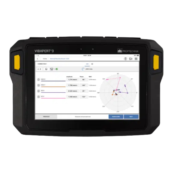
- Page 110 Tap NEXT, then tap MEASURE in the next screen to do the trial run with the attached trial mass. When the values are stable, the STOP button is shown. Tap STOP then switch the machine off. The screen shows the trial run results in digits and as a vector in the polar diagram. The VIBXPERT 3...
- Page 111 On-board help arrow direction shows the path of the balancing run. In the trial run the imbalance should change to reduce the residual imbalance. Tap NEXT to see hint for the trim run. If imbalance reduces, keep the trial weight. If imbalance doubles, remove the trial weight.
-
Page 112: Balancing In Two Planes
The speed point will be measured with a laser trigger sensor. Tap the hamburger menu ( ) to show the measurement screen context menu items, then tap Switch applications (the balancing icon) to show the balancing screen. VIBXPERT 3... - Page 113 On-board help Shows balancing screen. ) to set necessary parameters for balancing procedure. The shown parameters can be set. Note: The item Type is used to select the amplitude parameter that is used in the balancing measure screen. If measured data is available, the data can be entered manually as amplitude and phase values in the bal- ancing measure screen.
- Page 114 Select the locations to measure for the balancing procedure. Note:Before the laser trigger sensor and the vibration sensors are mounted and connected to VIBXPERT 3 make sure that all preparations for the procedure have been correctly done. VIBXPERT 3...
- Page 115 ) and select 2-plane bal- ancing. When 2-plane balancing is selected, the measure locations can then be posi- tioned on the necessary plane. Tap APPLY to confirm selections Mount the sensors as necessary then connect them to the applicable VIBXPERT 3 inputs. Version:1.0...
- Page 116 Shows the distribution of the measure locations used to measure balancing. These are shown in numerical form. Shows the two planes, A and B, used to measure bal- ancing. VIBXPERT 3...
- Page 117 On-board help This button cycles through MEASURE, CANCEL and STOP. MEASURE is used to start the measure procedure; CANCEL is used to stop procedure if necessary; STOP is used to collect data after a stable measure procedure. Note: When measure is completed, the MEASURE button changes to REMEASURE.
- Page 118 Tap NEXT, then tap MEASURE in the updated screen to do the trial run with the attached trial mass. When the values are stable, the STOP button is shown. VIBXPERT 3...
- Page 119 On-board help Tap STOP then switch the machine off. The screen shows the trial run results in digits and as a vector in the polar diagram. The arrow direction shows the path of the balancing run. In the trial run the residual imbal- ance should reduce.
- Page 120 Note:It is possible to apply correction masses on both planes at the same time. It is also possible to change the correction mode from free to fixed at any time in cor- VIBXPERT 3...
- Page 121 On-board help rections. Version:1.0...
-
Page 122: Technical Data - Vibxpert 3
On-board help Technical data – VIBXPERT 3 Parameter Details Measure channels Number 6 synchronous analog channels 2 trigger points Channels 1–6 Frequency range: 0 to 50 kHz Voltage: -20 to +20 V Input impedance: 78 kΩ IEPE Linedrive Connectors 1 and 4: Triaxial sensor, single axis sensor and VIBCODE... - Page 123 On-board help Parameter Details Operation Multi-touch — gesture control Glove-compatible Illumination Backlit, adjustable Ambient light sensor Power supply Battery type Lithium-Ion rechargeable battery Nominal voltage 7.2 V Energy density 72 Wh Charge time (typ- 6.5 hrs (0 to 100% @ 25 °C / 77 °F) ical) 3.5 hrs (0 to 80% @ 25 °C / 77 °F) Charge tem-...
- Page 124 Storage: -20 °C to +60 °C (-4 °F to +140 °F) Humidity 0% to 90 %, non-condensing Certification CE, RoHS, FCC, FCC/IC , UK CA Output Channels (Trigger 1 and Trigger 2) Stroboscope con- TTL output trol Frequency range 0.1 to 1000 Hz VIBXPERT 3...
-
Page 125: Declaration Of Conformity
PRÜFTECHNIK website: www.pruftechnik.com LIMITED WARRANTY AND LIMITATION OF LIABILITY This Fluke product is warranted to be free from defects in material and workmanship under nor- mal use and service for two years from the date of purchase. This warranty does not cover fuses, disposable batteries, or damage from accident, neglect, misuse, alteration, con- tamination, or abnormal conditions of operation or handling.
Need help?
Do you have a question about the VIBXPERT 3 and is the answer not in the manual?
Questions and answers