Fluke Data Acquisition System/Data Logging System 2680A Getting Started Manual
Data acquisition system/data logging system
Hide thumbs
Also See for Data Acquisition System/Data Logging System 2680A:
- Service manual (254 pages) ,
- User manual (274 pages)

Related Manuals for Fluke Data Acquisition System/Data Logging System 2680A


Summary of Contents for Fluke Data Acquisition System/Data Logging System 2680A
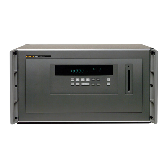
- Page 1 ® 2680A/2686A Data Acquisition System/Data Logging System Getting Started Guide June 2002 © 2002 Fluke Corporation. All rights reserved. Printed in USA All product names are trademarks of their respective companies.
- Page 2 Fluke warrants that software will operate substantially in accordance with its functional specifications for 90 days and that it has been properly recorded on non-defective media. Fluke does not warrant that software will be error free or operate without interruption. The software is neither intended nor warranted for use in medical or any other applications where human safety may be a concern.
-
Page 3: Safety Information
Safety Information This is an IEC safety Class 1 product. Before using, the ground wire in the line cord or rear panel binding post must be connect to an earth ground for safety. Interference Information This equipment generates and uses radio frequency energy and if not installed and used in strict accordance with the manufacturer’s instructions, may cause interference to radio and television reception. -
Page 4: Ac Power Source
SAFETY TERMS IN THIS MANUAL This device has been designed and tested to meet the requirements of EN61010-1 (Safety Requirements for Electrical Equipment for Measurement, Control and Laboratory Use). It is an Installation Category II device intended for operation from a normal single phase supply. -
Page 5: Dc Power Source
The input is protected by a 4 ampere fuse internal to the device. This fuse should only be replaced by a qualified Fluke technician. GROUNDING THE DEVICE... -
Page 6: Do Not Operate In Explosive Atmospheres
DO NOT ATTEMPT TO SERVICE UNLESS YOU ARE A FLUKE QUALIFIED REPAIR TECHNICIAN To avoid personal injury or death, remove the AC power cord and all analog and digital connector modules before servicing the device. -
Page 7: Additional Safety Information
Additional Safety Information The following table provides additional safety information. Specification Size Weight Power Safety Operating Temperature Range Storage Temperature Range Relative Humidity Altitude Warm-up Time General Specifications Characteristic 473 mm (18.6 in) x 423 mm (17 in) x 237 mm (9.3 in) 2680A/2686A (empty) 8.5 Kg (18.9 lb) 2680A –... -
Page 9: Table Of Contents
Interconnection Using 10/100BaseT (Twisted Pair) Ethernet Wiring.. 20 Installing Host Computer Networking Software ... 22 Setting Host Computer Networking Parameters... 23 Introducing Fluke DAQ Software ... 24 Installing Fluke DAQ Software... 24 Understanding the User Interface... 26 Using the Toolbar ... 26 Understanding the Workspace Area ... - Page 10 Trend Dialog... 33 Alarm Dialog... 33 Mail and Web Settings Dialogs... 33 Managing Your Network Using Fluke DAQ ... 34 Inserting and Configuring a 268XA Device... 34 Inserting and Configuring a Module ... 39 Inserting and Configuring a Channel ... 43 Configuring a Computed Channel...
-
Page 11: Getting Started
The systems scan the 20 to 120 analog channels and calculate the values for the 60 computed channels. Interval timers, alarm conditions, and/or an external signal input can trigger scans. The Fluke DAQ software configures and controls up to 99 268XA devices via an Ethernet connection. The software provides the means to view scan data and log it into files. -
Page 12: Contacting Fluke
The CD contains necessary documentation for proper use and operation of the product. If the CD is damaged or if you are unable to access product documentation on the CD, visit the Fluke Web site or contact Fluke at any of the numbers listed above. -
Page 13: Configuring The 268Xa
1 for examples.) BCN Range The BCN can be any number from 01 to 99. If you plan to install Fluke DAQ software for isolated network operation, each device on the network must have a unique BCN. BCN Review or Set identifier The REVIEW annunciator displays when reviewing the BCN;... - Page 14 Getting Started Guide REVIEW Communications display for reviewing the Base Channel Number (BCN) Base Channel Number display for setting the BCN 10s digits (for example, 45) REVIEW Base Channel Number display for reviewing the BCN number (for example, 45) Figure 1. Examples for Reviewing and Setting the BCN Communications display for setting the BCN Front Panel display for an device with BCN 45...
-
Page 15: Reviewing And Setting The Line Frequency
Reviewing and Setting the Line Frequency Perform the procedure below to review or set the line frequency. Line frequency selection allows the device to optimize internal circuitry for best accuracy. (See Figure 2 for examples.) Line Frequency Choices Select 50 Hz or 60 Hz as the frequency of the primary power when an ac source powers the device. - Page 16 Getting Started Guide REVIEW Communications display for reviewing the line frequency Communications display for setting the line frequency Line frequency display for setting the line frequency to 60 Hz Line frequency display for setting the line frequency to 50 Hz REVIEW Line frequency display for reviewing the line frequency (60 Hz) Figure 2.
-
Page 17: Reviewing And Setting The Network Type
(See Figure 3 for examples.) If you use Fluke DAQ software for isolated network operation and set the devices’ network type to isolated, you do not need to know or set IP addresses for your devices. - Page 18 Getting Started Guide REVIEW Communications display for reviewing the network type Communications display for setting the network type Network display for setting the network type to isolated Network display for setting the network type to general REVIEW Network display for reviewing the network type (isolated network) Figure 3.
- Page 19 If you set Fluke DAQ Software for general network operation, you must set the network type of each device to general. You will need to enter an IP address, and possibly a socket port, subnet mask and gateway address into each device. Get this information from your network administrator.
- Page 20 Getting Started Guide REVIEW Communications display for reviewing the network type Communications display for setting the network type Network display for setting the network type to general Socket Port display for setting the first digit (for the example 04369) Socket Port display for setting the second digit (for the example 04369) Figure 4.
- Page 21 IP address display for setting an IP:0 digit (for example, 129:196:152:101) IP address display for setting an IP:1 digit (for example, 129:196:152:101) IP address display for setting an IP:1 digit (for example, 129:196:152:101) IP address display for setting an IP:2 digit (for example, 129:196:152:101) IP address display for setting an IP:3 digit (for example, 129:196:152:101) Figure 4 Examples for Reviewing and Setting General Network Parameters (cont) Configuring the 268XA...
-
Page 22: Reviewing And Setting The General Network Socket Port
Getting Started Guide Reviewing and Setting the General Network Socket Port Perform the procedure below to review or set the general network Socket Port (1024 to 65535). The default is 04369. In order to communicate with each other, a host computer and an device must use the same socket port number. (See Figure 4 for examples.) General Network Socket Port Enter the Socket Port supplied by your network administrator. -
Page 23: Reviewing And Setting The General Network Ip Address
Reviewing and Setting the General Network IP Address Perform the procedure below to review or set the device’s general network Internet Protocol (IP) address. General Network IP Address Enter the IP Address supplied by your network administrator for each BCN. The format is four 3 digit segments: IP0.IP1.IP2.IP3. -
Page 24: Reviewing And Setting The Subnet Mask And Default Gateway
Getting Started Guide Reviewing and Setting the Subnet Mask and Default Gateway If communication between the host computer and the 2680 Series passes through a router or gateway, you must set the subnet mask and default gateway address on both the host computer and the device. Get this information from your network administrator. - Page 25 The network number of the device must match that of the gateway. For example, if the gateway IP address is 129.196.180.93, and the subnet mask is 255.255.255.0, the network number is 129.196.180.0, and the device IP address must be in the range 129.196.180.1 to 129.196.180.254. Table 7.
-
Page 26: Viewing The Device Ethernet Address
Ethernet Address Format The Ethernet address is a 12 digit hexadecimal number. For example, 00:80:40:12:34:56. The first 6 hexadecimal digits represent a manufacturer, for example, 00:80:40 represents Fluke Corporation. The remaining digits are a sequential number assigned during manufacturing. Ethernet addresses are always unique; they are never altered, reused, or duplicated. - Page 27 REVIEW Communications display for viewing the device Ethernet address REVIEW Ethernet address display for viewing byte 0 (for example 00-80-40-12-34-56) REVIEW Ethernet address display for viewing byte 2 (for example 00-80-40-12-34-56) REVIEW Ethernet address display for viewing byte 4 (for the example 00-80-40-12-34-56) REVIEW Ethernet address display for viewing byte 5 (for example 00-80-40-12-34-56) Figure 5.
-
Page 28: Host Computer And Network Preparation
Getting Started Guide Host Computer and Network Preparation This section contains information for preparing your host computer and setting up network communication, as summarized below. Installing Host Computer Ethernet Adapter Skip this section if you have an Ethernet adapter installed on your computer. Since the installation procedures for Ethernet adapters change frequently and without notice, you must follow the instructions supplied with your particular Ethernet adapter. - Page 29 Install Ethernet Ethernet Card Adapter Interconnect Host Computers Instruments Instrument Install Networking Software Install Fluke DAQ Software Figure 6. Preparing for Network Operation Host Computer and Network Preparation Card Windows 98/NT or higher Fluke DAQ for Windows alg02f.eps...
-
Page 30: Device And Host Computer Interconnection
Getting Started Guide Device and Host Computer Interconnection You may interconnect 268X devices and host computer(s) with 10/100 BaseT (twisted pair) wiring. If your site is already wired, you can use the wire in place. If your site is not wired, you are connecting your device directly to your host computer. - Page 31 Direct connection between a single host computer and a single device with 10/100BaseT is possible, but you must use a special cable that has its transmit and receive lines crossed. The typical general network configuration uses 10BaseT Twisted Pair Ethernet for interconnection (shown).
-
Page 32: Installing Host Computer Networking Software
Getting Started Guide Installing Host Computer Networking Software To establish Ethernet communication in your host computer, you must do the following: Install a driver for the adapter Install TCP/IP protocol stack Set host computer networking parameters This section discusses installing the adapter driver and the TCP/IP protocol stack. You should install the networking software that is most appropriate for your operating system. -
Page 33: Setting Host Computer Networking Parameters
IP address, subnet mask, and possibly its default gateway IP address. Obtain this information from your network administrator. If you plan to use Fluke DAQ software for isolated network operation you must set the host computer’s IP address to 198.178.246.1xx, and its subnet mask to 255.255.255.0. -
Page 34: Introducing Fluke Daq Software
Getting Started Guide ntroducing Fluke DAQ Software Fluke DAQ software provides a graphical user interface (GUI) to the 264XA and 268XA family of data acquisition products. You can use Fluke DAQ software to easily perform the following: Fluke DAQ supports the NetDAQ devices (2640A and 2645A) as well as the 2680A and 2686A. - Page 35 You will need to reboot your computer after you install the Fluke DAQ software. During installation, the following directories and files are installed on you PC. The Fluke DAQ subdirectories contain the following information Alarm Collected alarm data and format information.
-
Page 36: Understanding The User Interface
Using the Toolbar A toolbar appears on all of the Fluke DAQ dialogs. Use the toolbar buttons to add and configure devices 268XA devices and to navigate through the Fluke DAQ application. Each button on the toolbar has a tool tip that identifies the button function. - Page 37 Ack command (Last Alarm or All Alarms) in the Alarms dialog. Web and Alarm Mail Settings button. Used to enter Fluke DAQ web configuration information and to configure Fluke DAQ to send e-mail messages reporting alarm condition.
-
Page 38: Understanding The Workspace Area
Getting Started Guide Understanding the Workspace Area The Workspace Area consists of a network TreeView and a set of buttons. Use the Workspace Area to: Open, Save, and Remove configuration files. You can also use the Save As button to rename an existing configuration file. Insert and Remove devices, modules and channels Navigate through the configuration setup dialogs Open an existing... -
Page 39: Checking Operational Status
Checking Operational Status The icons in the TreeView change to indicate the device status. Below are all the possible icons and their meaning: Device Status Icon Yellow or blue device icons indicates the device is not connected. Green device icon indicates the device is connected and communicating. Red device icon indicates an device error. -
Page 40: Configuration Dialogs
Network Configuration dialog appears when you click on the root node in the TreeView. Device Configuration Dialog You can configure your 268XA devices using the Fluke DAQ Configuration dialog. This dialog appears when you select a 268XA device in the TreeView. You can use the Configuration dialogs to:... -
Page 41: Module Configuration Dialog
The Save command saves the actual 2686A configuration to the PC Card. The Load command loads the configuration from the PC Card to the 2686A. Set up the device general settings Specify which module will control the trigger out signal for master/slave operation Module Configuration Dialog A 268XA device can have up to 6 modules with specific configuration settings. -
Page 42: Communication Dialogs
View alarm conditions of computed channels Security Dialogs You can use the system security features to protect device configuration information. The system security feature allows the administrator to add and remove Fluke DAQ users, allow other users to configure devices, and to change user passwords... -
Page 43: Trend Dialog
Mail and Web Settings Dialogs You can use the Web and Alarm Mail Settings dialog to enter Fluke DAQ web configuration information and to configure Fluke DAQ to send e-mail messages reporting alarm condition. -
Page 44: Managing Your Network Using Fluke Daq
Getting Started Guide Managing Your Network Using Fluke DAQ The following procedures provide detailed instructions for using Fluke DAQ to: Insert and configure 268XA devices, modules, channels, and computed channels. Start a scan View scan data. View alarms. Inserting and Configuring a 268XA Device To insert and configure a device 1. - Page 45 Isolated if the PC is connected directly to the 268XA device or General if the 268XA is part of a network. Port Number 4369 is the default port number. Fluke recommends that you use the default port number. Group is externally wired All devices may be wired together in a master/slave arrangement.
- Page 46 Device Type. The Base Channel number auto-increments when you add devices. Fluke DAQ also supports 2640A and 2645A NetDAQ devices. Some of the Fluke DAQ configuration dialogs may differ from those for the 268XA. 5. In the TreeView panel, select the device you just added.
- Page 47 Getting Started Managing Your Network Using Fluke DAQ 6. Set the IP Address on the Device Settings dialog. Other fields are optional. You may need to contact your Internet support staff to determine the IP Address. alg106s.bmp The dialog box entries include: IP Address Enter the IP Address of the device you are adding.
- Page 48 Getting Started Guide Monitor Channel Select a channel measurement to display on the device front panel. You can also choose to increment though active channels or to automatically scan through all active channels. Default is None. Scan Parameters Parameters you can set to start, stop, and save scan data. You can also select Start Scan on Power Up for stand-alone operation or to automatically start scanning after a power loss.
-
Page 49: Inserting And Configuring A Module
You can attach up to 6 modules to the device. You can only have a Digital I/O in Module Slot 6 and can have only one per device. Module Type Valid module types are Analog PAI, Analog FAI, or Digital DIO. Managing Your Network Using Fluke DAQ alg107s.bmp alg108s.bmp... - Page 50 Getting Started Guide 3. Click OK. The modules are added to the device and appear in the TreeView panel. 4. Select one of the analog modules you inserted and the Analog Module settings dialog appears. alg109s.bmp alg110s.bmp...
- Page 51 Getting Started Managing Your Network Using Fluke DAQ The dialog box entries include: Interval Trigger Uses the interval timer (interval 1 timer) to set the scan rate for normal operation in a module. The interval is user settable. External Trigger Uses the Trigger input signal to start a scan.
- Page 52 Getting Started Guide If you are configuring a DIO module, the Totalizer Configuration dialog appears. The dialog box entries include: Start Count Used to specify a start count. Debounce Select debounce to ignore signals with a period less than 2 ms (500 Hz); otherwise, signals up to 5 kHz can be counted.
-
Page 53: Inserting And Configuring A Channel
2. Specify the number of channels you want to insert on the Insert Channel dialog box. 3. Click OK. The channels are added to the module and appear in the TreeView panel. Managing Your Network Using Fluke DAQ alg112s.bmp alg113s.bmp alg114s.bmp... - Page 54 Getting Started Guide 4. Select a channel and the Module settings dialog appears. The dialog box entries include: CH # XX-YYY. The first two digits identify the chassis (01-99). The next digit identifies the module (1-6), and the last two digits identify the channel (1-20). Label Use the label field to identify where the channel is used in your application.
-
Page 55: Configuring A Computed Channel
Input or Scaled Range Use the M and B values to calculate the Input and Scaled range or you can enter the Input and Scaled range and Fluke DAQ will calculate the M and B values for you. Configuring a Computed Channel Computed channels provide a means to calculate values based on measurements. - Page 56 Getting Started Guide 2. Specify the number of channels you want to insert on the Insert Channel dialog box. 3. Click OK. The computed channels are added and appear in the TreeView panel. alg117s.bmp alg118s.bmp...
- Page 57 Getting Started Managing Your Network Using Fluke DAQ 4. Select a computed channel and the Computed Channel settings dialog appears. alg119s.bmp The dialog box entries include: CH # Computed channels are assigned channel numbers from 901 to 960. Label Use the label field to identify where the computed channel is used.
- Page 58 Input or Scaled Range Use the M and B values to calculate the Input and Scaled range or you can enter the Input and Scaled range and Fluke DAQ will calculate the M and B values for you. Note...
-
Page 59: Using Equations With Computed Channels
= c101*c102**2*ts/1000 This equation assumes that the resistance and current are constant for the duration of the time interval. It also does not calculate the energy used in the first increment of time. Managing Your Network Using Fluke DAQ Note Note... - Page 60 Getting Started Guide The following is a list of the valid notations. Axxx Alarm on/off (Boolean value of 1 or 0) Cxxx Any channel measurement C9xx Computed channel TS Time since last measurement (milli seconds) TOT Totalizer Operators +, -, *, /, **, unary +, unary -, abs, exp, int, ln, log, and sqr. alg120s.bmp...
-
Page 61: Starting A Scan
You must have channels configured for operation before starting a scan. Starting a Configuration Scan To start a configuration scan 1. Click the on the Fluke DAQ toolbar and highlight the configuration in the TreeView panel. 2. Click to start the scan. Click Managing Your Network Using Fluke DAQ Note to stop the scan. -
Page 62: Starting A Device Scan
Getting Started Guide Starting a Device Scan To start a device scan 1. Click the TreeView panel. 2. Click to start the scan. Click on the Fluke DAQ toolbar and highlight a device in the to stop the scan. alg122s.bmp... -
Page 63: Starting A Scan Using Spy
To start a Spy scan 1. Click the on the Fluke DAQ toolbar. The Spy icon appears in the lowest item in the TreeView panel. 2. Click the Spy icon and the Spy window appears. You may select up to 8 channels, including DIO and totalizer. -
Page 64: Viewing Module Measurement Data
NC indicates that a channel is not configured. To view module measurement data 1. Click the 2. Highlight a module in the TreeView panel and the module measurement data appears. on the Fluke DAQ toolbar. alg124s.bmp... -
Page 65: Using The Digital I/O Points Communication Dialog
Getting Started Managing Your Network Using Fluke DAQ Using the Digital I/O Points Communication Dialog You can use the Digital I/O Points Communication dialog to set any of the 8 relays or 20 DIO pins active when an alarm condition occurs in the channel. You can also view status of all of the relays and DIO pins and set or clear IO bits and relays. -
Page 66: Using Trend To View Collected Data
???????. Channels that are still scanning will continue to show the latest data. To use the trend feature 1. Click the appears. If a device is stopped, the data for all button on the Fluke DAQ toolbar and the Trend dialog alg126.bmp... - Page 67 Getting Started Managing Your Network Using Fluke DAQ The dialog box entries include: Click to select the device, module, or channel that you want to view in the chart. You can view up to 8 items on the chart. Type Specify On Line or History scan view.
- Page 68 Getting Started Guide Device ID Any device from 1 to 99. Module A specific module in a device or you can select all of the modules. Start Date/Start Time Start Date and Start Time are used to select the data. Data is stored with the date the scan began.
-
Page 69: Changing The Chart Display
Getting Started Managing Your Network Using Fluke DAQ Changing the Chart Display To change the strip chart display The Trend Setting dialog appears when you double-click on the chart screen. Use the Trend Settings dialog to change the location of the upper and lower boundary points, the scaling seen on the chart, and the color of the plot pens you are using. -
Page 70: Viewing Alarms
When a channel has two alarms, only one alarm can be active at a time. If one alarm becomes active and then a second alarm becomes active, Fluke DAQ will acknowledge the first alarm and show the second alarm as active. - Page 71 Getting Started Managing Your Network Using Fluke DAQ The dialog box entries for On Line include: Type Specify On Line or History alarm view. Click the appropriate button to acknowledge the Last Alarm or All Alarms. Alarm Device Filters Choose to view alarms from a select set of devices, modules, and channel.
-
Page 72: Using Fluke Daq System Security Features
You can use the system security features to protect device configuration information. The system security feature allows the administrator to add and remove Fluke DAQ users, allow other users to configure devices, and to change user passwords. Only the administrator (Root user) can use the security system configuration function. -
Page 73: Configuring Web And Alarm Mail Settings
Configuring Web and Alarm Mail Settings You can use the Web and Alarm Mail Settings dialog to enter Fluke DAQ web configuration information and to configure Fluke DAQ to send e-mail messages reporting alarm condition. The Web Settings portion of dialog is used to specify a URL where scanned values from your 268XA device will be sent. - Page 74 Data Server IP Address The IP address of the computer running the Fluke DAQ application. Fluke DAQ fills in this field with the first IP address found on the computer. You must change this setting if you want to use a different interface or if you are using a Dynamic Host Configuration Protocol (DHCP) on your server.
Need help?
Do you have a question about the Data Acquisition System/Data Logging System 2680A and is the answer not in the manual?
Questions and answers