Sign In
Upload
Manuals
Brands
Fluke Manuals
Data Loggers
2686A
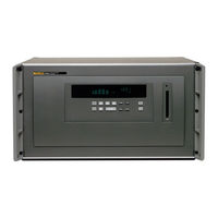
User Manuals: Fluke 2686A Data Logging System
Manuals and User Guides for Fluke 2686A Data Logging System. We have
3
Fluke 2686A Data Logging System manuals available for free PDF download: User Manual, Service Manual, Getting Started Manual
Fluke 2686A Service Manual (254 pages)
Data Acquisition System/Data Logging System
Brand:
Fluke
| Category:
Data Loggers
| Size: 6 MB
Table of Contents
Table of Contents
7
List of Tables
13
List of Figures
15
Introduction and Specifications
19
Introduction
19
Block Diagrams
21
268XA Chassis
21
Specifications
23
2680A/2686A Combined Specifications
23
2680A/2686A General Specifications
24
Real-Time Clock and Calendar
25
Trigger in Specifications
25
Trigger out Specifications
25
Master Alarm Output Specification
26
Communication I/O
26
2686A PC Card Storage
26
Precision Analog Input (PAI) A/D Specifications
27
Specifications PAI A/D DC Voltage Measurement
27
PAI A/D AC Voltage Measurement Specifications
29
PAI A/D 4-Wire Resistance Measurement Specifications
31
PAI A/D 2-Wire Resistance Measurement Specifications
32
PAI A/D 4-Wire RTD Per ITS-1990 Measurement Specifications
32
PAI A/D 2-Wire RTD Per ITS-1990 Measurement Specifications
32
PAI A/D Thermocouple Per ITS-1990 Measurement Specifications
33
PAI A/D Frequency Measurement Specifications
36
Fast Analog Input (FAI) A/D Specifications
37
FAI A/D DC Voltage Measurement Specifications
37
FAI A/D AC Voltage Measurement Specifications
38
FAI A/D 4-Wire Resistance Measurement Specifications
40
FAI A/D 2-Wire Resistance Measurement Specifications
41
FAI A/D 4-Wire RTD Per ITS-1990 Measurement Specifications
41
FAI A/D Thermocouple Per ITS-1990 Measurement Specifications
42
FAI A/D Frequency Measurement Specifications
44
Digital Input/Output Module
45
Digital Input/Output Specifications
45
Totalizer Input Specifications
46
Digital Relay Specifications
46
Options and Accessories
47
Theory of Operation
49
Introduction
51
Communication Control System
51
268XA Main Supply Circuit
52
Chapter 2
53
Main Power Supply
53
Secondary Supplies
53
Out-Guard Overview
53
Microprocessor
54
System Interface Unit
54
Fpga
55
Other Bus Devices
56
FPGA Block Diagram
56
Serial Devices
57
Trigger In/Out, Master Alarm
57
PCMCIA Interface PCA (2686A-4041)
58
Backplane PCA (268XA-4001)
58
Display Interface
59
Module Interface
59
Module Power Supply PCA (268XA-4031)
59
Digital Input/Output PCA
59
Microcontroller
60
Data Input Threshold
60
Digital Input Buffers
61
Digital Output Drivers
61
Relay Output Drivers
61
Totalizer Input
62
Totalizer Enable
62
A/D Theory of Operations
62
A/D Converter PCA Block Description
62
Analog Measurement Processor
63
Input Protection
63
Input Signal Conditioning
63
Analog-To-Digital (A/D) Converter
63
Inguard Microcontroller
63
Channel Selection
63
Open Thermocouple Check
64
Analog Input PCA Block Description
64
20-Channel Terminals
64
Reference Junction Temperature
64
A/D Converter PCA Circuit Description
64
A3 A/D Converter Block Diagram
65
Function Relays
66
Input Protection
66
Input Signal Conditioning
66
Stallion Chip
66
Channel Selection Circuitry
67
DC Volts and Thermocouples Measurement Circuitry
67
DC Volts 300 V Range Simplified Schematic
68
Ohms and RTD Measurement Circuitry
68
RTD Measurement Simplified Schematic
69
AC Volts Measurement Circuitry
70
AC Volts #V Range Simplified Schematic
71
Frequency Measurements
71
Active Filter (ACV Filter)
72
Analog/Digital Converter Circuit
72
Autozero
72
Voltage Reference Circuit
72
Deintegrate1
73
Integrate
73
Integrator Output Wavefrom for Input Near + Full Scale
74
Deintegrate2
75
Inguard Digital Kernel Circuitry
75
Integrator Output Waveform for Input Near - Full Scale
75
Overhead
75
Open Thermocouple Detect Circuitry
76
A4 Analog Input PCA Circuit Description
76
A31 A/D Power Supply Circuit Description
77
Controller/System Power (Outguard) to A3 A/D Converter (Inguard) Communications
77
Special Codes
77
Resets
77
Commands
78
Perform Scan
78
Perform Self-Test
79
Return Firmware Version
79
Return Boot Firmware Version
79
Set Global Configuration
80
Set Channel Configuration
80
Do Housekeeping
80
Checksums
81
Errors
81
Power-Up Protocol
81
Inguard Unresponsive
81
Inguard Software Description
81
Hardware Elements
82
Channel MUX
82
Function Relays
83
Stallion Chip and Signal Conditioning
84
A/D
87
DISCHARGE Signal
90
Open-Thermocouple Detector
90
Channel Measurements
90
Reading Rates
90
Measurement Types
91
Autoranging
93
Overload
93
Housekeeping Readings
93
Reading Types
93
Housekeeping Schedule
94
Self-Tests
95
Power-Up Self-Tests
95
Self-Test Command
95
Maintenance
97
Chapter 3
99
Introduction
99
Self-Test Diagnostics and Error Codes
99
Cleaning
102
AC Fuse Replacement
103
Replacing the Fuse
103
DC Fuse Replacement
104
DC Fuse Location
105
Performance Verification
107
Introduction
109
Chapter 4
109
Configuring the Performance Test Setup
109
Initializing the Performance Test Setup
111
Connection between Device and Host
111
Accuracy Performance Tests
112
Master Alarm Output Tests
113
RS-232 Master Alarm Output Test
113
Fluke DAQ Master Alarm Output Test
113
Trigger Input Tests
113
RS-232 Trigger Input Test
113
Fluke DAQ Trigger Input Test
114
Trigger Output Tests
114
RS-232 Trigger Output Test
114
Fluke DAQ Trigger Output Test
114
Volts DC Accuracy Test (PAI Module)
115
Volts DC Accuracy Test (FAI Module)
116
Volts AC Accuracy Test
117
Frequency Accuracy Test
117
Analog Channel Integrity Test
118
Open Thermocouple Response Test
118
2-Wire Resistance Accuracy Test (PAI) - Optional
119
2-Wire Resistance Accuracy Test (FAI Module) - Optional
120
4-Wire Resistance Accuracy Test (PAI Module)
122
4-Wire Resistance Accuracy Test (FAI Module)
125
Digital Input/Output Tests
126
RS-232 Digital Input/Output Test
126
DIO Connector Module
126
Fluke DAQ Digital Input/Output Test
127
DIO Relay/Fuse Tests
127
RS-232 DIO Relay Fuse Test
127
Fluke DAQ DIO Relay Fuse Test
127
Totalizer Tests
128
RS-232 Totalizer Count Test
128
RS-232 Totalizer Count and Enable Test
128
RS-232 Totalizer Count and Direction Test
128
RS-232 Totalizer Count and Debounce Test
129
Fluke DAQ Totalizer Count Test
129
Fluke DAQ Totalizer Count and Enable Test
129
Fluke DAQ Totalizer Count and Direction Test
130
Fluke DAQ Totalizer Count and Debounce Test
130
Calibration
131
Chapter 5
133
Introduction
133
Calibration
133
Methods of Calibration
133
Preparing for Calibration
133
Device and Host Computer Calibration Setup
135
Universal Input Module Calibration Connections
135
Ending Calibration
136
RS-232 Device Configuration Parameters
136
Two-Wire Calibration Connection
136
Manual Calibration Procedure
137
Four-Wire Calibration Connection
137
Manual Calibration Commands
139
DC Calibration Procedure
140
AC Calibration Procedure
142
Resistance Calibration Procedure
143
Frequency Calibration Procedure
145
Diagnostic Testing and Troubleshooting
147
Chapter 6
149
Introduction
149
Servicing Surface-Mount Assemblies
149
Error Detection
150
FLASH ROM Parameter Defaults
153
Background Testing
153
Retrieving Error Codes Using RS-232
154
Selecting the Diagnostic Tools
154
Diagnostic Tool Dio
154
Diagnostic Tool Relay
155
Diagnostic Tool Ids
155
Diagnostic Tool Conf
156
Diagnostic Display Test
157
COMM Parameter Reset
157
Using the RS-232 Interface
157
Command Processing
157
Device Configuration
158
Command Set
159
Troubleshooting the Device
171
General Troubleshooting
171
Sys/Ctrl PCA Troubleshooting
182
Troubleshooting the Sys/Ctrl PCA Digital Kernel
182
Troubleshooting the RS-232 Interface
182
Troubleshooting the Ethernet Interface
183
Troubleshooting the Keypad, Master Alarm Output, Trigger Input, and Trigger out Lines
183
Troubleshooting the Power Supply
183
A2 Display PCA Troubleshooting
183
Display Test Pattern #1
184
Display Test Pattern #2
184
Variations in the Display
185
PCMCIA PCA Troubleshooting
186
A/D Power Supply PCA Troubleshooting
186
DIO Module Troubleshooting
186
Digital Input Buffers
187
Digital Output Drivers
187
Relay Output Drivers
187
Totalizer Input
188
Totalizer Enable
188
Digital Output PCA Troubleshooting
188
A3 A/D Converter Module Troubleshooting
188
A3 Kernel
188
Break/Reset Circuit
189
Out of Tolerance Readings
189
Troubleshooting Relay Problems
190
A4 Analog Input PCA Troubleshooting
190
Troubleshooting Calibration Failures
190
Retrieving Calibration Constants
191
Flukedaq Software
193
Replaceable Parts
195
Introduction
197
How to Obtain Parts
197
Service Centers
197
Parts Lists
198
268XA Final Assembly
204
Blank Module
205
DIO Module
206
FAI Module
208
PAI Module
210
Isothermal Input
212
Figure Title Page
213
Schematics
213
Backplane PCA
215
Controller/System Power PCA
217
Digital I/O PCA
223
Backplane Extender PCA
227
Extender PCA
229
A/D Supply Assembly
231
Pcmcia Pca
233
Output PCA
235
Analog Input Connector PCA
251
Display PCA
253
Advertisement
Fluke 2686A User Manual (274 pages)
Data Acquisition System/Data Logging System
Brand:
Fluke
| Category:
Data Loggers
| Size: 3 MB
Table of Contents
Table of Contents
9
Overview
19
Introduction
21
Contacting Fluke
21
Instrument Features and Capabilities
23
Mainframe Features
26
Chapter 1
26
Trigger Input
26
Trigger Output
26
PC Card ATA Interface (2686A Only)
26
Master Alarm
27
Interval Trigger
27
External Trigger
27
Alarms
27
Channel Monitoring
28
Alarm Trigger
28
Channel Numbering
28
Computed Channels
29
MX+B Scaling
29
Analog Channels
29
Digital I/O Module Option
30
Digital I/O
30
Relay Output
30
Totalizer
30
User Interface
31
Operating a 2680 Series Data Acquisition System
32
Isolated Networks
32
General Networks
32
Ethernet Port
32
Group Operations
33
Scanning and Logging
33
RS-232 Interface
35
Host Computer Requirements
35
Options and Accessories
36
Preparing for Operation
37
Introduction
39
Instrument Preparation
40
Chapter 2
41
Unpacking and Inspecting the Instrument
41
Positioning and Rack Mounting
41
Connecting to a Power Source and Grounding
41
Operating Using AC Power
42
Operating Using DC Power
43
Grounding and Common Mode Voltage
43
Alarm/Trigger I/O Connection
43
Trigger Input
44
Trigger Output
45
Master Alarm
46
External Trigger Wiring for a Group
46
Universal Input Module Analog Connections (2620A-180)
48
Shielded Wiring
51
Crosstalk Considerations
51
Digital I/O Connector Module
51
Digital I/O
52
Totalizer
52
Totalizer Enable
53
Relays
53
Controls and Indicators
53
Front Panel Controls
53
Front Panel Indicators
55
Rear Panel Controls
58
Rear Panel Indicators
59
Front Panel Operating Procedures
60
Power-On Options
60
Displaying a Monitor Channel
61
Displaying the Digital I/O Status
63
Displaying Relay Status
64
Displaying the Totalizer Status
66
Reviewing and Setting the Base Channel Number
67
Reviewing and Setting the Line Frequency
69
Reviewing and Setting the Network Type
71
Reviewing and Setting the General Network Socket Port
76
Reviewing and Setting the General Network IP Address
77
Reviewing and Setting the Subnet Mask and Default Gateway
78
Viewing the Instrument Ethernet Address
80
Reviewing and Setting PC Card Options
82
Host Computer and Network Preparation
83
Installing Host Computer Ethernet Adapter
83
Instrument and Host Computer Interconnection
85
Host Computer/Instrument Direct Connection
85
Interconnection Using 10/100Baset (Twisted Pair) Ethernet Wiring
86
Set up Windows Networking
88
Setting Host Computer Networking Parameters
89
Installing Fluke DAQ Software
89
Testing and Troubleshooting
90
Installing and Testing the Installation
90
Troubleshooting Network Problems
94
Using Fluke DAQ Software
99
Chapter 3
101
Introduction
101
Installing Fluke DAQ Software
102
Understanding the User Interface
103
Fluke DAQ Main Window
103
Using the Toolbar
104
Understanding the Workspace Area
106
Configuration Dialogs
107
Main Configuration Dialog
107
Instrument Configuration Dialog
107
Module Configuration Dialog
108
Analog Channel Configuration Dialog
108
DIO Configuration Dialog
108
Computed Channel Configuration Dialog
108
Communication Dialogs
109
Main Communication Dialog
109
Instrument Communication and Status Dialog
109
Module Communication Dialog
109
Digital I/O Points Dialog
109
Computed Channels Dialog
109
Communications Icons
110
Security Dialogs
110
Trend Dialog
111
Alarm Dialog
111
Mail and Web Settings Dialogs
111
Managing Your Network Using Fluke DAQ
112
Inserting and Configuring an Instrument
112
Inserting and Configuring a Module
117
Inserting and Configuring a Channel
121
Configuring a Computed Channel
124
Configuring Multiple Channels
127
Using Equations with Computed Channels
128
Starting a Scan
130
Starting a Configuration Scan
130
Starting an Instrument Scan
131
Getting Scan Data
131
Viewing and Resetting the Totalizer
132
PC Card Functions
132
Getting PC Card Information
132
Formatting the PC Card
132
Getting PC Card Scan Data
133
Starting Spy
134
Viewing Module Measurement Data
136
Using the Digital I/O Points Communication Dialog
137
Using Trend to View Collected Data
138
Changing the Trend Chart Display
141
Viewing Alarms
142
Configuring Data Files
144
Selecting a Master for a Data Group
145
Advanced Data File Configuration
145
Real-Time Data File Creation
151
Main Window Advanced Settings
153
Using Fluke DAQ System Security Features
154
Configuring Web and Alarm Mail Settings
156
Maintenance
159
Chapter 4
161
Introduction
161
Self-Test Diagnostics and Error Codes
161
Cleaning
164
AC Fuse Replacement
165
DC Fuse Replacement
167
Performance Test
167
Configuring the Performance Test Setup
167
Initializing the Performance Test Setup
169
Accuracy Performance Tests
171
Master Alarm Output Tests
172
RS-232 Master Alarm Output Test
172
Fluke DAQ Master Alarm Output Test
172
Trigger Input Tests
173
RS-232 Trigger Input Test
173
Fluke DAQ Trigger Input Test
173
Trigger Output Tests
173
RS-232 Trigger Output Test
173
Fluke DAQ Trigger Output Test
174
Volts DC Accuracy Test (PAI Module)
174
Volts DC Accuracy Test (FAI Module)
175
Volts AC Accuracy Test
176
Frequency Accuracy Test
177
Analog Channel Integrity Test
178
Open Thermocouple Response Test
178
2-Wire Resistance Accuracy Test (PAI) - Optional
179
2-Wire Resistance Accuracy Test (FAI Module) - Optional
180
4-Wire Resistance Accuracy Test (PAI Module)
182
4-Wire Resistance Accuracy Test (FAI Module)
186
Digital Input/Output Tests
187
RS-232 Digital Input/Output Test
187
Fluke DAQ Digital Input/Output Test
188
DIO Relay/Fuse Tests
188
RS-232 DIO Relay Fuse Test
188
Fluke DAQ DIO Relay Fuse Test
188
Totalizer Tests
189
RS-232 Totalizer Count Test
189
RS-232 Totalizer Count and Enable Test
189
RS-232 Totalizer Count and Direction Test
190
RS-232 Totalizer Count and Debounce Test
190
Fluke DAQ Totalizer Count Test
191
Fluke DAQ Totalizer Count and Enable Test
191
Fluke DAQ Totalizer Count and Direction Test
192
Fluke DAQ Totalizer Count and Debounce Test
192
Calibration
193
Variations in the Display
193
Service
194
Replacement Parts
194
Appendices
195
A Specifications
197
Specifications
197
B Noise, Shielding, and Crosstalk Considerations
229
Noise, Shielding, and Crosstalk Considerations
229
C True-RMS Measurements
233
True-RMS Measurements
233
RTD Linearization
235
D RTD Linearization
237
E Computed Channel Equations
243
Computed Channel Equations
243
Data File Format
245
G Ethernet Cabling
247
Ethernet Cabling
247
H Network Considerations
249
Network Considerations
249
Error Codes
265
Fluke 2686A Getting Started Manual (74 pages)
Data Acquisition System/Data Logging System
Brand:
Fluke
| Category:
Data Loggers
| Size: 9 MB
Table of Contents
Safety Information
3
Interference Information
3
Ac Power Source
4
DC Power Source
5
Grounding the Device
5
Use the Proper Power Cord
5
Do Not Operate in Explosive Atmospheres
6
Additional Safety Information
7
Table of Contents
9
Getting Started
11
Introduction
11
Contacting Fluke
12
Additional Information
12
Configuring the 268XA
13
Reviewing and Setting the Base Channel Number
13
Reviewing and Setting the Line Frequency
15
Reviewing and Setting the Network Type
17
Reviewing and Setting the General Network Socket Port
22
Reviewing and Setting the General Network IP Address
23
Reviewing and Setting the Subnet Mask and Default Gateway
24
Viewing the Device Ethernet Address
26
Host Computer and Network Preparation
28
Installing Host Computer Ethernet Adapter
28
Device and Host Computer Interconnection
30
Host Computer/Device Direct Connection
30
Interconnection Using 10/100Baset (Twisted Pair) Ethernet Wiring
30
Installing Host Computer Networking Software
32
Setting Host Computer Networking Parameters
33
Introducing Fluke DAQ Software
34
Installing Fluke DAQ Software
34
Understanding the User Interface
36
Using the Toolbar
36
Understanding the Workspace Area
38
Checking Operational Status
39
Device Status Icon
39
Module Status Icon
39
Computed Channel Status Icon
39
I/O Module 6
39
Configuration Dialogs
40
Network Configuration Dialog
40
Device Configuration Dialog
40
Module Configuration Dialog
41
Analog Channel Configuration Dialog
41
DIO Configuration Dialog
41
Computed Channel Configuration Dialog
41
Communication Dialogs
42
Device Communication and Status Dialog
42
Module Communication Dialog
42
Digital I/O Points Dialog
42
Computed Channels Dialog
42
Security Dialogs
42
Trend Dialog
43
Alarm Dialog
43
Mail and Web Settings Dialogs
43
Managing Your Network Using Fluke DAQ
44
Inserting and Configuring a 268XA Device
44
Inserting and Configuring a Module
49
Inserting and Configuring a Channel
53
Configuring a Computed Channel
55
Using Equations with Computed Channels
59
Starting a Scan
61
Starting a Configuration Scan
61
Starting a Device Scan
62
Starting a Scan Using Spy
63
Viewing Module Measurement Data
64
Using the Digital I/O Points Communication Dialog
65
Using Trend to View Collected Data
66
Changing the Chart Display
69
Viewing Alarms
70
Using Fluke DAQ System Security Features
72
Configuring Web and Alarm Mail Settings
73
Advertisement
Advertisement
Related Products
Fluke 2680A
Fluke 268XA
Fluke 2635A/C
Fluke 2620A
Fluke 2638A
Fluke 26
Fluke 2635A
Fluke 26500090
Fluke 26500000
Fluke 26500610
Fluke Categories
Measuring Instruments
Test Equipment
Multimeter
Thermometer
Laboratory Equipment
More Fluke Manuals
Login
Sign In
OR
Sign in with Facebook
Sign in with Google
Upload manual
Upload from disk
Upload from URL