Table of Contents
Advertisement
Quick Links
Advertisement
Table of Contents

Subscribe to Our Youtube Channel
Related Manuals for Fluke 1743-BASIC


Summary of Contents for Fluke 1743-BASIC
- Page 1 Power Quality Logger Users Manual PN 2560353 April 2006 Rev.1, 6/06 MyFlukeStore © 2006 Fluke Corporation, All rights reserved. Printed in USA 1.877.766.5412 www. .com All product names are trademarks of their respective companies. Shop for Fluke products online at:...
- Page 2 Fluke's warranty obligation is limited, at Fluke's option, to refund of the purchase price, free of charge repair, or replacement of a defective product which is returned to a Fluke authorized service center within the warranty period.
- Page 3 à offrir une garantie plus étendue ou différente au nom de Fluke. Le support de garantie est offert uniquement si le produit a été acquis par l’intermédiaire d’un point de vente agréé par Fluke ou bien si l’acheteur a payé...
- Page 4 Vertriebsstelle erworben oder der jeweils geltende internationale Preis gezahlt wurde. Fluke behält sich das Recht vor, dem Käufer Einfuhrgebühren für Ersatzteile in Rechnung zu stellen, falls der Käufer das Produkt nicht in dem Land zur Reparatur einsendet, in dem er das Produkt ursprünglich erworben hat.
- Page 5 Fluke autorizzato. Sono esclusi i fusibili, le pile monouso e i prodotti che, a parere della Fluke, siano stati adoperati in modo improprio, alterati, trascurati, contaminati o danneggiati in seguito a incidente o condizioni anomale d’uso e maneggiamento.
- Page 6 A obrigação da Fluke no tocante a esta garantia é limitada, a critério da Fluke, à devolução da importância correspondente ao preço pago pelo produto, a consertos gratuitos, ou à...
- Page 7 Fluke. El soporte técnico en garantía está disponible sólo si el producto se compró a través de un centro de distribución autorizado por Fluke o si el compra- dor pagó el precio internacional correspondiente. Cuando un producto comprado en un país sea enviado a otro país para su reparación, Fluke se reserva el derecho de facturar al Comprador los...
- Page 8 预付运输费;买方将收到修理和返程运输费用(寄发地交货)的帐单。 本担保为买方唯一能获得的全部补偿内容,并且取代所有其它明示或隐含的担 保,包括但不限于适销性或满足特殊目的任何隐含担保。FLUKE 对任何特殊、 间接、偶发或后续的损坏或损失概不负责,包括由于任何原因或推理引起的数据 丢失。 由于某些国家或州不允许对隐含担保的期限加以限制、或者排除和限制意外或后 续损坏,本担保的限制和排除责任条款可能并不对每一个买方都适用。如果本担 保的某些条款被法院或其它具有适当管辖权的裁决机构判定为无效或不可执行, 则此类判决将不影响任何其它条款的有效性或可执行性。 Fluke Corporation Fluke Europe B.V. P.O. Box 9090 P.O. Box 1186 Everett, WA 98206-9090 5602 BD Eindhoven U.S.A. The Netherlands MyFlukeStore 1.877.766.5412 www. .com Shop for Fluke products online at:...
-
Page 9: Table Of Contents
Two Current Transformers............24 Logging..................... 25 Completing the Logging Job............26 Evaluating the Logged Data.............. 27 Methods of Logging................27 Measuring Ranges................27 Signal Sampling................28 Resolution Accuracy................. 28 Voltage Variations ................29 MyFlukeStore 1.877.766.5412 www. .com Shop for Fluke products online at:... - Page 10 Application ................... 54 Logging Function A – “All” parameters........... 55 Logging Values ................55 Applications ................. 56 PQ Log PC Application Software ............57 Online Test ................... 58 ASCII Export................59 MyFlukeStore 1.877.766.5412 www. .com Shop for Fluke products online at:...
- Page 11 (continued) Contents Timeplot diagram................60 UNIPEDE DISDIP Table.............. 61 Cumulative Frequency – Harmonics..........62 Index MyFlukeStore 1.877.766.5412 www. .com Shop for Fluke products online at:...
- Page 12 1744/1743 Users Manual MyFlukeStore 1.877.766.5412 www. .com Shop for Fluke products online at:...
- Page 13 Symbols....................4 Standard Equipment ................7 Optional Accessories................7 1744/1743 Power Quality Logger - Controls and Indicators ..............9 Test Lead Markings................14 Measuring Ranges................27 Logging Parameters - Overview............46 MyFlukeStore 1.877.766.5412 www. .com Shop for Fluke products online at:...
- Page 14 1744/1743 Users Manual MyFlukeStore 1.877.766.5412 www. .com Shop for Fluke products online at:...
- Page 15 Measuring Flicker Values ..............36 Online Test..................58 ASCII Export ..................59 Timeplot Diagram ................60 UNIPEDE DISDIP Table..............61 Cumulative Frequency – For Voltage and Current Harmonics ................62 MyFlukeStore 1.877.766.5412 www. .com Shop for Fluke products online at:...
- Page 16 1744/1743 Users Manual MyFlukeStore 1.877.766.5412 www. .com Shop for Fluke products online at: viii...
-
Page 17: Introduction
1744/1743 Power Quality Logger Introduction The Fluke 1744 and 1743 Power Quality Loggers are sophisticated, robust, easy-to-use electrical power-recording devices for the electrician or power- quality specialist. Note This manual also refers to the 1744 or 1743 Power Quality Logger simply as “the Logger.”... -
Page 18: Logger Power Supply
RMS Voltage of each phase (average, min, max) RMS Current of each phase and neutral (average, min, max) Voltage events (dips, swells, interruptions) Power (kW, kVA, kVAR, Power PF, Power tangent) MyFlukeStore 1.877.766.5412 www. .com Shop for Fluke products online at:... - Page 19 45-65 Hz 100 -350V 830 V MAX CAT 5 VA 600 V CAT 300 V CAT 1743 POWER LOGGER START STOP POWER egb002.eps Figure 1. Model 1744/1743 Power Quality Loggers MyFlukeStore 1.877.766.5412 www. .com Shop for Fluke products online at:...
-
Page 20: Symbols
Canadian Standards Association is the certified body used for testing compliance to safety standards. Do not dispose of this product as unsorted municipal waste. Contact Fluke or a qualified recycler for disposal. Conforms to relevant Australian Standards. Safety Instructions Please read this section carefully. It will make you familiar with the most important safety instructions for using the Logger. - Page 21 All accessories must be approved for 600 V CAT III or higher. Use the Logger only with its original standard equipment or with approved optional accessories, as listed in Table 2 and Table 3 in this manual. MyFlukeStore 1.877.766.5412 www. .com Shop for Fluke products online at:...
-
Page 22: Qualified Personnel
Trained in first aid. Standard Equipment and Optional Accessories Table 2 lists the standard equipment for the 1744/1743 Power Quality Logger, and Table 3 lists optional accessories. MyFlukeStore 1.877.766.5412 www. .com Shop for Fluke products online at:... - Page 23 Table 3. Optional Accessories Description Accessory 3-Phase Flexi Set MBX 3FLEX 3-Phase 1 A/10 A micro CT EPO405A Pole Mounting Kit 1743/4 Pole Kit Permlink Software for Modem Permlink Magnetic Hanging Kit 1281997 MyFlukeStore 1.877.766.5412 www. .com Shop for Fluke products online at:...
-
Page 24: Features
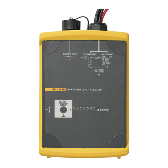
100 -350V 830 V MAX CAT 5 VA 600 V CAT 300 V CAT 1743 POWER LOGGER START STOP POWER egb021.eps Figure 2. 1744/1743 Power Quality Logger - Front View MyFlukeStore 1.877.766.5412 www. .com Shop for Fluke products online at:... - Page 25 Nominal ranges for the Flexi Set are 15 A, 150 A, 1500 A, and 3000 A ac. Nominal input for current clamps is 0.5 V. Continuously on = Logging in progress Logging status Blinking = Logging stopped or not started MyFlukeStore 1.877.766.5412 www. .com Shop for Fluke products online at:...
-
Page 26: Power Network Configurations
Profile of active, reactive, and apparent power versus time Monitoring of power factor (PF), and information about effectiveness of compensation systems Graphical representations of logging data and statistics MyFlukeStore 1.877.766.5412 www. .com Shop for Fluke products online at:... -
Page 27: Using The Logger
(quit logging when logging period is finished) Logging of current-neutral wire Converter ratios for current and voltage if using potential transformers (PTs) and current transformers (CTs) at a medium-voltage network site MyFlukeStore 1.877.766.5412 www. .com Shop for Fluke products online at:... -
Page 28: Preparing The Logger For Use
Logger power supply connections could be greater than 660 V RMS ac, plug the power supply leads into an outlet instead. Otherwise, you could damage the Logger. MyFlukeStore 1.877.766.5412 www. .com Shop for Fluke products online at:... - Page 29 POWER LOGGER START START STOP STOP POWER POWER egb031.eps Figure 3. Supplying Operating Power to the Logger 2. Connect the RS232 interface cable to the serial port of your PC. MyFlukeStore 1.877.766.5412 www. .com Shop for Fluke products online at:...
-
Page 30: Test Leads - Markings
Note Make sure the clip-on probes are connected to the appropriate phase: with I for a P-N measurement or V with I for a P-P measurement. MyFlukeStore 1.877.766.5412 www. .com Shop for Fluke products online at:... -
Page 31: Logging With Voltage Converters
660 V RMS The Logger is to be used and handled only by qualified personnel (see page 6). Maintenance work on the Logger must be done only by qualified service personnel. MyFlukeStore 1.877.766.5412 www. .com Shop for Fluke products online at:... - Page 32 3-phase 3-wire (Delta) systems (P-P): 120 V to 830 V WX Warning To avoid electrical shock, or damaging the Logger’s internal protective circuitry or weatherproof seal, do not open the Logger. MyFlukeStore 1.877.766.5412 www. .com Shop for Fluke products online at:...
- Page 33 4. Connect the current sensor to the conductor under test. 5. Connect the dolphin clips to the test leads. For 3-phase, 4-wire systems, connect the N-test lead first, and then the other phases. MyFlukeStore 1.877.766.5412 www. .com Shop for Fluke products online at:...
-
Page 34: Connections In 3-Phase 4-Wire (Wye) Systems
100 -350 V 830 V MAX CAT 5 VA 600 V CAT 300 V CAT 1743 POWER LOGGER START STOP POWER egb003.eps Figure 4. Logging in a 3-Phase 4-Wire (Wye) System MyFlukeStore 1.877.766.5412 www. .com Shop for Fluke products online at:... -
Page 35: Connections In 3-Phase 3-Wire (Delta) Systems
1743 POWER LOGGER START STOP POWER IP65 egb004.eps Figure 5. Logging in a 3-Phase 3-Wire (Delta) System The test lead N can be left open, or connected to ground potential. MyFlukeStore 1.877.766.5412 www. .com Shop for Fluke products online at:... -
Page 36: Connections For Single-Phase Logging
L 3 / C 45-65 Hz 100 -350V 830 V MAX CAT 5 VA 600 V CAT 300 V CAT 1743 POWER LOGGER START STOP POWER egb005.eps Figure 6. Single-Phase Logging MyFlukeStore 1.877.766.5412 www. .com Shop for Fluke products online at:... -
Page 37: Connections For Medium-Voltage Networks
MAX CAT 5 VA 600 V CAT 300 V CAT 1743 POWER LOGGER START STOP POWER egb006.eps Figure 7. Measuring 3-Phase Voltages in a 3-Wire (Delta) System with Three Voltage Converters MyFlukeStore 1.877.766.5412 www. .com Shop for Fluke products online at:... -
Page 38: Phase-Phase Delta Logging
2. In PQ Log, select the measuring range with the matching nominal voltage and P-P logging. 3. Enter the correct converter/transformer ratio for current and voltage. egb007.bmp Figure 8. PQ Log Settings for a 16 kV Network MyFlukeStore 1.877.766.5412 www. .com Shop for Fluke products online at:... -
Page 39: Phase-Ground, Wye-Logging
Figure 7 shows the Phase-Ground, Wye-Logging. Figure 9 shows typical PQ Log settings for using potential transformers (PTs) and current transformers (CTs) with a 16 kV network. egb010.bmp Figure 9. PQ Log Settings for a 16 kV Network MyFlukeStore 1.877.766.5412 www. .com Shop for Fluke products online at:... -
Page 40: Logging With Two Voltage Converters And Two Current Transformers
5 VA 600 V CAT 300 V CAT 1743 POWER LOGGER START STOP POWER egb009.eps Figure 10. Measuring 3-Phase Voltages in a 3-Wire System with Potential Transformers (Aron Measuring Circuit) MyFlukeStore 1.877.766.5412 www. .com Shop for Fluke products online at:... -
Page 41: Logging
START/STOP button once. As soon as the job is active, the LED is on continuously. If needed, the job can be cancelled after running for at least one minute, and restarted later. MyFlukeStore 1.877.766.5412 www. .com Shop for Fluke products online at:... -
Page 42: Completing The Logging Job
2. Remove the test leads of the three phases. Be sure to remove the measuring cable of the neutral wire last. 3. Remove the current probes. MyFlukeStore 1.877.766.5412 www. .com Shop for Fluke products online at:... -
Page 43: Evaluating The Logged Data
230 V ~, +20% 480 V ~, +20% 3-phase 4 wire Phase/Phase 120 V ~, +20% 200 V ~, +20% 400 V ~, +20% 830 V ~, +20% 3-phase 3 wire MyFlukeStore 1.877.766.5412 www. .com Shop for Fluke products online at:... -
Page 44: Signal Sampling
16-bit A/D converter. The sampling rate is 10.24 kHz. All parameters are calculated from this data. Resolution Accuracy Resolution and accuracy depend on the logging parameter. For details, see MyFlukeStore 1.877.766.5412 www. .com Shop for Fluke products online at:... -
Page 45: Voltage Variations
Figure 13. Measuring Voltage Variations Note For logging in Wye configuration using logging function A, the phase-phase voltages are measured and displayed separately from the logging of the phase-neutral voltages. MyFlukeStore 1.877.766.5412 www. .com Shop for Fluke products online at:... -
Page 46: Min/Max Values
The response time can be set in PQ Log to the following: 0.5 or 1 line power period 200 ms 1, 3, or 5 seconds. Max. Value Min. Value Measuring Interval egb017.jpg Figure 14. Logging Min and Max Values MyFlukeStore 1.877.766.5412 www. .com Shop for Fluke products online at:... -
Page 47: Voltage Interruptions
Interruptions > 10 ms (0.5 line power periods). The start time and duration of each interruption are registered. 110% Un 100% Un 90% Un Time Duration egb018.eps Figure 15. Voltage Interruption MyFlukeStore 1.877.766.5412 www. .com Shop for Fluke products online at:... -
Page 48: Voltage Dips And Swells
Logging function A records each individual voltage harmonic, up to the 50 order. These values are averaged over the interval length defined in PQ Log. MyFlukeStore 1.877.766.5412 www. .com Shop for Fluke products online at:... -
Page 49: Current Harmonics
183 Hz, the values will be corrected to 185 Hz. Interharmonics of voltages and currents with these frequencies are recorded. See the PQ Log manual for details. MyFlukeStore 1.877.766.5412 www. .com Shop for Fluke products online at:... -
Page 50: Thdv - In Function A
Function A: : RMS value of harmonic frequency #n. : RMS value of the fundamental frequency. THDI: total contents of harmonics of the current as a percentage of the fundamental. MyFlukeStore 1.877.766.5412 www. .com Shop for Fluke products online at:... -
Page 51: Calculation Of Thd In Measuring Function P
10 minutes, and is used to calculate the long-term (lt) flicker Plt (by taking the sliding average of 12 short-term values). The interval value can be changed as needed in PQ Log. MyFlukeStore 1.877.766.5412 www. .com Shop for Fluke products online at:... -
Page 52: Unbalance
The line power frequency is measured and averaged over 10 seconds, and the resulting values are divided into 42 classes for establishing statistics. Values are also averaged over the interval length defined in PQ Log. MyFlukeStore 1.877.766.5412 www. .com Shop for Fluke products online at:... -
Page 53: Current Logging
In logging function P, the active power, apparent power, and reactive power of the phases and total power of all three phases is calculated. Logging function A also calculates the distorting power D of the phases, and total MyFlukeStore 1.877.766.5412 www. .com Shop for Fluke products online at:... -
Page 54: Logger Parameters With Function P
∑ Active power per logging interval per phase : 200 ms value M: Number of 200 ms intervals per logging interval ∑ Total active power on all three total phases MyFlukeStore 1.877.766.5412 www. .com Shop for Fluke products online at:... - Page 55 ∑ Total apparent power on all three total phases Power factor per phase Total power factor on all three phases total total total total total total Tangent φ per phase MyFlukeStore 1.877.766.5412 www. .com Shop for Fluke products online at:...
- Page 56 (positive) and capacitive load (negative). Sign of PF, tan φ, cos φ: Sign “+” : Q positive (“inductive”) Sign “–” : Q negative (“capacitive”) independent of the sign of active power P MyFlukeStore 1.877.766.5412 www. .com Shop for Fluke products online at:...
-
Page 57: Logger Parameters With Function A
: RMS value of current harmonics of order n n: Order of the harmonics φ : Phase angle between current and voltage harmonics of order n : Harmonics of the active power of order n Fundamental ∑ MyFlukeStore 1.877.766.5412 www. .com Shop for Fluke products online at:... - Page 58 : 200 ms value bas j M: Number of 200 ms intervals per logging interval Total apparent power on ∑ three phases total k: Phase (k = 1, 2, 3) MyFlukeStore 1.877.766.5412 www. .com Shop for Fluke products online at:...
- Page 59 Total tangent φ on three phases total total total Active power of the fundamental per phase Basic value for 200 ms. Active power of the ∑ fundamental per phase per interval MyFlukeStore 1.877.766.5412 www. .com Shop for Fluke products online at:...
- Page 60 Active power accumulated on each logging interval and total Sign of PF, tan φ, cos φ: Sign “+” : Q positive (“inductive”) Sign “–” : Q negative (“capacitive”) independent of the sign of active power P MyFlukeStore 1.877.766.5412 www. .com Shop for Fluke products online at:...
-
Page 61: Maintenance
For locations of Fluke Service Centers worldwide and contact information, see the Fluke website: www.fluke.com. With proper use, the Logger does not require special maintenance other than periodic calibration at a Fluke calibration center. -
Page 62: Technical Specifications
Voltage harmonics Current harmonics (L1 or A, L2 or B, L3 or C, N, up to 50 order) Interharmonics, ripple-control signals THDV (voltage) THDI (current) CF (crest factor current) Unbalance Frequency MyFlukeStore 1.877.766.5412 www. .com Shop for Fluke products online at:... -
Page 63: Maximum Number Of Intervals For Logging Function P
Quality system Developed, designed, and manufactured according to DIN ISO 9001. Recalibration interval Fluke recommends a recalibration interval of no more than two years, depending on use. Reference conditions 23 C ± 2 K, 230 V ± 10% 50 Hz ± 0.1 Hz / 60 Hz ± 0.1 Hz... -
Page 64: Environmental Specifications
EN 61010-1 600 V CAT III, 300 V CAT IV pollution degree 2, double insulation Type test voltage 5.2 kV ac, 50 Hz / 60 Hz, 5 s Emission IEC/EN 61326-1, EN 55022 Immunity IEC/EN 61326-1 MyFlukeStore 1.877.766.5412 www. .com Shop for Fluke products online at:... -
Page 65: Power Supply
Averaging time for ½ , 1 line power period min/max values 200 ms 1, 3, 5 s Time base Resolution: 10 ms (at 50 Hz) deviation: 2 s/day at 23 °C. MyFlukeStore 1.877.766.5412 www. .com Shop for Fluke products online at:... -
Page 66: Input Voltage
Current transformer Ratio : ≤ 999 kA / I Ratio selection By job programming Connection 3-phase, 3-phase + N 2-phase L1 or A and L3 or C (2 W-meter-method) 7-pole connector MyFlukeStore 1.877.766.5412 www. .com Shop for Fluke products online at:... -
Page 67: Current Input For Clamp
Intrinsic uncertainty < 0.3% of I Max. overload 10 V ac Input resistance App. 8.2 ke Current transformer Ratio : ≤ 999 kA / ≤ I Ratio selection By job programming MyFlukeStore 1.877.766.5412 www. .com Shop for Fluke products online at:... -
Page 68: General Specifications
½ line power period Flicker Logging value Flicker severity (Pst / Plt) according to IEC 61000-4-15 Intrinsic uncertainty Pst < 5% of m. v Measuring range Pst 0.4 to 4 MyFlukeStore 1.877.766.5412 www. .com Shop for Fluke products online at:... -
Page 69: Power (Logging Functions A, P Only) P, S, |P
42 classes for 10 s mean values Ripple-control signals Interharmonics 21 classes for 3 s mean values Analysis of logging data Programming and analysis is done by PQ Log software on PC. MyFlukeStore 1.877.766.5412 www. .com Shop for Fluke products online at:... -
Page 70: Logging Function P
Long-term analysis of active, reactive, apparent power Long-term analysis of power factor, symmetry Disturbance analysis: Examination of voltage dips and swells, flicker measurement Network optimization: Load measurements, acceptance of new loads Efficiency of compensation systems MyFlukeStore 1.877.766.5412 www. .com Shop for Fluke products online at:... -
Page 71: Logging Function A - "All" Parameters
Absolute values active power |P| (mean, min, and max values) Distorting power D (mean, min, and max values) Apparent power S (mean, min, and max values) Power Factor PF, tangent Energy per averaging interval MyFlukeStore 1.877.766.5412 www. .com Shop for Fluke products online at:... -
Page 72: Applications
(e.g. current, voltage, and flicker), time of occurrence, periodicity Network Optimization: Load logging Current logging (with Flexi Set 5 to 3000 A or clamps 1 to 1000 A) Capture of current peaks MyFlukeStore 1.877.766.5412 www. .com Shop for Fluke products online at:... -
Page 73: Pq Log Pc Application Software
Setup: Internal clock (date/time) Define 1744/1743 Power Quality Logger designation Parameters for data export Software updates Analysis: ASCII data export Graphical summary of all EN 50160 parameters Online test function MyFlukeStore 1.877.766.5412 www. .com Shop for Fluke products online at:... -
Page 74: Online Test
1744/1743 Users Manual Online Test The following figure shows the online test display. egb024.bmp Figure 18. Online Test MyFlukeStore 1.877.766.5412 www. .com Shop for Fluke products online at:... -
Page 75: Ascii Export
Table of events (UNIPEDE DISDIP) Table summary Cumulative frequency, harmonics (logging function A only) Statistical values (logging function A only) All exceeding table (logging function A only) Most critical values (logging function A only) MyFlukeStore 1.877.766.5412 www. .com Shop for Fluke products online at:... -
Page 76: Timeplot Diagram
1744/1743 Users Manual Timeplot diagram The following figure shows a typical Timeplot diagram: egb026.bmp Figure 20. Timeplot Diagram MyFlukeStore 1.877.766.5412 www. .com Shop for Fluke products online at:... -
Page 77: Unipede Disdip Table
Power Quality Logger PQ Log PC Application Software UNIPEDE DISDIP Table The following figure shows a typical UNIPEDE DISDIP table: egb027.bmp Figure 21. UNIPEDE DISDIP Table MyFlukeStore 1.877.766.5412 www. .com Shop for Fluke products online at:... -
Page 78: Cumulative Frequency – Harmonics
Cumulative Frequency – Harmonics The following figure shows a typical display of cumulative frequencies for current and voltage harmonics: egb028.bmp Figure 22. Cumulative Frequency – For Voltage and Current Harmonics MyFlukeStore 1.877.766.5412 www. .com Shop for Fluke products online at:... - Page 79 Interharmonics, 11 THD V, 34 Interval length, 11 —U— I peak , 37 Unbalance, 36 —L— User Interface, 1 Limit values for events, 11 —V— Lithium Battery, 45 Voltage dips/swells, 32 MyFlukeStore 1.877.766.5412 www. .com Shop for Fluke products online at:...
- Page 80 1744/1743 Users Manual Voltage Harmonics, 32 Voltage interruptions, 31 Voltage variations, 28 MyFlukeStore 1.877.766.5412 www. .com Shop for Fluke products online at:...
Need help?
Do you have a question about the 1743-BASIC and is the answer not in the manual?
Questions and answers