IEI Technology WSB-9454 User Manual
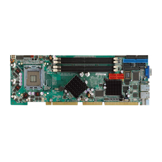
Picmg1.0 cpu card with lga775intel pentium d cpu, vga/dvi, dual pci-e gbe, sata ii, and audio
Hide thumbs
Also See for WSB-9454:
- User manual (146 pages) ,
- Quick installation manual (10 pages) ,
- Quick installation manual (9 pages)
Table of Contents
Advertisement
Quick Links
Advertisement
Chapters
Table of Contents

Related Manuals for IEI Technology WSB-9454


Summary of Contents for IEI Technology WSB-9454
- Page 1 WSB-9454 CPU Card Page i...
-
Page 2: Revision History
WSB-9454 CPU Card Revision History ® ® Model Name WSB-9454 Intel Pentium D CPU card Revision Number Description Date of Issue Initial release December 2006 COPYRIGHT NOTICE The information in this document is subject to change without prior notice in order to improve reliability, design and function and does not represent a commitment on the part of the manufacturer. -
Page 3: Table Of Contents
INTRODUCTION..................... 1 1.1 WSB-9454 CPU C ................2 VERVIEW 1.1.1 WSB-9454 Model Variations ................2 1.1.2 WSB-9454 CPU Card Applications ..............2 1.1.3 WSB-9454 CPU Card Benefits................2 1.1.4 WSB-9454 CPU Card Features ................. 3 1.2 WSB-9454 CPU C ................4 VERVIEW 1.2.1 WSB-9454 CPU Card Connectors .............. - Page 4 CONNECTORS AND JUMPERS ................. 25 3.1 P ..............26 ERIPHERAL NTERFACE ONNECTORS 3.1.1 WSB-9454 CPU Card Layout ................26 3.1.2 Peripheral Interface Connectors ..............28 3.1.3 External Peripheral Interface Connectors............29 3.1.4 On-board Jumper ..................... 30 3.2 I ..............30...
- Page 5 NSTALLATION ONSIDERATIONS 4.2.1 Installation Notices ..................68 4.3 U ......................69 NPACKING 4.3.1 Unpacking Precautions..................69 4.3.2 Checklist......................70 4.4 WSB-9454 CPU C ..............71 NSTALLATION 4.5 S LGA775 CPU I ..............72 OCKET NSTALLATION 4.5.1 CPU Selection: HT Functionality Requirements ..........72 4.5.1.1 CPU Installation..................
- Page 6 WSB-9454 CPU Card 4.8.2 VGA Port Installation ..................92 4.8.3 Ethernet Connection ..................92 4.8.4 USB Connection....................93 AMI BIOS SETUP....................95 5.1 I ......................96 NTRODUCTION 5.1.1 Starting Setup....................96 5.1.2 Using Setup ...................... 96 5.1.3 Getting Help..................... 97 5.1.4 Unable to Reboot after Configuration Changes ..........
- Page 7 WSB-9454 CPU Card SOFTWARE DRIVERS ..................155 6.1 A ................156 VAILABLE OFTWARE RIVERS 6.2 C ................156 HIPSET RIVER NSTALLATION 6.3 VGA D ......................161 RIVER 6.4 B LAN D E LAN) I ........166 ROADCOM RIVER NSTALLATION 6.5 R AC `97 (ALC655) A .........
- Page 8 WSB-9454 CPU Card E.9 S ..................207 PEAKER ONFIGURATION E.10 S ..................... 208 PEAKER E.11 S/PDIF-I & S/PDIF-O .................. 209 E.12 C ..................210 ONNECTOR ENSING E.13 HRTF D ....................... 213 E.14 M ..................213 ICROPHONE FFECT E.15 G ......................214 ENERAL INDEX..........................
- Page 9 WSB-9454 CPU Card List of Figures Figure 2-1: Data Flow Block Diagram................16 Figure 3-1: Connector and Jumper Locations ............27 Figure 3-2: ATX–12V Connector Location ..............31 Figure 3-3: Audio Module Connector Location ............33 Figure 3-4: Backplane to Mainboard Power Connector Location ......35 Figure 3-5: CPU Fan Connector Location..............37...
- Page 10 WSB-9454 CPU Card Figure 4-8: Connection of IDE Connector..............83 Figure 4-9: SATA Drive Cable Connection ...............85 Figure 4-10: SATA Drive Connection ................86 Figure 4-11: Dual RS-232 Cable Installation .............87 Figure 4-12: USB Cable Installation ................88 Figure 4-13 Jumper .....................89 Figure 4-14: Jumper Locations..................90 Figure 6-1: InstallShield Wizard Preparation Screen..........
- Page 11 WSB-9454 CPU Card Figure 6-22: AC`97 Audio Driver Welcome Screen..........175 Figure 6-23: AC`97 Audio Driver Software Configuration........176 Figure 6-24: AC`97 Audio Driver Digital Signal ............. 177 Figure 6-25: AC`97 Audio Driver Installation Begins..........178 Figure 6-26: AC`97 Audio Driver Installation Complete ........179...
- Page 12 WSB-9454 CPU Card List of Tables Table 1-1: WSB-9454 Model Variations ...............2 Table 1-2: WSB-9454 CPU Card Overview ..............4 Table 1-3: Technical Specifications ................8 Table 2-1: Supported CPUs ..................10 Table 2-2: Power Consumption..................22 Table 3-1: Peripheral Interface Connectors..............29 Table 3-2: External Peripheral Interface Connectors ..........29 Table 3-3: On-board Jumper ..................30...
- Page 13 WSB-9454 CPU Card Table 4-1: IEI Provided Cables ...................81 Table 4-2: On-board Jumpers ..................89 Table 4-3: Clear CMOS Jumper Settings ..............91 Table 5-1: BIOS Navigation Keys................97 Page xiii...
- Page 14 WSB-9454 CPU Card List of BIOS Menus BIOS Menu 1: Main......................98 BIOS Menu 2: Advanced..................100 BIOS Menu 3: CPU Configuration................101 BIOS Menu 4: IDE Configuration ................102 BIOS Menu 5: IDE Master and IDE Slave Configuration........104 BIOS Menu 6: Floppy Configuration ..............108 BIOS Menu 7: Super IO Configuration ..............
- Page 15 WSB-9454 CPU Card Glossary AC ’97 Audio Codec 97 Integrated Data Electronics ACPI Advanced Configuration and Input/Output Power Interface ICH4 I/O Controller Hub 4 Advanced Power Management Cache Level 1 Cache ARMD ATAPI Removable Media Device Cache Level 2 Cache...
-
Page 16: This Page Is Intentionally Left Blank
WSB-9454 CPU Card THIS PAGE IS INTENTIONALLY LEFT BLANK Page 16... -
Page 17: Introduction
WSB-9454 CPU Card Chapter Introduction Page 1... -
Page 18: Wsb-9454 Cpu Card Overview
Four Table 1-1: WSB-9454 Model Variations 1.1.2 WSB-9454 CPU Card Applications The WSB-9454 CPU card has been designed for use in industrial applications where board expansion is critical and operational reliability is essential. 1.1.3 WSB-9454 CPU Card Benefits Some of the WSB-9454 CPU card benefits include: ®... -
Page 19: Wsb-9454 Cpu Card Features
60°C rebooting automatically if the BIOS watchdog timer detects that the system is no longer operating 1.1.4 WSB-9454 CPU Card Features Some of the WSB-9454 CPU card features are listed below: PICMG 1.0 compliant RoHS compliant ®... -
Page 20: Wsb-9454 Cpu Card Overview
WSB-9454 CPU Card 1.2 WSB-9454 CPU Card Overview * See Table 1-1: for model variations. Table 1-2: WSB-9454 CPU Card Overview Page 4... -
Page 21: Wsb-9454 Cpu Card Connectors
WSB-9454 CPU Card 1.2.1 WSB-9454 CPU Card Connectors The WSB-9454 CPU card has the following connectors on-board: 1 x ATX-12V connector 1 x Audio module connector 1 x Backplane to mainboard power connector 1 x CPU fan connector 4 x DDR2 DIMM sockets... -
Page 22: Technical Specifications
WSB-9454 CPU Card 1.2.2 Technical Specifications WSB-9454 CPU card technical specifications are listed in Table 1-3:. Detailed descriptions of each specification can be found in Chapter 2. SPECIFICATION DESCRIPTION ® ™ Supported CPUs Intel Core 2 Duo ® ® Intel Pentium ®... - Page 23 WSB-9454 CPU Card SPECIFICATION DESCRIPTION ISA Bus Interface Supports three fully compatible ISA slots without buffering ISA DMA and ISA Bus Master function are not supported Serial ATA (SATA) Four SATA II channels with 300Mb/s transfer rates (see Table 1-1:)
-
Page 24: Table 1-3: Technical Specifications
WSB-9454 CPU Card SPECIFICATION DESCRIPTION Physical Dimensions 12.2cm x 34.1cm (width x length) Operating Temperature Minimum: 0ºC (32°F) Maximum: 60°C (140°F) Minimum: 5% Operating Humidity Maximum: 95% Optional Audio Interface 5.1 Channel audio kit with Realtek ALC655 AC `97 codec... -
Page 25: Detailed Specifications
WSB-9454 CPU Card Chapter Detailed Specifications Page 9... -
Page 26: Compatible Iei Backplanes
WSB-9454 CPU Card 2.1 Compatible IEI Backplanes The WSB-9454 CPU card is compatible with the all IEI PICMG1.0 backplanes. For more information on these backplanes, visit the IEI website or contact your CPU card reseller or vendor. 2.2 CPU Support Table 2-1 lists the CPUs supported by the WSB-9454 board. -
Page 27: Intel ® Pentium ® D
WSB-9454 CPU Card ® Intel Smart Cache Design allows two execution cores to share 2 MB of L2 cache, reducing FSB traffic and enhancing system responsiveness ® Intel Advanced Thermal Manager supports new digital temperature sensors and thermal monitors on each execution core to enhance thermal monitoring... -
Page 28: Intel ® Celeron ® D
WSB-9454 CPU Card ® ® 2.2.4 Intel Celeron ® ® The Intel Celeron D processor comes with the following features: ® Intel Extended Memory 64 Technology provides 64-bit computing support and extends virtual and physical memory, giving the processor platform... -
Page 29: Intel ® Ich7 Southbridge Chipset
WSB-9454 CPU Card ® 2.3.3 Intel ICH7 Southbridge Chipset ® The Intel ICH7 Southbridge chipset comes with the following features: Integrated serial ATA host controller with data transfer rates up to 3.0 Gb/s Integrated IDE Independent timing of up to two dirves... -
Page 30: Graphics Support
WSB-9454 CPU Card 2.4 Graphics Support ® 2.4.1 Intel GMA 950 ® ® The Intel GMA 950 integrated on the Intel 945G chipset has the following features. ® Intel GMA 950 Graphics Core 400MHz 256-bit graphics core Up to 10.6 GB/sec memory bandwidth with DDR2 667 MHz system memory 1.6 GPixels/sec and 1.6 GTexels/sec fill rate... -
Page 31: Digital Visual Interface (Dvi)
WSB-9454 CPU Card 2.4.3 Digital Visual Interface (DVI) The DVI interface on the WSB-9454DVI-R10 is controlled by the Silicon Image SiI362 chip and has the following features. ® Incorporates the latest PanelLink technology with support display resolutions ranging from VGA to UXGA (1600x1200) in a single link interface. -
Page 32: Data Flow
WSB-9454 CPU Card 2.5 Data Flow Figure 2-1 shows the data flow between the user-installed CPU, the two on-board chipsets, and other components installed on the CPU card. Figure 2-1: Data Flow Block Diagram Page 16... -
Page 33: Memory Support
WSB-9454 CPU Card 2.6 Memory Support The WSB-9454 CPU card has two 240-pin dual inline memory module (DIMM) sockets that support up to two unbuffered DDR2 DIMMs with the following specifications: Maximum RAM: 2GB (1GB module in each slot) DIMM Transfer Rates: 667MHz, 533MHz, 400MHz Up to 10.6 GB/sec memory bandwidth... -
Page 34: Drive Interfaces
Serial EEPROM or serial flash supported JTAG supported 196-FBGA package 2.9 Drive Interfaces The WSB-9454-R10 model supports the following drive interfaces: 2 x SATA II drives 1 x IDE channel supports two Ultra ATA 100/66/33 devices 1 x FDD The WSB-9454DVI-R10 model supports the following drive interfaces:... -
Page 35: Sata Drives
WSB-9454 CPU Card 2.9.1 SATA Drives The WSB-9454 supports the SATA II drive interfaces with transfer rates up to 300Mb/s with the ICH7 Southbridge chipset. 2.9.2 IDE HDD Interfaces The IDE controller on the ICH7 Southbridge chipset integrated on the CPU card supports... -
Page 36: Serial Ports
If you want to use the IrDA port, you have to configure SIR or ASKIR mode in the BIOS under Super IO devices. The normal RS-232 COM2 will be disabled. 2.14 USB Interfaces The WSB-9454 CPU card has seven USB interfaces, six internal and one external. The USB interfaces support USB 2.0. Page 20... -
Page 37: Bios
WSB-9454 CPU Card 2.15 BIOS The WSB-9454 CPU card uses a licensed copy of AMI BIOS. The features of the flash BIOS used are listed below: SMIBIOS (DMI) compliant Console redirection function support PXE (Pre-Boot Execution Environment) support USB booting support 2.16 Operating Temperature and Temperature Control... -
Page 38: Power Consumption
WSB-9454 CPU Card 2.18 Power Consumption Table 2-2 shows the power consumption parameters for the WSB-9454 CPU card when a ® ® 3GHz Intel Pentium 4 processor is running with four 1GB, DDR2 533MHz SDRAM memory modules. Voltage Current 6.75A +12V 7.24A... -
Page 39: Optional Accessory Items
WSB-9454 CPU Card 2.19.3 Optional Accessory Items The items shown in the list below are separately purchased optional accessory items. DVI cable Audio kit CPU cooler FDD cable LPT cable Page 23... - Page 40 WSB-9454 CPU Card THIS PAGE IS INTENTIONALLY LEFT BLANK Page 24...
-
Page 41: Connectors And Jumpers
WSB-9454 CPU Card Chapter Connectors and Jumpers Page 25... -
Page 42: Peripheral Interface Connectors
The location of the peripheral interface connectors are shown in Section 3.1.1. A complete list of all the peripheral interface connectors can be seen in Section 3.2. 3.1.1 WSB-9454 CPU Card Layout Figure 3-1 shows the on-board peripheral connectors, backplane peripheral connectors and on-board jumpers. -
Page 43: Figure 3-1: Connector And Jumper Locations
WSB-9454 CPU Card Figure 3-1: Connector and Jumper Locations Page 27... -
Page 44: Peripheral Interface Connectors
WSB-9454 CPU Card 3.1.2 Peripheral Interface Connectors Table 3-1 lists the peripheral interface connectors on the WSB-9454 CPU card. Detailed descriptions of these connectors can be found in Section 3.2. Label Connector Type CPU12V1 ATX-12V CPU Power Source 4-pin terminal block... -
Page 45: External Peripheral Interface Connectors
USB23 USB Connectors USB45 Table 3-1: Peripheral Interface Connectors 3.1.3 External Peripheral Interface Connectors Table 3-2 lists the external peripheral interface connectors on the WSB-9454. Detailed descriptions of these connectors can be found in Section 3.3. Connector Type Label Ethernet connectors... -
Page 46: On-Board Jumper
Internal peripheral connectors are found on the CPU card and are only accessible when the CPU card is outside of the chassis. This section has complete descriptions of all the internal peripheral connectors on the WSB-9454 CPU card. 3.2.1 ATX-12V Power Source Connector... -
Page 47: Figure 3-2: Atx-12V Connector Location
WSB-9454 CPU Card Figure 3-2: ATX–12V Connector Location PIN NO. DESCRIPTION PIN NO. DESCRIPTION +12V +12V Table 3-4: ATX–12V Connector Pinouts Page 31... -
Page 48: Audio Module Connector
CN Location: See Figure 3-3 CN Pinouts: See Table 3-5 The WSB-9454 CPU card does not have a built-in AC’97 audio codec. If your system needs audio then this connector must be connected to an external audio module (AC-KIT-08R). Page 32... -
Page 49: Figure 3-3: Audio Module Connector Location
WSB-9454 CPU Card Figure 3-3: Audio Module Connector Location Page 33... -
Page 50: Backplane To Mainboard Power Connector
WSB-9454 CPU Card PIN NO. DESCRIPTION PIN NO. DESCRIPTION SYNC BITCLK SDOUT PCBEEP SDIN RST# +12V Table 3-5: Audio Module Connector Pinouts 3.2.3 Backplane to Mainboard Power Connector CN Label: ATXCTL1 3-pin wafer connector CN Type: CN Location: See Figure 3-4... -
Page 51: Figure 3-4: Backplane To Mainboard Power Connector Location
WSB-9454 CPU Card Figure 3-4: Backplane to Mainboard Power Connector Location PIN NO. DESCRIPTION ATX-ON 5VSB Table 3-6: Backplane to Mainboard Power Pinouts Page 35... -
Page 52: Cpu Fan Connector
WSB-9454 CPU Card 3.2.4 CPU Fan Connector CN Label: CPU_FAN1 CN Type: 4-pin wafer connector CN Location: See Figure 3-5 CN Pinouts: See Table 3-7 The cooling fan connector provides a 12V, 500mA current to a CPU cooling fan. The connector has a "rotation"... -
Page 53: Figure 3-5: Cpu Fan Connector Location
WSB-9454 CPU Card Figure 3-5: CPU Fan Connector Location DESCRIPTION Ground +12V Rotation Signal Control Table 3-7: CPU Fan Connector Pinouts Page 37... -
Page 54: Digital Input/Output (Dio) Connector
WSB-9454 CPU Card 3.2.5 Digital Input/Output (DIO) Connector CN Label: DIO1 CN Type: 10-pin header CN Location: See Figure 3-6 CN Pinouts: See Table 3-8 The DIO connector is managed through a Super I/O chip. The DIO connector pins are user programmable. -
Page 55: Figure 3-6: Dio Connector Location
WSB-9454 CPU Card Figure 3-6: DIO Connector Location Page 39... -
Page 56: Dvi (Digital Visual Interface) Connector
WSB-9454 CPU Card PIN NO. DESCRIPTION PIN NO. DESCRIPTION Ground Output 0 Output 1 Output 2 Output 3 Input 0 Input 1 Input 2 Input 3 Table 3-8: DIO Connector Pinouts 3.2.6 DVI (Digital Visual Interface) Connector CN Label: DVI1... -
Page 57: Figure 3-7: Dvi Connector Location
WSB-9454 CPU Card Figure 3-7: DVI Connector Location PIN NO. DESCRIPTION PIN NO. DESCRIPTION Data 2- Data 2+ Hot Plug Detect. Data 0- Data 0+ DDC Clock Page 41... -
Page 58: Fdd Connector
3.2.7 FDD Connector CN Label: FDD1 CN Type: 34-pin header CN Location: See Figure 3-8 CN Pinouts: See Table 3-10 The WSB-9454 is shipped with a 34-pin daisy-chain drive connector cable. This cable can be connected to the FDD connector. Page 42... -
Page 59: Figure 3-8: Fdd Connector Location
WSB-9454 CPU Card Figure 3-8: FDD Connector Location DESCRIPTION DESCRIPTION REDUCE WRITE INDEX# MOTOR ENABLE A# Page 43... -
Page 60: Front Panel Connector
WSB-9454 CPU Card DRIVE SELECT B# DRIVE SELECT A# MOTOR ENABLE B# DIRECTION# STEP# WRITE DATA# WRITE GATE# TRACK 0# WRITE PROTECT# READ DATA# SIDE 1 SELECT# DISK CHANGE# Table 3-10: FDD Connector Pinouts 3.2.8 Front Panel Connector CN Label:... -
Page 61: Figure 3-9: Front Panel Connector Location
WSB-9454 CPU Card Figure 3-9: Front Panel Connector Location Page 45... -
Page 62: Ide Connector
WSB-9454 CPU Card FUNCTION DESCRIPTION FUNCTION DESCRIPTION PWR_LED+ SPKR+ Power LED Speaker PWR_LED- PWR_BTN+ SPKR- PWRBTN RESET PWR_BTN- HDD_LED+ RESET+ HDDLED HDD_LED- RESET- Table 3-11: Front Panel Connector Location 3.2.9 IDE Connector CN Label: PIDE1 40-pin box header CN Type:... -
Page 63: Figure 3-10: Ide Connector Location
WSB-9454 CPU Card Figure 3-10: IDE Connector Location Page 47... -
Page 64: Table 3-12: Ide Connector Pinouts
WSB-9454 CPU Card DESCRIPTION DESCRIPTION RESET# DATA 7 DATA 8 DATA 6 DATA 9 DATA 5 DATA 10 DATA 4 DATA 11 DATA 3 DATA 12 DATA 2 DATA 13 DATA 1 DATA 14 DATA 0 DATA 15 IDE DRQ... -
Page 65: Irda Interface Connector
WSB-9454 CPU Card 3.2.10 IrDA Interface Connector CN Label: CN Type: 5-pin header CN Location: See Figure 3-11 CN Pinouts: See Table 3-13 The integrated IrDA interface connector supports both the SIR and ASKIR infrared protocols. Page 49... -
Page 66: Figure 3-11: Irda Interface Connector Location
WSB-9454 CPU Card Figure 3-11: IrDA Interface Connector Location Page 50... -
Page 67: Keyboard Connector
WSB-9454 CPU Card DESCRIPTION SIN1_IRRX SOUT1_IRTX Table 3-13: IrDA Interface Connector Pinouts 3.2.11 Keyboard Connector CN Label: CN Type: 4-pin wafer CN Location: See Figure 3-12 CN Pinouts: See Table 3-14 For alternative application, a keyboard pin header connector is also available on board. -
Page 68: Figure 3-12: Keyboard Connector Location
WSB-9454 CPU Card Figure 3-12: Keyboard Connector Location Page 52... -
Page 69: Parallel Port Connector
WSB-9454 CPU Card DESCRIPTION Keyboard Clock Keyboard Data Table 3-14: KB1 Connector Pinouts 3.2.12 Parallel Port Connector CN Label: LPT1 CN Type: 25-pin box header CN Location: See Figure 3-13 CN Pinouts: See Table 3-15 The parallel port connector is usually connected to a printer or other parallel device with a 26-pin flat-cable connector. -
Page 70: Figure 3-13: Parallel Port Connector Location
WSB-9454 CPU Card Figure 3-13: Parallel Port Connector Location DESCRIPTION DESCRIPTION STROBE# AUTO FORM FEED # DATA0 ERROR# DATA1 INITIALIZE# DATA2 PRINTER SELECT LN# DATA3 DATA4 Page 54... -
Page 71: Serial Port Connectors
3.2.13 RS-232 Serial Port Connectors CN Label: COM1, COM2 CN Type: 10-pin box header CN Location: See Figure 3-14 CN Pinouts: See Table 3-16 The WSB-9454 CPU card has two internal high-speed UART connectors accessed through a 10-pin cable connector. Page 55... -
Page 72: Figure 3-14: Rs-232 Serial Port Connectors Location
WSB-9454 CPU Card Figure 3-14: RS-232 Serial Port Connectors Location Page 56... -
Page 73: Sata Drive Connectors
WSB-9454 CPU Card DESCRIPTION DESCRIPTION DATA CARRIER DETECT (DCD) DATA SET READY (DSR) RECEIVE DATA (RXD) REQUEST TO SEND (RTS) TRANSMIT DATA (TXD) CLEAR TO SEND (CTS) DATA TERMINAL READY (DTR) RING INDICATOR (RI) GND (GND) GND (GND) Table 3-16: RS-232 Serial Port Connectors Pinouts 3.2.14 SATA Drive Connectors... -
Page 74: Figure 3-15: Sata Connectors Location
WSB-9454 CPU Card Figure 3-15: SATA Connectors Location DESCRIPTION DESCRIPTION Table 3-17: SATA Connectors Pinouts Page 58... - Page 75 WSB-9454 CPU Card CAUTION: Your SATA hard drives may come with both a 4P power connector and a SATA power interface. Attach either the 4P connector or the included DO NOT SATA power cable to your SATA hard drives. attach both the power connectors to your SATA hard drives at the same time! Doing so will cause damage.
-
Page 76: Usb Connectors
WSB-9454 CPU Card 3.2.15 USB Connectors CN Label: USB01, USB23, USB45 CN Type: 8-pin header CN Location: See Figure 3-16 CN Pinouts: See Table 3-18 Three 2x4 pin connectors provide connectivity to six USB 2.0 ports. An additional USB port is found on the rear panel. The USB ports are used for I/O bus expansion. -
Page 77: Figure 3-16: Usb Port Connector Location
WSB-9454 CPU Card Figure 3-16: USB Port Connector Location Page 61... -
Page 78: External Peripheral Interface Connectors
Table 3-18: USB Port Connector Pinouts 3.3 External Peripheral Interface Connectors Figure 3-17 shows the WSB-9454 CPU card rear panel. The peripheral connectors on the back panel can be connected to devices externally when the CPU card is installed in a chassis. -
Page 79: Lan Connectors
CN Pinouts: See Table 3-19 The WSB-9454 is equipped with two built-in GbE Ethernet controllers. The controllers can connect to the LAN through two RJ-45 LAN connectors. There are two LEDs on the connector indicating the status of LAN. The pin assignments are listed in the following table: PIN NO. -
Page 80: Mini-Din 6 Ps/2 Connector
WSB-9454 CPU Card STATUS DESCRIPTION STATUS DESCRIPTION GREEN Activity YELLOW Linked Table 3-20: RJ-45 Ethernet Connector LEDs 3.3.2 Mini-DIN 6 PS/2 Connector CN Label: KB_MS1 CN Type: Mini-DIN 6 PS/2 CN Location: See Figure 3-17 (labeled number 1) CN Pinouts:... -
Page 81: Usb Connector
CN Type: CN Location: See Figure 3-17 (labeled number 3) CN Pinouts: See Table 3-22 The WSB-9454 has one rear panel USB port. This port connects to both USB 2.0 and USB 1.1 devices. PIN NO. DESCRIPTION DATA- DATA+ GROUND... -
Page 82: Vga Connector
WSB-9454 CPU Card 3.3.4 VGA connector CN Label: VGA1 CN Type: HD-D-sub 15 female connector CN Location: See Figure 3-17 (labeled number 4) CN Pinouts: See Table 3-23 A 15-pin VGA connector connects to standard displays. Figure 3-20: VGA Connector PIN NO. -
Page 83: Installation And Configuration
WSB-9454 CPU Card Chapter Installation and Configuration Page 67... -
Page 84: Anti-Static Precautions
CPU card and injury to the person installing the CPU card. 4.2.1 Installation Notices Before and during the installation of the WSB-9454 CPU card, please do the following: Read the user manual The user manual provides a complete description of the WSB-9454 CPU card, installation instructions and configuration options. -
Page 85: Unpacking
Before you install the WSB-9454 CPU card, you must unpack the CPU card. Some components on WSB-9454 are very sensitive to static electricity and can be damaged by a sudden rush of power. To protect it from being damage, follow these precautions:... -
Page 86: Checklist
You can do so by wearing a grounded wrist strap at all times or by frequently touching any conducting materials that is connected to the ground. Handle your WSB-9454 by its edges. Do not touch the IC chips, leads or circuitry if not necessary. -
Page 87: Wsb-9454 Cpu Card Installation
4.4 WSB-9454 CPU Card Installation WARNING: Never run the CPU card without an appropriate heatsink and cooler that can be ordered from IEI Technology or purchased separately. Be sure to use the CPU 12V power connector (CPU12V1) for the CPU power. -
Page 88: Socket Lga775 Cpu Installation
Make sure the CPU is installed properly and ensure that a heat sink and CPU cooling fan are properly installed before the WSB-9454 is run. If a heat sink and cooling fan are not properly installed both the CPU and the board may be damaged. -
Page 89: Figure 4-1: Intel ® Lga775 Socket
When handling the CPU, only hold it on the sides. DO NOT touch the pins at the bottom of the CPU. To install Socket LGA775 CPU onto the WSB-9454, follow the steps below: Step 1: Remove the protective cover. Remove the black protective cover by prying it off the load plate. -
Page 90: Figure 4-2: Remove The Cpu Socket Protective Shield
WSB-9454 CPU Card Figure 4-2: Remove the CPU Socket Protective Shield Step 2: Open the socket. Disengage the load lever by pressing the lever down and slightly outward to clear the retention tab. Rotate the load lever to a fully open position. -
Page 91: Figure 4-4: Insert The Socket Lga775 Cpu
WSB-9454 CPU Card Step 5: Correctly position the CPU. Match the Pin 1 mark with the cut edge on the CPU socket. Step 6: Align the CPU pins. Locate pin 1 and the two orientation notches on the CPU. Carefully match the two orientation notches on the CPU with the socket alignment keys. -
Page 92: Socket Lga775 Cooling Kit (Cf-520) Installation
It is strongly recommended that you DO NOT use the original heat sink and cooler provided by Intel on the WSB-9454. The WSB-9454 is vertically mounted on a horizontal backplane. Intel’s heat sink does not come with a support bracket on the soldering side, so the PCB may be bent by the weight of the cooling kit. - Page 93 WSB-9454 CPU Card NOTE: Do not wipe off (accidentally or otherwise) the pre-sprayed layer of thermal paste on the bottom of the heat sink. The thermal paste between the CPU and the heat sink is important for optimum heat dissipation.
-
Page 94: Figure 4-6: Securing The Heat Sink To The Pcb
Step 6: Connect the fan cable. Connect the cooling kit fan cable to the fan connector on the WSB-9454. Carefully route the cable and avoid heat generating chips and fan blades.Step 0:... -
Page 95: Dimm Module Installation
WSB-9454 CPU Card 4.5.3 DIMM Module Installation 4.5.3.1 Purchasing the Memory Module WARNING: When purchasing the DIMM modules, make sure the modules are compatible with the DIMM slot specified in Section 2.6 Memory Support. WARNING: The board supports DDR2 DIMM modules only. DDR1 and DDR2 are not compatible. -
Page 96: Dimm Module Installation
WSB-9454 CPU Card 4.5.3.2 DIMM Module Installation The WSB-9454 CPU card has four 240-pin DDR2 SDRAM DIMM sockets. To install the DIMM modules, follow the instructions below. Step 1: Make sure the two handles of the DIMM socket are in the "open" position, leaning outward (Figure 4-7). -
Page 97: Peripheral Device Connection
WSB-9454 CPU Card Step 2: Slowly slide the DIMM module along the plastic guides on both ends of the socket. Press the DIMM module down into the socket until it clicks into position and the two handles have automatically locked the memory module into place. -
Page 98: Ide Drive Connector (Pide1)
WSB-9454 CPU Card 4.5.4.1 IDE Drive Connector (PIDE1) The cable used to connect the motherboard to the IDE device is a standard 40-pin ATA/100 flat cable. To connect an IDE device to the motherboard, follow the instructions below. Step 1: Find the IDE flat cable in the kit that came with the motherboard. -
Page 99: Figure 4-8: Connection Of Ide Connector
WSB-9454 CPU Card Figure 4-8: Connection of IDE Connector NOTE: When two IDE disk drives are connected together, back-end jumpers on the drives must be used to configure one drive as a master and the other as a slave. Page 83... -
Page 100: Floppy Drive Connector (Fdd1)
WSB-9454 CPU Card 4.5.4.2 Floppy Drive Connector (FDD1) This connector provides access to an externally mounted 3.5” floppy drive. To connect the CPU Card to a FDD, follow the instructions below. Step 1: Insert one side of the cable into the FDC making sure that the red wire on the cable corresponds to pin 1 on the connector. -
Page 101: Figure 4-9: Sata Drive Cable Connection
WSB-9454 CPU Card Figure 4-9: SATA Drive Cable Connection Step 3: Connect the connector on the other end of the cable to the connector at the back of the SATA drive (Figure 4-10). Step 4: Connect the SATA power connector to the back of the SATA drive (Figure 4-10). -
Page 102: Installing The Rs-232 Cable
WSB-9454 CPU Card Figure 4-10: SATA Drive Connection 4.5.4.4 Installing the RS-232 Cable A dual RS-232 cable consisting of two cables attached to two D-sub 9 male connectors that are mounted onto a bracket can be connected to the COM1 and COM2 RS-232 connectors. -
Page 103: Usb 2.0 Cable Connection
WSB-9454 CPU Card Figure 4-11: Dual RS-232 Cable Installation Step 3: Secure the bracket supporting the two D-sub 9 male connectors to the chassis. To do this, refer to the chassis manual. Step 0: 4.5.4.5 USB 2.0 Cable Connection The CPU card is shipped with a dual USB cable. The dual USB cable consists of two connectors attached to two independent cables. -
Page 104: Figure 4-12: Usb Cable Installation
WSB-9454 CPU Card Step 2: Insert the two 4-pin connectors from the module into the USB pin headers on the CPU card. (Figure 4-12) Step 0: Figure 4-12: USB Cable Installation Page 88... -
Page 105: On-Board Jumper
WSB-9454 CPU Card 4.6 On-board Jumper NOTE: A jumper is a metal bridge that is used to close an electrical circuit. It consists of two metal pins and a small metal clip (often protected by a plastic cover) that slides over the pins to connect them. -
Page 106: Figure 4-14: Jumper Locations
WSB-9454 CPU Card Figure 4-14: Jumper Locations Page 90... -
Page 107: Clear Cmos Jumper
WSB-9454 CPU Card 4.6.1 Clear CMOS Jumper Jumper Label: J_CMOS1 Jumper Type: 3-pin header Jumper Settings: See Table 4-3 Jumper Location: See Figure 4-14 If the CPU card fails to boot due to improper BIOS settings, use this jumper to clear the CMOS data and reset the system BIOS information. -
Page 108: Chassis Installation
WSB-9454 CPU Card 4.7 Chassis Installation After the CPU, the cooling kit, and the DIMM modules have been installed and after the internal peripheral connectors have been connected to the peripheral devices and the jumpers have been configure, the CPU card can be mounted into a chassis. -
Page 109: Usb Connection
WSB-9454 CPU Card 4.8.4 USB Connection The rear panel USB connector provides easier and quicker access to external USB devices. The rear panel USB connector is a standard connector and can easily be connected to other USB devices. Page 93... - Page 110 WSB-9454 CPU Card THIS PAGE IS INTENTIONALLY LEFT BLANK Page 94...
-
Page 111: Ami Bios Setup
WSB-9454 CPU Card Chapter AMI BIOS Setup Page 95... -
Page 112: Introduction
WSB-9454 CPU Card 5.1 Introduction A licensed copy of AMI BIOS is preprogrammed into the ROM BIOS. The BIOS setup program allows users to modify the basic system configuration. This chapter describes how to access the BIOS setup program and the configuration options that may be changed. -
Page 113: Getting Help
WSB-9454 CPU Card F1 key General help, only for Status Page Setup Menu and Option Page Setup Menu F2 /F3 key Change color from total 16 colors. F2 to select color forward. F10 key Save all the CMOS changes, only for Main Menu Table 5-1: BIOS Navigation Keys 5.1.3 Getting Help... -
Page 114: Main
WSB-9454 CPU Card 5.2 Main When the BIOS Setup program is entered, the Main menu (BIOS Menu 1) appears. The Main menu gives an overview of the basic system information. BIOS Menu 1: Main System Overview The System Overview lists a brief summary of different system components. The fields in System Overview cannot be changed. -
Page 115: Advanced
WSB-9454 CPU Card Processor: Displays auto-detected CPU specifications Type: Names the currently installed processor Speed: Lists the processor speed Count: The number of CPUs on the motherboard System Memory: Displays the auto-detected system memory. Size: Lists memory size The System Overview field also has two user configurable fields: System Time [xx:xx:xx]: The system time is set here. -
Page 116: Bios Menu 2: Advanced
WSB-9454 CPU Card BIOS Menu 2: Advanced Page 100... -
Page 117: Cpu Configuration
WSB-9454 CPU Card 5.3.1 CPU Configuration The CPU Configuration menu (BIOS Menu 3) shows detailed CPU specifications and CPU configuration options. BIOS Menu 3: CPU Configuration The CPU Configuration menu (BIOS Menu 3) lists the following CPU details: Manufacturer: Lists the name of the CPU manufacturer... -
Page 118: Ide Configuration
WSB-9454 CPU Card 5.3.2 IDE Configuration The IDE Configuration menu (BIOS Menu 4) allows changes to the configurations for the IDE devices installed in the system. BIOS Menu 4: IDE Configuration ATA/IDE Configuration [Compatible] The ATA/IDE Configuration BIOS option allows the user to configure the ATA/IDE device mode. -
Page 119: Legacy Ide Channels [Sata Pri, Pata Sec]
WSB-9454 CPU Card Disable all ATA/IDE ports. No Primary/Secondary IDE Disabled mode is presented for configuration Compatible Up to 4 HDDs can be used, two for SATA and the other EFAULT for PATA IDE. If this option is selected, “Legacy IDE Channels”... -
Page 120: Ide Master, Ide Slave
WSB-9454 CPU Card Primary IDE Slave Secondary IDE Master Secondary IDE Slave The IDE Configuration menu (BIOS Menu 4) allows changes to the configurations for the IDE devices installed in the system. If an IDE device is detected, and one of the above listed four BIOS configuration options are selected, the IDE configuration options shown in Section 5.3.2.1 appear. -
Page 121: Type [Auto]
WSB-9454 CPU Card Type [Auto] The Type BIOS option determines the type of device that the AMIBIOS attempts to boot from after the Power-On Self-Test (POST) has completed. Not Installed Selecting this value prevents the BIOS from searching for an IDE disk drive on the specified channel. -
Page 122: Block (Multi Sector Transfer) [Auto]
WSB-9454 CPU Card This selection prevents the BIOS from using the LBA Disabled mode control on the specified channel. Auto This option allows the BIOS to auto detect the LBA mode EFAULT control on the specified channel. Block (Multi Sector Transfer) [Auto]... -
Page 123: Dma Mode [Auto]
WSB-9454 CPU Card PIO mode 3 selected with a maximum transfer rate of 11.1MBps PIO mode 4 selected with a maximum transfer rate of 16.6MBps (This setting generally works with all hard disk drives manufactured after 1999. For other disk drives, such as IDE CD-ROM drives, check the specifications of the drive.) -
Page 124: Floppy Configuration
WSB-9454 CPU Card Prevents the BIOS from using 32-bit data transfers. Disabled Enabled Allows BIOS to use 32-bit data transfers on support hard EFAULT disk drives. 5.3.3 Floppy Configuration Use the Floppy Configuration menu (BIOS Menu 6) to set or change the configurations for floppy disk drives. -
Page 125: Super Io Configuration
WSB-9454 CPU Card Floppy A/B [1.44 MB 3½”] The Floppy A/B configuration option determines the types of the floppy drive installed in the system. The following configuration options are available. Disabled 360 KB 5¼” 1.2 MB 5¼” 720 KB 3 ½”... -
Page 126: On-Board Floppy Controller [Enabled]
WSB-9454 CPU Card On-board Floppy Controller [Enabled] Use the On-board Floppy Controller to enable or disable the floppy controller. If a floppy disk is not being used in the system, disabling this option frees up system resources that can be redirected elsewhere in the system. -
Page 127: Serial Port2 Address [2F8/Irq3]
WSB-9454 CPU Card Serial Port2 Address [2F8/IRQ3] The Serial Port2 Address option allows BIOS to select the Serial Port 2 base address. Disabled No base address is assigned to Serial Port 2 2F8/IRQ3 Serial Port 2 I/O port address is 3F8 and the interrupt... -
Page 128: Parallel Port Address [378]
WSB-9454 CPU Card Parallel Port Address [378] Use the Parallel Port Address option to select the parallel port base address. Disabled No base address is assigned to the Parallel Port Parallel Port I/O port address is 378 EFAULT Parallel Port I/O port address is 278... -
Page 129: Parallel Port Irq [Irq7]
WSB-9454 CPU Card The parallel port operates in the extended capabilities port (ECP) mode. The ECP mode supports bi-directional communication between the system and the parallel port device and the transmission rates between the two are much faster than the Normal mode ECP+EPP The parallel port operates in ECP and EPP modes. -
Page 130: Hardware Health Configuration
WSB-9454 CPU Card 5.3.5 Hardware Health Configuration The Hardware Health Configuration menu (BIOS Menu 8) shows the operating temperature, fan speeds and system voltages. BIOS Menu 8: Hardware Health Configuration Page 114... -
Page 131: Cpu Fan Mode Setting: [Manual Mode]
WSB-9454 CPU Card CPU FAN Mode Setting: [Manual Mode] The CPU FAN Mode Setting has the following options: Manual mode When the CPU FAN Mode Setting is set to EFAULT Manual Mode, the user is allowed to manually set the PWM duty cycle value. If selected, the... -
Page 132: Cpufan0 Targetspeed Value
WSB-9454 CPU Card Speed Cruise When the CPU FAN Mode Setting is set to Mode Speed Cruise Mode, the CPU fan runs at a predefined speed. If selected, the following options will appear with values that can be configured: CPUFAN0 TargetSpeed Value... -
Page 133: Acpi Configuration
WSB-9454 CPU Card 5.3.6 ACPI Configuration The ACPI Configuration menu (BIOS Menu 9) configures the Advanced Configuration and Power Interface (ACPI) and Power Management (APM) options. BIOS Menu 9: ACPI Configuration ACPI Aware O/S [Yes] Use the ACPI Aware O/S option to enable the system to configure ACPI power saving options. -
Page 134: General Acpi Configuration
WSB-9454 CPU Card Disables the ACPI support for the OS. This selection should be disabled if the OS does not support ACPI Enables the ACPI support for the operating system. This EFAULT selection should be enabled if the OS does support ACPI 5.3.6.1 General ACPI Configuration... -
Page 135: Suspend Mode [Auto]
WSB-9454 CPU Card Suspend mode [Auto] Use the Suspend Mode option to specify the sleep state the system enters when it is not being used. Auto The OS selects the sleep state when then system is not EFAULT being used. -
Page 136: Apm Configuration
WSB-9454 CPU Card 5.3.7 APM Configuration Use the APM Configuration menu (BIOS Menu 11) to select the advanced power management. BIOS Menu 11: APM Configuration Power Management/APM [Enabled] The Power Management/APM BIOS option accesses the advanced power management features. Page 120... -
Page 137: Power Button Mode [On/Off]
WSB-9454 CPU Card Disables the Advanced Power Management (APM) Disabled feature Enabled Enables the APM feature EFAULT Power Button Mode [On/Off] The Power Button Mode BIOS specifies how the power button functions. When the power button is pressed the system is either... -
Page 138: Rtc Alarm Date (Days)
WSB-9454 CPU Card The real time clock (RTC) cannot generate a wake Disabled EFAULT event Enabled If selected, the following will appear with values that can be selected: RTC Alarm Date (Days) RTC Alarm Time After setting the alarm, the computer will turn itself on from a suspend state when the alarm goes off. -
Page 139: Mps Configuration
WSB-9454 CPU Card 5.3.8 MPS Configuration Use the MPS Configuration menu (BIOS Menu 12) to select the multi-processor table. BIOS Menu 12: MPS Configuration MPS Revision [1.4] Use the Multiprocessor Specification (MPS) Revision option to specify the MPS version to be used. -
Page 140: Usb Configuration
WSB-9454 CPU Card 5.3.9 USB Configuration Use the USB Configuration menu (BIOS Menu 13) to read USB configuration information and configure the USB settings. BIOS Menu 13: USB Configuration USB Configuration The USB Configuration field shows the system USB configuration. The items listed are: Module Version: x.xxxxx.xxxxx... -
Page 141: Port 64/60 Emulation [Disabled]
WSB-9454 CPU Card Use the Legacy USB Support BIOS option to enable USB mouse and USB keyboard support. Normally if this option is not enabled, any attached USB mouse or USB keyboard does not become available until a USB compatible operating system is fully booted with all USB drivers loaded. -
Page 142: Pci/Pnp
WSB-9454 CPU Card BIOS EHCI Handoff [Enabled] Use the BIOS EHCI Handoff option for systems running OSes that do not have EHCI hand-off support. The EHCI ownership change is managed by the EHCI driver. Disabled Systems with OSes that do not support EHCI can use the EHCI handoff functionality. - Page 143 WSB-9454 CPU Card Page 127...
-
Page 144: Bios Menu 14: Pci/Pnp Configuration
WSB-9454 CPU Card BIOS Menu 14: PCI/PnP Configuration Clear NVRAM [No] Use the Clear NVRAM option to specify if the NVRAM (Non-Volatile RAM) is cleared when the power is turned off. System does not clear NVRAM during system boot EFAULT... -
Page 145: Plug & Play O/S [No]
WSB-9454 CPU Card Plug & Play O/S [No] Use the Plug & Play O/S BIOS option to specify whether system plug and play devices are configured by the operating system or the BIOS. If the operating system does not meet the Plug and Play... -
Page 146: Allocate Irq To Pci Vga [Yes]
WSB-9454 CPU Card Allocate IRQ to PCI VGA [Yes] Use the Allocate IRQ to PCI VGA option to restrict the system from giving the VGA adapter card an interrupt address. Assigns an IRQ to a PCI VGA card if card requests IRQ... -
Page 147: Pci Ide Busmaster [Enabled]
WSB-9454 CPU Card PCI IDE BusMaster [Enabled] Use the PCI IDE BusMaster BIOS option to enable or prevent PCI IDE busmastering. Disabled Busmastering is prevented Enabled IDE controller on the PCI local bus has mastering EFAULT capabilities OffBoard PCI/ISA IDE Card [Auto] Use the OffBoard PCI/ISA IDE Card BIOS option to select the OffBoard PCI/ISA IDE Card. -
Page 148: Irq# [Available]
WSB-9454 CPU Card PCI Slot 5 PCI Slot 5 is selected as the location of the OffBoard PCI IDE adapter card. Only select this slot if the adapter card is installed in PCI Slot 5. PCI Slot 6 PCI Slot 6 is selected as the location of the OffBoard PCI IDE adapter card. -
Page 149: Dma Channel# [Available]
WSB-9454 CPU Card DMA Channel# [Available] Use the DMA Channel# option to assign a specific DMA channel to a particular PCI/PnP device. Available The specified DMA is available to be used by EFAULT PCI/PnP devices Reserved The specified DMA is reserved for use by Legacy... -
Page 150: Boot
WSB-9454 CPU Card 5.5 Boot Use the Boot menu (BIOS Menu 15) to configure system boot options. BIOS Menu 15: Boot Page 134... -
Page 151: Boot Settings Configuration
WSB-9454 CPU Card 5.5.1 Boot Settings Configuration Use the Boot Settings Configuration menu (BIOS Menu 16) to configure advanced system boot options. BIOS Menu 16: Boot Settings Configuration Quick Boot [Enabled] Use the Quick Boot BIOS option to make the computer speed up the boot process. -
Page 152: Bootup Num-Lock [On]
WSB-9454 CPU Card Use the AddOn ROM Display Mode option to allow add-on ROM (read-only memory) messages to be displayed. Force BIOS The system forces third party BIOS to display EFAULT during system boot. Keep Current The system displays normal information during system boot. -
Page 153: Boot Device Priority
WSB-9454 CPU Card Allows the Number Lock on the keyboard to be enabled EFAULT automatically when the computer system boots up. This allows the immediate use of the 10-key numeric keypad located on the right side of the keyboard. To confirm this, the Number Lock LED light on the keyboard is lit. -
Page 154: Bios Menu 17: Boot Device Priority Settings
WSB-9454 CPU Card BIOS Menu 17: Boot Device Priority Settings Page 138... -
Page 155: Removable Drives
WSB-9454 CPU Card 5.5.3 Removable Drives Use the Removable Drives menu (BIOS Menu 18) to specify the boot sequence of the available FDDs. When the menu is opened, the FDDs connected to the system are listed as shown below: 1st Drive NOTE: Only the drives connected to the system are shown. -
Page 156: Bios Menu 18: Removable Drives
WSB-9454 CPU Card BIOS Menu 18: Removable Drives Page 140... -
Page 157: Security
WSB-9454 CPU Card 5.6 Security Use the Security menu (BIOS Menu 19) to set system and user passwords. BIOS Menu 19: Security Change Supervisor Password Use the Change Supervisor Password to set or change a supervisor password. The default for this option is Not Installed. If a supervisor password must be installed, select this field and enter the password. -
Page 158: Change User Password
WSB-9454 CPU Card Change User Password Use the Change User Password to set or change a user password. The default for this option is Not Installed. If a user password must be installed, select this field and enter the password. After the password has been added, Install appears next to Change User Password. -
Page 159: Chipset
WSB-9454 CPU Card 5.7 Chipset Use the Chipset menu (BIOS Menu 20) to access the Northbridge and Southbridge configuration menus. WARNING: Setting the wrong values for the Chipset BIOS selections in the Chipset BIOS menu may cause the system to malfunction. -
Page 160: Northbridge Configuration
WSB-9454 CPU Card 5.7.1 Northbridge Configuration Use the Northbridge Configuration menu (BIOS Menu 21) to configure the Northbridge chipset. BIOS Menu 21: Northbridge Chipset Configuration DRAM Frequency [Auto] Use the DRAM Frequency option to specify the DRAM frequency or allow the system to automatically detect the DRAM frequency. -
Page 161: Configure Dram Timing By Spd [Enabled]
WSB-9454 CPU Card 533MHz Sets the DRAM frequency to 533MHz 667MHz Sets the DRAM frequency to 667MHz Configure DRAM Timing by SPD [Enabled] Use the Configure DRAM Timing by SPD option to determine if the system uses the SPD (Serial Presence Detect) EEPROM to configure the DRAM timing. The SPD... -
Page 162: Initiate Graphic Adapter [Peg/Pci]
WSB-9454 CPU Card Memory is not reserved for ISA expansion cards Disabled EFAULT 15MB – 16MB Between 15MB and 16MB of memory is reserved for ISA expansion cards Initiate Graphic Adapter [PEG/PCI] Use the Initiate Graphic Adapter option to select the graphics controller used as the primary boot device. -
Page 163: Video Function Configuration
WSB-9454 CPU Card 5.7.1.1 Video Function Configuration Use the Video Function Configuration menu (BIOS Menu 22) to configure the video device connected to the system. BIOS Menu 22: Video Function Configuration DVMT Mode Select [DVMT Mode] Use the DVMT Mode Select option to select the Intel Dynamic Video Memory Technology (DVMT) operating mode. -
Page 164: Dvmt/Fixed Memory [128Mb]
WSB-9454 CPU Card A fixed portion of graphics memory is reserved as Fixed Mode graphics memory. DVMT Mode Graphics memory dynamically allocated EFAULT according to the system and graphics needs. Combo Mode A fixed portion of graphics memory is reserved as graphics memory. -
Page 165: Southbridge Configuration
WSB-9454 CPU Card 5.7.2 Southbridge Configuration Use the Southbridge Configuration menu (BIOS Menu 23) to configure the Southbridge chipset. BIOS Menu 23:Southbridge Chipset Configuration Page 149... -
Page 166: Audio Controller [Auto]
WSB-9454 CPU Card Audio Controller [Auto] The Audio Controller option allows selection of the audio controller to use. Auto The onboard AC’97 controller is automatically EFAULT detected and enabled ® Azalia The Intel High Definition Audio controller is manually enabled AC`97 Audio The on-board AC’97 controller is manually enabled... -
Page 167: Onboard Lan Rom [Disabled]
WSB-9454 CPU Card Onboard Lan Rom [Disabled] The Onboard Lan Rom option enables or disables the onboard LAN ROM. Enabled The onboard LAN device automatically detected and enabled Disabled Onboard LAN device manually disabled EFAULT Page 151... -
Page 168: Exit
WSB-9454 CPU Card 5.8 Exit Use the Exit menu (BIOS Menu 24) to load default BIOS values, optimal failsafe values and to save configuration changes. BIOS Menu 24:Exit Save Changes and Exit Use the Save Changes and Exit option to save the changes made to the BIOS options and to exit the BIOS configuration setup program. -
Page 169: Load Optimal Defaults
WSB-9454 CPU Card Use the Discard Changes option to discard the changes and remain in the BIOS configuration setup program. Load Optimal Defaults Use the Load Optimal Defaults option to load the optimal default values for each of the parameters on the Setup menus. F9 key can be used for this operation. - Page 170 WSB-9454 CPU Card THIS PAGE IS INTENTIONALLY LEFT BLANK Page 154...
-
Page 171: Software Drivers
WSB-9454 CPU Card Chapter Software drivers Page 155... -
Page 172: Available Software Drivers
Step 1: Insert the CD into the system that contains the drivers and utilities for the WSB-9454 board. Open the 1-INF directory and locate the icon for the infinst_autol.exe installation file. Once located, use the mouse to double click the icon. -
Page 173: Figure 6-1: Installshield Wizard Preparation Screen
WSB-9454 CPU Card Step 2: The “InstallShield Wizard Preparation Screen” in Figure 6-1 appears. Figure 6-1: InstallShield Wizard Preparation Screen Step 3: The “Welcome” window in Figure 6-2 appears next. Figure 6-2: Welcome Screen Page 157... -
Page 174: Figure 6-3: License Agreement
WSB-9454 CPU Card Step 4: Click “N ” and the license agreement shown in Figure 6-3 appears. Figure 6-3: License Agreement Page 158... -
Page 175: Figure 6-4: Readme Information
WSB-9454 CPU Card Step 5: Agree to the license terms by clicking “Y ”. The “Readme” in Figure 6-4 appears. Figure 6-4: Readme Information Page 159... -
Page 176: Figure 6-5: Restart The Computer
WSB-9454 CPU Card Step 6: Click “Y ”. The driver is installed on the computer. After the installation is complete, the installation complete screen shown in Figure 6-5 appears. Select the preferred option and click “F ” to complete the installation process. -
Page 177: Vga Driver
WSB-9454 CPU Card 6.3 VGA Driver To install the VGA driver, please follow the steps below: Step 1: Insert the Utility CD that came with the motherboard into the system CD drive. Step 2: Open the X:\2-VGA\WIN2K_XP directory (where X:\ is the system CD drive) and double-click the win2k_xp1420.exe installation file. -
Page 178: Figure 6-7: Preparing Setup Screen
WSB-9454 CPU Card Step 4: The Preparing Setup window appears next (Figure 6-7). Figure 6-7: Preparing Setup Screen Page 162... -
Page 179: Figure 6-8: Vga Driver Installation Welcome Screen
WSB-9454 CPU Card Step 5: A Welcome screen shown in Figure 6-8 appears. Click N to continue the installation. Figure 6-8: VGA Driver Installation Welcome Screen Page 163... -
Page 180: Figure 6-9: Vga Driver License Agreement
WSB-9454 CPU Card Step 6: A license agreement shown in Figure 6-9 appears. Read through the license agreement. Figure 6-9: VGA Driver License Agreement Step 7: Accept the terms and conditions stipulated in the license agreement by clicking the “Y ”... -
Page 181: Figure 6-11: Vga Driver Installation Complete
WSB-9454 CPU Card Step 8: After the driver installation process is complete, a confirmation screen shown in Figure 6-11 appears. Figure 6-11: VGA Driver Installation Complete Step 9: The confirmation screen shown in Figure 6-11 allows user to restart the computer immediately after the installation is complete or to restart the computer later. -
Page 182: Broadcom Lan Driver (For Gbe Lan) Installation
WSB-9454 CPU Card 6.4 Broadcom LAN Driver (for GbE LAN) Installation To install the Broadcom LAN driver, please follow the steps below. Step 1: Open Windows Control Panel (Figure 6-12). Figure 6-12: Access Windows Control Panel Page 166... -
Page 183: Figure 6-13: Double Click The System Icon
WSB-9454 CPU Card Step 2: Double click the System icon (Figure 6-13). Figure 6-13: Double Click the System Icon Page 167... -
Page 184: Figure 6-14: Double Click The Device Manager Tab
WSB-9454 CPU Card Step 3: Click the Hardware Tab, then double click Device Manager (Figure 6-14). Figure 6-14: Double Click the Device Manager Tab Step 4: A list of system hardware devices appears (Figure 6-15). Figure 6-15: Device Manager List Step 5: Double click the listed device that has question marks next to it. -
Page 185: Figure 6-16: Search For Suitable Driver
WSB-9454 CPU Card Step 6: The Device Driver Wizard appears (Figure 6-16). Click N to continue. Figure 6-16: Search for Suitable Driver Page 169... -
Page 186: Figure 6-17: Locate Driver Files
WSB-9454 CPU Card Step 7: Select “Specify a Location” in the Locate Driver Files window (Figure 6-17). Click N to continue. Figure 6-17: Locate Driver Files Page 170... -
Page 187: Figure 6-18: Location Browsing Window
WSB-9454 CPU Card Step 8: Select the proper OS folder under the “X:\3-LAN\E:\3-LAN\BoadCom BCM5787” directory (Figure 6-18) in the location browsing window, where “X:\” is the system CD drive. Figure 6-18: Location Browsing Window Step 9: Click OK to continue. A driver files location menu window appears. Click N continue. -
Page 188: Realtek Ac `97 (Alc655) Audio Driver Installation
WSB-9454 CPU Card 6.5 Realtek AC `97 (ALC655) Audio Driver Installation To install the Realtek AC `97 audio driver, please follow the steps below. 6.5.1.1 BIOS Setup Step 1: Enter the BIOS setup. To do this, reboot the system and press D during POST. -
Page 189: Figure 6-19: Cd 4-Audio\Ac-Kit08R\Windows Folder
WSB-9454 CPU Card Figure 6-19: CD 4-AUDIO\AC-KIT08R\Windows Folder Step 3: Double-click the Setup.exe file to begin the driver installation process. Step 4: Once you double click the Setup icon, the install shield wizard for the audio driver starts. See Figure 6-20. -
Page 190: Figure 6-21: Ac`97 Audio Driver Setup Preparation
WSB-9454 CPU Card Figure 6-21: AC`97 Audio Driver Setup Preparation Page 174... -
Page 191: Figure 6-22: Ac`97 Audio Driver Welcome Screen
WSB-9454 CPU Card Step 6: After the install shield is prepared, the welcome screen shown in Figure 6-22 appears. To continue the installation process, click the “N ” button. The install shield starts to configure the new software as shown in Figure 6-23. -
Page 192: Figure 6-23: Ac`97 Audio Driver Software Configuration
WSB-9454 CPU Card Figure 6-23: AC`97 Audio Driver Software Configuration Page 176... -
Page 193: Figure 6-24: Ac`97 Audio Driver Digital Signal
WSB-9454 CPU Card Step 7: At this stage the “Digital Signal Not Found” screen appears (Figure 6-24). To continue the installation process, click the “Y ” button. Figure 6-24: AC`97 Audio Driver Digital Signal Page 177... -
Page 194: Figure 6-25: Ac`97 Audio Driver Installation Begins
WSB-9454 CPU Card Step 8: After clicking the “Y ” button in Figure 6-24, the installation of the driver begins (Figure 6-25). Figure 6-25: AC`97 Audio Driver Installation Begins Page 178... -
Page 195: Figure 6-26: Ac`97 Audio Driver Installation Complete
WSB-9454 CPU Card Step 9: After the driver installation process is complete, a confirmation screen shown in Figure 6-26 appears. Figure 6-26: AC`97 Audio Driver Installation Complete Step 10: The confirmation screen shown in Figure 6-26 allows you to restart the computer immediately after the installation is complete or to restart the computer later. - Page 196 WSB-9454 CPU Card THIS PAGE IS INTENTIONALLY LEFT BLANK Page 180...
-
Page 197: Bios Configuration Options
WSB-9454 CPU Card Appendix BIOS Configuration Options Page 181... -
Page 198: Bios Configuration Ptions
WSB-9454 CPU Card A.1 BIOS Configuration Options Below is a list of BIOS configuration options described in Chapter 5. System Overview ....................98 ATA/IDE Configuration [Compatible]..............102 Legacy IDE Channels [SATA Pri, PATA Sec]........... 103 IDE Master and IDE Slave .................. 103 Type [Auto] ...................... - Page 199 WSB-9454 CPU Card CPUFAN0 TargetSpeed Value ................116 CPUFAN0 Tolerance Value ................116 CPUFAN0 StopTime Value................. 116 ACPI Aware O/S [Yes] ..................117 Suspend mode [Auto] ..................119 Repost Video on S3 Resume [Yes] ..............119 Power Management/APM [Enabled]..............120 Power Button Mode [On/Off] ................
- Page 200 WSB-9454 CPU Card PS/2 Mouse Support [Auto] ................137 Change Supervisor Password................141 Change User Password..................142 Boot Sector Virus Protection [Disabled] ............142 DRAM Frequency [Auto] ..................144 Configure DRAM Timing by SPD [Enabled] ............. 145 Memory Hole [Disabled]..................145 Initiate Graphic Adapter [PEG/PCI] ..............
-
Page 201: Bdio Connector
WSB-9454 CPU Card Appendix DIO Connector Page 185... -
Page 202: Dio Interface Introduction
WSB-9454 CPU Card B.1 DIO Interface Introduction The DIO connector on the WSB-9454 is interfaced to GIO ports on the Winbond W83627EHG Super I/O chipset. The DIO has both 4-bit digital inputs and 4-bit digital outputs. The digital inputs and digital outputs are generally control signals that control the on/off circuit of external devices or TTL devices. -
Page 203: Assembly Language Samples
WSB-9454 CPU Card B.3 Assembly Language Samples B.3.1 Enable the DIO Input Function The BIOS interrupt call INT 15H controls the digital I/O. An assembly program to enable digital I/O input functions is listed below. Sets the digital port as input... - Page 204 WSB-9454 CPU Card THIS PAGE IS INTENTIONALLY LEFT BLANK Page 188...
-
Page 205: Cwatchdog Timer
WSB-9454 CPU Card Appendix Watchdog Timer Page 189... - Page 206 WSB-9454 CPU Card The Watchdog Timer is provided to ensure that standalone systems can always recover from catastrophic conditions that cause the CPU to crash. This condition may have been caused by a software bug. When the CPU stops working correctly, hardware on the board will perform a hardware reset (cold boot) to bring the system back to a known state.
- Page 207 WSB-9454 CPU Card NOTE: When exiting a program, it is necessary to disable the Watchdog Timer; otherwise, the system will reset. Example Program: ; INITIAL TIMER PERIOD COUNTER W_LOOP: AX, 6F02H ;setting the time-out value BL, 30 ;time-out value is 48 seconds ;...
- Page 208 WSB-9454 CPU Card THIS PAGE IS INTENTIONALLY LEFT BLANK Page 192...
-
Page 209: Daddress Mapping
WSB-9454 CPU Card Appendix Address Mapping Page 193... -
Page 210: Io Address Map
WSB-9454 CPU Card D.1 IO Address Map I/O address Description Range 000-01F DMA Controller 020-021 Interrupt Controller 040-043 System time 060-06F Keyboard Controller 070-07F System CMOS/Real time Clock 080-09F DMA Controller 0A0-0A1 Interrupt Controller 0C0-0DF DMA Controller 0F0-0FF Numeric data processor... -
Page 211: St Mb Memory Address Map
WSB-9454 CPU Card D.2 1st MB Memory Address Map Memory address Description 00000-9FFFF System memory A0000-BFFFF VGA buffer F0000-FFFFF System BIOS 1000000- Extend BIOS Table D-2: 1 MB Memory Address Map D.3 IRQ Mapping Table IRQ0 System Timer IRQ8 RTC clock... - Page 212 WSB-9454 CPU Card THIS PAGE IS INTENTIONALLY LEFT BLANK Page 196...
-
Page 213: Eexternal Ac'97 Audio Codec
WSB-9454 CPU Card Appendix External AC’97 Audio CODEC Page 197... -
Page 214: Introduction
WSB-9454 CPU Card E.1 Introduction The audio functionalities of the WSB-9454 CPU card can be implemented using a separately purchased audio module, the AC-KIT08R-R10. The audio kit is powered by Realtek ALC655, a 16-bit, full duplex AC’97 2.3 compatible audio CODEC with 48KHz sampling rate. - Page 215 WSB-9454 CPU Card Figure E-1: Audio Functionalities via the Audio Kit Page 199...
-
Page 216: Physical Connection
WSB-9454 CPU Card E.2 Physical Connection Figure E-2: Audio Kit Connectors The audio kit comes with a PCI slot bracket for the installation into a PC case or rackmount chassis. Connect the 10-pin header to the J_AUDIO1 header as shown above, and if necessary, connect the CDIN1 and AUXIN1 to optical drives or other audio sources, e.g., an MPEG card, using a 4-pin cable. - Page 217 WSB-9454 CPU Card Figure E-3: Sound Effect Manager Icon Page 201...
-
Page 218: Sound Effect Configuration
WSB-9454 CPU Card E.4 Sound Effect Configuration After installing the audio CODEC driver, you should be able to use the multi-channel audio features now. Click the audio icon from the Notification Area from system task bar (see Figure E-5). The shortcut to the configuration utility is also available through the Sound Effect Manager icon in the Control Panel (Figure E-4). -
Page 219: Sound Effect
WSB-9454 CPU Card E.5 Sound Effect You may select a pre-configured sound environment setting with the preset equalizer settings. You may also load an equalizer setting or make a new equalizer setting using the “Load EQ Setting” and “Save Preset” button. (See Figure E-7) Figure E-6: Setting Sound Effects E.6 Environment Simulation... - Page 220 WSB-9454 CPU Card Figure E-7: Sound Effects Properties Editor Page 204...
-
Page 221: Karaoke Mode
WSB-9454 CPU Card E.7 Karaoke Mode Figure E-8: Karaoke Mode The Karaoke mode shown in Figure E-8 allows you to eliminate the vocal of the music you play or adjust the key to accommodate your range. The configuration options that come with the Karaoke function include: 1. -
Page 222: Equalizer Selection
WSB-9454 CPU Card NOTE: The Equalizer button on the default display brings you to the same configuration window as the Equalizer function tab on top of the window. E.8 Equalizer Selection Figure E-9: Equalizer Settings The equalizer in Figure E-9 allows users to change sound effect parameters. -
Page 223: Speaker Configuration
WSB-9454 CPU Card E.9 Speaker Configuration Figure E-10: Speaker Configuration In this functional window, you can configure your multi-channel speaker settings. Select the audio configuration from the No. of Speakers section on the left by clicking on one of the check circles. -
Page 224: Speaker Test
WSB-9454 CPU Card Select a speaker configuration by selecting its check circle, and then click OK to apply the configuration change. Connect your speakers to the corresponding phonejacks. It is recommended you write down your configuration, power off the system, and then complete the physical connections. -
Page 225: S/Pdif-In & S/Pdif-Out
WSB-9454 CPU Card Select each specific speaker to test its functionality. The speaker you select will be highlighted and sound should be generated. NOTE: 1. The test scenario that appears in the Speaker Test window corresponds to the number of speakers you selected in the Sound Effect window. -
Page 226: Connector Sensing
WSB-9454 CPU Card E.12 Connector Sensing Figure E-12: Connector Sensing Realtek ALC655/883 supports Jack Sensing functionality. If an audio device is plugged into the wrong connector, a warning message will display informing users to correct the physical connections. Click the Start button in Figure E-12 to start the sensing. Please remember to close all running audio-related programs before executing the sensing operation. - Page 227 WSB-9454 CPU Card Figure E-13: EX Connection The “Audio Connector” column shows the settings used in the “Speaker Configuration” window. The “Current Connection” column shows the types of devices detected during test. If the result does not match the physical connection, an exclamation mark will appear. (See...
- Page 228 WSB-9454 CPU Card Figure E-14: Connector Sensing Test Result After closing the EZ-Connector screen, the following window should appear showing the latest connection status. Page 212...
-
Page 229: Hrtf Demo
WSB-9454 CPU Card E.13 HRTF Demo Figure E-15: HRTF Demo The HRTF window in Figure E-15 allows you to adjust your HRTF (Head Related Transfer Functions) 3D positional audio before playing 3D applications. Select a preferred Environment mode and/or different Sound and Moving Path settings. -
Page 230: General
WSB-9454 CPU Card E.15 General The general window in Figure E-16 provides information about this AC’97 audio configuration utility including Audio Driver version, DirectX version, Audio Controller, and AC’97 Codec. You may also change the language of this utility through the Language pull-down menu. -
Page 231: Index
WSB-9454 CPU Card Index Page 215... - Page 232 WSB-9454 CPU Card AMI BIOS........... 96 front side bus......... 3 Chipsets GbE Ethernet Intel® 945G ........ 6, 12 BCM5787........17 Intel® ICH7 ......6, 12, 13 Graphics Support CPU 12V power ........75 Intel® GMA 950 ......14 CPU Support Silicon Image SiI1362 ......
- Page 233 WSB-9454 CPU Card SATA..........57 USB..........60 PICMG 1.0........2, 3 power consumption......11 protective cover........73 Jumpers Clear CMOS........91 Realtek ALC 655......... 21 RoHS............. 3 LGA775 .......... 6, 10 SATA II ......... 2, 3, 57, 84 Memory support SMBus ..........13 DDR2 ..........
- Page 234 WSB-9454 CPU Card THIS PAGE IS INTENTIONALLY LEFT BLANK Page 218...
Need help?
Do you have a question about the WSB-9454 and is the answer not in the manual?
Questions and answers