Table of Contents
Advertisement
Quick Links
Advertisement
Table of Contents

Related Manuals for IEI Technology WSB-Q354


Summary of Contents for IEI Technology WSB-Q354
-
Page 1: User Manual
WSB-Q354 PICMG 1.0 CPU Card IEI Technology Corp. MODEL: WSB-Q354 Intel® Q35 Northbridge PICMG 1.0 CPU Card Supports LGA 775 Intel® Core™2 Quad/Core™2 Duo/Celeron® CPU, 8 GB DDR2, Six SATA 3Gb/s, Seven USB 2.0 and Dual PCIe GbE User Manual Page I Rev. - Page 2 WSB-Q354 PICMG 1.0 CPU Card Revision Date Version Changes 20 May, 2013 4.20 Updated for R42 version September, 2011 4.10 Updated for R41 version December, 2010 4.00 Updated for R40 version April, 2008 1.00 Initial release Page II...
- Page 3 WSB-Q354 PICMG 1.0 CPU Card Copyright COPYRIGHT NOTICE The information in this document is subject to change without prior notice in order to improve reliability, design and function and does not represent a commitment on the part of the manufacturer.
-
Page 4: Table Of Contents
VERVIEW 1.1.1 WSB-Q354 Features................... 2 1.2 WSB-Q354 O ....................3 VERVIEW 1.2.1 WSB-Q354 Overview Photo................3 1.2.2 WSB-Q354 Peripheral Connectors and Jumpers ..........3 1.2.3 Technical Specifications..................4 2 DETAILED SPECIFICATIONS .................. 7 2.1 D ....................... 8 IMENSIONS 2.1.1 Board Dimensions....................8 2.1.2 External Interface Panel Dimensions .............. - Page 5 WSB-Q354 PICMG 1.0 CPU Card ® 2.5.6 Intel ICH9R Serial Peripheral Interface (SPI) BIOS ........19 ® 2.5.7 Intel ICH9R USB Controller................19 ® 2.5.7.1 Intel ICH9R USB Controller Overview..........19 2.5.7.2 WSB-Q354 USB Implementation............. 20 2.6 PCI B .................... 20 OMPONENTS 2.6.1 PCI Bus Overview....................
- Page 6 WSB-Q354 PICMG 1.0 CPU Card 4.1 P ..............34 ERIPHERAL NTERFACE ONNECTORS 4.1.1 WSB-Q354 Layout.................... 34 4.1.2 Peripheral Interface Connectors ..............34 4.1.3 External Interface Panel Connectors............... 36 4.2 I ..............36 NTERNAL ERIPHERAL ONNECTORS 4.2.1 Audio Connector ....................36 4.2.2 Backplane Power Connector ................
- Page 7 WSB-Q354 PICMG 1.0 CPU Card 5.4.2 Socket LGA775 CF-520 Cooling Kit Installation..........64 5.4.3 DIMM Installation ................... 66 5.4.3.1 DIMM Purchasing Guidelines ..............67 5.4.3.2 DIMM Installation Order................67 5.4.3.3 DIMM Installation Guidelines..............68 5.5 J ....................69 UMPER ETTINGS 5.5.1 Clear CMOS Jumper..................
- Page 8 WSB-Q354 PICMG 1.0 CPU Card 6.3.4 Super IO Configuration ................... 97 6.3.5 Hardware Health Configuration..............101 6.3.6 ACPI Configuration ..................102 6.3.7 AHCI Configuration..................104 6.3.7.1 AHCI Port n .................... 105 6.3.8 Remote Access Configuration ................ 106 6.3.9 Trusted Computing ..................108 6.3.10 USB Configuration..................
- Page 9 WSB-Q354 PICMG 1.0 CPU Card C.3 A ................166 SSEMBLY ANGUAGE AMPLES C.3.1 Enable the DIO Input Function..............166 C.3.2 Enable the DIO Output Function ..............166 D WATCHDOG TIMER....................167 E COMPATIBILITY ....................170 E.1 C ................ 171 OMPATIBLE...
- Page 10 WSB-Q354 PICMG 1.0 CPU Card List of Figures Figure 1-1: WSB-Q354 PICMG 1.0 CPU Card ................2 Figure 1-2: WSB-Q354 Overview [Front View]................3 Figure 2-1: WSB-Q354 Dimensions (mm) ..................8 Figure 2-2: External Interface Panel Dimensions (mm) ..............9 Figure 2-3: Data Flow Block Diagram ..................10 Figure 2-4: Front Side Bus (FSB) ....................13...
- Page 11 WSB-Q354 PICMG 1.0 CPU Card Figure 4-16: USB Connector Locations..................51 Figure 4-17: WSB-Q354 External Peripheral Interface Connector...........52 Figure 4-18: PS/2 Pinouts ......................52 Figure 4-19: RJ-45 Ethernet Connector..................53 Figure 4-20: VGA Connector .......................55 Figure 5-1: Intel® LGA775 Socket....................61 Figure 5-2: Remove the CPU Socket Protective Shield ............62 Figure 5-3: Open the CPU Socket Load Plate................63...
- Page 12 WSB-Q354 PICMG 1.0 CPU Card Figure 7-13: GMA Driver Readme File ..................136 Figure 7-14: GMA Driver File Extraction ................. 136 Figure 7-15: GMA Driver Installation Welcome Screen ............136 Figure 7-16: GMA Driver License Agreement ................. 137 Figure 7-17: GMA Driver Installing Notice ................137 Figure 7-18: GMA Driver Installation Complete..............
- Page 13 WSB-Q354 PICMG 1.0 CPU Card List of Tables Table 1-1: Technical Specifications....................6 Table 2-1: Supported Intel® Core™2 Quad (Yorkfield) Processors ........11 Table 2-2: Supported Intel® Core™2 Quad (Yorkfield) Processors ........11 Table 2-3: Supported Intel® Core™2 Duo (Conroe) Processors ..........12 Table 2-4: Supported Intel® Celeron® Processors ..............12 Table 2-5: Power Consumption....................27...
- Page 14 WSB-Q354 PICMG 1.0 CPU Card Table 5-1: Jumpers ........................70 Table 5-2: Clear CMOS Jumper Settings..................71 Table 5-3: IEI Provided Cables ....................72 Table 6-1: BIOS Navigation Keys ....................85 Page XIV...
- Page 15 WSB-Q354 PICMG 1.0 CPU Card BIOS Menus Menu 1: Main ..........................86 Menu 2: Advanced ........................88 Menu 3: CPU Configuration......................89 Menu 4: IDE Configuration......................90 Menu 5: IDE Master and IDE Slave Configuration..............92 Menu 6: IDE Master and IDE Slave Configuration..............97 Menu 7: Super IO Configuration ....................98 Menu 8: Hardware Health Configuration .................
-
Page 16: Introduction
WSB-Q354 PICMG 1.0 CPU Card Chapter Introduction Page 1... -
Page 17: Overview
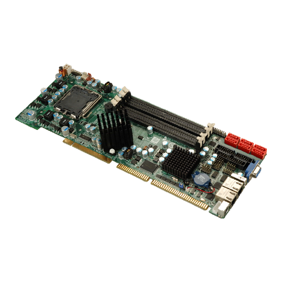
1.1 Overview Figure 1-1: WSB-Q354 PICMG 1.0 CPU Card The WSB-Q354 also comes with dual PCI Express (PCIe) Gigabit Ethernet (GbE) and has flexible storage options including support for six second-generation serial ATA (SATA) with SATA RAID configuration and a floppy disk drive (FDD). The WSB-Q354 provides additional connectivity for one parallel, two RS-232 serial and up to seven USB 2.0... -
Page 18: Wsb-Q354 Overview
Supports ATX power supplies 1.2 WSB-Q354 Overview 1.2.1 WSB-Q354 Overview Photo The WSB-Q354 has a wide variety of peripheral interface connectors. Figure 1-2 is a labeled photo of the peripheral interface connectors on the WSB-Q354. Figure 1-2: WSB-Q354 Overview [Front View] 1.2.2 WSB-Q354 Peripheral Connectors and Jumpers... -
Page 19: Technical Specifications
1 x USB 2.0 connectors 1 x VGA connector The WSB-Q354 has the following on-board jumpers: Clear CMOS 1.2.3 Technical Specifications WSB-Q354 technical specifications are listed in Table 1-1. See Chapter 2 for details. Specification WSB-Q354 PICMG 1.0 Form Factor LGA775 Intel®... - Page 20 WSB-Q354 PICMG 1.0 CPU Card Four 240-pin DDR2 DIMM sockets support 2.0 GB 667 MHz or Memory 800 MHz DDR2 DIMMs Super I/O ITE IT8718F Rev. I Display Analog VGA display through external DB-15 connector AMI BIOS label BIOS SPI EEPROM 8.0 MB...
-
Page 21: Table 1-1: Technical Specifications
WSB-Q354 PICMG 1.0 CPU Card Fan Connector 4-pin CPU fan connector Buzzer 5V@5.97A, +12V@0.29A , Vcore@2.97 and 5VSB@0.07A Power Consumption (Intel® Core™2 Duo E8500 CPU with four 2.0 GB, 800 MHz DDR2 DIMM running 3Dmark® 2001SE) Temperature 0ºC – 60ºC (32ºF - 140ºF) -
Page 22: Detailed Specifications
WSB-Q354 PICMG 1.0 CPU Card Chapter Detailed Specifications Page 7... -
Page 23: Dimensions
WSB-Q354 PICMG 1.0 CPU Card 2.1 Dimensions 2.1.1 Board Dimensions The dimensions of the board are listed below: Length: 338 mm Width: 126 mm Figure 2-1: WSB-Q354 Dimensions (mm) Page 8... -
Page 24: External Interface Panel Dimensions
WSB-Q354 PICMG 1.0 CPU Card 2.1.2 External Interface Panel Dimensions External peripheral interface connector panel dimensions are shown in Figure 2-2. Figure 2-2: External Interface Panel Dimensions (mm) Page 9... -
Page 25: Data Flow
WSB-Q354 PICMG 1.0 CPU Card 2.2 Data Flow Figure 2-3 shows the data flow between the two on-board chipsets and other components installed on the CPU card and described in the following sections of this chapter. Figure 2-3: Data Flow Block Diagram... -
Page 26: Compatible Processors
Intel® Celeron® (Conroe) 2.3.2 Supported Intel® Core™2 Quad (Yorkfield) Processors Table 2-3 lists the Yorkfield core Intel® Core™2 Quad processors supported on the WSB-Q354. All the processors in Table 2-3 are 45nm LGA775 processors. Processor # CPU Speed FSB Speed... -
Page 27: Supported Intel® Core™2 Duo (Conroe) Processors
WSB-Q354 PICMG 1.0 CPU Card 2.3.4 Supported Intel® Core™2 Duo (Conroe) Processors Table 2-3 lists the Conroe core Intel® Core™2 Duo processors supported on the WSB-Q354. All the processors in Table 2-3 are 65nm LGA775 processors with the following features: Enhanced Halt State (C1E) Enhance Intel®... -
Page 28: Intel® Q35 Northbridge Chipset
WSB-Q354 PICMG 1.0 CPU Card 2.4 Intel® Q35 Northbridge Chipset 2.4.1 Intel® Q35 Northbridge Chipset The Intel® Q35 Northbridge chipset is an advanced Graphics and Memory Controller Hub (GMCH) that supports a range of Intel® processors including 45nm Wolfdale dual core and Yorkfield quad core and 65nm Conroe core processors. -
Page 29: Intel® Q35 Memory Controller
The memory controller on the Intel® Q35 Northbridge can support up to 8.0 GB of DDR2 SDRAM. Four DDR2 SDRAM DIMM sockets on the WSB-Q354 are interfaced to the Intel® Q35 Northbridge memory controller. The DDR2 sockets are shown in Figure 2-5. -
Page 30: Intel® Q35 Analog Display Capability
WSB-Q354 PICMG 1.0 CPU Card 2.4.4 Intel® Q35 Analog Display Capability A single external female DB-15 (VGA) connector interfaces an analog display to an analog CRT port on the Intel® Q35 GMCH. The VGA connector is shown in Figure 2-6. -
Page 31: Intel ® Ich9R Southbridge Chipset
The Intel® ICH9R Southbridge chipset is connected to the Intel® Q35 GMCH through the chip-to-chip Direct Media Interface (DMI).The ICH9R Southbridge chipset on the WSB-Q354 has the features listed below. Complies with PCI Express Base Specification, Revision 1.1 Complies with PCI Local Bus Specification, Revision 2.3 and supports 33MHz... -
Page 32: Intel® Ich9R High Definition Audio Implementation
WSB-Q354 PICMG 1.0 CPU Card Interrupt controller Timer functions Integrated SATA host controller with DMA operations on six ports with data transfer rates up to 3.0 Gbps Supports seven USB 2.0 devices Complies with System Management Bus (SMBus) Specification, Version 2.0 ®... -
Page 33: Intel ® Ich9R Real Time Clock
WSB-Q354 PICMG 1.0 CPU Card ® 2.5.3 Intel ICH9R Real Time Clock 256 bytes of battery backed RAM is provided by the Motorola MC146818B real time clock (RTC) integrated into the ICH9R. The RTC operates on a 3V battery and 32.768KHz crystal. -
Page 34: Intel ® Ich9R Pci Interface
ICH9R USB Controller Overview Up to twelve high-speed, full-speed or low-speed USB devices are supported by the ICH9R on the WSB-Q354. High-speed USB 2.0, with data transfers of up to 480MB/s, is enabled with the ICH9R integrated Enhanced Host Controller Interface (EHCI) compliant... -
Page 35: Wsb-Q354 Usb Implementation
Universal Host Controller Interface (UHCI) controllers. 2.5.7.2 WSB-Q354 USB Implementation Seven of the Intel® ICH9R USB ports are implemented on the WSB-Q354. One USB port (USB Port 0) is connected to one external connector and six USB ports (USB Port 1 to USB Port 6) are connected to three 8-pin onboard pin-headers. -
Page 36: Winbond Pci-To-Isa Bridge Interface
WSB-Q354 PICMG 1.0 CPU Card Figure 2-10: PCI Slots 2.6.3 Winbond PCI-to-ISA Bridge Interface The Winbond PCI-to-ISA Bridge (Figure 2-11) enables legacy ISA expansion devices to be installed on the backplane and connected to the system through the ISA connector (Figure 2-11) on the bottom of the CPU card. -
Page 37: Lpc Bus Components
TPM module connector Super I/O chipset 2.7.2 TPM Module A TPM connector on the WSB-Q354 is interfaced to the Intel® ICH9R Southbridge through the LPC bus. The TPM connector is shown in Figure 2-12 below. Figure 2-12: TPM Connector The Intel® ICH9R Southbridge supports TPM version 1.1 and TPM version 1.2 devices for enhanced security. -
Page 38: Super I/O Chipset
WSB-Q354 PICMG 1.0 CPU Card 2.7.3 Super I/O chipset The ITE IT8718F Super I/O chipset is connected to the Intel® ICH9R Southbridge through the LPC bus. ITE IT8718F Super I/O chipset is shown in Figure 2-13 below. Figure 2-13: ITE IT8718F Super I/O The ITE IT8718F is an LPC interface-based Super I/O device that comes with an integrated Environment Controller. -
Page 39: Super I/O Lpc Interface
WSB-Q354 PICMG 1.0 CPU Card 2.7.3.1 Super I/O LPC Interface ® The LPC interface on the Super I/O complies with the Intel Low Pin Count Specification Rev. 1.0. The LPC interface supports both LDRQ# and SERIRQ protocols as well as PCI PME# interfaces. -
Page 40: Super I/O Fan Speed Controller
2.7.3.7 Super I/O GPIO Ports The Super I/O has 48 programmable GPIO ports of which 8 are implemented on the WSB-Q354. The GPIO connector has 8 programmable bits, 4-bit input and 4-bit output. 2.7.3.8 Super I/O Infrared The Super I/O has dedicated infrared (IrDA) pins that are interfaced to an IrDA connector. -
Page 41: Super I/O Watchdog Timer
The super I/O watchdog timer has a maximum time resolution of 1 minute or 1 second with a maximum or either 65,535 minutes or 65,535 seconds. 2.8 Environmental and Power Specifications 2.8.1 System Monitoring Three thermal inputs on the WSB-Q354 Super I/O Enhanced Hardware Monitor monitor the following temperatures: CPU Temperature System Temperature... -
Page 42: Operating Temperature And Temperature Control
WSB-Q354 PICMG 1.0 CPU Card 2.8.2 Operating Temperature and Temperature Control The maximum and minimum operating temperatures for the WSB-Q354 are listed below. Minimum Operating Temperature: 0ºC (32°F) Maximum Operating Temperature: 60°C (140°F) A cooling fan and heat sink must be installed on the CPU. Thermal paste must be smeared on the lower side of the heat sink before it is mounted on the CPU. -
Page 43: Unpacking
WSB-Q354 PICMG 1.0 CPU Card Chapter Unpacking Page 28... -
Page 44: Anti-Static Precautions
When the WSB-Q354 is unpacked, please do the following: Follow the anti-static precautions outlined in Section 3.1. Make sure the packing box is facing upwards so the WSB-Q354 does not fall out of the box. Make sure all the components shown in Section 3.3 are present. -
Page 45: Unpacking Checklist
If some of the components listed in the checklist below are missing, please do not proceed with the installation. Contact the IEI reseller or vendor you purchased the WSB-Q354 from or contact an IEI sales representative directly. To contact an IEI sales representative, please send an email to sales@iei.com.tw. -
Page 46: Optional Items
WSB-Q354 PICMG 1.0 CPU Card SATA power cables (P/N: 32102-000100-200-RS) USB cable (P/N: 19800-003100-200-RS) Mini jumper Pack Quick Installation Guide Utility CD Table 3-1: Package List Contents 3.4 Optional Items 7.1 channel HD audio kit with Realtek ALC888 supports dual audio streams... -
Page 47: Table 3-2: Package List Contents
WSB-Q354 PICMG 1.0 CPU Card CPU cooling kit (P/N: CF-775A-RS) Infineon TPM module (P/N: TPM-IN01-R11) Table 3-2: Package List Contents Page 32... -
Page 48: Connector Pinouts
WSB-Q354 PICMG 1.0 CPU Card Chapter Connector Pinouts Page 33... -
Page 49: Peripheral Interface Connectors
Figure 4-1 shows the on-board peripheral connectors, rear panel peripheral connectors and on-board jumpers. Figure 4-1: Connector and Jumper Locations 4.1.2 Peripheral Interface Connectors Table 4-1 shows a list of the peripheral interface connectors on the WSB-Q354. Detailed descriptions of these connectors can be found below. Connector Type... -
Page 50: Table 4-1: Peripheral Interface Connectors
WSB-Q354 PICMG 1.0 CPU Card CPU power connector 4-pin wafer CPU12V1 Digital input/output connector 10-pin header DIO1 DIMM socket 240-pin socket DIMM1 DIMM socket 240-pin socket DIMM2 DIMM socket 240-pin socket DIMM3 DIMM socket 240-pin socket DIMM4 Floppy drive connector... -
Page 51: External Interface Panel Connectors
WSB-Q354 PICMG 1.0 CPU Card 4.1.3 External Interface Panel Connectors Table 4-2 lists the rear panel connectors on the WSB-Q354. Detailed descriptions of these connectors can be found in Section 4.3. Connector Type Label Ethernet connector RJ-45 LAN1 Ethernet connector... -
Page 52: Backplane Power Connector
WSB-Q354 PICMG 1.0 CPU Card Figure 4-2: Audio Connector Pinouts (4-pin) PIN NO. DESCRIPTION PIN NO. DESCRIPTION ACZ_SYNC ACZ_BITCLK ACZ_SDOUT ACZ_PCBEEP ACZ_SDIN ACZ_RST# ACZ_VCC ACZ_GND ACZ_12V ACZ_GND Table 4-3: Audio Connector Pinouts 4.2.2 Backplane Power Connector CN Label: ATXCTL1 CN Type:... -
Page 53: Cpu Power Connector
WSB-Q354 PICMG 1.0 CPU Card Figure 4-3: Backplane Power Connector Location PIN NO. DESCRIPTION PS_ON +5V Dual Table 4-4: Backplane Power Connector Pinouts 4.2.3 CPU Power Connector CN Label: CPU12V1 CN Type: 4-pin power connector (1x4) CN Location: See Figure 4-4... -
Page 54: Digital Input/Output (Dio) Connector
WSB-Q354 PICMG 1.0 CPU Card Figure 4-4: CPU Power Connector Location PIN NO. DESCRIPTION +12V +12V Table 4-5: CPU Power Connector Pinouts 4.2.4 Digital Input/Output (DIO) Connector CN Label: DIO1 CN Type: 10-pin header (2x5) CN Location: See Figure 4-5... -
Page 55: Fan Connector, Cpu (12V, 4-Pin)
WSB-Q354 PICMG 1.0 CPU Card Figure 4-5: DIO Connector Location PIN NO. DESCRIPTION PIN NO. DESCRIPTION Ground Output 3 Output 2 Output 1 Output 0 Input 3 Input 2 Input 1 Input 0 Table 4-6: DIO Connector Pinouts 4.2.5 Fan Connector, CPU (12V, 4-pin) -
Page 56: Floppy Disk Connector (34-Pin)
WSB-Q354 PICMG 1.0 CPU Card Figure 4-6: +12V Fan Connector Location PIN NO. DESCRIPTION +12VCC Rotation Signal Control Table 4-7: +12V Fan Connector Pinouts 4.2.6 Floppy Disk Connector (34-pin) CN Label: FDD1 CN Type: 34-pin box header (2x17) CN Location:... -
Page 57: Figure 4-7: 34-Pin Fdd Connector Location
WSB-Q354 PICMG 1.0 CPU Card Figure 4-7: 34-pin FDD Connector Location PIN NO. DESCRIPTION PIN NO. DESCRIPTION Density Select# INDEX# MOTOR ENABLE A# DRIVE ENABLE B# DRIVE ENABLE A# MOTOR ENABLE B# DIRECTION# STEP# WRITE DATA# WRITE GATE# TRACK 0#... -
Page 58: Front Panel Connector
WSB-Q354 PICMG 1.0 CPU Card 4.2.7 Front Panel Connector CN Label: F_PANEL1 CN Type: 14-pin header (2x7) CN Location: See Figure 4-8 CN Pinouts: See Table 4-9 The front panel connector connects to external switches and indicators to monitor and controls the CPU card. -
Page 59: Infrared Interface Connector
WSB-Q354 PICMG 1.0 CPU Card IDE LED- GROUND Table 4-9: Front Panel Connector Pinouts (14-pin) 4.2.8 Infrared Interface Connector CN Label: CN Type: 5-pin header (1x5) CN Location: See Figure 4-9 CN Pinouts: See Table 4-10 The infrared interface connector supports both Serial Infrared (SIR) and Amplitude Shift Key Infrared (ASKIR) interfaces. -
Page 60: Keyboard Connector
WSB-Q354 PICMG 1.0 CPU Card 4.2.9 Keyboard Connector CN Label: CN Type: 5-pin wafer (1x5) CN Location: See Figure 4-10 CN Pinouts: See Table 4-11 The keyboard connector can be connected to a standard PS/2 cable or PS/2 cable to add keyboard and mouse functionality to the system. -
Page 61: Figure 4-11: Parallel Port Connector Location
WSB-Q354 PICMG 1.0 CPU Card CN Location: See Figure 4-11 CN Pinouts: See Table 4-12 The 26-pin parallel port connector connects to a parallel port connector interface or some other parallel port device such as a printer. Figure 4-11: Parallel Port Connector Location PIN NO. -
Page 62: Sata Drive Connectors
WSB-Q354 PICMG 1.0 CPU Card 4.2.11 SATA Drive Connectors CN Label: SATA1, SATA2, SATA3, SATA4, SATA5 and SATA6 CN Type: 7-pin SATA drive connectors (1x7) CN Location: See Figure 4-12 CN Pinouts: See Table 4-13 The six SATA drive connectors are each connected to second generation SATA drives. -
Page 63: Serial Port Connector (Com 1 And Com2)
WSB-Q354 PICMG 1.0 CPU Card 4.2.12 Serial Port Connector (COM 1 and COM2) CN Label: COM1 and COM2 CN Type: 10-pin header (2x5) CN Location: See Figure 4-13 CN Pinouts: See Table 4-14 The 10-pin serial port connector provides a second RS-232 serial communications channel. -
Page 64: Spi Flash Connector (Optional)
WSB-Q354 PICMG 1.0 CPU Card 4.2.13 SPI Flash Connector (Optional) CN Label: JSPI1 CN Type: 8-pin header (2x4) CN Location: See Figure 4-14 CN Pinouts: See Table 4-15 The 8-pin SPI Flash connector is used to flash the BIOS. The JSPI1 connector is an optional connector. -
Page 65: Usb Connectors (Internal)
WSB-Q354 PICMG 1.0 CPU Card CN Pinouts: See Table 4-16 The Trusted Platform Module (TPM) connector secures the system on bootup. An optional TPM (see packing list in Chapter 3) can be connected to the TPM connector. Figure 4-15: TPM Connector Location PIN NO. -
Page 66: External Peripheral Interface Connector Panel
DATA- Table 4-17: USB Port Connector Pinouts 4.3 External Peripheral Interface Connector Panel Figure 4-17 shows the WSB-Q354 external peripheral interface connector (EPIC) panel. The WSB-Q354 EPIC panel consists of the following: 1 x PS/2 keyboard/mouse connector 2 x RJ-45 LAN connectors 1 x USB 2.0 ports... -
Page 67: Keyboard/Mouse Connector
CN Label: KB_MS1 PS/2 CN Type: CN Location: See Figure 4-17 CN Pinouts: See Figure 4-18 and Table 4-18 The WSB-Q354 keyboard and mouse connector is a standard PS/2 connector. Figure 4-18: PS/2 Pinouts DESCRIPTION K_DAT M_DAT VCC5 K_CLK M_CLK... -
Page 68: Lan And Dual Usb Combo Connectors
CN Pinouts: See Table 4-19 The WSB-Q354 is equipped with two built-in RJ-45 Ethernet controllers. The controllers can connect to the LAN through two RJ-45 LAN connectors. There are two LEDs on the connector indicating the status of LAN. The pin assignments are listed in the following... -
Page 69: Usb Connector
USB port CN Location: See Figure 4-17 CN Pinouts: See Table 4-21 The WSB-Q354 has one external USB 2.0 ports. The port connects to both USB 2.0 and USB 1.1 devices. PIN NO. DESCRIPTION DATA- DATA+ Table 4-21: USB Port Pinouts 4.3.4 VGA Connector... -
Page 70: Figure 4-20: Vga Connector
WSB-Q354 PICMG 1.0 CPU Card Figure 4-20: VGA Connector DESCRIPTION DESCRIPTION GREEN BLUE VCC / NC DDC DAT HSYNC VSYNC DDCCLK Table 4-22: VGA Connector Pinouts Page 55... -
Page 71: Installation
WSB-Q354 PICMG 1.0 CPU Card Chapter Installation Page 56... -
Page 72: Anti-Static Precautions
Electrostatic discharge (ESD) can cause serious damage to electronic components, including the WSB-Q354. Dry climates are especially susceptible to ESD. It is therefore critical that whenever the WSB-Q354, or any other electrical component is handled, the following anti-static precautions are strictly adhered to. -
Page 73: Installation Considerations
WSB-Q354 should be strictly adhered to. Failing to adhere to these precautions may lead to severe damage of the WSB-Q354 and injury to the person installing the CPU card. 5.2.1 Installation Notices... -
Page 74: Installation Checklist
Allow screws to come in contact with the PCB circuit, connector pins, or its components. 5.2.2 Installation Checklist The following checklist is provided to ensure the WSB-Q354 is properly installed. All the items in the packing list are present The CPU is installed... -
Page 75: Unpacking
Running a CPU without a cooling kit may also result in injury to the user. The CPU, CPU cooling kit and DIMM are the most critical components of the WSB-Q354. If one of these components is not installed the WSB-Q354 cannot run. -
Page 76: Socket Lga775 Cpu Installation
The LGA775 socket is shown in Figure 5-1. Figure 5-1: Intel® LGA775 Socket To install a socket LGA775 CPU onto the WSB-Q354, follow the steps below: Page 61... -
Page 77: Figure 5-2: Remove The Cpu Socket Protective Shield
WSB-Q354 PICMG 1.0 CPU Card WARNING: When handling the CPU, only hold it on the sides. DO NOT touch the pins at the bottom of the CPU. Step 1: Remove the protective cover. Remove the black protective cover by prying it off the load plate. -
Page 78: Figure 5-3: Open The Cpu Socket Load Plate
WSB-Q354 PICMG 1.0 CPU Card Figure 5-3: Open the CPU Socket Load Plate Step 3: Inspect the CPU socket Make sure there are no bent pins and make sure the socket contacts are free of foreign material. If any debris is found, remove it with compressed air. -
Page 79: Socket Lga775 Cf-520 Cooling Kit Installation
WARNING: It is strongly recommended that you DO NOT use the original heat sink and cooler provided by Intel® on the WSB-Q354. IEI’s cooling kit (CF-520) includes a support bracket that is combined with the heat sink mounted on the CPU to counterweigh and balance the load on both sides of the PCB. -
Page 80: Figure 5-5: Iei Cf-520 Cooling Kit
WSB-Q354 PICMG 1.0 CPU Card Figure 5-5: IEI CF-520 Cooling Kit An IEI Socket LGA775 CPU cooling kit shown in Figure 5-5 can be purchased separately. The cooling kit comprises a CPU heat sink and a cooling fan. WARNING: Do not wipe off (accidentally or otherwise) the pre-sprayed layer of thermal paste on the bottom of the CF-520 heat sink. -
Page 81: Dimm Installation
Step 6: Connect the fan cable. Connect the cooling kit fan cable to the fan connector on the WSB-Q354. Carefully route the cable and avoid heat generating chips and fan blades. Step 0: 5.4.3 DIMM Installation... -
Page 82: Dimm Purchasing Guidelines
Channel B. DDR2 Channel A and DDR2 Channel B are shown in Figure 5-7 below. Figure 5-7: DDR2 Channels On the WSB-Q354, each channel is interfaced to two 240-pin DIMM sockets in the following order (see Figure 5-7 above): Channel A: DIMM1 and DIMM2... -
Page 83: Dimm Installation Guidelines
WSB-Q354 PICMG 1.0 CPU Card Channel B: DIMM3 and DIMM4 When populating the DDR2 DIMM sockets, populate them in the following order to optimize the memory performance: Step 1: DIMM1. Install the first DDR2 DIMM into the DIMM1 DDR2 DIMM socket. -
Page 84: Jumper Settings
WSB-Q354 PICMG 1.0 CPU Card Figure 5-8: Installing a DIMM Step 3: Insert the DIMM. Once properly aligned, the DIMM can be inserted into the socket. As the DIMM is inserted, the white handles on the side of the socket will close automatically and secure the DIMM to the socket. -
Page 85: Clear Cmos Jumper
WSB-Q354 PICMG 1.0 CPU Card Before the WSB-Q354 is installed in the system, the jumpers must be set in accordance with the desired configuration. The jumper on the WSB-Q354 is listed in Table 5-1. Description Label Type Clear CMOS J_CMOS1... -
Page 86: Chassis Installation
The WSB-Q354 must be installed in a chassis with ventilation holes on the sides allowing airflow to travel through the heat sink surface. In a system with an individual power supply unit, the cooling fan of a power supply can also help generate airflow through the board surface. -
Page 87: Cpu Card Installation
WSB-Q354 PICMG 1.0 CPU Card 5.6.2 CPU Card Installation To install the WSB-Q354 CPU card onto the backplane, carefully align the CPU card interface connectors with the corresponding socket on the backplane. To do this, please refer to the reference material that came with the backplane. Next, secure the CPU card to the chassis. -
Page 88: Sata Drive Connection
0: 5.7.3 SATA Drive Connection The WSB-Q354 is shipped with two SATA drive cables and one SATA drive power cable. To connect the SATA drives to the connectors, please follow the steps below. Page 73... -
Page 89: Figure 5-11: Sata Drive Cable Connection
WSB-Q354 PICMG 1.0 CPU Card Step 1: Locate the connectors. The locations of the SATA drive connectors are shown in Chapter 3. Step 2: Insert the cable connector. Press the clip on the connector at the end of the SATA cable and insert the cable connector into the onboard SATA drive connector. -
Page 90: Usb Cable (Dual Port)
WSB-Q354 PICMG 1.0 CPU Card Figure 5-12: SATA Power Drive Connection 5.7.4 USB Cable (Dual Port) The WSB-Q354 is shipped with a dual port USB 2.0 cable. To connect the USB cable connector, please follow the steps below. Step 1: Locate the connectors. -
Page 91: Channel Audio Kit Installation
The optional 7.1 channel audio kit connects to the 10-pin audio connector on the WSB-Q354. The audio kit consists of five audio jacks. One audio jack, Mic In, connects to a microphone. The remaining four audio jacks, Line-In, Front-Out, Rear-Out, and Center Subwoofer, connect to speakers. -
Page 92: Figure 5-14: 7.1 Channel Audio Kit
Step 4: Mount the audio kit onto the chassis. Once the audio kit is connected to the WSB-Q354, secure the audio kit bracket to the system chassis. Step 5: Connect the audio devices. Connect one speaker to the line-in audio jack, one speaker to the line-out audio jack and a microphone to the mic-in audio jack. -
Page 93: External Peripheral Interface Connection
USB devices VGA monitors To install these devices, connect the corresponding cable connector from the actual device to the corresponding WSB-Q354 external peripheral interface connector making sure the pins are properly aligned. 5.8.1 LAN Connection (Single Connector) There are two external RJ-45 LAN connectors. The RJ-45 connectors enable connection to an external network. -
Page 94: Ps/2 Keyboard And Mouse Connection
Step 0: 5.8.2 PS/2 Keyboard and Mouse Connection The WSB-Q354 has a single PS/2 connector on the external peripheral interface panel. The PS/2 connector is used to connect to a keyboard and mouse to the system. Follow the steps below to connect a keyboard and mouse to the WSB-Q354. -
Page 95: Usb Device Connection
Figure 5-16: PS/2 Keyboard/Mouse Connector 5.8.3 USB Device Connection There is one external USB 2.0 connector. The USB connector is perpendicular to the WSB-Q354. To connect a USB 2.0 or USB 1.1 device, please follow the instructions below. Step 1: Located the USB connector. -
Page 96: Vga Monitor Connection
Step 0: 5.8.4 VGA Monitor Connection The WSB-Q354 has a single female DB-15 connector on the external peripheral interface panel. The DB-15 connector is connected to a CRT or VGA monitor. To connect a monitor to the WSB-Q354, please follow the instructions below. -
Page 97: Figure 5-18: Vga Connector
WSB-Q354 PICMG 1.0 CPU Card Figure 5-18: VGA Connector Step 4: Secure the connector. Secure the DB-15 VGA connector from the VGA monitor to the external interface by tightening the two retention screws on either side of the connector. Step 0:... -
Page 98: Ami Bios
WSB-Q354 PICMG 1.0 CPU Card Chapter AMI BIOS Page 83... -
Page 99: Introduction
WSB-Q354 PICMG 1.0 CPU Card 6.1 Introduction A licensed copy of AMI BIOS is preprogrammed into the ROM BIOS. The BIOS setup program allows users to modify the basic system configuration. This chapter describes how to access the BIOS setup program and the configuration options that may be changed. -
Page 100: Getting Help
WSB-Q354 PICMG 1.0 CPU Card F1 key General help, only for Status Page Setup Menu and Option Page Setup Menu F2 /F3 key Change color from total three colors. F2 to select color forward. F10 key Save all the CMOS changes, only for Main Menu Table 6-1: BIOS Navigation Keys 6.1.3 Getting Help... -
Page 101: Main
WSB-Q354 PICMG 1.0 CPU Card 6.2 Main The Main BIOS menu (BIOS Menu 1) appears when the BIOS Setup program is entered. The Main menu gives an overview of the basic system information. BIOS Menu 1: Main System Overview The System Overview lists a brief summary of different system components. The fields in System Overview cannot be changed. -
Page 102: Advanced
WSB-Q354 PICMG 1.0 CPU Card System Memory: Displays the auto-detected system memory. Size: Lists memory size The System Overview field also has two user configurable fields: System Time [xx:xx:xx] Use the System Time option to set the system time. Manually enter the hours, minutes and seconds. -
Page 103: Cpu Configuration
WSB-Q354 PICMG 1.0 CPU Card BIOS Menu 2: Advanced 6.3.1 CPU Configuration Use the CPU Configuration menu (BIOS Menu 3) to view detailed CPU specifications and configure the CPU. Page 88... -
Page 104: Ide Configuration
WSB-Q354 PICMG 1.0 CPU Card BIOS Menu 3: CPU Configuration The CPU Configuration menu (BIOS Menu 3) lists the following CPU details: Manufacturer: Lists the name of the CPU manufacturer Brand String: Lists the brand name of the CPU being used... -
Page 105: Menu 4: Ide Configuration
WSB-Q354 PICMG 1.0 CPU Card BIOS Menu 4: IDE Configuration SATA#n Configuration [Enhanced] Use the SATA#n BIOS option to enable the n SATA drive port. Disabled The n SATA drive port is disabled Enhanced The n SATA drive port is activated... -
Page 106: Ide Master, Ide Slave
WSB-Q354 PICMG 1.0 CPU Card IDE Master and IDE Slave When entering setup, BIOS auto detects the presence of IDE devices. BIOS displays the status of the auto detected IDE devices. The following IDE devices are detected and are shown in the IDE Configuration menu:... -
Page 107: Menu 5: Ide Master And Ide Slave Configuration
WSB-Q354 PICMG 1.0 CPU Card BIOS Menu 5: IDE Master and IDE Slave Configuration Auto-Detected Drive Parameters The “grayed-out” items in the left frame are IDE disk drive parameters automatically detected from the firmware of the selected IDE disk drive. The drive parameters are listed as follows: Device: Lists the device type (e.g. - Page 108 WSB-Q354 PICMG 1.0 CPU Card Async DMA: Indicates the highest Asynchronous DMA Mode that is supported. Ultra DMA: Indicates the highest Synchronous DMA Mode that is supported. S.M.A.R.T.: Indicates whether or not the Self-Monitoring Analysis and Reporting Technology protocol is supported.
- Page 109 WSB-Q354 PICMG 1.0 CPU Card Disabled BIOS is prevented from using the LBA mode control on the specified channel. BIOS auto detects the LBA mode control on the specified Auto EFAULT channel. Block (Multi Sector Transfer) [Auto] Use the Block (Multi Sector Transfer) to disable or enable BIOS to auto detect if the device supports multi-sector transfers.
- Page 110 WSB-Q354 PICMG 1.0 CPU Card CD-ROM drives, check the specifications of the drive.) DMA Mode [Auto] Use the DMA Mode BIOS selection to adjust the DMA mode options. Auto BIOS auto detects the DMA mode. Use this value if the IDE EFAULT disk drive support cannot be determined.
-
Page 111: Floppy Configuration
WSB-Q354 PICMG 1.0 CPU Card 80-conductor ATA cable is used.) UDMA5 Ultra DMA mode 5 selected with a maximum data transfer rate of 99.9MBps (To use this mode, it is required that an 80-conductor ATA cable is used.) S.M.A.R.T [Auto] Use the S.M.A.R.T option to auto-detect, disable or enable Self-Monitoring Analysis and... -
Page 112: Super Io Configuration
WSB-Q354 PICMG 1.0 CPU Card BIOS Menu 6: IDE Master and IDE Slave Configuration Floppy A Use the Floppy A option to configure the floppy disk drive. Options are listed below: Disabled 1.44 MB 31/2” 6.3.4 Super IO Configuration Use the Super IO Configuration menu (BIOS Menu 7) to set or change the configurations for the FDD controllers, parallel ports and serial ports. -
Page 113: Menu 7: Super Io Configuration
WSB-Q354 PICMG 1.0 CPU Card BIOS Menu 7: Super IO Configuration Serial Port1 Address [3F8/IRQ4] Use the Serial Port1 Address option to select the Serial Port 1 base address. Disabled No base address is assigned to Serial Port 1 3F8/IRQ4... - Page 114 WSB-Q354 PICMG 1.0 CPU Card Normal Serial Port 1 mode is normal EFAULT Serial Port 1 mode is IrDA IrDA ASK IR Serial Port 1 mode is ASK IR Serial Port2 Address [2F8/IRQ3] Use the Serial Port2 Address option to select the Serial Port 2 base address.
- Page 115 WSB-Q354 PICMG 1.0 CPU Card Parallel Port Mode [Normal] Use the Parallel Port Mode option to select the mode the parallel port operates in. The normal parallel port mode is the standard mode Normal EFAULT for parallel port operation. The parallel port operates in the enhanced parallel port mode (EPP).
-
Page 116: Hardware Health Configuration
WSB-Q354 PICMG 1.0 CPU Card 6.3.5 Hardware Health Configuration The Hardware Health Configuration menu (BIOS Menu 8) shows the operating temperature, fan speeds and system voltages. BIOS Menu 8: Hardware Health Configuration FAN 1 Mode Setting [Full On Mode] Use the FAN 1 Mode Setting option to configure the second fan. -
Page 117: Acpi Configuration
WSB-Q354 PICMG 1.0 CPU Card The following system parameters and values are shown. The system parameters that are monitored are: System Temperatures: The following system temperatures are monitored CPU Temperature System Temperature Fan Speeds: The CPU cooling fan speed is monitored. -
Page 118: Menu 9: Acpi Configuration
WSB-Q354 PICMG 1.0 CPU Card BIOS Menu 9: ACPI Configuration Suspend Mode [S1(POS)] Use the Suspend Mode option to specify the sleep state the system enters when it is not being used. S1 (POS) The system enters S1(POS) sleep state. The system EFAULT appears off. -
Page 119: Ahci Configuration
WSB-Q354 PICMG 1.0 CPU Card 6.3.7 AHCI Configuration NOTE: Advanced Host Controller Interface (AHCI) is a new programming interface for SATA host controllers. AHCI systems do not have master/slave designation for SATA devices, each device is treated as a master, and hardware-assisted native command queuing. -
Page 120: Ahci Port N
WSB-Q354 PICMG 1.0 CPU Card AHCI Port n [Not Detected] Use the AHCI Port n BIOS option to check what AHCI (Advanced Host Controller Interface) devices are detected to a specified SATA drive connector. If a device is detected, selecting the BIOS option, e.g. “AHCI Port 3” opens a new window. -
Page 121: Remote Access Configuration
WSB-Q354 PICMG 1.0 CPU Card S.M.A.R.T [Enabled] Use the S.M.A.R.T option to enable S.M.A.R.T (Self-Monitoring, Analysis, and Reporting Technology) on the drive connected to SATA drive connector n. Enabled S.M.A.R.T is enabled on the drive connected to SATA EFAULT drive connector n on the system S.M.A.R.T is disabled on the drive connected to SATA... - Page 122 WSB-Q354 PICMG 1.0 CPU Card Remote Access [Disabled] Use the Remote Access option to enable or disable access to the remote functionalities of the system. Disabled Remote access is disabled. EFAULT Remote access configuration options shown below Enabled appear: Serial Port Number...
-
Page 123: Trusted Computing
WSB-Q354 PICMG 1.0 CPU Card 115200 8,n,1 D EFAULT 57600 8,n,1 38400 8,n,1 19200 8,n,1 09600 8,n,1 NOTE: Identical baud rate setting musts be set on the host (a management computer running a terminal software) and the slave Redirection After BIOS POST [Always] Use the Redirection After BIOS POST option to specify when console redirection should occur. -
Page 124: Usb Configuration
WSB-Q354 PICMG 1.0 CPU Card BIOS Menu 13: Trusted Computing TCG/TPM Support [No] Use the TCG/TPM Support option to configure support for the TPM. TPM support is disabled. EFAULT TPM support is enabled. 6.3.10 USB Configuration Use the USB Configuration menu (BIOS Menu 14) to read USB configuration information and configure the USB settings. -
Page 125: Menu 14: Usb Configuration
WSB-Q354 PICMG 1.0 CPU Card BIOS Menu 14: USB Configuration USB Configuration The USB Configuration field shows the system USB configuration. The items listed are: Module Version: x.xxxxx.xxxxx USB Devices Enabled The USB Devices Enabled field lists the USB devices that are enabled on the system USB Function [Enabled] Use the USB Function BIOS option to enable or disable USB function support. -
Page 126: Pci/Pnp
WSB-Q354 PICMG 1.0 CPU Card USB 2.0 Controller [Enabled] Use the USB 2.0 Controller BIOS option to enable or disable the USB 2.0 controller USB 2.0 controller disabled Disabled Enabled USB 2.0 controller enabled EFAULT Legacy USB Support [Enabled] Use the Legacy USB Support BIOS option to enable USB mouse and USB keyboard support. -
Page 127: Menu 15: Pci/Pnp Configuration
WSB-Q354 PICMG 1.0 CPU Card may cause the system to malfunction. BIOS Menu 15: PCI/PnP Configuration IRQ# [Available] Use the IRQ# address to specify what IRQs can be assigned to a particular peripheral device. The specified IRQ is available to be used by... - Page 128 WSB-Q354 PICMG 1.0 CPU Card IRQ7 IRQ9 IRQ10 IRQ 11 IRQ 14 IRQ 15 DMA Channel# [Available] Use the DMA Channel# option to assign a specific DMA channel to a particular PCI/PnP device. Available The specified DMA is available to be used by...
-
Page 129: Boot
WSB-Q354 PICMG 1.0 CPU Card 6.5 Boot Use the Boot menu (BIOS Menu 16) to configure system boot options. BIOS Menu 16: Boot 6.5.1 Boot Settings Configuration Use the Boot Settings Configuration menu (BIOS Menu 17) to configure advanced system boot options. -
Page 130: Menu 17: Boot Settings Configuration
WSB-Q354 PICMG 1.0 CPU Card BIOS Menu 17: Boot Settings Configuration Quick Boot [Enabled] Use the Quick Boot BIOS option to make the computer speed up the boot process. Disabled No POST procedures are skipped Enabled Some POST procedures are skipped to decrease... - Page 131 WSB-Q354 PICMG 1.0 CPU Card AddOn ROM Display Mode [Force BIOS] Use the AddOn ROM Display Mode option to allow add-on ROM (read-only memory) messages to be displayed. Force BIOS The system forces third party BIOS to display EFAULT during system boot.
-
Page 132: Boot Device Priority
WSB-Q354 PICMG 1.0 CPU Card 6.5.2 Boot Device Priority Use the Boot Device Priority menu (BIOS Menu 18) to specify the boot sequence from the available devices. Possible boot devices may include: FLOPPY DRIVE CD/DVD BIOS Menu 18: Boot Device Priority Settings 6.5.3 Removable Drives... -
Page 133: Security
WSB-Q354 PICMG 1.0 CPU Card one FDD is connected only “1st Drive” is listed. The boot sequence from the available devices is selected. If the “1st Drive” option is selected a list of available FDDs is shown. Select the first FDD the system boots from. If the “1st Drive”... -
Page 134: Chipset
WSB-Q354 PICMG 1.0 CPU Card Change User Password Use the Change User Password to set or change a user password. The default for this option is Not Installed. If a user password must be installed, select this field and enter the password. -
Page 135: Northbridge Configuration
WSB-Q354 PICMG 1.0 CPU Card BIOS Menu 20: Chipset 6.7.1 NorthBridge Configuration Use the Northbridge Chipset Configuration menu (BIOS Menu 21) to configure the Northbridge chipset. Page 120... -
Page 136: Menu 21:Northbridge Chipset Configuration
WSB-Q354 PICMG 1.0 CPU Card BIOS Menu 21:Northbridge Chipset Configuration Memory Remap Feature [Enabled] Use the Memory Remap Feature option to allow the overlapped PCI memory above the total physical memory to be remapped. Enabled Overlapped PCI memory can be remapped... -
Page 137: Southbridge Configuration
WSB-Q354 PICMG 1.0 CPU Card ISA expansion cards Initiate Graphic Adapter [PCI/IGD] Use the Initiate Graphic Adapter option to select the graphics controller used as the primary boot device. Select either an integrated graphics controller (IGD) or a combination of PCI graphics controller, a PCI express (PEG) controller or an IGD. Configuration... -
Page 138: Menu 22:Southbridge Chipset Configuration
WSB-Q354 PICMG 1.0 CPU Card BIOS Menu 22:Southbridge Chipset Configuration ASF Support [Enabled] Use the ASF Support BIOS option to control the system’s ability to connect to a remote management server. Enabled The Alert Standard Format (ASF) controller is activated... -
Page 139: Exit
WSB-Q354 PICMG 1.0 CPU Card Restore on AC Power Loss [Last State] Use the Restore on AC Power Loss BIOS option to specify what state the system returns to if there is a sudden loss of power to the system. - Page 140 WSB-Q354 PICMG 1.0 CPU Card Discard Changes and Exit Use the Discard Changes and Exit option to exit the BIOS configuration setup program without saving the changes made to the system. Discard Changes Use the Discard Changes option to discard the changes and remain in the BIOS configuration setup program.
-
Page 141: Software Drivers
WSB-Q354 PICMG 1.0 CPU Card Chapter Software Drivers Page 126... -
Page 142: Available Software Drivers
Audio driver Installation instructions are given below. 7.2 Driver CD Auto-run All the drivers for the WSB-Q354 are on the CD that came with the system. To install the drivers, please follow the steps below. Step 1: Insert the CD into a CD drive connected to the system. -
Page 143: Figure 7-1: Introduction Screen
WSB-Q354 PICMG 1.0 CPU Card Figure 7-1: Introduction Screen Step 3: Click WSB-Q354. Step 4: A new screen with a list of available drivers appears (Figure 7-2). Figure 7-2: Available Drivers Step 5: Select the driver to install from the list in Figure 7-2. Detailed driver installation instructions follow below. -
Page 144: Intel® Chipset Driver
WSB-Q354 PICMG 1.0 CPU Card 7.3 Intel® Chipset Driver To install the Intel® chipset driver, please follow the steps below. Step 1: Select WSB-Q354 from the list in Figure 7-1. Select INF from the list in Figure 7-2. Step 2: Step 3: The window shown in Figure 7-3 appears. -
Page 145: Figure 7-4: Intel® Chipset Driver Setup Icon
WSB-Q354 PICMG 1.0 CPU Card Figure 7-4: Intel® Chipset Driver Setup Icon Step 6: Click on the infinst_autol setup icon in Figure 7-4. Step 7: The Intel® Package Manager begins to extract the installation files. See Figure 7-5. Page 130... -
Page 146: Figure 7-5: Intel® Package Manager
WSB-Q354 PICMG 1.0 CPU Card Figure 7-5: Intel® Package Manager Step 8: The Intel® Setup Welcome screen. See Figure 7-6. Figure 7-6: Intel® Setup Welcome Screen Step 9: Click N to continue. Step 10: The Intel® license agreement in appears. -
Page 147: Figure 7-7: Intel® Chipset Driver License Agreement
WSB-Q354 PICMG 1.0 CPU Card Figure 7-7: Intel® Chipset Driver License Agreement Step 11: Accept the terms and conditions by clicking Y Step 12: The Readme file in Figure 7-8 appears. Figure 7-8: Readme File Step 13: Click N to continue. -
Page 148: Intel® Graphics Media Accelerator Driver
WSB-Q354 PICMG 1.0 CPU Card Figure 7-9: Intel® Chipset Driver Complete Installation Screen Step 16: To complete the chipset driver installation, click F Step 0: INISH 7.4 Intel® Graphics Media Accelerator Driver To install the chipset driver, please follow the steps below: Step 1: Select the VGA driver from the list in Figure 7-2. -
Page 149: Figure 7-10: Select The Operating System
WSB-Q354 PICMG 1.0 CPU Card Figure 7-10: Select the Operating System Step 3: Select the operating system from those shown in Figure 7-10. Step 4: A new window appears. See Figure 7-11. Figure 7-11: Intel® Driver Directory Page 134... -
Page 150: Figure 7-12: Intel® Vga Driver Setup Icon
WSB-Q354 PICMG 1.0 CPU Card Step 5: Click the directory icon in Figure 7-11. Step 6: A new window appears. See Figure 7-12. Figure 7-12: Intel® VGA Driver Setup Icon Step 7: Click on the VGA driver installation icon in See Figure 7-12. -
Page 151: Figure 7-13: Gma Driver Readme File
WSB-Q354 PICMG 1.0 CPU Card Figure 7-13: GMA Driver Readme File Step 9: Click N to extract the GMA driver files. See Figure 7-14. Figure 7-14: GMA Driver File Extraction Step 10: The welcome screen shown in Figure 7-15 appears. -
Page 152: Figure 7-16: Gma Driver License Agreement
WSB-Q354 PICMG 1.0 CPU Card Step 12: The license agreement in Figure 7-16 appears. Figure 7-16: GMA Driver License Agreement Step 13: Click the Y in Figure 7-16 to continue. Step 14: The installation notice shown in Figure 7-17 appears. -
Page 153: Realtek Lan Driver (For Gbe Lan) Installation
WSB-Q354 PICMG 1.0 CPU Card Figure 7-18: GMA Driver Installation Complete Step 16: After selecting when to restart the computer in Figure 7-18, click F INISH 7.5 Realtek LAN Driver (for GbE LAN) Installation To install the Realtek LAN driver, please follow the steps below. -
Page 154: Figure 7-19: Windows Control Panel
WSB-Q354 PICMG 1.0 CPU Card Figure 7-19: Windows Control Panel Step 2: Double-click the System icon (Figure 7-20). Figure 7-20: System Icon Page 139... -
Page 155: Figure 7-21: Device Manager Tab
WSB-Q354 PICMG 1.0 CPU Card Step 3: Click the Device Manager tab (Figure 7-21). Figure 7-21: Device Manager Tab Step 4: A list of system hardware devices appears (Figure 7-22). Page 140... -
Page 156: Figure 7-22: Device Manager List
WSB-Q354 PICMG 1.0 CPU Card Figure 7-22: Device Manager List Step 5: Double-click the listed device that has question marks next to it (this means Windows does not recognize the device). Step 6: The Device Driver Wizard appears (Figure 7-23). -
Page 157: Figure 7-23: Search For Suitable Driver
WSB-Q354 PICMG 1.0 CPU Card Figure 7-23: Search for Suitable Driver Step 7: Select “Search for a suitable driver for my device (recommended),” and click to continue. Step 8: Select “Specify a Location” in the Locate Driver Files window (Figure 7-24). -
Page 158: Realtek Hd Audio Driver (Alc888) Installation
WSB-Q354 PICMG 1.0 CPU Card Step 10: The Locate File window appears (Figure 7-25). Figure 7-25: Location Browsing Window Step 11: Select the proper OS folder under the “X:\3-LAN\Realtek RTL8111E” directory in the Locate File window, where “X:\” is the system CD drive. -
Page 159: Driver Installation
WSB-Q354 PICMG 1.0 CPU Card 7.6.2 Driver Installation To install the audio driver please follow the steps below. Step 1: Select AUDIO from the list in Figure 7-2. A new window opens (Figure 7-26). Step 2: Figure 7-26: Select the Audio CODEC Step 3: Double-click the ALC888 folder. -
Page 160: Figure 7-27: Select The Os
WSB-Q354 PICMG 1.0 CPU Card Figure 7-27: Select the OS Step 5: Double-click the appropriate operating system version folder (Figure 7-28). Figure 7-28: Select the OS Version Step 6: Double-click the Setup.exe program icon in Figure 7-29. Page 145... -
Page 161: Figure 7-29: Locate The Setup Program Icon
WSB-Q354 PICMG 1.0 CPU Card Figure 7-29: Locate the Setup Program Icon Step 7: The InstallShield Wizard starts (Figure 7-30). Figure 7-30: The InstallShield Wizard Starts Step 8: The InstallShield Wizard is prepared to guide the user through the rest of the process (Figure 7-31). -
Page 162: Figure 7-31: Preparing Setup Screen
WSB-Q354 PICMG 1.0 CPU Card Figure 7-31: Preparing Setup Screen Step 9: Once initialized, the InstallShield Wizard welcome screen appears (Figure 7-32). Figure 7-32: InstallShield Wizard Welcome Screen Step 10: Click N to continue the installation. Step 11: InstallShield starts to install the new software as shown in Figure 7-33. -
Page 163: Figure 7-33: Audio Driver Software Configuration
WSB-Q354 PICMG 1.0 CPU Card Figure 7-33: Audio Driver Software Configuration Step 12: The Installation Wizard updates the system as shown in Figure 7-34. Figure 7-34: Installation Wizard Updates the System Step 13: After the driver installation process is complete, a confirmation screen appears (Figure 7-35). -
Page 164: Intel ® Matrix Storage Manager Driver Installation
WSB-Q354 PICMG 1.0 CPU Card Figure 7-35: Restart the Computer Step 14: The confirmation screen offers the option of restarting the computer now or later. For the settings to take effect, the computer must be restarted. Click F INISH restart the computer. -
Page 165: Figure 7-36: Sata Raid Driver Installation Program
WSB-Q354 PICMG 1.0 CPU Card Figure 7-36: SATA RAID Driver Installation Program Step 3: Double-click the INTEL® folder. Step 4: Double-click the iata62_cd.exe program icon in Figure 7-37. Page 150... -
Page 166: Figure 7-37: Sata Raid Setup Program Icon
WSB-Q354 PICMG 1.0 CPU Card Figure 7-37: SATA RAID Setup Program Icon Step 5: Figure 7-38 shows the InstallShield Wizard preparing to guide the user through the rest of the process. Figure 7-38: InstallShield Wizard Setup Screen Step 6: Figure 7-39 shows the Matrix Storage Manager software configuring the installation process. -
Page 167: Figure 7-39: Matrix Storage Manager Setup Screen
WSB-Q354 PICMG 1.0 CPU Card Figure 7-39: Matrix Storage Manager Setup Screen Step 7: Figure 7-40 shows the Matrix Storage Manager welcome screen. Figure 7-40: Matrix Storage Manager Welcome Screen Step 8: Click N and a warning appears (Figure 7-41). Read the warning carefully and decide whether or not to continue the installation process. -
Page 168: Figure 7-42: Matrix Storage Manager License Agreement
WSB-Q354 PICMG 1.0 CPU Card Figure 7-42: Matrix Storage Manager License Agreement Step 10: Read the license agreement. To accept the terms and conditions stipulated in the license agreement shown, click Y and the Readme information file shown in Figure 7-43 appears. -
Page 169: Figure 7-44: Matrix Storage Manager Setup Complete
WSB-Q354 PICMG 1.0 CPU Card Figure 7-44: Matrix Storage Manager Setup Complete Step 13: The confirmation screen offers the option of restarting the computer now or later. For the settings to take effect, the computer must be restarted. Click F INISH restart the computer. -
Page 170: Abios Options
WSB-Q354 PICMG 1.0 CPU Card Appendix BIOS Options Page 155... - Page 171 WSB-Q354 PICMG 1.0 CPU Card System Overview .........................86 System Time [xx:xx:xx] .......................87 System Date [xx/xx/xx] ......................87 SATA#n Configuration [Enhanced]..................90 Configure SATA as [IDE].....................90 IDE Master and IDE Slave....................91 Auto-Detected Drive Parameters..................92 Type [Auto] ...........................93 ...
- Page 172 WSB-Q354 PICMG 1.0 CPU Card Serial Port Number [COM1]....................107 Base Address, IRQ [3F8h,4]..................... 107 Serial Port Mode [115200 8,n,1]..................107 Redirection After BIOS POST [Always] ................108 Terminal Type [ANSI]......................108 TCG/TPM Support [No]..................... 109 ...
- Page 173 WSB-Q354 PICMG 1.0 CPU Card Page 158...
-
Page 174: B Terminology
WSB-Q354 PICMG 1.0 CPU Card Appendix Terminology Page 159... - Page 175 WSB-Q354 PICMG 1.0 CPU Card ACPI Advanced Configuration and Power Interface (ACPI) is an OS-directed configuration, power management, and thermal management interface. AHCI Advanced Host Controller Interface (AHCI) is a SATA Host controller register-level interface. The Advanced Technology Attachment (ATA) interface connects storage devices including hard disks and CD-ROM drives to a computer.
- Page 176 WSB-Q354 PICMG 1.0 CPU Card and falling edges of the clock signal. Direct Memory Access (DMA) enables some peripheral devices to bypass the system processor and communicate directly with the system memory. DIMM Dual Inline Memory Modules are a type of RAM that offer a 64-bit data bus and have separate electrical contacts on each side of the module.
- Page 177 WSB-Q354 PICMG 1.0 CPU Card L2 Cache The Level 2 Cache (L2 Cache) is an external processor memory cache. Liquid crystal display (LCD) is a flat, low-power display device that consists of two polarizing plates with a liquid crystal panel in between.
- Page 178 WSB-Q354 PICMG 1.0 CPU Card UHCI The Universal Host Controller Interface (UHCI) specification is a register-level interface description for USB 1.1 Host Controllers. The Universal Serial Bus (USB) is an external bus standard for interfacing devices. USB 1.1 supports 12Mbps data transfer rates, while USB 2.0 supports 480Mbps data transfer rates.
-
Page 179: Cdio Interface
WSB-Q354 PICMG 1.0 CPU Card Appendix DIO Interface Page 164... -
Page 180: Dio Interface Introduction
WSB-Q354 PICMG 1.0 CPU Card C.1 DIO Interface Introduction The DIO connector on the WSB-Q354 is interfaced to GPIO ports on the ITE IT8718F Super I/O chipset. The DIO has both 4-bit digital inputs and 4-bit digital outputs. The digital inputs and digital outputs are generally control signals that control the on/off circuit of external devices or TTL devices. -
Page 181: Assembly Language Samples
WSB-Q354 PICMG 1.0 CPU Card C.3 Assembly Language Samples C.3.1 Enable the DIO Input Function The BIOS interrupt call INT 15H controls the digital I/O. An assembly program to enable digital I/O input functions is listed below. AX, 6F08H Sets the digital port as input Initiates the INT 15H BIOS call C.3.2 Enable the DIO Output Function... -
Page 182: D Watchdog Timer
WSB-Q354 PICMG 1.0 CPU Card Appendix Watchdog Timer Page 167... - Page 183 WSB-Q354 PICMG 1.0 CPU Card NOTE: The following discussion applies to DOS environment. IEI support is contacted or the IEI website visited for specific drivers for more sophisticated operating systems, e.g., Windows and Linux. The Watchdog Timer is provided to ensure that standalone systems can always recover from catastrophic conditions that cause the CPU to crash.
- Page 184 WSB-Q354 PICMG 1.0 CPU Card NOTE: When exiting a program it is necessary to disable the Watchdog Timer, otherwise the system resets. Example program: ; INITIAL TIMER PERIOD COUNTER W_LOOP: AX, 6F02H ;setting the time-out value BL, 30 ;time-out value is 48 seconds ;...
-
Page 185: E Compatibility
WSB-Q354 PICMG 1.0 CPU Card Appendix Compatibility Page 170... -
Page 186: Compatible Operating Systems
The compatible items described here have been tested by the IEI R&D team and found to be compatible with the WSB-Q354. E.1 Compatible Operating Systems The following operating systems have been successfully run on the WSB-Q354. Microsoft Windows XP (SP2) Microsoft Windows 2000 (SP4) -
Page 187: Compatible Memory Modules
WSB-Q354 PICMG 1.0 CPU Card E.3 Compatible Memory Modules NOTE: The memory modules listed below have been tested on the WSB-Q354 other memory modules that comply with the specifications may also work on the WSB-Q354 but have not been tested. -
Page 188: F Intel Matrix Storage Manager
WSB-Q354 PICMG 1.0 CPU Card Appendix ® Intel Matrix Storage Manager Page 173... -
Page 189: Introduction
WSB-Q354 PICMG 1.0 CPU Card F.1 Introduction The Intel® ICH9R chipset can provide data protection for serial ATA (SATA) disks via the Intel® Matrix Storage Manager using one of three fault-tolerant RAID levels: RAID 1, 5 or 10. When using two hard drives, matrix RAID allows RAID 0 and RAID 1 functions to be combined, where critical files can be stored on RAID 1, and RAID 0 can be used for non-critical items such as software. -
Page 190: Features And Benefits
WSB-Q354 PICMG 1.0 CPU Card Do not accidentally disconnect the SATA drive cables. Carefully route the cables within the chassis to avoid system down time. F.2 Features and Benefits Supports RAID levels 0, 1, 5 and 10 Supports connectivity to two or more disk drives... -
Page 191: Raid Configuration
WSB-Q354 PICMG 1.0 CPU Card Step 3: Save and Exit BIOS. After the SATA support option is enabled, save and exit the BIOS. Step 4: Reboot the system. Reboot the system after saving and exiting the BIOS. Step 5: Press Ctrl+I. During the system boot process, press Ctrl+I when prompted to enter the RAID configuration software. - Page 192 WSB-Q354 PICMG 1.0 CPU Card Figure F-1: Matrix Storage Manager Main Menu Step 2: Name the RAID volume. Enter a name for the RAID volume, or press E NTER accept the default volume name. Upper and lower case alphabetic, numeric, space, and underscore characters are all applicable for naming an array.
- Page 193 WSB-Q354 PICMG 1.0 CPU Card RAID 0 and RAID1 levels require a minimum of two hard drives. RAID5 level requires a minimum of three hard drives. RAID10 level requires a minimum of four hard drives. Figure F-3: Choose the Raid Level Step 4: Select the Stripe Size.
- Page 194 WSB-Q354 PICMG 1.0 CPU Card Figure F-4: Select the Stripe Size Step 5: Enter the Volume Capacity. Enter the volume capacity, or press E NTER accept the default capacity. See Figure F-5. Figure F-5: Enter the Volume Capacity Step 6: Create the RAID Volume.
- Page 195 WSB-Q354 PICMG 1.0 CPU Card Figure F-6: Create the RAID Volume Step 7: Create RAID Volume Verification. After reading the warning, press Y to create the RAID volume as specified, or N to return to the Create RAID Volume menu.
-
Page 196: Deleting A Raid Volume
WSB-Q354 PICMG 1.0 CPU Card F.4.2 Deleting a RAID Volume WARNING! All data stored on the member drives of a RAID volume are destroyed during the RAID deletion process. Make sure any data to be saved has been moved or backed up before deleting a RAID volume. - Page 197 WSB-Q354 PICMG 1.0 CPU Card Step 2: Select RAID Volume to be Deleted. Use the arrow keys to highlight the RAID volume to be deleted and press E . See Figure F-9. NTER Figure F-9: Select RAID Volume to be Deleted Step 3: Delete Volume Verification.
-
Page 198: Resetting A Disk To Non-Raid
WSB-Q354 PICMG 1.0 CPU Card Figure F-11: Non-RAID Disks F.4.3 Resetting a Disk to Non-RAID WARNING! All data stored on the disk drive of a RAID volume is destroyed when resetting it to non-RAID. Make sure any data to be saved has been moved or backed up before resetting a disk to non-RAID. - Page 199 WSB-Q354 PICMG 1.0 CPU Card Figure F-12: Reset Disk to Non-RAID Menu Step 2: Select Disks to Reset. Use the arrow keys to scroll through the disk drives and press S to select which drives are to be reset as non-RAID. After all the...
-
Page 200: Exiting The Matrix Storage Manager
WSB-Q354 PICMG 1.0 CPU Card Figure F-14: Reset Disk Verification Step 4: Disk Drive and RAID Volume Status. After the disk drives have been reset, the Matrix Storage Manager Main menu is shown indicating the status of the RAID volumes and disk drives. See Figure F-15. - Page 201 WSB-Q354 PICMG 1.0 CPU Card Figure F-16: Exit Menu Step 2: Exit Verification. Press Y to exit the Matrix Storage Manager, or N to return to the Main menu. See Figure F-17. Step 0: Figure F-17: Exit Verification Page 186...
-
Page 202: G Hazardous Materials Disclosure
WSB-Q354 PICMG 1.0 CPU Card Appendix Hazardous Materials Disclosure Page 187... -
Page 203: Hazardous Material Disclosure Table For Ipb Products Certified As Rohs Compliant Under 2002/95/Ec Without Mercury
WSB-Q354 PICMG 1.0 CPU Card G.1 Hazardous Material Disclosure Table for IPB Products Certified as RoHS Compliant Under 2002/95/EC Without Mercury The details provided in this appendix are to ensure that the product is compliant with the Peoples Republic of China (China) RoHS standards. The table below acknowledges the presences of small quantities of certain materials in the product, and is applicable to China RoHS only. - Page 204 WSB-Q354 PICMG 1.0 CPU Card Part Name Toxic or Hazardous Substances and Elements Lead Mercury Cadmium Hexavalent Polybrominated Polybrominated (Pb) (Hg) (Cd) Chromium Biphenyls Diphenyl Ethers (CR(VI)) (PBB) (PBDE) Housing Display Printed Circuit Board Metal Fasteners Cable Assembly Fan Assembly...
- Page 205 WSB-Q354 PICMG 1.0 CPU Card 此附件旨在确保本产品符合中国 RoHS 标准。以下表格标示此产品中某有毒物质的含量符 合中国 RoHS 标准规定的限量要求。 本产品上会附有”环境友好使用期限”的标签,此期限是估算这些物质”不会有泄漏或突变”的 年限。本产品可能包含有较短的环境友好使用期限的可替换元件,像是电池或灯管,这些 元件将会单独标示出来。 部件名称 有毒有害物质或元素 铅 汞 镉 六价铬 多溴联苯 多溴二苯醚 (Pb) (Hg) (Cd) (CR(VI)) (PBB) (PBDE) 壳体 显示 印刷电路板 金属螺帽 电缆组装 风扇组装 电力供应组装 电池 O: 表示该有毒有害物质在该部件所有物质材料中的含量均在 SJ/T11363-2006 标准规定的限量要求以下。...
Need help?
Do you have a question about the WSB-Q354 and is the answer not in the manual?
Questions and answers