Table of Contents

Subscribe to Our Youtube Channel
Related Manuals for IEI Technology WSB-G41A-R11


Summary of Contents for IEI Technology WSB-G41A-R11
-
Page 1: User Manual
WSB-G41A CPU Card MODEL: WSB-G41A-R11 PCIMG 1.0 LGA775 Motherboard for Intel® Core™2 Duo/Quad/Extreme CPU, 800/1066/1333 MHz FSB, VGA, LAN, SATA, PCI, USB, HD Audio, RoHS Compliant User Manual Page i Rev. 1.12 – August 29, 2014... - Page 2 WSB-G41A CPU Card Revision Date Version Changes August 29, 2014 1.12 Modified Figure 3-19: USB Connector Pinout Locations June 26, 2013 1.11 Updated supported memory specifications June 30, 2011 1.10 Added Wake-on LAN and AT/ATX Power jumper. November 3, 2010 1.01 Modified Table 3-3: ATX Power Supply Enable Connector Pinouts...
- Page 3 WSB-G41A CPU Card Copyright COPYRIGHT NOTICE The information in this document is subject to change without prior notice in order to improve reliability, design and function and does not represent a commitment on the part of the manufacturer. In no event will the manufacturer be liable for direct, indirect, special, incidental, or consequential damages arising out of the use or inability to use the product or documentation, even if advised of the possibility of such damages.
-
Page 4: Table Of Contents
WSB-G41A CPU Card Table of Contents 1 INTRODUCTION......................1 1.1 I ......................2 NTRODUCTION 1.2 B ........................2 ENEFITS 1.3 F ........................3 EATURES 1.4 C ......................4 ONNECTORS 1.5 D ....................... 5 IMENSIONS 1.6 D ........................ 6 1.7 T .................. - Page 5 WSB-G41A CPU Card 3.2.11 Keyboard Connector ..................25 3.2.12 Memory Slot ....................25 3.2.13 IDE Connector ....................26 3.2.14 Parallel Port Connector ................27 3.2.15 SATA Drive Connectors ................. 28 3.2.16 Serial Port Connector ..................29 3.2.17 SPI Flash Connector..................30 3.2.18 USB Connectors.....................
- Page 6 WSB-G41A CPU Card 4.6.3 USB Device Connection................... 54 4.6.4 VGA Monitor Connection ................54 4.7 S ..................55 OFTWARE NSTALLATION 5 BIOS ..........................58 5.1 I ......................59 NTRODUCTION 5.1.1 Starting Setup....................59 5.1.2 Using Setup ...................... 59 5.1.3 Getting Help..................... 60 5.1.4 Unable to Reboot after Configuration Changes ..........
- Page 7 WSB-G41A CPU Card B TERMINOLOGY......................98 C WATCHDOG TIMER ....................102 D DIGITAL I/O INTERFACE..................105 D.1 I ...................... 106 NTRODUCTION D.2 DIO C ................... 106 ONNECTOR INOUTS D.3 A ................106 SSEMBLY ANGUAGE XAMPLE E HAZARDOUS MATERIALS DISCLOSURE ............107 E.1 H IPB P AZARDOUS...
- Page 8 WSB-G41A CPU Card List of Figures Figure 1-1: WSB-G41A ........................2 Figure 1-2: Connectors ........................4 Figure 1-3: Dimensions (mm) ......................5 Figure 1-4: Data Flow Diagram......................6 Figure 3-1: Connectors and Jumpers..................15 Figure 3-2: ATX Power Supply Enable Connector Location ............17 Figure 3-3: Audio Kit Connector Location .................18 Figure 3-4: Battery Connector Location..................18 Figure 3-5: CPU Fan Connector Location ..................19 Figure 3-6: CPU Power Input Connector Location..............20...
- Page 9 WSB-G41A CPU Card Figure 4-5: Cooling Kits .......................41 Figure 4-6: Securing the Heat sink to the WSB-G41A ..............42 Figure 4-7: DIMM Installation.......................43 Figure 4-8: AT/ATX Power Jumper Location ................45 Figure 4-9: Clear BIOS Jumper Location ...................46 Figure 4-10: Wake-on LAN Connector Pinout Locations ............46 Figure 4-11: Audio Kit Cable Connection ..................48 Figure 4-12: Dual RS-232 Cable Installation ................49 Figure 4-13: SATA Drive Cable Connection................50...
- Page 10 WSB-G41A CPU Card List of Tables Table 1-1: Technical Specifications....................8 Table 2-1: Packing List.........................12 Table 2-2: Optional Items......................13 Table 3–1: Internal Peripheral Connectors ................16 Table 3–2: External Peripheral Connectors ................16 Table 3-3: ATX Power Supply Enable Connector Pinouts ............17 Table 3-4: Audio Kit Connector Pinouts..................18 Table 3-5: Battery Connector Pinouts ..................19 Table 3-6: CPU Fan Connector Pinouts..................19 Table 3-7: CPU Power Input Connector Pinouts ...............20...
- Page 11 WSB-G41A CPU Card Table 5-1: BIOS Navigation Keys ....................60 Page xi...
-
Page 12: Figure 1-1: Wsb-G41A
WSB-G41A CPU Card BIOS Menus BIOS Menu 1: Main ........................61 BIOS Menu 2: Advanced ......................63 BIOS Menu 3: CPU Configuration ....................63 BIOS Menu 4: IDE Configuration....................64 BIOS Menu 5: IDE Master and IDE Slave Configuration ............66 BIOS Menu 6: IDE Master and IDE Slave Configuration ............69 BIOS Menu 7: Super IO Configuration..................70 BIOS Menu 8: Hardware Health Configuration ................73 BIOS Menu 9: ACPI Configuration ....................76... -
Page 13: Introduction
WSB-G41A CPU Card Chapter Introduction Page 1... -
Page 14: Introduction
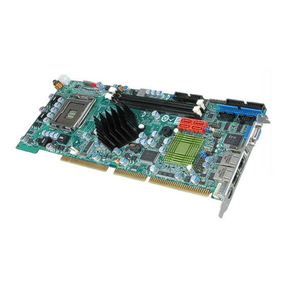
WSB-G41A CPU Card 1.1 Introduction Figure 1-1: WSB-G41A The WSB-G41A is a PCIMG 1.0 CPU card with an 800/1066/1333 MHz front side bus. The LGA775 accepts Intel® Core™2 Duo/Quad/Extreme processors and the card supports two DDR3 DIMMs up to 4.0 GB each (8.0 GB total). The WSB-G41A includes VGA video output and an optional DVI output. -
Page 15: Features
WSB-G41A CPU Card 1.3 Features Some of the WSB-G41A motherboard features are listed below: PCIMG 1.0 RoHS compliant LGA775 CPU socket Supports two DDR3 DIMMs Two Gigabit Ethernet connectors Four SATA connectors High Definition audio to connect to an optional audio kit Page 3... -
Page 16: Connectors
WSB-G41A CPU Card 1.4 Connectors The connectors on the WSB-G41A are shown in the figure below. Figure 1-2: Connectors Page 4... -
Page 17: Dimensions
WSB-G41A CPU Card 1.5 Dimensions The main dimensions of the WSB-G41A are shown in the diagram below. Figure 1-3: Dimensions (mm) Page 5... -
Page 18: Data Flow
WSB-G41A CPU Card 1.6 Data Flow F igure 1-4 shows the data flow between the system chipset, the CPU and other components installed on the motherboard. Figure 1-4: Data Flow Diagram Page 6... -
Page 19: Technical Specifications
WSB-G41A CPU Card 1.7 Technical Specifications WSB-G41A technical specifications are shown below. Specification WSB-G41A PCIMG 1.0 Form Factor Socket LGA775 Intel® Core™2 Duo/Quad/Extreme, CPU Supported Celeron Front Side Bus (FSB) 800/1066/1333 MHz Northbridge Chipset Intel® G41 Integrated Graphics DVI (WSB-G41A-DVI only) Memory Two 240-pin 4 GB (max.) 800/1066MHz dual-channel DDR3 SDRAM DIMM supported (system max. -
Page 20: Table 1-1: Technical Specifications
WSB-G41A CPU Card Specification WSB-G41A ATX supported Power Supply Power Consumption 5 V @ 7.13 A 12 V @ 0.27 A 5VBS @ 0.11 A Vcore @ 3.02 A 3D Mark2001SE with Intel® Core™2 Duo E8500 3.16GHz and two 2GB DDR3 modules Operating Temperature 0ºC ~ 60ºC( 32°F ~ 140°F), requires cooler and silicone heat sink paste... -
Page 21: Packing List
WSB-G41A CPU Card Chapter Packing List Page 9... -
Page 22: Anti-Static Precautions
WSB-G41A CPU Card 2.1 Anti-static Precautions WARNING! Static electricity can destroy certain electronics. Make sure to follow the ESD precautions to prevent damage to the product, and injury to the user. Make sure to adhere to the following guidelines: Wear an anti-static wristband: Wearing an anti-static wristband can prevent electrostatic discharge. -
Page 23: Packing List
WSB-G41A CPU Card 2.3 Packing List NOTE: If any of the components listed in the checklist below are missing, do not proceed with the installation. Contact the IEI reseller or vendor the WSB-G41A was purchased from or contact an IEI sales representative directly by sending an email to s ales@ieiworld.com The WSB-G41A is shipped with the following components:... -
Page 24: Optional Items
WSB-G41A CPU Card Quantity Item and Part Number Image Mini jumper pack (2.0mm) Utility CD Quick Installation Guide Table 2-1: Packing List 2.4 Optional Items The following are optional components which may be separately purchased: Item and Part Number Image CPU cooler kit 115W (P/N: CF-520-RS-R11) CPU cooler kit 130W... -
Page 25: Table 2-2: Optional Items
WSB-G41A CPU Card Item and Part Number Image FDD cable (P/N: 32200-000017-RS) LPT cable (P/N: 19800-000049-RS) Audio kit_ 5.1 Channel (P/N: AC-KIT08R-R10) Audio kit_ 7.1 Channel (P/N: AC-KIT-892HD-R10) SATA power cable (P/N: 32102-000100-200-RS) Table 2-2: Optional Items Page 13... -
Page 26: Connectors
WSB-G41A CPU Card Chapter Connectors Page 14... -
Page 27: Peripheral Interface Connectors
WSB-G41A CPU Card 3.1 Peripheral Interface Connectors This chapter details all the jumpers and connectors. 3.1.1 Layout The figure below shows all the connectors and jumpers. Figure 3-1: Connectors and Jumpers 3.1.2 Peripheral Interface Connectors The table below lists all the connectors on the board. Connector Type Label... -
Page 28: External Interface Panel Connectors
WSB-G41A CPU Card Connector Type Label Front Panel Connector 14-pin header F_PANEL1 Infrared Interface Connector 5-pin header Keyboard Connector 5-pin header Memory Slot DIMM slot DIMM1, DIMM2 IDE Connector 40-pin box header PIDE1 Parallel Port Connector 26-pin box header LPT1 SATA Drive Connectors 7-pin SATA drive SATA1, SATA2,... -
Page 29: Internal Peripheral Connectors
WSB-G41A CPU Card 3.2 Internal Peripheral Connectors The section describes all of the connectors on the WSB-G41A. 3.2.1 ATX Power Control Connector CN Label: ATXCTL1 3-pin wafer CN Type: CN Location: See Figure 3-2 CN Pinouts: See Table 3-3 The connector is for enabling an ATX power supply. When connected to the power supply, the power can be turned on and off with the front panel switch. -
Page 30: Battery Connector
WSB-G41A CPU Card This connector connects to an external audio kit. Figure 3-3: Audio Kit Connector Location Description Description ACZ_SYNC ACZ_BITCLK ACZ_SDOUT ACZ_PCBEEP ACZ_SDIN ACZ_RST# ACZ_VCC ACZ_GND ACZ_12 V ACZ_ GND Table 3-4: Audio Kit Connector Pinouts 3.2.3 Battery Connector CN Label: BAT1 2-pin wafer... -
Page 31: Cpu Fan Connector
WSB-G41A CPU Card Description Battery+ Ground Table 3-5: Battery Connector Pinouts 3.2.4 CPU Fan Connector CN Label: CPU_FAN1 CN Type: 4-pin wafer CN Location: See Figure 3-5 CN Pinouts: See Table 3-6 The fan connector attaches to a CPU cooling fan. Figure 3-5: CPU Fan Connector Location Description +12 V... -
Page 32: Dvi Connector
WSB-G41A CPU Card CN Pinouts: See Table 3-7 The CPU power input connector provides power to the CPU. Figure 3-6: CPU Power Input Connector Location Description +12 V +12 V Table 3-7: CPU Power Input Connector Pinouts 3.2.6 DVI Connector CN Label: DVI1 CN Type:... -
Page 33: Digital I/O Connector
WSB-G41A CPU Card Description Description Data 2- Data 2+ Hot Plug Detect Data0- Data 0+ DDC Clock DDC Data Data 1- Data 1+ Clock+ Clock- Table 3-8: DVI Connector Pinouts 3.2.7 Digital I/O Connector CN Label: DIO1 CN Type: 10-pin header CN Location: See Figure 3-8 CN Pinouts:... -
Page 34: Floppy Disk Connector
WSB-G41A CPU Card Description Description Output 3 Output 2 Output 1 Output 0 Input 3 Input 2 Input 1 Input 0 Table 3-9: Digital I/O Connector Pinouts 3.2.8 Floppy Disk Connector CN Label: FDD1 CN Type: 34-pin box header CN Location: See Figure 3-9 CN Pinouts: See Table 3-10... -
Page 35: Front Panel Connector
WSB-G41A CPU Card Description Description DIRECTION# STEP# WRITE DATA# WRITE GATE# TRACK 0# WRITE PROTECT# READ DATA# SIDE 1 SELECT# DISK CHANGE# Table 3-10: Floppy Drive Connector Pinouts 3.2.9 Front Panel Connector CN Label: F_PANEL1 CN Type: 14-pin header CN Location: See Figure 3-10 See Table 3-11 CN Pinouts:... -
Page 36: Infrared Interface Connector
WSB-G41A CPU Card Description Description GROUND Power button+ Speaker Power button- +5 V Reset- HDD LED- GROUND Table 3-11: Front Panel Connector Pinouts 3.2.10 Infrared Interface Connector CN Label: CN Type: 5-pin header CN Location: See Figure 3-11 CN Pinouts: See Table 3-12 The infrared connector attaches to an infrared receiver for use with remote controls. -
Page 37: Keyboard Connector
WSB-G41A CPU Card 3.2.11 Keyboard Connector CN Label: 5-pin wafer CN Type: CN Location: See Figure 3-12 CN Pinouts: See Table 3-13 The keyboard connector can be used to install a PS/2 keyboard. Figure 3-12: Keyboard Connector Location Description KEYBOARD CLOCK KEYBOARD DATA GROUND Table 3-13: Keyboard Connector Pinouts... -
Page 38: Ide Connector
WSB-G41A CPU Card Figure 3-13: Memory Card Slot Location 3.2.13 IDE Connector CN Label: PIDE1 CN Type: 40-pin box header CN Location: See Figure 3-14 See Table 3-14 CN Pinouts: Connects to IDE hard drives and optical drives. Figure 3-14: IDE Connector Location Description Description RESET#... -
Page 39: Parallel Port Connector
WSB-G41A CPU Card Description Description DATA 1 DATA 14 DATA 0 DATA 15 GROUND IDE DRQ GROUND IOW# GROUND IOR# GROUND IDE CHRDY BALE—DEFAULT IDE DACK GROUND INTERRUPT PDIAG# HDC CS0# HDC CS1# HDD ACTIVE# GROUND Table 3-14: IDE Connector Pinouts 3.2.14 Parallel Port Connector CN Label: LPT1... -
Page 40: Sata Drive Connectors
WSB-G41A CPU Card Description Description STROBE# AUTO FORM FEED# DATA0 ERROR# DATA1 INITIALIZE# DATA2 PRINTER SELECT LN# DATA3 GROUND DATA4 GROUND DATA5 GROUND DATA6 GROUND DATA7 GROUND ACKNOWLEDGE# GROUND BUSY GROUND PAPER EMPTY GROUND PRINTER SELECT Table 3-15: Parallel Port Connector Pinouts 3.2.15 SATA Drive Connectors CN Label: SATA1, SATA2, SATA3, SATA4... -
Page 41: Serial Port Connector
WSB-G41A CPU Card Description Table 3-16: SATA Drive Connector Pinouts 3.2.16 Serial Port Connector CN Label: COM1, COM2 10-pin box header CN Type: CN Location: See Figure 3-17 CN Pinouts: See Table 3-17 This connector provides RS-232 communications. Figure 3-17: Serial Port Connector Location Description Data Carrier Detect (DCD1) Receive Data (RXD1) -
Page 42: Spi Flash Connector
WSB-G41A CPU Card Description Data Set Ready (DSR1) Request To Send (RTS1) Clear To Send (CTS1) Ring Indicator (RI1) Table 3-17: Serial Port Connector Pinouts 3.2.17 SPI Flash Connector CN Label: JSPI1 8-pin header CN Type: CN Location: See Figure 3-18 CN Pinouts: See Table 3-18 The 8-pin SPI Flash connector is used to flash the BIOS. -
Page 43: Usb Connectors
WSB-G41A CPU Card 3.2.18 USB Connectors CN Label: USB12, USB34, USB56 8-pin header CN Type: CN Location: See Figure 3-19 CN Pinouts: See Table 3-19 The USB connectors connect to USB devices. Each pin header provides two USB ports. Figure 3-19: USB Connector Pinout Locations Description Description DATA1-... -
Page 44: External Peripheral Interface Connector Panel
WSB-G41A CPU Card 3.3 External Peripheral Interface Connector Panel The figure below shows the external peripheral interface connector (EPIC) panel. The EPIC panel consists of the following: Figure 3-20: External Peripheral Interface Connector 3.3.1 Keyboard/Mouse Connector CN Label: KB_MS1 CN Type: PS/2 CN Location: See Figure 3-20... -
Page 45: Lan Connector
WSB-G41A CPU Card Description KEYBOARD CLOCK MOUSE CLOCK Table 3-20: Keyboard Connector Pinouts 3.3.2 LAN Connector CN Label: LAN1, LAN2 CN Type: RJ-45 CN Location: See Figure 3-20 CN Pinouts: See Table 3-21 The LAN connector connects to a local network. Description Description MDIA3-... -
Page 46: Vga Connector
WSB-G41A CPU Card Description Description Table 3-22: USB Port Pinouts 3.3.4 VGA Connector CN Label: VGA1 CN Type: 15-pin Female CN Location: See Figure 3-20 CN Pinouts: See Figure 3-22 and Table 3-23 The VGA connector connects to a monitor that accepts a standard VGA input. Figure 3-22: VGA Connector Description Description... -
Page 47: Installation
WSB-G41A CPU Card Chapter Installation Page 35... -
Page 48: Anti-Static Precautions
WSB-G41A CPU Card 4.1 Anti-static Precautions WARNING: Failure to take ESD precautions during the installation of the WSB-G41A may result in permanent damage to the WSB-G41A and severe injury to the user. Electrostatic discharge (ESD) can cause serious damage to electronic components, including the WSB-G41A. -
Page 49: Basic Installation
WSB-G41A CPU Card WARNING: The installation instructions described in this manual should be carefully followed in order to prevent damage to the components and injury to the user. Before and during the installation please DO the following: Read the user manual: The user manual provides a complete description of the WSB-G41A installation instructions and configuration options. -
Page 50: Cpu Installation
WSB-G41A CPU Card 4.3.1 CPU Installation NOTE: To enable Hyper-Threading, the CPU and chipset must both support it. WARNING: CPUs are expensive and sensitive components. When installing the CPU please be careful not to damage it in anyway. Make sure the CPU is installed properly and ensure the correct cooling kit is properly installed. -
Page 51: Figure 4-2: Remove Protective Cover
WSB-G41A CPU Card Step 1: Remove the protective cover. The black protective cover can be removed by pulling up on the tab labeled "Remove". See Figure 4-2. Figure 4-2: Remove Protective Cover Step 2: Open the socket. Disengage the load lever by pressing the lever down and slightly outward to clear the retention tab. -
Page 52: Figure 4-4: Insert The Socket Lga775 Cpu
WSB-G41A CPU Card Step 5: Correctly position the CPU. Match the Pin 1 mark with the cut edge on the CPU socket. Step 6: Align the CPU pins. Locate pin 1 and the two orientation notches on the CPU. Carefully match the two orientation notches on the CPU with the socket alignment keys. -
Page 53: Cooling Kit Installation
WSB-G41A CPU Card 4.3.2 Cooling Kit Installation WARNING: DO NOT use the original Intel® heat sink and fan. A proprietary one is recommended. Figure 4-5: Cooling Kits The cooling kit can be bought from IEI. The cooling kit has a heatsink and fan. WARNING: Do not wipe off (accidentally or otherwise) the pre-sprayed layer of thermal paste on the bottom of the heat sink. -
Page 54: Figure 4-6: Securing The Heat Sink To The Wsb-G41A
WSB-G41A CPU Card Step 3: Mount the cooling kit. Gently place the cooling kit on top of the CPU. Make sure the four threaded screws on the corners of the cooling kit properly pass through the predrilled holes on the bottom of the PCB. Step 4: Secure the cooling kit. -
Page 55: Dimm Installation
WSB-G41A CPU Card 4.3.3 DIMM Installation To install a DIMM, please follow the steps below and refer to Figure 4-7. Figure 4-7: DIMM Installation Step 1: Open the DIMM socket handles. Open the two handles outwards as far as they can. See Figure 4-7. Step 2: Align the DIMM with the socket. -
Page 56: Cpu Card Installation
WSB-G41A CPU Card NOTE: IEI has a wide range of backplanes available. Please contact your WSB-G41A vendor, reseller or and IEI sales representative at sales@ieiworld.com or visit the IEI website at http://www.ieiworld.com to find out more about the available chassis. 4.3.5 CPU Card Installation To install the WSB-G41A CPU card onto the backplane, carefully align the CPU card interface connectors with the corresponding socket on the backplane. -
Page 57: At/Atx Power Select Jumper Settings
WSB-G41A CPU Card Description Label Type Wake-on LAN jumper JLAN_PWR1 6-pin header Table 4-1: Jumpers 4.4.1 AT/ATX Power Select Jumper Settings Jumper Label: JAUTO1 Jumper Type: 2-pin header Jumper Location: See Figure 4-8 See Table 4-2 Jumper Settings: The AT/ATX Power Select jumper specifies the systems power mode as AT or ATX. Figure 4-8: AT/ATX Power Jumper Location Setting Description... -
Page 58: Wake-On Lan Jumper
WSB-G41A CPU Card To reset the BIOS, move the jumper to the "Clear BIOS" position for 3 seconds or more, and then move back to the default position. Figure 4-9: Clear BIOS Jumper Location Description Normal Clear BIOS Table 4-3: Clear BIOS Jumper Settings 4.4.3 Wake-on LAN Jumper CN Label: JLAN_PWR1... -
Page 59: Internal Peripheral Device Connections
WSB-G41A CPU Card PIN NO. DESCRIPTION Short 2-4 LAN2 Wakeup Enabled Short 4-6 LAN2 Wakeup Disabled Table 4-4: Wake-on LAN Connector Pinouts 4.5 Internal Peripheral Device Connections This section outlines the installation of peripheral devices to the onboard connectors. 4.5.1 Audio Kit Installation The Audio Kit that came with the WSB-G41A connects to the audio connector on the WSB-G41A. -
Page 60: Dual Rs-232 Cable With Slot Bracket
WSB-G41A CPU Card Figure 4-11: Audio Kit Cable Connection Step 3: Connect the audio devices. Connect speakers to the line-out audio jack. Connect the output of an audio device to the line-in audio jack. Connect a microphone to the mic-in audio jack.Step 0: 4.5.2 Dual RS-232 Cable with Slot Bracket The dual RS-232 cable slot connector consists of two connectors attached to two... -
Page 61: Sata Drive Connection
WSB-G41A CPU Card Figure 4-12: Dual RS-232 Cable Installation Step 3: Secure the bracket. The dual RS-232 connector has two D-sub 9 male connectors secured on a bracket. To secure the bracket to the chassis please refer to the reference material that came with the chassis. Step 0: 4.5.3 SATA Drive Connection The WSB-G41A is shipped with two SATA drive cables and one SATA drive power cable. -
Page 62: Figure 4-13: Sata Drive Cable Connection
WSB-G41A CPU Card Figure 4-13: SATA Drive Cable Connection Step 3: Connect the cable to the SATA disk. Connect the connector on the other end of the cable to the connector at the back of the SATA drive. See Figure 4-14. Step 4: Connect the SATA power cable. -
Page 63: Usb Cable (Dual Port) With Slot Bracket
WSB-G41A CPU Card 4.5.4 USB Cable (Dual Port) with Slot Bracket The WSB-G41A is shipped with a dual port USB 2.0 cable. To connect the USB cable connector, please follow the steps below. Step 1: Locate the connectors. The locations of the USB connectors are shown in Chapter 3. -
Page 64: External Peripheral Interface Connection
WSB-G41A CPU Card Step 4: Attach the bracket to the chassis. The USB 2.0 connectors are attached to a bracket. To secure the bracket to the chassis please refer to the installation instructions that came with the chassis.Step 0: 4.6 External Peripheral Interface Connection This section describes connecting devices to the external connectors on the WSB-G41A. -
Page 65: Lan Connection
WSB-G41A CPU Card Step 3: Connect the keyboard and mouse. Connect the keyboard and mouse to the appropriate connector. The keyboard and mouse connectors can be distinguished from each other by looking at the small graphic at the top of the connector. -
Page 66: Usb Device Connection
WSB-G41A CPU Card 4.6.3 USB Device Connection There are two external USB 2.0 connectors. Both connectors are perpendicular to the WSB-G41A. To connect a USB 2.0 or USB 1.1 device, please follow the instructions below. Step 1: Located the USB connectors. The locations of the USB connectors are shown in Chapter 4. -
Page 67: Software Installation
WSB-G41A CPU Card Step 2: Align the VGA connector. Align the male DB-15 connector on the VGA screen cable with the female DB-15 connector on the external peripheral interface. Step 3: Insert the VGA connector. Once the connectors are properly aligned with the insert the male connector from the VGA screen into the female connector on the WSB-G41A. -
Page 68: Figure 4-20: Introduction Screen
WSB-G41A CPU Card NOTE: If the installation program doesn't start automatically: Click "Start->My Computer->CD Drive->autorun.exe" Step 2: The driver main menu appears (Figure 4-20). Figure 4-20: Introduction Screen Step 3: Click WSB-G41A. Step 4: A new screen with a list of available drivers appears (Figure 4-21). Page 56... -
Page 69: Figure 4-21: Available Drivers
WSB-G41A CPU Card Figure 4-21: Available Drivers Step 5: Install all of the necessary drivers in this menu. S t e p 0 : Page 57... -
Page 70: Bios
WSB-G41A CPU Card Chapter BIOS Page 58... -
Page 71: Introduction
WSB-G41A CPU Card 5.1 Introduction The BIOS is programmed onto the BIOS chip. The BIOS setup program allows changes to certain system settings. This chapter outlines the options that can be changed. 5.1.1 Starting Setup The AMI BIOS is activated when the computer is turned on. The setup program can be activated in one of two ways. -
Page 72: Getting Help
WSB-G41A CPU Card Function F2 /F3 key Change color from total 16 colors. F2 to select color forward. F10 key Save all the CMOS changes, only for Main Menu Table 5-1: BIOS Navigation Keys 5.1.3 Getting Help When F1 is pressed a small help window describing the appropriate keys to use and the possible selections for the highlighted item appears. -
Page 73: Main
WSB-G41A CPU Card 5.2 Main The Main BIOS menu (BIOS Menu 1) appears when the BIOS Setup program is entered. The Main menu gives an overview of the basic system information. BIOS SETUP UTILITY Main Advanced PCIPNP Boot Security Chipset Exit System Overview ... -
Page 74: Advanced
WSB-G41A CPU Card The System Overview field also has two user configurable fields: System Time [xx:xx:xx] Use the System Time option to set the system time. Manually enter the hours, minutes and seconds. System Date [xx/xx/xx] Use the System Date option to set the system date. Manually enter the day, month and year. -
Page 75: Cpu Configuration
WSB-G41A CPU Card BIOS SETUP UTILITY Main Advanced PCIPNP Boot Security Chipset Exit Advanced Settings WARNING: Setting wrong values in below sections may cause system to malfunction > CPU Configuration > IDE Configuration Select Screen > Floppy Configuration ... -
Page 76: Ide Configuration
WSB-G41A CPU Card Frequency: Lists the CPU processing speed FSB Speed: Lists the FSB speed Cache L1: Lists the CPU L1 cache size Cache L2: Lists the CPU L2 cache size 5.3.2 IDE Configuration Use the IDE Configuration menu (BIOS Menu 4) to change and/or set the configuration of the IDE devices installed in the system. -
Page 77: Ide Master, Ide Slave
WSB-G41A CPU Card Enhanced Configures the on-board ATA/IDE controller to be in EFAULT Enhanced mode. In this mode, IDE channels and SATA channels are separated. This mode supports up to 6 storage devices. Some legacy OS do not support this mode. - Page 78 WSB-G41A CPU Card BIOS SETUP UTILITY Advanced Primary IDE Master Device :Not Detected Type [Auto] LBA/Large Mode [Auto] Block (Multi-Sector Transfer) [Auto] Select Screen PIO Mode [Auto] Select Item DMA Mode [Auto] Change Option S.M.A.R.T. [Auto] General Help 32Bit Data Transfer...
- Page 79 WSB-G41A CPU Card Type [Auto] Use the Type BIOS option select the type of device the AMIBIOS attempts to boot from after the Power-On Self-Test (POST) is complete. Not Installed BIOS is prevented from searching for an IDE disk drive on the specified channel.
- Page 80 WSB-G41A CPU Card Disabled BIOS is prevented from using Multi-Sector Transfer on the specified channel. The data to and from the device occurs one sector at a time. BIOS auto detects Multi-Sector Transfer support on the Auto EFAULT drive on the specified channel.
-
Page 81: Floppy Configuration
WSB-G41A CPU Card S.M.A.R.T [Auto] Use the S.M.A.R.T option to auto-detect, disable or enable Self-Monitoring Analysis and Reporting Technology (SMART) on the drive on the specified channel. S.M.A.R.T predicts impending drive failures. The S.M.A.R.T BIOS option enables or disables this function. ... -
Page 82: Super Io Configuration
WSB-G41A CPU Card Floppy A Use the Floppy A option to configure the floppy disk drive. Options are listed below: Disabled 1.44 MB 3 1/2” 5.3.4 Super IO Configuration Use the Super IO Configuration menu (BIOS Menu 7) to set or change the configurations for the FDD controllers, parallel ports and serial ports. - Page 83 WSB-G41A CPU Card Parallel Port Mode [Normal] Use the Parallel Port Mode option to select the mode the parallel port operates in. The normal parallel port mode is the standard mode Normal EFAULT for parallel port operation. The parallel port operates in the enhanced parallel port mode (EPP).
- Page 84 WSB-G41A CPU Card Disabled No base address is assigned to Serial Port 1 Serial Port 1 I/O port address is 3F8 and the interrupt 3F8/IRQ4 EFAULT address is IRQ4 3E8/IRQ4 Serial Port 1 I/O port address is 3E8 and the interrupt address is IRQ4 ...
-
Page 85: Hardware Health Configuration
WSB-G41A CPU Card Normal Serial Port 2 mode is normal EFAULT Serial Port 2 mode is IrDA IrDA ASK IR Serial Port 2 mode is ASK IR 5.3.5 Hardware Health Configuration The Hardware Health Configuration menu (BIOS Menu 8) shows the operating temperature, fan speeds and system voltages. - Page 86 WSB-G41A CPU Card Automatic mode The fan adjusts its speed using these settings: Temp. Limit of OFF Temp. Limit of Start Fan Start PWM Slope PWM 1 Manually The fan spins at the speed set in: mode Fan PWM control ...
- Page 87 WSB-G41A CPU Card PWM Maximum Mode: 127 Slope PWM [0.5 PWM] A bigger value will increase the fan speed in big amounts. A smaller value will increase the speed more gradually. 0.125 PWM 0.25 PWM 0.5 PWM ...
-
Page 88: Power Configuration
WSB-G41A CPU Card +12 V +1.5 V +1.5 V (DDR3) 5V Dual VBAT 5.3.6 Power Configuration Use the Power Configuration menu (BIOS Menu 10) configures the Advanced Configuration and Power Interface (ACPI) and Power Management (APM) options. BIOS SETUP UTILITY Advanced Select AT/ATX Power [ATX Power]... -
Page 89: Apm Configuration
WSB-G41A CPU Card BIOS SETUP UTILITY Advanced ACPI Settings Suspend mode [S1 (POS)] Select Screen Select Item Change Option General Help Save and Exit Exit v02.61 ©Copyright 1985-2006, American Megatrends, Inc. BIOS Menu 10: ACPI Settings ... - Page 90 WSB-G41A CPU Card BIOS SETUP UTILITY Advanced APM Configuration Restore on AC Power Loss [Last State] Power Button Mode [On/Off] Advanced Resume Event Controls Resume on Keyboard/Mouse [Disabled] Select Screen Resume On Ring [Disabled] Select Item Resume on PCI-Express WAKE# [Disabled] Change Option...
- Page 91 WSB-G41A CPU Card Resume on Keyboard/Mouse [Disabled] Use the Resume on Keyboard/Mouse BIOS option to enable activity on either the keyboard or mouse to rouse the system from a suspend or standby state. That is, the system is roused when the mouse is moved or a button on the keyboard is pressed. ...
-
Page 92: Remote Access Configuration
WSB-G41A CPU Card Disabled The real time clock (RTC) cannot generate a wake EFAULT event If selected, the following appears with values that Enabled can be selected: RTC Alarm Date (Days) System Time After setting the alarm, the computer turns itself on from a suspend state when the alarm goes off. -
Page 93: Usb Configuration
WSB-G41A CPU Card Disabled Remote access is disabled. EFAULT Remote access configuration options shown below Enabled appear: Serial Port Number Serial Port Mode Flow Control Redirection after BIOS POST Terminal Type These configuration options are discussed below. 5.3.8 USB Configuration Use the USB Configuration menu (BIOS Menu 13) to read USB configuration information and configure the USB settings. - Page 94 WSB-G41A CPU Card USB Devices Enabled The USB Devices Enabled field lists the USB devices that are enabled on the system USB Functions [Enabled] Use the USB Function BIOS option to enable or disable USB function support. Disabled USB function support disabled ...
-
Page 95: Pcipnp
WSB-G41A CPU Card FullSpeed The controller is capable of operating at 12 Mb/s The controller is capable of operating at 480 Mb/s HiSpeed EFAULT 5.4 PCI/PnP Use the PCI/PnP menu (BIOS Menu 14) to configure advanced PCI and PnP settings. WARNING! Setting wrong values for the BIOS selections in the PCIPnP BIOS menu may cause the system to malfunction. - Page 96 WSB-G41A CPU Card IRQ# [Available] Use the IRQ# address to specify what IRQs can be assigned to a particular peripheral device. Available The specified IRQ is available to be used by EFAULT PCI/PnP devices The specified IRQ is reserved for use by Legacy ISA Reserved devices Available IRQ addresses are:...
-
Page 97: Boot
WSB-G41A CPU Card DMA Channel 5 DMA Channel 6 DMA Channel 7 Reserved Memory Size [Disabled] Use the Reserved Memory Size BIOS option to specify the amount of memory that should be reserved for legacy ISA devices. ... -
Page 98: Boot Settings Configuration
WSB-G41A CPU Card 5.5.1 Boot Settings Configuration Use the Boot Settings Configuration menu (BIOS Menu 16) to configure advanced system boot options. BIOS SETUP UTILITY Boot Boot Settings Configuration Quick Boot [Enabled] Quiet Boot [Enabled] AddOn ROM Display Mode [Force BIOS] Bootup Num-Lock [On]... - Page 99 WSB-G41A CPU Card AddOn ROM Display Mode [Force BIOS] Use the AddOn ROM Display Mode option to allow add-on ROM (read-only memory) messages to be displayed. Force BIOS The system forces third party BIOS to display EFAULT during system boot. ...
-
Page 100: Security
WSB-G41A CPU Card 5.6 Security Use the Security menu (BIOS Menu 17) to set system and user passwords. BIOS SETUP UTILITY Main Advanced PCIPNP Boot Security Chipset Exit Security Settings Supervisor Password :Not Installed User Password :Not Installed Change Supervisor Password Change User Password ... - Page 101 WSB-G41A CPU Card WARNING! Setting the wrong values for the Chipset BIOS selections in the Chipset BIOS menu may cause the system to malfunction. BIOS SETUP UTILITY Main Advanced PCIPNP Boot Security Chipset Exit Advanced Chipset Settings WARNING: Setting wrong values in below section may cause system to malfunction.
-
Page 102: Northbridge Configuration
WSB-G41A CPU Card 5.7.1 Northbridge Configuration Use the Northbridge Chipset Configuration menu (BIOS Menu 19) to configure the Northbridge chipset. BIOS SETUP UTILITY Chipset North Bridge Chipset Configuration Memory Remap Feature [Enabled] PCI MMIO Allocation: 4GB to 3072MB Memory Hole [Disabled] Initate Graphic Adapter [PCI/IGD]... - Page 103 WSB-G41A CPU Card 15 MB–16 MB Between 15 MB and 16 MB of memory is reserved for ISA expansion cards Initiate Graphic Adapter Use the Initiate Graphic Adapter option to select the graphics controller used as the primary boot device. Select either an integrated graphics controller (IGD) or a combination of PCI graphics controller, a PCI express (PEG) controller or an IGD.
-
Page 104: Video Function Configuration
WSB-G41A CPU Card 5.7.1.1 Video Function Configuration Use the Video Function Configuration submenu to configure video settings. BIOS SETUP UTILITY Chipset Video Function Configuration Boot Display Device [Auto] Select Screen Select Item Change Option General Help Save and Exit Exit v02.61 ©Copyright 1985-2006, American Megatrends, Inc. -
Page 105: Exit
WSB-G41A CPU Card BIOS SETUP UTILITY Chipset Southbridge Chipset Configuration Audio Controller [Auto] Spread Spectrum Mode [Disabled] Select Screen Select Item Change Option General Help Save and Exit Exit v02.61 ©Copyright 1985-2006, American Megatrends, Inc. BIOS Menu 21: Southbridge Chipset Configuration ... - Page 106 WSB-G41A CPU Card BIOS SETUP UTILITY Main Advanced PCIPNP Boot Security Chipset Exit Exit Options Save Changes and Exit Discard Changes and Exit Discard Changes Load Optimal Defaults Select Screen Load Failsafe Defaults Select Item Enter Go to Sub Screen General Help Save and Exit Exit...
-
Page 107: Abios Options
WSB-G41A CPU Card Appendix BIOS Options Page 95... - Page 108 WSB-G41A CPU Card Below is a list of BIOS configuration options in the BIOS chapter. System Overview .........................61 System Time [xx:xx:xx] .......................62 System Date [xx/xx/xx] ......................62 ATA/IDE Configurations [Enhanced] .................64 Configure SATA Channels [Before PATA] ................65 ...
- Page 109 WSB-G41A CPU Card Resume on Ring [Disabled] ....................79 Resume on PCI-Express WAKE# [Disabled]..............79 Resume On RTC Alarm [Disabled]..................79 Remote Access [Disabled]....................80 USB Configuration.......................81 USB Devices Enabled......................82 USB Functions [Enabled]....................82 USB 2.0 Controller [Enabled]....................82 ...
-
Page 110: B Terminology
WSB-G41A CPU Card Appendix Terminology Page 98... - Page 111 WSB-G41A CPU Card AC ’97 Audio Codec 97 (AC’97) refers to a codec standard developed by Intel® in 1997. ACPI Advanced Configuration and Power Interface (ACPI) is an OS-directed configuration, power management, and thermal management interface. AHCI Advanced Host Controller Interface (AHCI) is a SATA Host controller register-level interface.
- Page 112 WSB-G41A CPU Card DIMM Dual Inline Memory Modules are a type of RAM that offer a 64-bit data bus and have separate electrical contacts on each side of the module. The digital inputs and digital outputs are general control signals that control the on/off circuit of external devices or TTL devices.
- Page 113 WSB-G41A CPU Card LVDS Low-voltage differential signaling (LVDS) is a dual-wire, high-speed differential electrical signaling system commonly used to connect LCD displays to a computer. POST The Power-on Self Test (POST) is the pre-boot actions the system performs when the system is turned-on. Random Access Memory (RAM) is volatile memory that loses data when power is lost.
-
Page 114: C Watchdog Timer
WSB-G41A CPU Card Appendix Watchdog Timer Page 102... - Page 115 WSB-G41A CPU Card NOTE: The following discussion applies to DOS. Contact IEI support or visit the IEI website for drivers for other operating systems. The Watchdog Timer is a hardware-based timer that attempts to restart the system when it stops working. The system may stop working because of external EMI or software bugs. The Watchdog Timer ensures that standalone systems like ATMs will automatically attempt to restart in the case of system problems.
- Page 116 WSB-G41A CPU Card NOTE: The Watchdog Timer is activated through software. The software application that activates the Watchdog Timer must also deactivate it when closed. If the Watchdog Timer is not deactivated, the system will automatically restart after the Timer has finished its countdown. EXAMPLE PROGRAM: ;...
-
Page 117: D Digital I/O Interface
WSB-G41A CPU Card Appendix Digital I/O Interface Page 105... -
Page 118: Introduction
WSB-G41A CPU Card D.1 Introduction The digital I/O is used for machine control and automation. D.2 DIO Connector Pinouts Located in the Connectors section of this document. D.3 Assembly Language Example ;************************************************** ; DIO Port: 0A21h[3:0] (4 Out) 0A22h[3:0] (4 In) ;************************************************** ;================================================== ;... -
Page 119: E Hazardous Materials Disclosure
WSB-G41A CPU Card Appendix Hazardous Materials Disclosure Page 107... -
Page 120: Hazardous Materials Disclosure Table For Ipb Products Certified As Rohs Compliant Under 2002/95/Ec Without Mercury
WSB-G41A CPU Card E.1 Hazardous Materials Disclosure Table for IPB Products Certified as RoHS Compliant Under 2002/95/EC Without Mercury The details provided in this appendix are to ensure that the product is compliant with the Peoples Republic of China (China) RoHS standards. The table below acknowledges the presences of small quantities of certain materials in the product, and is applicable to China RoHS only. - Page 121 WSB-G41A CPU Card Part Name Toxic or Hazardous Substances and Elements Lead Mercury Cadmium Hexavalent Polybrominated Polybrominated (Pb) (Hg) (Cd) Chromium Biphenyls Diphenyl (CR(VI)) (PBB) Ethers (PBDE) Housing Display Printed Circuit Board Metal Fasteners Cable Assembly Fan Assembly Power Supply Assemblies Battery This toxic or hazardous substance is contained in all of the homogeneous materials for the part is...
- Page 122 WSB-G41A CPU Card 此附件旨在确保本产品符合中国 RoHS 标准。以下表格标示此产品中某有毒物质的含量符 合中国 RoHS 标准规定的限量要求。 本产品上会附有”环境友好使用期限”的标签,此期限是估算这些物质”不会有泄漏或突变”的 年限。本产品可能包含有较短的环境友好使用期限的可替换元件,像是电池或灯管,这些元 件将会单独标示出来。 部件名称 有毒有害物质或元素 铅 汞 镉 六价铬 多溴联苯 多溴二苯 醚 (Pb) (Hg) (Cd) (CR(VI)) (PBB) (PBDE) 壳体 显示 印刷电路板 金属螺帽 电缆组装 风扇组装 电力供应组装 电池 O: 表示该有毒有害物质在该部件所有物质材料中的含量均在 SJ/T11363-2006 标准规定的限量要求以下。 X: 表示该有毒有害物质至少在该部件的某一均质材料中的含量超出 SJ/T11363-2006 标准规定的限量要求。 Page 110...
Need help?
Do you have a question about the WSB-G41A-R11 and is the answer not in the manual?
Questions and answers