Table of Contents
Advertisement
Quick Links
SICAM RTUs
SICAM CMIC
User Manual
DC8-001-2.09
Preface
Open Source Software
Table of Contents
Installation
Interfaces and Circuitry
Preparing the Engineering
Engineering via SICAM TOOLBOX II
Engineering via SICAM WEB
Service
Variables in the Instruction List
Examples for Application Programs
Error Handling
Set Up Dial-Up Connection via PPP
Install Security Certificate
Use Cases
Glossary
1
2
3
4
5
6
A
B
C
D
E
F
Advertisement
Table of Contents

Related Manuals for Siemens SICAM CMIC


Summary of Contents for Siemens SICAM CMIC
- Page 1 Preface Open Source Software SICAM RTUs Table of Contents Installation SICAM CMIC Interfaces and Circuitry User Manual Preparing the Engineering Engineering via SICAM TOOLBOX II Engineering via SICAM WEB Service Variables in the Instruction List Examples for Application Programs Error Handling...
- Page 2 Disclaimer of Liability Copyright Although we have carefully checked the contents of this publication Copyright © Siemens AG 2016 for conformity with the hardware and software described, we cannot The reproduction, transmission or use of this document or its con- guarantee complete conformity since errors cannot be excluded.
-
Page 3: Installation
Preface Purpose of this manual This manual describes how to install and parameterize a SICAM CMIC system, which errors may occur and which are the existing diagnostic options. Particularly it contains the following information: · Safety instructions · Installation instructions ·... -
Page 4: Service
Preface Conventions Used · Manuals to be referred to are represented in italics, such as for instance SICAM CMIC System Description, chapter "System Overview". · Outputs visible on the screen are described in this font. · Inputs via keyboard or mouse keys and visible on the screen are described in this font. - Page 5 Fax: +43 51707 55243 power-academy.ptd@siemens.com power-academy.at@siemens.com Schenectady, NY, USA Hebburn, United Kingdom Phone: +1 518 395 5005 Phone: +44 1914 953449 Fax: +1 518 346 2777 Fax: +44 1914 953693 pti-edpro.ptd@siemens.com pti-training.stdl.uk@siemens.com SICAM RTUs, User Manual SICAM CMIC DC8-001-2.09, Edition 08.2016...
- Page 6 As used in the safety notes contained in this manual, qualified personnel are those persons who are authorized to commission, release, ground, and tag devices, systems, and electrical circuits in accordance with safety standards. SICAM RTUs, User Manual SICAM CMIC DC8-001-2.09, Edition 08.2016...
- Page 7 The equipment (device, module) must not be used for any other purposes than those de- scribed in the Catalog and the Technical Description. If it is used together with third-party de- vices and components, these must be recommended or approved by Siemens. Correct and safe operation of the product requires adequate transportation, storage, installa- tion, and mounting as well as appropriate use and maintenance.
- Page 8 Preface SICAM RTUs, User Manual SICAM CMIC DC8-001-2.09, Edition 08.2016...
- Page 9 Insofar as the applicable Open Source Software License Conditions provide for it you can or- der the source code of the Open Source Software from your Siemens sales contact - against payment of the shipping and handling charges - for a period of at least 3 years since purchase of the Product.
- Page 10 Open Source Software Used in SICAM CMIC SICAM RTUs, User Manual SICAM CMIC DC8-001-2.09, Edition 08.2016...
-
Page 11: Table Of Contents
Power Supply ....................44 1.8.1 Switching the System On and Off .............. 44 SD Card ......................45 1.9.1 Inserting the SD Card ................45 1.9.2 Removing the SD Card ................45 SICAM RTUs, User Manual SICAM CMIC DC8-001-2.09, Edition 08.2016... - Page 12 3.2.2.2 Program WEBcmic ................68 Loadable Firmwares ..................69 Integrated Protocol SNMP ................70 3.4.1 Download of the SICAM CMIC MIB-Files ........... 70 3.4.2 Import of the MIB-Files in MIB-Browser ............70 3.4.3 Display of SNMP-Variables in MIB-Browser ..........71 SD Card ......................
- Page 13 Hardware Configuration ..............110 4.1.5.2 System-Technical Settings ..............111 4.1.5.2.1 Communication ................111 4.1.5.2.2 Periphery ..................111 4.1.5.3 Process-Technical Settings ..............112 4.1.5.3.1 Levels .................... 112 4.1.5.3.2 Types .................... 112 4.1.5.3.3 Images ..................113 SICAM RTUs, User Manual SICAM CMIC DC8-001-2.09, Edition 08.2016...
- Page 14 Basic Settings ..................135 5.1.2.1 Authentication Procedure ..............136 5.1.2.1.1 Authentication via Locally Stored Credentials ......... 136 5.1.2.1.2 Authentication via External Service ..........137 5.1.2.2 Change Web Server Password ............138 SICAM RTUs, User Manual SICAM CMIC DC8-001-2.09, Edition 08.2016...
- Page 15 5.1.9.4.4 Parameters with Assignment on the AI Module ......204 5.1.9.4.5 Parameters with Assignment on the AO Module......209 5.1.9.5 Circuitry of Signals ................211 5.1.9.5.1 Binary Information Acquisition ............212 SICAM RTUs, User Manual SICAM CMIC DC8-001-2.09, Edition 08.2016...
- Page 16 Load Application Programm Offline ..........251 5.2.2.1.3 Export Application Program ............251 5.2.2.1.4 Syntax Check ................252 5.2.2.2 Test Functions ..................252 5.2.2.2.1 Statistic Information ............... 253 5.2.2.2.2 Display Current Value of Selected Variables ........254 SICAM RTUs, User Manual SICAM CMIC DC8-001-2.09, Edition 08.2016...
- Page 17 System Diagnosis ................296 6.3.2.3 System Performance ................298 6.3.2.4 Diagnosis of the Open-/Closed-Loop Control Function ......298 6.3.3 SICAM WEB .................... 300 6.3.3.1 Connection Possibilities for the Diagnosis ........... 300 SICAM RTUs, User Manual SICAM CMIC DC8-001-2.09, Edition 08.2016...
- Page 18 Transfer an Input to a Signalling Output and to a Command Output ....322 Combine two Inputs with AND ..............323 Linear Adaptation with Value Selection ............324 Operating Hours Counter ................325 Bounce Suppression ..................327 Setpoint Command ..................329 SICAM RTUs, User Manual SICAM CMIC DC8-001-2.09, Edition 08.2016...
- Page 19 SICAM CMIC as Telecontrol Substation ............396 SICAM CMIC as Telecontrol Substation with Node Function (Protocol Converter) ....................397 SICAM CMIC as Telecontrol Substation with Integrated Switch for External System Connection ..................398 SICAM CMIC as Telecontrol Substation with Integrated Switch for SICAM TOOLBOX II Connection ................
- Page 20 Table of Contents Glossary ..........................405 SICAM RTUs, User Manual SICAM CMIC DC8-001-2.09, Edition 08.2016...
-
Page 21: Installation
Power Supply ....................44 SD Card ......................45 This chapter describes the structure of the system SICAM CMIC, how and where it may be in- stalled, and how the wirings are to be accomplished. SICAM RTUs, User Manual SICAM CMIC... -
Page 22: Mechanical Design
On the right side of the housing is the BUS-connector for the SICAM TM I/O coupling module. It is covered with a label. On the bottom side of the device are the connections for the process signals as well as for the supply voltage. SICAM RTUs, User Manual SICAM CMIC DC8-001-2.09, Edition 08.2016... -
Page 23: Locking Hook
Protection class II / protective insulation The documentation must be observed SIEMENS SICAM CMIC Input: = 18 V - 70 V = 1,2 A - 0,6 A 00-00-00-00-00-00 BF0000000000 6MF21010AB100AA0DE www.siemens.com/sicam Made in Germany SICAM RTUs, User Manual SICAM CMIC DC8-001-2.09, Edition 08.2016... -
Page 24: Dimensions
View from the Left 116 mm SIEMENS SICAM CMIC Input: = 18 V - 70 V = 1,2 A - 0,6 A 00-00-00-00-00-00 BF0000000000 6MF21010AB100AA0DE www.siemens.com/sicam Made in Germany 123 mm SICAM RTUs, User Manual SICAM CMIC DC8-001-2.09, Edition 08.2016... -
Page 25: Assembly
The terminal modules are designed for the installation in a cabinet, rack or on the wall. For details on the subject of environmental conditions, please refer to the SICAM CMIC Sys- tem Description, chapter “Technical Data System”, section "Ambient Conditions". - Page 26 Installation Example: SICAM CMIC + 6 ext. SICAM TM I/O Modules Thermical space ............30 SICAM CMIC housing ........... 128 SICAM TM coupling module ........5 SICAM TM I/O modules (6 x 63) ......378 (63 mm for each module; max. 6 possible) Protective cap for bus ..........3...
-
Page 27: Cable Duct
Installation Example: SICAM CMIC + 6 ext. SICAM I/O modules Thermical space ............. 30 SICAM CMIC housing ..........128 SICAM CMIC coupling module ......12,5 SICAM I/O modules (6 x 30) ........180 (30 mm for each module; max. 6 permitted) End clamp ..............5 Horizontal space requirement (mm)..... -
Page 28: Installation Position
DIN Rail (TS35 Rail) For the installation of SICAM CMIC a DIN rail is to be used, which conforms to the European Standard EN 50 022. The orientation and position in which the DIN rail is to be installed must be determined locally. -
Page 29: Installation Of The Device
Installation 1.3.6 Installation of the Device SICAM CMIC can be installed on the DIN rail by hand, without any tools. Hang the inclined device in the top edge of the DIN rail. Swing the device until the locking hook has contact with the bottom edge of the DIN rail. -
Page 30: Removal/Shifting Of The Device
Note If external TM I/O modules are coupled to your device, then you can only remove the device after separat- ing the external I/O modules from the SICAM CMIC device. SICAM RTUs, User Manual SICAM CMIC DC8-001-2.09, Edition 08.2016... -
Page 31: Coupling Of External Sicam I/O Modules
Installation 1.3.8 Coupling of external SICAM I/O Modules SICAM CMIC kann be expanded by up to 6 external SICAM I/O modules. Thereto the follow- ing steps are essential: · Mounting of the coupling module for SICAM I/O modules · Mounting of the bus connector for SICAM I/O modules ·... -
Page 32: Mounting Of The Bus Connector For Sicam I/O Modules
P K 4 Note The tongue and groove system integrated in the modules facilitates the correct combination. The module is only connected correctly when the locking hook is snapped onto the DIN rail. SICAM RTUs, User Manual SICAM CMIC DC8-001-2.09, Edition 08.2016... - Page 33 Installation Caution To increase the stability it is necessary to mount an end clamp flush left from the SICAM CMIC device and flush right after the last SICAM I/O module. SICAM CMIC SICAM CMIC E TH L K 1 PK 1...
-
Page 34: Coupling Of External Sicam Tm I/O Modules
Coupling of External SICAM TM I/O Modules SICAM CMIC can be extended with up to 6 external SICAM TM I/O modules (max. 5 W power consumption) by means of the TM I/O coupling module. This coupling module is mounted on the right side of the SICAM CMIC housing. - Page 35 Installation RS-232 RS-485 Caution To increase the stability it is necessary to mount an end clamp flush left from the SICAM CMIC device and flush right after the last SICAM TM I/O module. ET H RS-232 RS-485 ET H RS-232...
-
Page 36: Remove Device Coupled To I/O Modules
(see Removal/Shifting of the Device). 3. Loose at first the four clamps which are arrested on the outside of the SICAM CMIC de- vice. 4. Afterwards you have to loosen the three clamps which are arrested inside the SICAM CMIC device. Use a proper tool (e.g. a small slotted screwdriver). -
Page 37: Installation Of External Communication Connections
Multi-Point Traffic via Leased Line Modem and VFT Channel Mo- CE-070x TC6-210 RS-232 RS-485 V.24/V.28 (X1) Order information for the transmission facility and cables see SICAM CMIC System Descrip- tion, Appendix “Order Information“, section “Accessories“. SICAM RTUs, User Manual SICAM CMIC DC8-001-2.09, Edition 08.2016... -
Page 38: Multi-Point Traffic Via Glass Fibre Optic And Star Connection
CM-0827 Modular coupler RJ45 9-pole D-SUB RS-232 RS-485 Order information for the transmission facility and cables see SICAM CMIC System Descrip- tion, Appendix “Order Information“, section “Accessories“. 1.4.1.3 Dial-up Traffic Analog with Westermo TD-36 and External Supply Westermo TD-36 max. 2,5 m... -
Page 39: Dial-Up Traffic Isdn With Westermo Idw-90 And External Supply
RS-232 RS-485 12...48 VAC / 12...34 VAC (IDW-90 LV) Order information for the transmission facility and cables see SICAM CMIC System Descrip- tion, Appendix “Order Information“, section “Accessories“. You can find a diagram for the modem cable in section 2.4,... -
Page 40: Gprs
Installation 1.4.1.6 GPRS GPRS Modem Patch cable RS-23 2 RS-48 5 Order information for the transmission facility and cables see SICAM CMIC System Descrip- tion, Appendix “Order Information“, section “Accessories“. 1.4.2 Ethernet Communication (LAN/WAN) Ethernet TCP/IP IEC 60870-5-104 Switch Patch cable... -
Page 41: Wiring Process Peripherals
1.5 mm². Preferably wire end sleeves are to be used. A cable duct is to be provided for the wiring of the process signals. SICAM RTUs, User Manual SICAM CMIC DC8-001-2.09, Edition 08.2016... -
Page 42: Shielding
Installation Shielding Basically SICAM CMIC is designed in order that no shielded cables are necessary. Normally, shielded cables are strain-relieved directly after the cabinet/rack entry and then grounded on a large-surface screening rail installed for this purpose. The device itself pro- vides no possibility of shield clamping. -
Page 43: Protective Earth/Ground
Installation Protective Earth/Ground It is to be ensured when installing SICAM CMIC, that the cabinet or rack used has proper pro- tective earth and ground. That means, that all electrical conducting parts must be connected large-surface and as short as possible with the existing grounding system. -
Page 44: Power Supply
Installation Power Supply SICAM CMIC has an integrated power supply for 24…60 VDC. It can be supplied over a sta- tion battery or series power units. You can establish the supply with single leads of the type H07V-K (1.5…2.5 mm²) or a cable of the type LA-YY-0 (2 x 1.5…2.5 mm²) or H05VV-F 3G (1.5…2.5 mm²). -
Page 45: Sd Card
Installation SD Card For the storage of firmware, application and diagnosis data SICAM CMIC uses an SD Card (Secure Digital), which is inserted in the front of the device. You find further information in section 3.5, Card. Note SICAM CMIC is supplied with SD Card inserted. - Page 46 Installation SICAM RTUs, User Manual SICAM CMIC DC8-001-2.09, Edition 08.2016...
-
Page 47: Interfaces And Circuitry
Block Diagrams and External Circuitry ............52 Cables for External Communication Connections ..........57 This chapter describes the mechanical design of the system SICAM CMIC, connector pin as- signments, lighted display, as well as block diagrams and external circuitries. SICAM RTUs, User Manual SICAM CMIC... -
Page 48: Position Of The Interfaces On The Housing
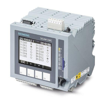
Interfaces and Circuitry Position of the Interfaces on the Housing The interfaces are positioned on the SICAM CMIC housing according to their use. Interfaces on the top of the housing Communication X2: RS-232 X3: RS-485 X1: Ethernet Interfaces on the... - Page 49 Interfaces and Circuitry Interfaces on the bottom of the housing DI-8100 X31 to X32 DO-8203 X21 to X24 Power Supply PS-8630 X12 to X13 SICAM RTUs, User Manual SICAM CMIC DC8-001-2.09, Edition 08.2016...
-
Page 50: Pin Assignment
DIN rail. This shield clamping should be done close to the system. Remote station CMIC DIN rail Note The assignment of X3 is independent whether a termination is existing or not (termination = resistance that is connected through parameter in the firmware). SICAM RTUs, User Manual SICAM CMIC DC8-001-2.09, Edition 08.2016... - Page 51 COM IN 10…………………… common/supply of group 1 OUT D00 to D07…………… make contact outputs 0 to 7 COM OUT D00 to D07…….. common (root) outputs 0 to 7 BAT+/-………………………… input voltage AUX V0+/-……………………. voltage distribution SICAM RTUs, User Manual SICAM CMIC DC8-001-2.09, Edition 08.2016...
-
Page 52: Block Diagrams And External Circuitry
Digital Outputs PS-8630 DI-8100 Element CP-8000 DO-8203 X21 X22 2.3.2 Power Supply Module (PS-8630) PS-8630 5 V / 12 V intermediate circuit galvanical insulation Self resetting fuse (PTC) Contact wetting 24/60 VDC SICAM RTUs, User Manual SICAM CMIC DC8-001-2.09, Edition 08.2016... -
Page 53: Master Control Module (Cp-8000)
IP 1 IP 2 Blackfin FPGA Processor RS-232 RS-485 (2-wire) RS-422 (4-wire) Note X1 and X4 are alternatively 1 Ethernet interface duplicated via an internal switch or 2 independent Ether- net interfaces. SICAM RTUs, User Manual SICAM CMIC DC8-001-2.09, Edition 08.2016... -
Page 54: Digital Inputs (Di-8100)
Interfaces and Circuitry 2.3.4 Digital Inputs (DI-8100) The following circuitry variants are examples, and do not relate exclusively to the depicted inputs/outputs. DI-8100 Controller galvanical insulation PS-8630 AUX VO+/- SICAM RTUs, User Manual SICAM CMIC DC8-001-2.09, Edition 08.2016... -
Page 55: Digital Outputs (Do-8203)
Further information see section 6.2.3, Behavior of the Process Outputs upon Startup and Failure. 2.3.5.1 1 and 2-pole Circuitry DO-8203 Controller 1-pole with pole with 2-pole switched plus switched m inus SICAM RTUs, User Manual SICAM CMIC DC8-001-2.09, Edition 08.2016... -
Page 56: 1½-Pole Circuitry
Interfaces and Circuitry 2.3.5.2 1½-pole Circuitry DO-8203 Controller 1,5-pole *) no galvanical insulation between the relay common and COM OUT D06 SICAM RTUs, User Manual SICAM CMIC DC8-001-2.09, Edition 08.2016... -
Page 57: Cables For External Communication Connections
Interfaces and Circuitry Cables for External Communication Connections SICAM CMIC provides 4 communication interfaces (2x Ethernet TCP/IP, 1x serial RS-232, 1x serial RS-485) to external data transmission facilities. Depending on the kind of the selected communication type, different connection cables are... -
Page 58: Cable For Direct Rs-232 Connection To Another Au
*) in case of a SICAM CMIC or EMIC remote station it is necessary to connect CTS and GND Note By connecting PIN 5 and PIN 8 SICAM CMIC recognizes if a communication unit or SICAM TOOLBOX II is connected. SICAM RTUs, User Manual SICAM CMIC... -
Page 59: Modem Cable For Dial-Up Traffic (Analog)
Interfaces and Circuitry 2.4.2 Modem Cable for Dial-Up Traffic (Analog) Wiring SICAM 9-pol. DSUB CMIC female X2:1 X2:2 X2:3 X2:4 X2:5 X2:6 X2:7 X2:8 X2:9 AUX V0+ AUX V0- (12/24V) TxRx+ TxRx- SICAM RTUs, User Manual SICAM CMIC DC8-001-2.09, Edition 08.2016... -
Page 60: Modem Cable For Dial-Up Traffic (Isdn)
2.4.3 Modem Cable for Dial-Up Traffic (ISDN) Wiring SICAM 9-pol. DSUB CMIC female X2:1 X2:2 X2:3 X2:4 X2:5 X2:6 X2:7 X2:8 X2:9 Shield Shield AUX V0+ AUX V0- (12/24V) Shield Shield SICAM RTUs, User Manual SICAM CMIC DC8-001-2.09, Edition 08.2016... -
Page 61: Modem Cable For Dial-Up Traffic (Gsm, Sms Sender/Receiver)
Interfaces and Circuitry 2.4.4 Modem Cable for Dial-Up Traffic (GSM, SMS Sender/Receiver) Connection between SICAM CMIC and Modem (MC Technologies MC55iw or Cinterion MC52iT). The modem ist supplied with power externally. Wiring Modem 9-pol. Cinterion DSUB female Shield Shield 6-pol. - Page 62 Interfaces and Circuitry SICAM RTUs, User Manual SICAM CMIC DC8-001-2.09, Edition 08.2016...
-
Page 63: Preparing The Engineering
Connecting Engineering PC with the Target Device ........75 Interaction with the Engineering Tool .............. 88 This chapter describes with which methods the system SICAM CMIC can be parameterized and programmed, and which prerequisites must be fulfilled thereto. SICAM RTUs, User Manual SICAM CMIC... -
Page 64: Engineering Tools
(diagnosis, process display) can be used in this case. Note SICAM CMIC is delivered ex factory with an equipped SD card and a default web parameterization. At the moment that you load SICAM TOOLBOX II parameters, the access via SICAM WEB is only read- ing. -
Page 65: Software For The Engineering
The toolsets are also available as “Light” version. With this version, the engineering is limited to maximal 100 system elements and 2000 data points. The toolsets are available individually. You find information and updates for the individual toolsets, as well as numerous licences, on the website http://www.siemens.com/sicam. Document Item number... -
Page 66: Prerequisites
Information thereto reside within a permanently updated List of PC preference types. Should that be not at your disposal, please consult your contact person at Siemens. For the installation of the SICAM TOOLBOX II the following preconditions are required: ·... -
Page 67: Sicam Web
Apple Safari ® support.apple.com Opera Software Opera ® www.opera.com Note When addressing SICAM CMIC via other web browsers, a warning appears in the logon mask. 3.2.2.1 Prerequisites For SICAM WEB the following operating systems are supported: Operating system Hardware PC, Notebook Microsoft Windows 7 ®... -
Page 68: Program Webcmic
The executable file WEBcmic.exe must be stored locally on the engineering PC. For a conven- ient launching you can create a shortcut on the taskbar of the engineering PC. With the program WEBcmic you can · find SICAM CMIC systems connected in a network · assign an IP address to a target device ·... -
Page 69: Loadable Firmwares
For the performing of the respective functions, a special firmware is provided for each system element. The functionality of each system element is adjustable by means of parameters. As a partner of Siemens, you are able to download all the code revisions for your system as loadable binary files via the website http://www.siemens.com/sicam: ·... -
Page 70: Integrated Protocol Snmp
Preparing the Engineering Integrated Protocol SNMP SICAM CMIC supports the protocol SNMP Agent (version 2 and version 3). For the engineer- ing of the SNMP protocol you need to get MIB files and a MIB browser. 3.4.1 Download of the SICAM CMIC MIB-Files MIB-files can be downloaded from the website http://www.siemens.com/sicam:... -
Page 71: Display Of Snmp-Variables In Mib-Browser
Preparing the Engineering 3.4.3 Display of SNMP-Variables in MIB-Browser Example 1: SNMP variable plant Example 2: SNMP variable classInternal. SICAM RTUs, User Manual SICAM CMIC DC8-001-2.09, Edition 08.2016... - Page 72 Preparing the Engineering Example 3: SNMP variable sysUpTime. Example 4: SNMP variable ipInReceives. SICAM RTUs, User Manual SICAM CMIC DC8-001-2.09, Edition 08.2016...
-
Page 73: Sd Card
Preparing the Engineering SD Card For the storage of engineering data SICAM CMIC needs the following SD card. This resides in the slot at the front of the housing. Designation Item number/MLFB SD card up to 32 GB CC6-095 Temperature range up to -25°C... -
Page 74: Interfaces For The Communication
Furthermore, X1 and X4 can be operated via 2 independent IP addresses, see appendix For the transmission of engineering data to a system SICAM CMIC, the engineering PC must be connected with the target device, and a suitable SD card must be equipped in the target device. -
Page 75: Connecting Engineering Pc With The Target Device
Connecting Engineering PC with the Target Device 3.7.1 SICAM TOOLBOX II Before parameters can be loaded via the SICAM TOOLBOX II into SICAM CMIC, the follow- ing steps must be performed: · Insert a suitable SD card into the target device (if not present) ·... -
Page 76: Serial Connection Via Telecommunication Facilities
PC and target device are connected via a network with a standard patch cable with (RJ45 connector). Ethernet TCP/IP 60870-5-104 Standard patch cable SICAM CMIC SICAM TOOLBOX II TOOLBOX II Revision: License Pak: PO K Version 5 | Siemens AG RS-232 O H2 RS-485 O H3 SICAM RTUs, User Manual SICAM CMIC DC8-001-2.09, Edition 08.2016... -
Page 77: Lan/Wan Connection Via Serial Interface And Terminalserver
PC and target device are connected via a network and a terminalserver (DSUB9 connector). Ethernet TCP/IP 60870-5-104 Terminal Server Standard patch cable Direct cable SICAM CMIC SICAM TOOLBOX II TOOLBOX II R evis ion: License Pak: Version 5 | Siemens AG RS-232 RS-485 SICAM RTUs, User Manual SICAM CMIC DC8-001-2.09, Edition 08.2016... -
Page 78: Remote Connection Via Further Sicam Rtus Automation Unit(S)
TOOLBOX II Revisi on: License Pak: Version 5 | Siemens AG Communication interface CM-1820 TOOLBOX connection cable Automation/telecontrol network (IEC 60870-5-101/104) Communication interface LK 1 RS-232 RS-485 LK 4 SICAM CMIC SICAM RTUs, User Manual SICAM CMIC DC8-001-2.09, Edition 08.2016... -
Page 79: Sicam Web
Preparing the Engineering 3.7.2 SICAM WEB Before SICAM CMIC can be parameterized via SICAM WEB, the following steps must be per- formed: · Insert a suitable SD card with the current firmware codes into the target device (if not pre- sent) ·... -
Page 80: Point-To-Point Connection Via Ethernet Interface
Preparing the Engineering 3.7.2.1.2 Point-to-Point Connection via Ethernet Interface The parameterization via point-to-point is suitable if the engineering PC and SICAM CMIC are not operated in a network. PC and target device are connected with a cross connected patch cable via the Ethernet inter- face (RJ45 connector). -
Page 81: Communication With The Target Device
The establishing of a communication connection between engineering PC and the target device takes place via adjustable IP addresses. For the initial parameter setting of SICAM CMIC, default IP addresses are available. These are specific for the respective physi- cal connection. -
Page 82: Point-To-Point Connection Via Serial Interface
Connection setup via SICAM WEB Configure IP Address for Engineering PC For the parameter setting the IP addresses predefined in SICAM CMIC are used. Thereby the web server of the target device assignes automatically the IP address 172.16.0.2 to the engineering PC, if this is configured for the automatic acceptance of an IP address. -
Page 83: Point-To-Point Connection Via Ethernet Interface
Connection via SICAM WEB Start the web browser and enter the IP address of your target device (172.16.0.3) in the address bar. You find the further information in chapter 5, Engineering via SICAM WEB. SICAM RTUs, User Manual SICAM CMIC DC8-001-2.09, Edition 08.2016... -
Page 84: Lan/Wan Connection Via Ethernet Interface
Connection setup via SICAM WEB Configure IP Address with WEBcmic With operation in a network an unambiguous IP address must be assigned to SICAM CMIC. The assignment of the IP address is dependent on the subnet mask used in the network. - Page 85 With the firmware CPC80 as of revision09 the setting of an IP address by means of WEBcmic is supported only as long as the default IP address (172.16.0.3) exists in the target device. SICAM RTUs, User Manual SICAM CMIC DC8-001-2.09, Edition 08.2016...
- Page 86 . After the startup, the respective target device can be addressed by the webbrowser. Note The writing of the IP address with WEBcmic is also possible locally via the serial interface. SICAM RTUs, User Manual SICAM CMIC DC8-001-2.09, Edition 08.2016...
- Page 87 WEB. Note According to the parameterization in SICAM CMIC you have to enter a http or https –address in the browser to establish the connection. During the first time connetion establishment via https there is a check if the corresponding security certifi- cate is installed.
-
Page 88: Interaction With The Engineering Tool
Interaction with the Engineering Tool 3.8.1 SICAM TOOLBOX II For the engineering of SICAM CMIC serves the SICAM TOOLBOX II installed on the engi- neering PC. Before you start with the engineering, the predefined configuration parameters of the SICAM TOOLBOX II must be checked and changed, if necessary (see section 4.1.1, Presets). -
Page 89: Sicam Web
3.8.2 SICAM WEB For the engineering of SICAM CMIC serves the web browser installed on the engineering PC. The web browser shows HTML sites provided by the integrated web server of SICAM CMIC. The parameterization is performed online in the target device. - Page 90 By clicking on this button you are able to return to the Dashboard from each website in SICAM WEB. Navigation By clicking on this button you are able to select the desired area from a drop-down list from each website in SICAM WEB. SICAM RTUs, User Manual SICAM CMIC DC8-001-2.09, Edition 08.2016...
-
Page 91: General Buttons
Thus, you can see at a glance whether there is a modification of parameters (button enabled) or not (button disabled). For the user name guest the button is always disabled. SICAM RTUs, User Manual SICAM CMIC DC8-001-2.09, Edition 08.2016... - Page 92 You have the possibility to specifically search for certain information: ─ In the field Filter enter the word (or a part of it) to search for ─ Click the cross to reset the filter SICAM RTUs, User Manual SICAM CMIC DC8-001-2.09, Edition 08.2016...
-
Page 93: Parameter Entry
In the table, click on a value of a parameter · For showing/hiding the description of the selected parameter, click on the yellow bar locat- ed to the right of the work area SICAM RTUs, User Manual SICAM CMIC DC8-001-2.09, Edition 08.2016... - Page 94 Press ESC key if you want to restore the previous valid value In case of table parameters, there is the possibility to define new rows with parameters. The procedure for that is described subsequently. SICAM RTUs, User Manual SICAM CMIC DC8-001-2.09, Edition 08.2016...
- Page 95 Click on the symbol for delete This is how to fill an amount of table parameters automatically: Example 1: · Select the desired column · Enter the start value and the increment, then click on SICAM RTUs, User Manual SICAM CMIC DC8-001-2.09, Edition 08.2016...
- Page 96 The start value must be within the permitted range, the increment must be always a number. Example 2: · Select the desired column · Enter the start value and the increment, then click on The selected column is now filled according to the input: SICAM RTUs, User Manual SICAM CMIC DC8-001-2.09, Edition 08.2016...
-
Page 97: Show Expert Parameters
When activating the checkbox Show all parameters the expert parameters get visible: The state of the checkbox is maintained during the current session. When logging on again, the state of the checkbox is deactivated. SICAM RTUs, User Manual SICAM CMIC DC8-001-2.09, Edition 08.2016... -
Page 98: Restart Request
The language of the GUI corresponds to the language settings of your browser. If the browser language is not supported, English will be used as the standard language. Additionally, you have the option of installing language packs, see Install Language Package. SICAM RTUs, User Manual SICAM CMIC DC8-001-2.09, Edition 08.2016... -
Page 99: Navigation With The Web Browser
If you leave the page, the web browser is closed, the session is automatically terminated, and unsaved data is lost · If you stay on the page, you can continue workoing with the latest entered values SICAM RTUs, User Manual SICAM CMIC DC8-001-2.09, Edition 08.2016... -
Page 100: Session Monitoring
Logon If you open a new browser window or a new browser tab: You are already logged on at SICAM CMIC (succesful logon). The logon dialog will appear after opening a new browser window or a new browser tab, after entering the IP address of the device and after a successful connection establishment. -
Page 101: Exceptions With Engineering Via Sicam Web
ASCII format can be loaded into the target device. · Test of the application program Offline simulation of the application program is not possible. A simplified online test (state display, forcing of a selectable signal) is available. SICAM RTUs, User Manual SICAM CMIC DC8-001-2.09, Edition 08.2016... - Page 102 Preparing the Engineering SICAM RTUs, User Manual SICAM CMIC DC8-001-2.09, Edition 08.2016...
-
Page 103: Engineering Via Sicam Toolbox Ii
This chapter is a guideline for the work with the SICAM TOOLBOX II. You find the detailed in- structions for the work with the tools of the SICAM TOOLBOX II in the SICAM TOOLBOX II Online Help and in the CAEx plus Online Help. SICAM RTUs, User Manual SICAM CMIC DC8-001-2.09, Edition 08.2016... -
Page 104: Telecontrol
Topology test Acqusition of physically connected automation units in a SICAM RTUs automation network Diagnosis Read detailed information generated by the self monitoring Read decentral archive Chronological display of parameterized events SICAM RTUs, User Manual SICAM CMIC DC8-001-2.09, Edition 08.2016... - Page 105 (csv file) selection AU services document HW documentation configuration assembly technical documentation preview spreadsheet document system technique selection AU parameters print spreadsheet SICAM RTUs, User Manual SICAM CMIC DC8-001-2.09, Edition 08.2016...
-
Page 106: Presets
You find the details thereto in the SICAM TOOLBOX II Online Help, chapter “TOOLBOX II Presets”, section “User/Role Administration”. Note All operation and test functions of SICAM CMIC described in this manual are generally applicable for the admin role available in the SICAM TOOLBOX II. Note From SICAM TOOLBOX II V5.11 it is possible to create domain users. -
Page 107: Password
Logout ). You can continue to operate tools that are still active, but the activation of tools re- quires another login. If all tools are quit without logout, the user will remain logged in unless a logout from the Toolbox PC or Toolbox Server takes place. SICAM RTUs, User Manual SICAM CMIC DC8-001-2.09, Edition 08.2016... -
Page 108: Change Password
TOOLBOX II with the tool “Master Data Update”. You find further information in section 6.5.1.2, Importing Master Data into the SICAM TOOLBOX You find information on firmware files in section 3.3, Loadable Firmwares. SICAM RTUs, User Manual SICAM CMIC DC8-001-2.09, Edition 08.2016... -
Page 109: Configuration And Settings For Telecontrol
The user’s guide of the OPM II can be found in the SICAM TOOLBOX II Online Help, chapter “OPM II”. The description of the system-technical and process-technical settings can be found in the manual SICAM RTUs Common Functions System and Basic System Elements, chapter “Telecontrol”. SICAM RTUs, User Manual SICAM CMIC DC8-001-2.09, Edition 08.2016... -
Page 110: Hardware Configuration
The configuration takes place with the tool “OPM II” via the menu items Tools | Systemtechnik and Tools | Library Overview . By dragging the system elements of the system SICAM CMIC from the Library Overview onto the respective target device in the system technique, the corresponding system elements are added with default parameters. -
Page 111: System-Technical Settings
Software data points By means of the context menu of a hardware pin or software data point, selection Edit image , you get directly to the process-technical settings of the respective signal. SICAM RTUs, User Manual SICAM CMIC DC8-001-2.09, Edition 08.2016... -
Page 112: Process-Technical Settings
A type is defined respectively for objects, that have the same features (examples: feeder, cir- cuit breaker, disconnector). You find the instruction to define the different types in the SICAM TOOLBOX II Online Help, chapter “OPM II”, section “Types”. SICAM RTUs, User Manual SICAM CMIC DC8-001-2.09, Edition 08.2016... -
Page 113: Images
The assignment of a process signal to a hardware pin or software data point in the system technique takes place by means of assignment (alternatively automatical or manual). You find the instruction thereto in the SICAM TOOLBOX II Online Help, chapter "Parameter Documen- tation", section “Assign”. SICAM RTUs, User Manual SICAM CMIC DC8-001-2.09, Edition 08.2016... -
Page 114: Decentral Archiving (Dear)
Interface to Elcad · Telecontrol function ─ System-technical configuration ─ Process-technical settings You find the details thereto in the SICAM TOOLBOX II Online Help, chapter “OPM II”, section “System Technique”, section “Documentation”. SICAM RTUs, User Manual SICAM CMIC DC8-001-2.09, Edition 08.2016... -
Page 115: Hardware Configuration
The generation of the file takes place via selection of the menu Destination systems | SICAM 1703… | SICAM 1703 Transformer. You find the details thereto in the SICAM TOOLBOX II Online Help, chapter “OPM II”, section “Elcad”. SICAM RTUs, User Manual SICAM CMIC DC8-001-2.09, Edition 08.2016... -
Page 116: Telecontrol Function
SD card of the target device: · Configuration parameters · System-technical parameters · Process-technical parameters (if they have been transformed previously) · Application program (if code has been generated previously) SICAM RTUs, User Manual SICAM CMIC DC8-001-2.09, Edition 08.2016... -
Page 117: Parameter Comparison
You can select an automation unit and start the comparison via the menu Parameter | Comparison Aus <-> Toolbox ). For each selected automation unit appears the indication whether the parameters are current or not current. SICAM RTUs, User Manual SICAM CMIC DC8-001-2.09, Edition 08.2016... -
Page 118: Test Functions
You find the instruction for this test function in the SICAM TOOLBOX II Online Help, chapter "Service Programs“, section "Data Flow Test". You find further information in the manual SICAM RTUs Common Functions System and Basic System Elements, chapter "System Services", section "Data Flow Test". SICAM RTUs, User Manual SICAM CMIC DC8-001-2.09, Edition 08.2016... -
Page 119: Simulation Of Spontaneous Data Points
You find the instruction for this test function in the SICAM TOOLBOX II Online Help, chapter "Service Programs“, section “Service Programs”section "Topology Test". SICAM RTUs, User Manual SICAM CMIC DC8-001-2.09, Edition 08.2016... -
Page 120: Displaying Decentral Archive (Dear)
You can save the displayed records of DEAR in a file (Format .csv) on the engineering PC. You find the information thereto in the SICAM TOOLBOX II Online Help, chapter “OPM II”, section “System Technique”, “General”, “SICAM RTUs”, “Decentral Archive Display”. SICAM RTUs, User Manual SICAM CMIC DC8-001-2.09, Edition 08.2016... -
Page 121: Automation
CAEx plus load parameters load code select AU OPM II ONLINE simulation (test of function chart test function select AU logic in the target chart CAEx plus system) Online Test SICAM RTUs, User Manual SICAM CMIC DC8-001-2.09, Edition 08.2016... -
Page 122: Creating A Function Diagram
SICAM CMIC can be used. Signals from the signal list From the signal list only signal types supported by SICAM CMIC can be used in the type instance (for instance the message with TI 38 – “protection event” is not allowed). The check is performed via the data type of the signal. -
Page 123: Configuring External Signals
“CAEx plus”. You find the most important characteristic values (limits) for the creation of the open-/closed- loop control function in the SICAM CMIC System Description, chapter “Technical Specifications of the Modules”, section “Master Control Modules”. You find the technical details for the processing of the open-/closed-loop control function and its partial functions in the manual SICAM RTUs Common Functions System and Basic System Elements, chapter “Automation”, section “Restricted Open-/Closed-Loop Control Function”,... - Page 124 Engineering via SICAM TOOLBOX II Function Diagram (Example) SICAM RTUs, User Manual SICAM CMIC DC8-001-2.09, Edition 08.2016...
-
Page 125: Program Code Generation
Via the menu Tools | Error-state viewer you can activate the notification display of the code generation. There are recorded common notifications (as for instance information about the occupied storage space for code and variables), as well as detected errors in detail. SICAM RTUs, User Manual SICAM CMIC DC8-001-2.09, Edition 08.2016... -
Page 126: Documentation
It is executed via the respective context menu Cross-references . You find the details thereto in the CAEx plus Online Help, chapter “Basics”, section “Default Operating Elements”, section “Commands of the Pop-Up Menus”. SICAM RTUs, User Manual SICAM CMIC DC8-001-2.09, Edition 08.2016... -
Page 127: Open-/Closed-Loop Control Function
System and Basic System Elements, chapter “Automation”, section “Open-/Closed-Loop Con- trol Function”, “Loading of Application Program (Reload)”. You find the instruction for the operation in the SICAM TOOLBOX II Online Help, chapter “Service Programs”, section “Parameter Loader”. SICAM RTUs, User Manual SICAM CMIC DC8-001-2.09, Edition 08.2016... -
Page 128: Test Functions
Read and write variables The technical description of the online test function can be found in the manual SICAM RTUs Common Functions System and Basic System Elements, chapter "Automation", section "Online Test". SICAM RTUs, User Manual SICAM CMIC DC8-001-2.09, Edition 08.2016... - Page 129 With user program running, the simulated value of a variable is statically overwritten. In contrast to this, inputs/outputs are not statically overwritten, rather only with a change to their process image (edge- triggered). With user program stopped, simulated values are retained. SICAM RTUs, User Manual SICAM CMIC DC8-001-2.09, Edition 08.2016...
- Page 130 Engineering via SICAM TOOLBOX II SICAM RTUs, User Manual SICAM CMIC DC8-001-2.09, Edition 08.2016...
-
Page 131: Engineering Via Sicam Web
Telecontrol ....................132 Automation ....................239 Administrative Functions ................261 This chapter describes how the system SICAM CMIC can be parameterized via SICAM WEB, which possibilities exist for the loading and saving of data, and how an application program can be created. -
Page 132: Telecontrol
SD card is installed in the target device · Target device is switched on · Physical connection to the target device is established · IP addresses for target device and/or engineering PC are configured SICAM RTUs, User Manual SICAM CMIC DC8-001-2.09, Edition 08.2016... -
Page 133: Start And Terminate Session
20 seconds. The session with the web server of the target device has started. As user name administrator you can begin now with the parameter-setting. SICAM RTUs, User Manual SICAM CMIC DC8-001-2.09, Edition 08.2016... -
Page 134: Rights Of The Users
ü ü Display I/O status ü Force outputs ü ü Diagnosis Note No more than 1 administrator and 2 guest can be logged in to the device at the same time. SICAM RTUs, User Manual SICAM CMIC DC8-001-2.09, Edition 08.2016... -
Page 135: Logoff
After the initial logon you should define some basic settings for working with SICAM WEB. The basic settings are necessary to logon to the target device and security · Authentication procedure · Change web server password · Set IP addresses · Enable optional “Autoconfiguration” SICAM RTUs, User Manual SICAM CMIC DC8-001-2.09, Edition 08.2016... -
Page 136: Authentication Procedure
This is the default mechanism. After entering the login credentials and login attempt, SICAM CMIC compares these credentials with the locally stored credentials: · If the comparison is successful, SICAM CMIC returns the specific user role · If the comparison is not successful, the logon fails SICAM RTUs, User Manual SICAM CMIC DC8-001-2.09, Edition 08.2016... -
Page 137: Authentication Via External Service
− If the comparison is not successful, the logon fails ─ If the fallback option is not enabled, the logon fails Configuration with RADIUS Server The IP address of the RADIUS server must match with the setting in SICAM CMIC (parameter Radius server IP address). -
Page 138: Change Web Server Password
Change Web Server Password The change of the password for the web server takes place in the directory tree under SICAM CMIC | Master module | Network settings | IP address | HTTP web server. After the initial logon, an indication appears that a password must be defined. The password is required in order to protect the respective target device against unauthorized access. -
Page 139: Differentiation Secure/Non-Secure Passwords
Differentiation Secure/Non-Secure Passwords The selection of the secure password storage resides in the directory tree under SICAM CMIC | Master module | Network settings | Security (the checkbox Show all parameters must be activated). All passwords can be stored in the target device in a secure manner. Thereto the passwords are stored irreversibly encrypted in a location not accessible by unauthorized persons. - Page 140 When opening the dialog both input fields are always empty and the checkbox Unhide characters is deactivated. You must enter the same password in both input fields (new password and verify new pass- word). Each entered character is shown as an asterisk. Example: SICAM RTUs, User Manual SICAM CMIC DC8-001-2.09, Edition 08.2016...
- Page 141 Switching Between Secure and Non-Secure Password Secure passwords and non-secure passwords are stored separately in SICAM CMIC. If you enter a non-secure password in the target device, and you activate the secure pass- word storage afterwards, you must enter a new secure password.
-
Page 142: Set Ip Addresses
The IP address set via SICAM WEB is only relevant without use of a DHCP server (parameter = NO). Autoconfiguration With use of a DHCP server SICAM CMIC receives the the IP address automatically. Further details see 5.1.2.5, Autoconfiguration (restricted operation mode). -
Page 143: Access Options For The Engineering Pc In Operation
Irrelevant Irrelevant = <set value> (X4) SICAM CMIC> Point-to-Point 172.16.0.1 172.16.0.2 (assigned by Irrelevant Irrelevant (X2) SICAM CMIC) applies only if 2 IP addresses (independent ports) Mode of the Ethernet ports SICAM RTUs, User Manual SICAM CMIC DC8-001-2.09, Edition 08.2016... -
Page 144: Autoconfiguration
Engineering via SICAM WEB 5.1.2.5 Autoconfiguration SICAM CMIC provides the option of being configured automatically by means of a complete autoconfiguration file via DHCP service. The autoconfiguration file is a previously generated SICAM CMIC backup (see 5.3.2, Saving Device Settings). - Page 145 FTP. The TFTP server must provide the configuration file of the respective SICAM CMIC target de- vice.
- Page 146 Depending on the setting of the “Lease Time” on the DHCP server, the configuration can be updated. If the same file name is given, the target device keeps its settings. If another name is given, the file is downloaded again and the settings are accepted. SICAM RTUs, User Manual SICAM CMIC DC8-001-2.09, Edition 08.2016...
-
Page 147: Common Settings
With use of an application program, the address can be set which uses the application pro- gram for the generation of its data. The setting thereto resides under SICAM CMIC | Master module | AU common settings | common address of ASDU (CASDU). -
Page 148: Topology
Failure Behavior upon Fault The setting for the failure behavior resides in the directory tree under SICAM CMIC | Master module | BSE common settings. The occurance of a heavy fault can lead to an undefined state in the processing of the firm- ware on the master control element. -
Page 149: Parameterize Hardware Configuration
You find the instruction thereto in section 5.3.4, Firmware. The protocol elements and I/O modules supported by SICAM CMIC are listed in the SICAM CMIC System Description. The hardware configuration overview resides in the directory tree under SICAM CMIC. - Page 150 The target device performs a restart, refer to Restart device. During startup, the settings are stored on the SD card and the configuration pages for the se- lected system elements are built in SICAM WEB. SICAM RTUs, User Manual SICAM CMIC DC8-001-2.09, Edition 08.2016...
-
Page 151: Protocol Elements
After the startup the configured protocol elements appear in the directory tree under SICAM CMIC | Master module | PRE <0…3>: <protocol name>. The parameterization takes place for each protocol in the settings page. The parameters of newly identified protocols are assigned with their default values. -
Page 152: Peripheral Element
5.1.4.3 Peripheral Element In SICAM CMIC you can equip 1 peripheral element. The hardware for the peripheral element as well as 2 internal I/O modules are integrated on the master control element. With use of external I/O modules, these must be connected (mechanically) to the target de- vice before the engineering in SICAM WEB. - Page 153 SICAM RTUs Ÿ SICAM I/O Modules and SICAM RTUs Ÿ SICAM TM I/O Modules. Please pay attention to the configuration notes and rules for the equipment of I/O modules in the SICAM RTUs Ÿ SICAM CMIC System Description, chapter “Overview”, section “Architec- ture” | “Peripheral Element” | “I/O Modules”.
-
Page 154: Configuring Time Management
5.1.5 Configuring Time Management · Menu Home | Settings 5.1.5.1 Time Synchronization The internal clock of SICAM CMIC serves for the time tagging of generated data · from the periphery · from the optional Open/closed-loop control function · for the records in the diagnosis The resolution of the time tag is 1 ms. -
Page 155: Time Synchronization With Multi-Point Traffic
5.1.5.1.1 Time Synchronization with Multi-Point Traffic The time is sent from a central station (time master) to SICAM CMIC. The time master must synchronize at least each 60 s, in order that the minimum resolution of 10 ms is achieved. -
Page 156: Daylight Saving Time Rule
NTP Server The settings for the NTP server reside in the directory tree under SICAM CMIC | Master module | Network settings | NTP time synchronization server (the checkbox Show all parameters must be activated). If further devices that require a time synchronization by means of NTP are connected with a target device, these devices can be supplied also with the time via the function NTP Server. -
Page 157: Local Time Setting
Set a checkmark in the checkbox Enter manually · Edit the fields Date, Time and Time zone as you wish · Click on the button in order to load the defined time into the target device SICAM RTUs, User Manual SICAM CMIC DC8-001-2.09, Edition 08.2016... -
Page 158: Configure Communication
5.1.7.1 Common Settings The common settings of the communication reside in the directory tree under SICAM CMIC | Master module | Communication | Common settings (the checkbox Show all parameters must be activated). Periodical Transfer of User Data Each user data message can be assigned a periodical level (only in the case of datapoint- specific routing). -
Page 159: Physical Interface For The Communication
5.1.7.2 Physical Interface for the Communication SICAM CMIC can communicate simultaneously via up to 4 physical interfaces. For each con- figured protocol element an interface must be assigned exclusively. The assignment of the interface for each protocol element resides in the directory tree under... -
Page 160: Select Transmission Facility
With usage of 2 independent Ethernet interfaces, the interface X1 or X4 must be assigned for protocol elements via Ethernet. The assignment of the LAN interface takes place in the directory tree under SICAM CMIC | Master module | Network settings | IP addresses | Interface mapping (pa- rameter Interface PRE<0…3>. -
Page 161: Settings Of The Messages
· Monitoring ACTCON Transmission with/without time tag The information objects supported by SICAM CMIC can be transmitted to the control center either with time tag or without time tag. The definition happens selectively for each type identi- fication. You find the parameters thereto in the subdirectory Transmission with/without time tag. -
Page 162: Data Management And Priority Control
Engineering via SICAM WEB The settings on the protocol element reside in the directory tree under SICAM CMIC | Master module | PRE <0…3>: | Advanced settings | <protocol name> IEC 60870-5-101 (applies only for end-end traffic and multi-point traffic). -
Page 163: Decentral Archiving
The configuration of the archive resides in the directory tree under SICAM CMIC | Master module | Decentral archiving (the checkbox Show all parameters must be activated). - Page 164 The addresses that are calculated automatically are not shown in the web browser. If such an address is set in the parameterization of the telecontrol function within SICAM MIC, an error message occurs on at- tempt to apply. SICAM RTUs, User Manual SICAM CMIC DC8-001-2.09, Edition 08.2016...
-
Page 165: Configure Periphery And Internal Signals
The firmware of the peripheral element provides the functions for the technological prepara- tion of the inputs/outputs (signal preprocessing, signal postprocessing). SICAM CMIC supports 2 internal and up to 6 external I/O modules. The following types can be used: ·... - Page 166 · Enter the desired number of rows (each row corresponds to 1 signal) · Cick on the button In the following example 2 new signals have been created: SICAM RTUs, User Manual SICAM CMIC DC8-001-2.09, Edition 08.2016...
- Page 167 Common Functions System and Basic System Elements, chapter "System Services", section "Data Flow Control". Type Identification The description of the different type identifications (TI) resides in the manual SICAM RTUs Common Functions System and Basic System Elements, Appendix "Message Formats". SICAM RTUs, User Manual SICAM CMIC DC8-001-2.09, Edition 08.2016...
-
Page 168: Duplicate And Delete Rows
With this example the signals SI_0 and SI_1 are duplicated twice each. Define Name, IEC address and type identification for the new signals This is how you can delete lines: · Mark the relevant row · Click on the button SICAM RTUs, User Manual SICAM CMIC DC8-001-2.09, Edition 08.2016... -
Page 169: Automatic Filling And Automatic Incrementation
· Enter the value 1 in the input field step · (Fill selected) Click on the button Result: The IOA1 of all subsequent signals is consecutively increased by the value 1. SICAM RTUs, User Manual SICAM CMIC DC8-001-2.09, Edition 08.2016... -
Page 170: Assign Signals To The Master Control Element (Master Module)
The assigned signals are now listed in a table under the tab Assignment. Note You can enlarge the work area by clicking on the bars right and/or left beside the work area. SICAM RTUs, User Manual SICAM CMIC DC8-001-2.09, Edition 08.2016... - Page 171 All signals of the selected category (on the selected system element) are displayed listed in the table. Thereby, the signal name, the message address and the type identification are tak- en over from the work area for the signal generation. SICAM RTUs, User Manual SICAM CMIC DC8-001-2.09, Edition 08.2016...
-
Page 172: Configurable Logging And Display Of Signal States
All signals assigned to that categorie are displayed. · Select which signals are to be logged as an event · Enter the texts for names and states for the desired signals Description of the parameters see Process control. SICAM RTUs, User Manual SICAM CMIC DC8-001-2.09, Edition 08.2016... - Page 173 In this example, 3 binary information items are assigned to the group positions 1, 3 and 4. When position 2 is not used, at this place an empty line will be displayed on the LCD (see 6.1.2.4.5, Cockpit). Description of the parameters see Process value digital. SICAM RTUs, User Manual SICAM CMIC DC8-001-2.09, Edition 08.2016...
- Page 174 2, 3 and 4 are not used, at this place an empty line will be displayed on the LCD (see 6.1.2.4.5, Cockpit). · Enter the measuring range for the value adaptation · Enter the number of decimal places for the display Description of the parameters see Process value analog. SICAM RTUs, User Manual SICAM CMIC DC8-001-2.09, Edition 08.2016...
- Page 175 The definition of the groups happens in the menu Home | Settings. · Select the node SICAM CMIC | Master Module | Process information and control | Process groups. For the process display in the cockpit, 32 freely definable groups are available.
-
Page 176: Parameters With Assignment On The Master Control Module
· Smoothing factor · Lower limit for transmission of measured values · Upper limit for transmission of measured values · Activation parameters for measured values Interrogation-group General interrogation (group 1…16; none) SICAM RTUs, User Manual SICAM CMIC DC8-001-2.09, Edition 08.2016... - Page 177 The data point is displayed in the cockpit on this position (1…256) pva_X_0% Value adaptation: Lower limit of the used measuring range in the external (protocol specific) format. The corresponding internal value is defined at Y_0%. SICAM RTUs, User Manual SICAM CMIC DC8-001-2.09, Edition 08.2016...
- Page 178 · 245...255 = reserve for further BSE func- tions · Positive edge Edge_(PRE) · Negative edge · State (0 = function, 1 = function + 1) PRE_(CM) Protocol element number · PRE0…PRE3 · distribute over multimaster function SICAM RTUs, User Manual SICAM CMIC DC8-001-2.09, Edition 08.2016...
- Page 179 0…99 = selective station unused = single-point-PRE or multi-point- PRE to all remote stations · Data class 1 Data_class · Data class 2 Periodical transfer Selection periodical level or no periodical transfer Event_data SICAM RTUs, User Manual SICAM CMIC DC8-001-2.09, Edition 08.2016...
- Page 180 Inversion NO/YES TI31_Selection OFF/ON Fail_behav Failure behavior Fail_subst_value Substitute value at failure single_object_number · Command state not evaluate Command_state · Command state ON before OFF · Command state OFF before ON SICAM RTUs, User Manual SICAM CMIC DC8-001-2.09, Edition 08.2016...
- Page 181 Source identification basic system element QID-ST Source identification station number if mul- tipoint traffic mode 0…99 if R-SID 0…254. If automatic then the source ID will be learned. QID-SSE Source identification supplementary system element SICAM RTUs, User Manual SICAM CMIC DC8-001-2.09, Edition 08.2016...
-
Page 182: Assigning Signals To The Peripheral Element (I/O Master Module)
· Select the directory SICAM CMIC | Master Module | I/O Master Module · Mark on the right side the signals to be assigned · Click on the button (Assign) The assigned signals are now listed in a table under the tab Assignment. - Page 183 In the dropdown list only those datapoints are offered that are compatible with the processing type and that are not yet in use. HW pins are irrelevant here and therefore not editable. SICAM RTUs, User Manual SICAM CMIC DC8-001-2.09, Edition 08.2016...
- Page 184 · Activate the checkbox Show all parameters if you want to edit expert parameters · Save your changes from time to time, refer to Apply Further steps:Restart device. SICAM RTUs, User Manual SICAM CMIC DC8-001-2.09, Edition 08.2016...
-
Page 185: Parameters With Assignment On The Peripheral Element
0…99 if R-SID 0…254. If automatic then the source ID will be learned. SID-SSE Source identification supplementary system element ACTCON_yes_no Sending of ACTCON and ACTTERM SW_CO_EA – command – error acknowledgement SW_DO_TE-6460 – SICAM RTUs, User Manual SICAM CMIC DC8-001-2.09, Edition 08.2016... -
Page 186: Assigning Signals To The I/O Module
· Select the directory SICAM CMIC | Master Module | I/O Master Module | <0…7>: <mod- ule name> · Mark on the right side the signals to be assigned ·... - Page 187 In the dropdown list only those datapoints are offered that are compatible with the processing type and that are not yet in use. The HW pin is automatically assigned, as soon as you have defined processing type and datapoint of the signal. SICAM RTUs, User Manual SICAM CMIC DC8-001-2.09, Edition 08.2016...
- Page 188 After selection of the processing type, you can now parameterize the relevant signals process- technically. · Activate the checkbox Show all parameters if you want to edit expert parameters · Save your changes from time to time, refer to Apply Further steps:Restart device. SICAM RTUs, User Manual SICAM CMIC DC8-001-2.09, Edition 08.2016...
-
Page 189: Automatic Display Of Signal States
IN D17 of one BI-module as PM input for all modules Attention: Selected module must be a DI module. Flutt_t_stable Flutter suppression: stability time in seconds. 0 = stability time defined through parameter Flutt_t (S) 0.1 to 6553.5 SICAM RTUs, User Manual SICAM CMIC DC8-001-2.09, Edition 08.2016... - Page 190 (S) transm_prompting Transmission prompting. The initiating for the transfer of the latched count can happen through a counter interrogation message (group), through adjustable intervals, or through the function diagramm. (S) SICAM RTUs, User Manual SICAM CMIC DC8-001-2.09, Edition 08.2016...
- Page 191 Source identification basic system element SID-ST Source identification station number if mul- tipoint traffic mode 0…99 if R-SID 0…254. If automatic then the source ID will be learned. SID-SSE Source identification supplementary system element SICAM RTUs, User Manual SICAM CMIC DC8-001-2.09, Edition 08.2016...
-
Page 192: Parameters With Assignment On The Do Module
Attention: Function only active if sync_t = 0. 0.1 to 25.5 RS_outp_same_state_1 Selection of command output and command confirmation, if return state is already end po- sition before output. Attention: only active if RS_mon_t ≠ 0 SICAM RTUs, User Manual SICAM CMIC DC8-001-2.09, Edition 08.2016... - Page 193 · YES: ON is I/O with lower I/O number OFF is I/O with higher I/O number Regulating_command Use as regulating command (S) NO/YES RS_Image Parameter works only with ACP 1703 platform SICAM RTUs, User Manual SICAM CMIC DC8-001-2.09, Edition 08.2016...
- Page 194 Within this time (in sec) the enabling over the syncronisation input must occur on the com- mand. 0 = no syncronisation over syncronisation in- put. Attention: Function only active if sync_t = 0 0.1 to 6553.5 SICAM RTUs, User Manual SICAM CMIC DC8-001-2.09, Edition 08.2016...
- Page 195 Max. time between select and execute (in se- conds). After this time a recent select com- mand is necessary. 0 = no select command is expected (direct command transmission) 0.1 to 102.3 SICAM RTUs, User Manual SICAM CMIC DC8-001-2.09, Edition 08.2016...
- Page 196 Sw_Seq_addtl_com_0 Switching sequence: Select the additional command Sw_Seq_command_seq_1 Switching sequence: output additional com- mand before or after the command Sw_Seq_addtl_com_1 Switching sequence: Select the additional command SICAM RTUs, User Manual SICAM CMIC DC8-001-2.09, Edition 08.2016...
- Page 197 Address of corresponding return state infor- mation (S) 0 to 255 RS_Image_IOA2 Address of corresponding return state infor- mation (S) 0 to 255 RS_Image_IOA3 Address of corresponding return state infor- mation (S) 0 to 255 SICAM RTUs, User Manual SICAM CMIC DC8-001-2.09, Edition 08.2016...
- Page 198 0.1 to 6553.5 RS_Mon_t Return state information monitoring time in seconds (S). 0 = no return state information monitoring 0.01 to 655.35 Command_prolong_t Command prolongation time in seconds (S) 0.01 to 327.67 SICAM RTUs, User Manual SICAM CMIC DC8-001-2.09, Edition 08.2016...
- Page 199 0 = no syncronisation over interlocking 0.1 to 6553.5 RS_Mon_t Return state information monitoring time in seconds (S). 0 = no return state information monitoring 0.01 to 655.35 SICAM RTUs, User Manual SICAM CMIC DC8-001-2.09, Edition 08.2016...
- Page 200 QOC>8 If QOC > 8 (Qualifier of Command) is accept- ed, so all QOC > 8 will be interpreted as QOC = 0 RS_Image Parameter works only with ACP 1703 platform SICAM RTUs, User Manual SICAM CMIC DC8-001-2.09, Edition 08.2016...
- Page 201 ID will be learned. SID-SSE Source identification supplementary system element QOC>8 If QOC > 8 (Qualifier of Command) is accept- ed, so all QOC > 8 will be interpreted as QOC = 0 SICAM RTUs, User Manual SICAM CMIC DC8-001-2.09, Edition 08.2016...
- Page 202 0 = no termination 0 to 6553.5 RS_react_t Information reaction time (S) Pulse command: 0 .. time appropriate to out- put time Persisitent command: 0 .. time appropriate to termination time 0 to 6553.5 SICAM RTUs, User Manual SICAM CMIC DC8-001-2.09, Edition 08.2016...
- Page 203 Engineering via SICAM WEB Processing type Parameter Meaning SW_CO_SYNC_A – – command synchroniza- tion abortion SW_CO_SYNC_R - – command synchroniza- tion is running SW_DO – Software data – point digital output SICAM RTUs, User Manual SICAM CMIC DC8-001-2.09, Edition 08.2016...
-
Page 204: Parameters With Assignment On The Ai Module
Zero range suppression (and check of the plausibility limits) either standard or free parametrizable (S) · standard · free configurable OV_suppr_t OV suppression time in seconds, 0=no OV suppression 0 to 255 SICAM RTUs, User Manual SICAM CMIC DC8-001-2.09, Edition 08.2016... - Page 205 Technological or normalized value of zero range (S) -1000000000000000.000 to 1000000000000000.000 zero_range_a MV_conv Zero range suppression (and check of the plausibility limits) either standard or free parametrizable (S) · standard · free configurable SICAM RTUs, User Manual SICAM CMIC DC8-001-2.09, Edition 08.2016...
- Page 206 Change threshold in % of X_100% (S) AI_T: % of temperature range 0 to 103.00 SW_CT_PDIR – SW_F – software fre- thresh_additive Change threshold in % of X_100% (S) AI_T: quency % of temperature range 0 to 1000.0 SICAM RTUs, User Manual SICAM CMIC DC8-001-2.09, Edition 08.2016...
- Page 207 Change threshold in % of X_100% (S) AI_T: % of temperature range 0 to 1000.0 thresh_uncond Change threshold in % of X_100% (S) AI_T: % of temperature range 0 to 103.00 SICAM RTUs, User Manual SICAM CMIC DC8-001-2.09, Edition 08.2016...
- Page 208 Transformer type transformer_angle Angle between upper and lower side of trans- former 0 to 359 Overrange Definition of the overrange for QDS 'OV' in % of the nominal range of the transformer SICAM RTUs, User Manual SICAM CMIC DC8-001-2.09, Edition 08.2016...
-
Page 209: Parameters With Assignment On The Ao Module
Fail_behav Behavior at failure · keep · Substitute value block Blocking (=not used) (S) NO/YES X_0% Nominal range in the physical unit of the in- put/output (0%) (S) -10.0 to 10.0 SICAM RTUs, User Manual SICAM CMIC DC8-001-2.09, Edition 08.2016... - Page 210 Source identification basic system element SID-ST Source identification station number if mul- tipoint traffic mode 0…99 if R-SID 0…254. If automatic then the source ID will be learned. SID-SSE Source identification supplementary system element SICAM RTUs, User Manual SICAM CMIC DC8-001-2.09, Edition 08.2016...
-
Page 211: Circuitry Of Signals
Signal type and wiring are dependent on the respective I/O module. Note On an AI module currents and voltages can not be mixed. On a DO module commands and binary information items can not be mixed. SICAM RTUs, User Manual SICAM CMIC DC8-001-2.09, Edition 08.2016... -
Page 212: Binary Information Acquisition
I/O module for the entire automation unit. Thereby the desired I/O module is selected. SICAM RTUs, User Manual SICAM CMIC DC8-001-2.09, Edition 08.2016... -
Page 213: Current/Voltage Acquisition
If with AI-8510 the parameter transformer_X_100% is set to 100 V/√3, then the parameter transform- er_Y_100% may have a value from 1 to 36 only. The parameter transformer_Y_100% may be 230 V only if parameter transformer_X_100% is set to 230 V. SICAM RTUs, User Manual SICAM CMIC DC8-001-2.09, Edition 08.2016... -
Page 214: Temperature Acquisition
(mean value creation and transient suppression). With the temperature acquisition (i.e. Pt20) via a resistance acquisition, the mean value crea- tion and transient monitoring must be replicated in the open-/closed-loop control function. SICAM RTUs, User Manual SICAM CMIC DC8-001-2.09, Edition 08.2016... -
Page 215: Command Output
If the equipped sequence of I/O modules is suitable, an information is assigned automati- cally to a command. Otherwise no assignment takes place. You find the exact assignment in the following table. SICAM RTUs, User Manual SICAM CMIC DC8-001-2.09, Edition 08.2016... - Page 216 DI IOM x – IN D12/D13 ... command IOM y – OUT D12/D13 DI IOM x – IN D14/D15 ... command IOM y – OUT D14/D15 DI IOM x – IN D16/D17 ... command IOM y – OUT D16/D17 SICAM RTUs, User Manual SICAM CMIC DC8-001-2.09, Edition 08.2016...
- Page 217 DI IOM x – IN D06/D07 ... command IOM y – CA06..CB07 x = 0..7, y = x+1, z = x+2 Note In each case the module DO-62xx must be equipped directly after the module DI-610x. SICAM RTUs, User Manual SICAM CMIC DC8-001-2.09, Edition 08.2016...
- Page 218 DM IOM x – IN D10/D11 ... command IOM z – OUT D00/D01 DM IOM x – IN D12/D13 ... command IOM z – OUT D02/D03 DM IOM x – IN D14/D15 ... command IOM z – OUT D04/D05 SICAM RTUs, User Manual SICAM CMIC DC8-001-2.09, Edition 08.2016...
- Page 219 ─ 8 pulse commands with 2-pole wiring Note A mixed wiring (1-, 1.5- and 2-pole) on one module DO-6230 is not permissible. For varied wirings addi- tional DO-6230 must be used. SICAM RTUs, User Manual SICAM CMIC DC8-001-2.09, Edition 08.2016...
-
Page 220: Binary Information Output
You find further information thereto in the manual SICAM RTUs Common Functions Peripheral Elements According to IEC 60870-5- 101/104, chapter "Binary Information Output", section "Deactivation or Retention on Failure". SICAM RTUs, User Manual SICAM CMIC DC8-001-2.09, Edition 08.2016... -
Page 221: Import And Export Of The Signal List
The file type . csv must be kept. Note During the generation procedure the menu must not be left. The selection of another webpage may lead to the occurrence of undefined states. SICAM RTUs, User Manual SICAM CMIC DC8-001-2.09, Edition 08.2016... -
Page 222: Import Signal List
The file is checked upon validity. If the data is valid, it is written on the SD card of the target device. Otherwise an error indication is displayed. After successful import, the following dialog appears: · Click on the button Further steps: Assigning, Apply. SICAM RTUs, User Manual SICAM CMIC DC8-001-2.09, Edition 08.2016... -
Page 223: Test Functions
By means of clicking on the side bar rightmost, the control area for the changing of process values can be opened (if the test page is opened for the first time in a session, the control ar- ea is closed). SICAM RTUs, User Manual SICAM CMIC DC8-001-2.09, Edition 08.2016... -
Page 224: Supported Signal Types
Measured value normed (TI 34) Measured value scaled (TI 35) Measured value short floating point (TI 36) Setpoint normed (TI 48) Setpoint scaled (TI 49) Setpoint short floating point (TI 50) SICAM RTUs, User Manual SICAM CMIC DC8-001-2.09, Edition 08.2016... -
Page 225: Display Process Values
You can change the column width with exception of the fixed columns. The column width is maintained during the session, even if another menu is selected. Only if you select another I/O module, the column width will be reset. Example: Digital input – single-point information SICAM RTUs, User Manual SICAM CMIC DC8-001-2.09, Edition 08.2016... - Page 226 The updated process value of the requested group is now displayed. Note The counter group and action correspond to the identifiers FRZ and RQT in the message to the peripheral element. SICAM RTUs, User Manual SICAM CMIC DC8-001-2.09, Edition 08.2016...
- Page 227 Engineering via SICAM WEB Example: Digital output – binary information state Example: Digital output – command state Example: Analog input – measured value, floating point SICAM RTUs, User Manual SICAM CMIC DC8-001-2.09, Edition 08.2016...
-
Page 228: Supported Type Identifications And Possible Values
The values are converted depending on the type identification (TI). Analog values are dis- played as conditioned values. The data format of the displayed inputs corresponds to the setting of the respective data point on the I/O module (signal list). SICAM RTUs, User Manual SICAM CMIC DC8-001-2.09, Edition 08.2016... -
Page 229: Change Process Values
Note Errors that the target device recognizes upon forcing outputs (for instance by means of internal interlocks, application parameters, etc.) are recorded in the diagnosis (menu History). SICAM RTUs, User Manual SICAM CMIC DC8-001-2.09, Edition 08.2016... - Page 230 You find further details in the manual SICAM RTUs Common Functions Peripheral Elements According to IEC 60870-5-101/104, chapter "Pulse Commands", section "Functions Inde- pendent of the Hardware of the Systemelement", sections "Select and Execute Command", "Set Control Location", "Command Output Time". SICAM RTUs, User Manual SICAM CMIC DC8-001-2.09, Edition 08.2016...
- Page 231 You find further details in the manual SICAM RTUs Common Functions Peripheral Elements According to IEC 60870-5-101/104, chapter "Setpoint Values by means of Currents and Volt- ages", section "Select and Execute Command". SICAM RTUs, User Manual SICAM CMIC DC8-001-2.09, Edition 08.2016...
- Page 232 -1.000•10 … floating point (TI 36) +1.000•10 Setpoint command nor- -1…+1 malized (TI 48) Setpoint command scaled -32768… (TI 49) +32767 Setpoint command short -1.000•10 … floating point (TI 50) +1.000•10 SICAM RTUs, User Manual SICAM CMIC DC8-001-2.09, Edition 08.2016...
-
Page 233: Logging
The event buffer contains up to 4096 records and is managed as ring buffer. This means, if the event buffer has been fully written, the respective oldest record is overwritten by the most current. The event buffer is stored non-volatile. SICAM RTUs, User Manual SICAM CMIC DC8-001-2.09, Edition 08.2016... - Page 234 If the event page is reopened again, all events since leaving the event page are automatically loaded. If during the leaving of the event page a ring buffer overflow occurred, only the last 4000 events can be loaded. SICAM RTUs, User Manual SICAM CMIC DC8-001-2.09, Edition 08.2016...
-
Page 235: Export Event List
A dialog for the selection of the saving path is opened. The default file name can be changed, if needed. Follow the instructions of your web browser. · You can abort the procedure by clicking on SICAM RTUs, User Manual SICAM CMIC DC8-001-2.09, Edition 08.2016... -
Page 236: Show Alarm List
By means of clicking the green button the current alarms are displayed in the table. By means of clicking the general button the alarm list is reloaded. With activated halt function, this is thereby not canceled. SICAM RTUs, User Manual SICAM CMIC DC8-001-2.09, Edition 08.2016... - Page 237 When selecting another menu within the session (e.g. settings, signals), the content of the table remains, but the polling for new alarms is stopped. If the alarm page is reopened again, all current alarms are au- tomatically loaded. SICAM RTUs, User Manual SICAM CMIC DC8-001-2.09, Edition 08.2016...
-
Page 238: Export Alarm List
A dialog for the selection of the saving path is opened. The default file name can be changed, if needed. Follow the instructions of your web browser. · You can abort the procedure by clicking on SICAM RTUs, User Manual SICAM CMIC DC8-001-2.09, Edition 08.2016... -
Page 239: Automation
The signals from the periphery are distributed based on the settings in the Topology (data flow direction, data flow routing). Therefore, a system variable for the data flow routing must not be used in the instruc- tion list. SICAM RTUs, User Manual SICAM CMIC DC8-001-2.09, Edition 08.2016... -
Page 240: Creating An Instruction List (Il)
· Cycle (PLC_START) The cycle part is run through cyclically (SICAM CMIC provides 1 task). The cycle time is definable by means of a system variable. SICAM RTUs, User Manual SICAM CMIC DC8-001-2.09, Edition 08.2016... -
Page 241: Syntax For Instructions
The attribute of the I/O variable must be separated by a ".". An I/O variable without attribute is not allowed. Note If the same IOA is used input- and output side, the freely definable Name must be different. Special signs are not allowed. SICAM RTUs, User Manual SICAM CMIC DC8-001-2.09, Edition 08.2016... -
Page 242: Addressing Of Flags
The results of the respective functions are written in the accumulator. In the example the value is also stored on the flag M_DINT_RESULT. After the call of a function (CAL) all inputs of the respective function are set to the default val- ues again. SICAM RTUs, User Manual SICAM CMIC DC8-001-2.09, Edition 08.2016... -
Page 243: Call Of Function Blocks
Special characters ^ ! " $ % & / ( ) = ? [ ] { } \ @ # ' + * ~ < > | , ; . : - _ SICAM RTUs, User Manual SICAM CMIC DC8-001-2.09, Edition 08.2016... -
Page 244: Settings In The Application Program
The processing time is the duration of a complete program run. It is primarily determined by the size of the application program (number of operations). Note Consider that the processing time of the application program may be inconstant. SICAM RTUs, User Manual SICAM CMIC DC8-001-2.09, Edition 08.2016... -
Page 245: Spontaneous Program Execution
The same is also valid if a data point changes its state several times (transient storage). SICAM RTUs, User Manual SICAM CMIC DC8-001-2.09, Edition 08.2016... -
Page 246: System Information
You find the description of the system variables in the manual SICAM RTUs Common Func- tions System and Basic System Elements, chapter "Automation", section "Restricted Open-/Closed-Loop Control Function", "Variables", "System Variables". SICAM RTUs, User Manual SICAM CMIC DC8-001-2.09, Edition 08.2016... -
Page 247: Command Processing According To Iec 60870-5-101/104
Automatically if the input address is unequal to the output address of the controller. · Behavior according to parameter setting of the digital inputs (remote control) Automatically if the input address is equal to the output address of the controller. SICAM RTUs, User Manual SICAM CMIC DC8-001-2.09, Edition 08.2016... -
Page 248: Commissioning And Test
When selecting the logic page, the instruction list (IL) which is currently loaded on the target device is displayed. If still no IL was loaded into the target device, the display in the logic page remains empty. SICAM RTUs, User Manual SICAM CMIC DC8-001-2.09, Edition 08.2016... -
Page 249: Import Application Program
The program file is checked upon validity. If the data is invalid, an error indication is displayed. If the data is valid, the following dialog appears: · Click on the button SICAM RTUs, User Manual SICAM CMIC DC8-001-2.09, Edition 08.2016... - Page 250 Note For the transmission via Ethernet, it is recommended to deactivate the settings for HTTP 1.1 of your PC (Control Panel, Internet Options, tab "Advanced"). Otherwise the possibility exists that SICAM CMIC can not interprete the transmitted ASCII file. SICAM RTUs, User Manual SICAM CMIC...
-
Page 251: Load Application Programm Offline
The content of the displayed IL is written into the selected file. The target is a text file that con- tains the program code in ASCII format. The file can be read or changed with a text editor (for instance Microsoft Notepad ® ). SICAM RTUs, User Manual SICAM CMIC DC8-001-2.09, Edition 08.2016... -
Page 252: Syntax Check
Change status of the application program ─ Cold start ─ Warm start ─ Halt cyclic processing ─ Continue cyclic processing ─ Run 1 cycle · Change value of selected variable (forcing signal) SICAM RTUs, User Manual SICAM CMIC DC8-001-2.09, Edition 08.2016... -
Page 253: Statistic Information
Used program memory on the SD card of maximum number of bytes (application program size) <Number> / 4096 bytes Used variables of maximum number of bytes Test mode off / on SICAM RTUs, User Manual SICAM CMIC DC8-001-2.09, Edition 08.2016... -
Page 254: Display Current Value Of Selected Variables
Example: Binary value If you select a binary variable, T is displayed for TRUE and F for FALSE: Example: Analog value If you select a numeric variable, the number is displayed as follows: SICAM RTUs, User Manual SICAM CMIC DC8-001-2.09, Edition 08.2016... -
Page 255: Change Status Of The Application Program
With execution of one of the functions, the test mode is switched on: · Halt of the application program (immediately) · Cold start of the application program (per request) · Warm start of the application program (per request) SICAM RTUs, User Manual SICAM CMIC DC8-001-2.09, Edition 08.2016... - Page 256 Precondition: The application program is halted. When clicking the button , the application program is processed cyclically again and the test mode remains switched on. This status changes as follows: The buttons are enabled/blocked as follows: SICAM RTUs, User Manual SICAM CMIC DC8-001-2.09, Edition 08.2016...
- Page 257 · in the State: running, the program part PLC_START is processed cyclically again · in the State: halt, the program processing is halted SICAM RTUs, User Manual SICAM CMIC DC8-001-2.09, Edition 08.2016...
-
Page 258: Change Value Of Selected Variable
IL and paste it into an input field. If the variable name is invalid or empty, the type is displayed as unknown and the button is disabled. SICAM RTUs, User Manual SICAM CMIC DC8-001-2.09, Edition 08.2016... - Page 259 The test mode is automatically switched on and the button is enabled. You also can regard simultaneously the status of up to 10 variables from the IL. If you click on the button , the test mode is terminated. SICAM RTUs, User Manual SICAM CMIC DC8-001-2.09, Edition 08.2016...
- Page 260 When entering the new value correctly and pressing the button , the new value is written on the signal and is displayed right beside the data type: If you click on the button , the test mode will be terminated. SICAM RTUs, User Manual SICAM CMIC DC8-001-2.09, Edition 08.2016...
-
Page 261: Administrative Functions
The following dialog will appear in case of unsaved changes: You have the possibility to abort the procedure. · If you want to perform a restart anyway, click on the button SICAM RTUs, User Manual SICAM CMIC DC8-001-2.09, Edition 08.2016... - Page 262 With the initial commissioning, the startup may last up to 10 minutes, since at this the files on the SD card will be unpacked and the system folders on the SD card are created. SICAM RTUs, User Manual SICAM CMIC DC8-001-2.09, Edition 08.2016...
-
Page 263: Saving Device Settings
Depending on your web browser, the storing procedure may vary. Follow the instructions of your web browser. The file name is compound of SICAM_CMIC_BACKUP_<customer>_<plant>_<station>_<hash value of file>.cmc. Note The file saved via SICAM WEB can not be imported into the SICAM TOOLBOX II. SICAM RTUs, User Manual SICAM CMIC DC8-001-2.09, Edition 08.2016... -
Page 264: Recovering Device Settings
With different results, the file is deleted and no changes are carried out; an error infor- mation is displayed After successful upload, the target device will be restarted: · Click on the button in order to close the dialog SICAM RTUs, User Manual SICAM CMIC DC8-001-2.09, Edition 08.2016... -
Page 265: Loading Engineering Data Offline
The context menu of WEBcmic is opened: · Change the language if needed and open the context menu again · After that click on Write flash card from CMIC parameter file SICAM RTUs, User Manual SICAM CMIC DC8-001-2.09, Edition 08.2016... - Page 266 After the startup you can logon to the target device via SICAM WEB, for instance to adapt the parameterization or to carry out test functions. Note With operation in a network first a valid IP address must be assigned by means of the program WEBcmic. SICAM RTUs, User Manual SICAM CMIC DC8-001-2.09, Edition 08.2016...
-
Page 267: Firmware Update
The file is now checked upon validity. If the data is valid, it is written on the SD card of the tar- get device. Otherwise, an error information is displayed. After successful upload the following dialog appears: · Click on the button SICAM RTUs, User Manual SICAM CMIC DC8-001-2.09, Edition 08.2016... -
Page 268: Update Sicam Web
The file is now checked upon validity. If the data is valid, it is written on the SD card of the tar- get device. Otherwise, an error information is displayed. SICAM RTUs, User Manual SICAM CMIC DC8-001-2.09, Edition 08.2016... -
Page 269: Install Language Package
Click Select a file in order to open the selection dialog · Select the source directory and the source file (the file type must be *. nls) · Click on the button SICAM RTUs, User Manual SICAM CMIC DC8-001-2.09, Edition 08.2016... - Page 270 The newly installed language is available in the dropdown list of the Logon dialog. Note Apart from the standard languages English and German, presently no language packages are defined. SICAM RTUs, User Manual SICAM CMIC DC8-001-2.09, Edition 08.2016...
-
Page 271: Service
Firmware Update ..................312 Remote Maintenance ................... 316 This chapter describes the internal checks and displays of the system SICAM CMIC, which diagnosis options are available, what is to be considered with the exchange of the system or external modules, and how functional updates can be loaded into the system. -
Page 272: Operation And Display Elements
4 communication interfaces (dependent on the RS-485 configured protocol elements) Meaning of the subsequently represented symbols: Symbol Status Symbol Status ˜ § Active Flashes regularly ™ Inactive Flashes irregularly ž Flickers (data exchange) Not relevant SICAM RTUs, User Manual SICAM CMIC DC8-001-2.09, Edition 08.2016... - Page 273 Receive/transmit Sending or receiving message data X3 ™ Startup ˜ yellow Link X4 Physical connection to the Ethernet Hub ™ Startup ˜ yellow Package X4 Activity (TCP frame sent/received) ™ Startup SICAM RTUs, User Manual SICAM CMIC DC8-001-2.09, Edition 08.2016...
-
Page 274: Lcd Display
I/O Modules 3.4.1 IOM0 3.4.2 IOM1 … 3.4.8 IOM7 Note At low temperatures the display becomes sluggish and the legibility may be restricted. At -25°C the response time is 5 s. SICAM RTUs, User Manual SICAM CMIC DC8-001-2.09, Edition 08.2016... -
Page 275: Navigation
Back to the previous menu ENTER Open submenu, open list EDIT Edit value Accept 6.1.2.2 Device Information The menu itemt Device information is devided in the submenues · Device · Language · Display SICAM RTUs, User Manual SICAM CMIC DC8-001-2.09, Edition 08.2016... -
Page 276: Device
(are always displayed in that language which was used during pa- rameterization), name and state of diagnosis events and diagnosis alarms (are always in Eng- lish). SICAM RTUs, User Manual SICAM CMIC DC8-001-2.09, Edition 08.2016... -
Page 277: Display
1…3 Backlight dimmed 0…2 Time until dimmed 0…99 ¨◄►þ Invert display Display test 6.1.2.3 Configuration The menu item Configuration is devided in the submenues · I/O Modules · Protocols · Version SICAM RTUs, User Manual SICAM CMIC DC8-001-2.09, Edition 08.2016... -
Page 278: I/O Modules
Menu with external SICAM TM I/O mod- ple) ules (example) With the function keys ▲ and ▼ can be switched directly between the I/O modules. Status of digital outputs (example) Status of digital inputs (example) SICAM RTUs, User Manual SICAM CMIC DC8-001-2.09, Edition 08.2016... -
Page 279: Protocols
In the submenu Protocols the status of the indi- vidual communication connections is displayed (only with minimum 1 configured PRE). (The image besides shows an example without configured PRE1.) Meaning of the status symbols in the Protocols menu: SICAM RTUs, User Manual SICAM CMIC DC8-001-2.09, Edition 08.2016... - Page 280 This example is valid for point-to-point or multi- point traffic-slave. Meaning of the status symbols: ˜ Connection is established ™ Connection is not established This information is displayed if there are no details available for this protocol. SICAM RTUs, User Manual SICAM CMIC DC8-001-2.09, Edition 08.2016...
-
Page 281: Version
The submenu Cockpit displays up to 32 configurable groups with up to 255 signals each. The submenu I/O Modules displays the signal states at the inputs and outputs of the equipped I/O modules. SICAM RTUs, User Manual SICAM CMIC DC8-001-2.09, Edition 08.2016... -
Page 282: Events | All Events
ü ü Dia Restart Restart 6.1.2.4.1 Events | ALL Events The submenu Events is devided in the submenues · All Events · DEF Events (process events) · DIA Events (diagnosis events) SICAM RTUs, User Manual SICAM CMIC DC8-001-2.09, Edition 08.2016... - Page 283 #: blocked $: substituted Date Date of the selected event Time stamp Timestamp of the selected event Time quality bit !: invalid (optional) Indication of daylight-saving S: daylight-saving time (op- time tional) SICAM RTUs, User Manual SICAM CMIC DC8-001-2.09, Edition 08.2016...
-
Page 284: Events | Def Events
#: blocked $: substituted Date Date of the selected event Time stamp Timestamp of the selected event Time quality bit !: invalid (optional) Indication of daylight-saving S: daylight-saving time (op- time tional) SICAM RTUs, User Manual SICAM CMIC DC8-001-2.09, Edition 08.2016... -
Page 285: Events | Dia Events
Freely definable text Date Date of the selected event Time stamp Timestamp of the selected event Time quality bit !: invalid (optional) Indication of daylight-saving S: daylight-saving time (op- time tional) SICAM RTUs, User Manual SICAM CMIC DC8-001-2.09, Edition 08.2016... -
Page 286: Alarms
Always beginning with “Dia” (applies for diagnosis alarms) · Freely definable text (ap- Status plies for process alarms) · Coming (applies for diag- nosis alarms) no historical alarms SICAM RTUs, User Manual SICAM CMIC DC8-001-2.09, Edition 08.2016... -
Page 287: Cockpit
In this example, 2 measured values are as- Cockpit 00 1/005 signed to the group positions 1 and 5. I1 _feeder 1 20.44 A Positions 2, 3 und 4 are not assigned. U 1_feeder 1 10.2 kV SICAM RTUs, User Manual SICAM CMIC DC8-001-2.09, Edition 08.2016... -
Page 288: I/O Modules
I/O modules (only with equipped PE). (The image besides shows the standard sub- menu.) The menu structure and the display corresponds with the submenu Configuration | I/O Modules (see section 6.1.2.3.1, Modules). SICAM RTUs, User Manual SICAM CMIC DC8-001-2.09, Edition 08.2016... -
Page 289: Checks And System Display
(I/O modules) is not operational · successional modules are not operational ™ ˜ Check of the configuration for pulse Configuration error command output · Pulse command output is locked for all modules SICAM RTUs, User Manual SICAM CMIC DC8-001-2.09, Edition 08.2016... - Page 290 By means of the lighted display this state can not be identified clearly. This state can now only be ended with a Power up or Reset. The reset can be initiated by the SICAM TOOLBOX II as well as with SICAM WEB. SICAM RTUs, User Manual SICAM CMIC DC8-001-2.09, Edition 08.2016...
-
Page 291: Checks After Startup
SD card ˜ ˜ Initiate startup of the master control element for new loaded system ele- ments (protocol element, peripheral element) ˜ ™ startup completed (OK) ˜ ˜ startup completed (error) SICAM RTUs, User Manual SICAM CMIC DC8-001-2.09, Edition 08.2016... -
Page 292: Behavior Of The Process Outputs Upon Startup And Failure
· Operation tution value is output Communication failure Substitution value is output master control unit Failure master control Substitution value is output unit SICAM RTUs, User Manual SICAM CMIC DC8-001-2.09, Edition 08.2016... -
Page 293: Diagnosis
You find the error indications recorded in the online diagnosis in the SICAM TOOLBOX II Online Help, chapter "Parameter Documentation and Diagnosis Info", section "Diagnosis In- formation", under the respective firmware. SICAM RTUs, User Manual SICAM CMIC DC8-001-2.09, Edition 08.2016... -
Page 294: Sicam Toolbox Ii
6.3.2.1 Connection Possibilities for the Diagnosis For the access to the diagnosis data of SICAM CMIC, an online connection of the engineering PC to the target device is required. Reading access is at the same time possible locally and from the distance. Writing access (example: startup request to the target device) is only exclu- sively possible. - Page 295 Ve rsion 5 | S iem ens AG Ethernet TCP/IP Remote connection via further automation units Ethernet TCP/IP TOOLBOX II Re vision : Licen se Pak : Ve rsio n 5 | Siemens AG CM-1820 Toolbox cable (EIA-232) SICAM RTUs, User Manual SICAM CMIC DC8-001-2.09, Edition 08.2016...
-
Page 296: System Diagnosis
Service 6.3.2.2 System Diagnosis SICAM CMIC contains extensive diagnosis functions for monitoring the system. Since the firmware executes the appropriate error monitoring routines automatically, no settings by the user are necessary thereto. time display memory check data processing capacity system... - Page 297 You find further details on the diagnosis functions in the SICAM TOOLBOX II Online Help, chapter "Diagnosis". You find the d description of the diagnosis functions in the manual SICAM RTUs Common Functions System and Basic System Elements, chapter "System Services", section "Diagno- sis". SICAM RTUs, User Manual SICAM CMIC DC8-001-2.09, Edition 08.2016...
-
Page 298: System Performance
Manually with the function Early error detection (pop-up menu in the function diagram) You find the exact details in the CAEx plus Online Help, chapter "Editors", section "FBD Edi- tor", section "Operation in FBD Editor". SICAM RTUs, User Manual SICAM CMIC DC8-001-2.09, Edition 08.2016... - Page 299 · of the "openPLC" You find the exact details in the CAEx plus Online Help, chapter "Target System Connection", section "Program Messages for Target System Connection". SICAM RTUs, User Manual SICAM CMIC DC8-001-2.09, Edition 08.2016...
-
Page 300: Sicam Web
6.3.3.1 Connection Possibilities for the Diagnosis For the access to the diagnosis data of SICAM CMIC, an online connection of the engineering PC to the target device is required. Reading access is also possible if the target device was engineered via the SICAM TOOLBOX II. Writing access (example: startup request to the tar- get device) is only exclusively possible. -
Page 301: System Diagnosis
Service Connection via Ethernet Ethernet TCP/IP 6.3.3.2 System Diagnosis SICAM CMIC provides an automatic diagnosis system. This recognizes ocurring errors, and generates corresponding indications. The system diagnosis can be read out in different menues: · Diagnosis Overview · History Diagnosis The recorded indications are differentiated in: ·... -
Page 302: Device
Under Protocol details resides in case of a protocol according to IEC 61850 a hyperlink to the webserver of the protocol element. You find the information for that in the manual SICAM RTUs Common Functions Protocol Elements, chapter "LAN Communication (61850)", section "Web Server". SICAM RTUs, User Manual SICAM CMIC DC8-001-2.09, Edition 08.2016... -
Page 303: Diagnosis
, startup, communica- tion to station xy, protocol element and so on Error text Short description Detail info Detailed description Error class Communication Intern Startup Warning Event Error ID Failure ID SICAM RTUs, User Manual SICAM CMIC DC8-001-2.09, Edition 08.2016... - Page 304 The existing table will be deleted and all detail diagnosis information will be read out com- pletely from the device and will be listed in a table. SICAM RTUs, User Manual SICAM CMIC DC8-001-2.09, Edition 08.2016...
-
Page 305: History
Error text Short description Error state Raising or cleared error Detail info Detailed description Error class Communication Intern Startup Warning Event Error ID Failure ID SICAM RTUs, User Manual SICAM CMIC DC8-001-2.09, Edition 08.2016... - Page 306 The existing table will be deleted and only those entries which have been created by the de- vice since the last reading procedure will be read out from the device and will be listed in a ta- ble. SICAM RTUs, User Manual SICAM CMIC DC8-001-2.09, Edition 08.2016...
-
Page 307: Export History
A dialog for the selection of the saving path is opened. The default file name can be changed, if needed. Follow the instructions of your web browser. · You can abort the procedure by clicking on SICAM RTUs, User Manual SICAM CMIC DC8-001-2.09, Edition 08.2016... -
Page 308: Diagnosis Of The Time
The check result is displayed in the bottom tool bar. In case of error the details are displayed in the status log. · Click on the global button , if you want to read the status log SICAM RTUs, User Manual SICAM CMIC DC8-001-2.09, Edition 08.2016... -
Page 309: Maintenance Of The Hardware
If a hardware error exists, a replacement of the system or of the external I/O module is re- quired. 6.4.1.2 SD Card SICAM CMIC accesses with each startup the SD card and checks it. The following cases lead to errors with the SD card: · SD card not available ·... -
Page 310: Replacement Of A System
(see section 6.5, Firmware Update). After the replacement of a system, this is operational after a startup. Note Internal modules can not be exchanged. SICAM RTUs, User Manual SICAM CMIC DC8-001-2.09, Edition 08.2016... -
Page 311: Adapt New Mechanical Configuration In The Parameterization
6.4.3.1 Adding I/O Modules To an already existing configuration added I/O modules are recognized by SICAM CMIC and "learnt“ upon startup, without notifying an error thereby. With parameterization via SICAM WEB, new modules are added automatically in the directory tree. -
Page 312: Firmware Update
Service Firmware Update In SICAM CMIC, a new system element or the functionality of a system element can be up- dated in need. For each system element, an individual loadable firmware is provided. You find information thereto in section 3.3, Loadable Firmwares. -
Page 313: Importing Master Data Into The Sicam Toolbox Ii
Load unconditional The latest firmware revision available in the SICAM TOOLBOX II is loaded You find the instructions thereto in the SICAM TOOLBOX II Online Help, chapter "Service Programs", section "Load Firmware". SICAM RTUs, User Manual SICAM CMIC DC8-001-2.09, Edition 08.2016... -
Page 314: Loading Firmware Offline
For the loading via SICAM WEB an already running firmware CPC80 and SWEB00 must exist in the target device. This is already loaded on the SD card equipped in the target device ex works. SICAM RTUs, User Manual SICAM CMIC DC8-001-2.09, Edition 08.2016... -
Page 315: Loading Firmware Offline
Note A system that is defective can be recognized by the fact, that after a restart of SICAM CMIC the yellow RY-LED and the red ER-LED do not light up. An access with the SICAM TOOLBOX II is no longer possi- ble in this case. -
Page 316: Remote Maintenance
On the clients is no installation required, the access to the web server takes place via the Mi- crosoft Internet Explorer ® (as of version 5.0). You find a detailed description of the configuration in the SICAM TOOLBOX II Online Help, chapter "web.engineering". SICAM RTUs, User Manual SICAM CMIC DC8-001-2.09, Edition 08.2016... -
Page 317: A Variables In The Instruction List
Variables in the Instruction List Contents Systemvariables ................... 318 Datapoints of the Peripheral Element ............320 System variables (VAR_GLOBAL) can be read out and further processed in the instruction list (IL). SICAM RTUs, User Manual SICAM CMIC DC8-001-2.09, Edition 08.2016... -
Page 318: Systemvariables
BOOL PLC_SYSERROR_025 Connection 3 fault BOOL PLC_SYSERROR_026 Protocol 3 failure BOOL PLC_SYSERROR_027 Connection 3 failure BOOL Example: PLC_START: PLC_SYSERROR_005 (*sum error warning if bit = "1"*) M_BOOL_ERROR005 (*store in a flag*) SICAM RTUs, User Manual SICAM CMIC DC8-001-2.09, Edition 08.2016... -
Page 319: General Variables
Variables in the Instruction List A.1.2 General Variables Variable name Meaning Format PLC_CYCLETIME_OVERFLOW Overflow of cycle time BOOL PLC_CYCLETIME Cycle time DINT PLC_PROCESSINGCOUNTER Processing counter DINT PLC_PROCESSINGTIME Processing time DINT SICAM RTUs, User Manual SICAM CMIC DC8-001-2.09, Edition 08.2016... -
Page 320: Datapoints Of The Peripheral Element
The datapoints of the peripheral element are listed in the SICAM TOOLBOX II Online Help, chapter “Parameter documentation and Diagnosis Info”, section “1703 ACP and 1703 Ax (IEC) | Firmwares | USIO80” under the respective category. SICAM RTUs, User Manual SICAM CMIC DC8-001-2.09, Edition 08.2016... -
Page 321: B Examples For Application Programs
Combine two Inputs with AND ..............323 Linear Adaptation with Value Selection ............324 Operating Hours Counter ................325 Bounce Suppression ..................327 Setpoint Command ..................329 Speed Comparison ..................330 SICAM RTUs, User Manual SICAM CMIC DC8-001-2.09, Edition 08.2016... -
Page 322: Transfer An Input To A Signalling Output And To A Command Output
The default address of the command is D01. PLC_RESET: PLC_INIT: PLC_START: I_030_002_000_000.VALUE (*IN00 TI:30 IOA1:002 IOA2:000 IOA3:000*) O_030_008_000_000.VALUE (*store at output as binary information*) O_045_009_000_000.VALUE (*store at output as command*) SICAM RTUs, User Manual SICAM CMIC DC8-001-2.09, Edition 08.2016... -
Page 323: Combine Two Inputs With And
(*store at input 0 for AND function*) I_030_003_000_000.VALUE (*read input IN01*) AND.IN1 (*store at input 1 for AND function*) (*call function*) M_BOOL_TESTFLAG (*store in a flag*) O_030_008_000_000.VALUE (*store as single command output*) SICAM RTUs, User Manual SICAM CMIC DC8-001-2.09, Edition 08.2016... -
Page 324: Linear Adaptation With Value Selection
(*serves for reading which value will*) MUL.IN0 (*be used*) M_REAL_CONSTANTforK MUL.IN1 (*the selected value is multiplicated*) ADD.IN0 (*with the constant and results as "kx"*) M_REAL_CONSTANTforD ADD.IN1 (*after the multiplication add "d"*) O_036_032_001_001.VALUE (*selected adapted value*) SICAM RTUs, User Manual SICAM CMIC DC8-001-2.09, Edition 08.2016... -
Page 325: Operating Hours Counter
(*sum of operating hours = minutes*) (*divided by 60*) To reset the counter score it is necessary to reset the counter (CTU_COUNTER.R) as well as the flag with the retained value (M_DINT_MINUTESOLD). SICAM RTUs, User Manual SICAM CMIC DC8-001-2.09, Edition 08.2016... - Page 326 0. (*besides reset of the time the*) CTU_COUNTER.R (*counter input R is set to "0"*) M_BOOL_RESET (*if the flag is set to "1"*) CALC ResetCounter (*call the subroutine ResetCounter*) SICAM RTUs, User Manual SICAM CMIC DC8-001-2.09, Edition 08.2016...
-
Page 327: Bounce Suppression
In the procession sequence the R input of the counter must be reset first, because only after- wards the positive edge at the CU input of the counter causes an increment. Therefore the ap- plication program handles the R input before the CU input of the counter. SICAM RTUs, User Manual SICAM CMIC DC8-001-2.09, Edition 08.2016... - Page 328 (*Module 9 - the output is reset during the input is detected as bounc- ing*) M_BOOL_INPUT00 AND.IN0 M_BOOL_BOUNCING00 STN AND.IN1 CAL AND (*call module 9 – if bouncing, then "0"*) O_030_002_000_000.VALUE (*output of input information*) SICAM RTUs, User Manual SICAM CMIC DC8-001-2.09, Edition 08.2016...
-
Page 329: Setpoint Command
(*Example for select before execute*) (*7 = confirmation, 10 = termination,*) O_050_171_105_000.COT (*if you set 0, the confirmation would*) (*be created here, and the termination*) (*in the following cycle*) O_050_171_105_000.S (*setpoint command spontaneous*) HOPP90: SICAM RTUs, User Manual SICAM CMIC DC8-001-2.09, Edition 08.2016... -
Page 330: Speed Comparison
(*Drop-off delay speed descending*) M_BOOL_DZFA (*load flag speed descending*) TOF_FLAENDFALL0.IN TOF_FLAENDFALL0 (*drop-off delay*) TOF_FLAENDFALL0.Q O_030_049_000_000.VALUE (*set binary output*) (*Reset flags for speed ascending, descending*) M_BOOL_DZST (*reset flag speed ascending*) M_BOOL_DZFA (*reset flag speed descending*) SICAM RTUs, User Manual SICAM CMIC DC8-001-2.09, Edition 08.2016... -
Page 331: C Error Handling
Error Handling Contents Errors with the Engineering via SICAM WEB ..........332 SICAM RTUs, User Manual SICAM CMIC DC8-001-2.09, Edition 08.2016... -
Page 332: Errors With The Engineering Via Sicam Web
· Otherwise detach the SD card from · During the transmission a the target device and overwrite it connection fault may have again with valid parameters offline been occurred SICAM RTUs, User Manual SICAM CMIC DC8-001-2.09, Edition 08.2016... - Page 333 · Loading process is completed cor- figuration page erating error (e.g. menu was rectly when the indication Upload quitted prematurely) successful appears, with hyperlink to the target device SICAM RTUs, User Manual SICAM CMIC DC8-001-2.09, Edition 08.2016...
- Page 334 Error Handling SICAM RTUs, User Manual SICAM CMIC DC8-001-2.09, Edition 08.2016...
-
Page 335: D Set Up Dial-Up Connection Via Ppp
Settings in Microsoft Windows Vista ............. 358 Settings in Microsoft Windows XP Professional ..........368 Settings in Microsoft Windows 2000 Professional ......... 377 Restore Settings for the Internet Use ............385 SICAM RTUs, User Manual SICAM CMIC DC8-001-2.09, Edition 08.2016... -
Page 336: Settings Under Microsoft Windows
Microsoft Windows 8 Professional ® · Microsoft Windows 7 Professional ® · Microsoft Windows Vista ® · Microsoft Windows XP Professional ® · Microsoft Windows 2000 Professional ® · Microsoft Windows NT 4.0 ® SICAM RTUs, User Manual SICAM CMIC DC8-001-2.09, Edition 08.2016... -
Page 337: Settings In Microsoft Windows 8
Right-click on Start and select the Control Panel. By way of a double-click on the symbol Phone and Modem open the settings. If you have to enter location information, write arbitrary numbers and click OK. SICAM RTUs, User Manual SICAM CMIC DC8-001-2.09, Edition 08.2016... - Page 338 Don’t detect my modem; I will select it from a list and click Next>. Under Manufacturers: select (Standard Modem Types)and under Models: select a Standard 33600 bps Modem, then click Next>. SICAM RTUs, User Manual SICAM CMIC DC8-001-2.09, Edition 08.2016...
- Page 339 Now select the button Properties in the register tab Modems and check the Maximum Port Speed of 115200, as shown in the lower window. If this setting shows another value, please correct it and confirm with OK. The modem installation is now complete! SICAM RTUs, User Manual SICAM CMIC DC8-001-2.09, Edition 08.2016...
-
Page 340: Network Configuration
Set Up Dial-Up Connection via PPP D.2.2 Network Configuration To establish a new data-communication connection, open via the start menu the menu item Control Panel. Double-click on the symbol Network and Sharing Center. SICAM RTUs, User Manual SICAM CMIC DC8-001-2.09, Edition 08.2016... - Page 341 Set Up Dial-Up Connection via PPP Click on Set up a new connection or network. In the following window, as Network Connections Type select the item Connect to the Internet. Then go to Next>. SICAM RTUs, User Manual SICAM CMIC DC8-001-2.09, Edition 08.2016...
- Page 342 If an Internet connection is already existing, the following windows appears. Select Set up a new connection anyway, and continue. As next step you have to select connection manually. Please click on Dial-up connection and continue. SICAM RTUs, User Manual SICAM CMIC DC8-001-2.09, Edition 08.2016...
- Page 343 A window appears with the connection test, that you can abort. Then select Set up the connection anyway. Click now on the network icon in the notification area of the Taskbar. SICAM RTUs, User Manual SICAM CMIC DC8-001-2.09, Edition 08.2016...
- Page 344 Set Up Dial-Up Connection via PPP Now a view of all available networks opens. Select hereby the new dial-up connection and click on Connect. Now opens the window Connect …. Click here on Properties. SICAM RTUs, User Manual SICAM CMIC DC8-001-2.09, Edition 08.2016...
- Page 345 Mark the line Internet Protocol Version 4 (TCP/IPv4) and then click on Properties. In this window the items Obtain an IP address automatically and Obtain DNS server address automatically must be selected. Continue with Advanced…. SICAM RTUs, User Manual SICAM CMIC DC8-001-2.09, Edition 08.2016...
- Page 346 Click now on the network icon in the notification area of the Taskbar. Now a view of all available networks opens. Select hereby the new dial-up connection and click on Connect. SICAM RTUs, User Manual SICAM CMIC DC8-001-2.09, Edition 08.2016...
- Page 347 Set Up Dial-Up Connection via PPP Now opens the window Connect …. Click here on Dial. The installation and configuration is thereby complete! SICAM RTUs, User Manual SICAM CMIC DC8-001-2.09, Edition 08.2016...
-
Page 348: Settings In Microsoft Windows 7
Open via the start menu the menu item Control Panel. Open the modem-group with a double-click on the symbol Phone and Modem. Go to the in- dex tab Modems and click on Add... to install the modem. SICAM RTUs, User Manual SICAM CMIC DC8-001-2.09, Edition 08.2016... - Page 349 Standard 33600 bps Modem, then click Next>. In this window mark the wanted port and confirm the input with Next>. Complete the modem installation in the next window with the button Finish. SICAM RTUs, User Manual SICAM CMIC DC8-001-2.09, Edition 08.2016...
-
Page 350: Network Configuration
OK. The modem installation is now complete! D.3.2 Network Configuration To establish a new data-communication connection, open via the start menu the menu item Control Panel. SICAM RTUs, User Manual SICAM CMIC DC8-001-2.09, Edition 08.2016... - Page 351 Set Up Dial-Up Connection via PPP Double-click on the symbol Network and Sharing Center. Click on Set up a new connection or network. SICAM RTUs, User Manual SICAM CMIC DC8-001-2.09, Edition 08.2016...
- Page 352 In the following window, as Network Connections Type select the item Connect to the Internet. Then go to Next>. As next step you have to select connection manually. Click on Dial-up connection and continue. SICAM RTUs, User Manual SICAM CMIC DC8-001-2.09, Edition 08.2016...
- Page 353 Next>. Pay attention to the ticks in the boxes. Finally, click on Connect. A window appears with the connection test, that you can abort. Then select Set up the connection anyway. SICAM RTUs, User Manual SICAM CMIC DC8-001-2.09, Edition 08.2016...
- Page 354 Finally, click on Close. For advanced settings and to check the new dial-up connection, click on Connect to a network. Click with the right mouse button on Connection to SIE and select Properties. SICAM RTUs, User Manual SICAM CMIC DC8-001-2.09, Edition 08.2016...
- Page 355 Mark the line Internet Protocol Version 4 (TCP/IPv4) and then click on Properties. In this window the items Obtain an IP address automatically and Obtain DNS server address automatically must be selected. Continue with Advanced…. SICAM RTUs, User Manual SICAM CMIC DC8-001-2.09, Edition 08.2016...
- Page 356 Confirm the inputs in each window with OK. In order to set up a connection open via the start menu the menu item Control Panel. SICAM RTUs, User Manual SICAM CMIC DC8-001-2.09, Edition 08.2016...
- Page 357 Click on Connect to a network in the Network Sharing Center. Select the connection and click on the button Connect. Click on the button Dial in the window "Connect Connection to SIE". The installation and configuration is thereby complete! SICAM RTUs, User Manual SICAM CMIC DC8-001-2.09, Edition 08.2016...
-
Page 358: Settings In Microsoft Windows Vista
Don’t detect my modem; I will select it from a list and click on Next>. Under Manufacturers select (Standard Modem Types)and under Models select Standard 33600 bps Modem, then click Next>. SICAM RTUs, User Manual SICAM CMIC DC8-001-2.09, Edition 08.2016... - Page 359 Now select the button Properties in the register tab Modems and check the Maximum Port Speed of 115200, as shown in the lower window. If this setting shows another value, please correct it and confirm with OK. SICAM RTUs, User Manual SICAM CMIC DC8-001-2.09, Edition 08.2016...
-
Page 360: Network Configuration
Set Up Dial-Up Connection via PPP The modem installation is now complete! D.4.2 Network Configuration To set up a new data-communication connection, open via the start menu the menu item Control Panel. SICAM RTUs, User Manual SICAM CMIC DC8-001-2.09, Edition 08.2016... - Page 361 Set Up Dial-Up Connection via PPP Double-click on the symbol Network Connections. Go to Create a new connection. SICAM RTUs, User Manual SICAM CMIC DC8-001-2.09, Edition 08.2016...
- Page 362 In the following window select the item Connect to the Internet as network connection type. Then continue with Next>. As next step you have to select connection manually. Click on dial-up and continue. SICAM RTUs, User Manual SICAM CMIC DC8-001-2.09, Edition 08.2016...
- Page 363 Dial-up phone nubmer. Furthermore, enter a User name and a Password. Pay attention to the ticks in the boxes. Finally, click on Connect. Then a window appears with the connection test, that you can abort. SICAM RTUs, User Manual SICAM CMIC DC8-001-2.09, Edition 08.2016...
- Page 364 To finish click on Cancel. For advanced settings and to check the new dial-up connection click with the right mouse but- ton on Dial-up Connection SIE Dial-up connection and select the menu item Properties. SICAM RTUs, User Manual SICAM CMIC DC8-001-2.09, Edition 08.2016...
- Page 365 Mark the line Internet Protocol (TCP/IP) and then click on Properties. In this window the items Obtain an IP address automatically and Obtain DNS server address automatically must be selected. Continue with Advanced…. SICAM RTUs, User Manual SICAM CMIC DC8-001-2.09, Edition 08.2016...
- Page 366 Confirm with OK. In order to set up a connection, open via the start menu the menu item Connect to and select Dial-up Connection SIE. SICAM RTUs, User Manual SICAM CMIC DC8-001-2.09, Edition 08.2016...
- Page 367 Or you can set up the connection via this window, if it is still open, by clicking the button Connect. Click on the button Dial in the window "Connect Dial-up Connection SIE". The installation and configuration is thereby complete. SICAM RTUs, User Manual SICAM CMIC DC8-001-2.09, Edition 08.2016...
-
Page 368: Settings In Microsoft Windows Xp Professional
Open via the start menu the menu item Control Panel. Open the modem-group with a double-click on the symbol Phone and Modem Options. In the following window, click on the tab Modems and click on Add… to install the modem. SICAM RTUs, User Manual SICAM CMIC DC8-001-2.09, Edition 08.2016... - Page 369 Standard 33600 bps Modem, then click Next>. In this window mark the wanted port and confirm the input with Next>. Complete the modem installation in the next window with the button Finish. SICAM RTUs, User Manual SICAM CMIC DC8-001-2.09, Edition 08.2016...
-
Page 370: Network Configuration
OK. The modem installation is now complete. D.5.2 Network Configuration To set up a new data-communication connection, open via the start menu the menu item Control Panel. SICAM RTUs, User Manual SICAM CMIC DC8-001-2.09, Edition 08.2016... - Page 371 Depending on your settings different views are possible. Two possibilities are listed: · with this view, click on Create a new connection under Network Tasks · if you have this view on your PC, double-click on the icon New Connection Wizard SICAM RTUs, User Manual SICAM CMIC DC8-001-2.09, Edition 08.2016...
- Page 372 Internet. Then go to Next>. As next step, select the setting Set up my connection manually and Next>. In the window that follows select the item Connect using a dial-up modem and continue with Next>. SICAM RTUs, User Manual SICAM CMIC DC8-001-2.09, Edition 08.2016...
- Page 373 Next>. Here, enter a User name, a Password and the verification of the password and click on Next>. Pay attention to the ticks in the boxes and continue with Next>. SICAM RTUs, User Manual SICAM CMIC DC8-001-2.09, Edition 08.2016...
- Page 374 Finally, click on Finish. For advanced settings and to check the new dial-up connection (here Connect SIE) click on the button Properties. Check the settings and if necessary correct them. Confirm with OK. SICAM RTUs, User Manual SICAM CMIC DC8-001-2.09, Edition 08.2016...
- Page 375 Continue with Advanced... In the last window of the settings, under the register tab General, the box Use default gateway on remote network is not ticked. Acknowledge with the OK button. SICAM RTUs, User Manual SICAM CMIC DC8-001-2.09, Edition 08.2016...
- Page 376 Set Up Dial-Up Connection via PPP To set up a connection click the button Dial in the window "Connection to Connect to SIE". The installation and configuration is thereby complete. SICAM RTUs, User Manual SICAM CMIC DC8-001-2.09, Edition 08.2016...
-
Page 377: Settings In Microsoft Windows 2000 Professional
Open via the start menu the menu item Settings | Control Panel. In the following window, double-click on the symbol Phone and Modem Options. Click on the tab Modems and click on Add… to install the modem. SICAM RTUs, User Manual SICAM CMIC DC8-001-2.09, Edition 08.2016... - Page 378 Don’t detect my modem; I will select it from a list and click Next>. Under Manufacturers select (Standard Modem Types)and under Models select Standard 33600 bps Modem, then click Next>. SICAM RTUs, User Manual SICAM CMIC DC8-001-2.09, Edition 08.2016...
- Page 379 Now select Properties and check the Maximum Port Speed of 115200, as shown in the lower window. If this setting shows another value, please correct it and confirm with OK. The modem installation is now complete. SICAM RTUs, User Manual SICAM CMIC DC8-001-2.09, Edition 08.2016...
-
Page 380: Configuration Of Network And Dial-Up Connections
To set up a new data-communication connection, open the via the start menu the menu item Settings | Network and Dial-up Connections. In the next window double-click on Make New Connection. The “Network Connection Wizard” starts, which guides you through the configuration. Then confirm with Next>. SICAM RTUs, User Manual SICAM CMIC DC8-001-2.09, Edition 08.2016... - Page 381 For the next step select the setting I want to set up my Internet connection manually, or I want to connect through a local area network (LAN) and click Next>. Select the option I connect through a phone line and a modem and continue with Next>. SICAM RTUs, User Manual SICAM CMIC DC8-001-2.09, Edition 08.2016...
- Page 382 If the settings are correct, confirm with OK and continue with Next>. In the next two windows enter an optional User name, a Password and a name for your Connection. When you have carried out these steps click Next>. SICAM RTUs, User Manual SICAM CMIC DC8-001-2.09, Edition 08.2016...
- Page 383 In the last window remove the tick and complete the configuration with Finish. For advanced settings, doubleclick on the icon Connection to SIE. In the window “Connect Connection to SIE” click on the button Properties. SICAM RTUs, User Manual SICAM CMIC DC8-001-2.09, Edition 08.2016...
- Page 384 To confirm the input, acknowledge with the OK button. The installation and configuration is thereby complete. To set up a connection, click the button Dial in the window “Connect Connection to SIE". SICAM RTUs, User Manual SICAM CMIC DC8-001-2.09, Edition 08.2016...
-
Page 385: Restore Settings For The Internet Use
In order to set up a connection to SICAM MIC now, you must start at first the new dial up connection man- ually, and afterwards you can connect with the respective target device. SICAM RTUs, User Manual SICAM CMIC DC8-001-2.09, Edition 08.2016... - Page 386 Set Up Dial-Up Connection via PPP SICAM RTUs, User Manual SICAM CMIC DC8-001-2.09, Edition 08.2016...
-
Page 387: Install Security Certificate
Install Security Certificate Contents General ......................388 Certificate Warning with MS Windows XP ® ..........389 Certificate Warning with MS Windows 7 ® (64Bit) ......... 391 SICAM RTUs, User Manual SICAM CMIC DC8-001-2.09, Edition 08.2016... -
Page 388: General
Install Security Certificate General During establishing the HTTPS connection from a web server to a SICAM CMIC there is a check if the corresponding security certificate is installed. If it is missing, the browser displays a certificate warning and you have to install the offered SCIAM RTUs certificate manual. -
Page 389: Certificate Warning With Ms Windows Xp
Install Security Certificate Certificate Warning with MS Windows XP ® If following web page appears after entering the SICAM CMIC address, then your browser misses the required security certificate. Click on Continue to this website (not recommended) The warning Certificate Error appears beside the address field on the SICAM CMIC logon page. - Page 390 Install Security Certificate Click now on Install Certificate in the General-Tab of the Certificate-window. The Certificate Import Wizard starts now. Continue clicking on Next until the import is fin- ished. SICAM RTUs, User Manual SICAM CMIC DC8-001-2.09, Edition 08.2016...
-
Page 391: Certificate Warning With Ms Windows 7 ® (64Bit)
Install Security Certificate Certificate Warning with MS Windows 7 ® (64Bit) If following web page appears after entering the SICAM CMIC address, then your browser misses the required security certificate. Click on Continue to this website (not recommended) The warning Certificate Error appears beside the address field on the SICAM CMIC logon page. - Page 392 The Certificate Import Wizard starts now. Continue clicking on Next to get to the selection of the Certificate Stores. Select Place all certificates in the following store and click afterwards Browse. Select Trusted Root Certification Authorities and click afterwards OK. SICAM RTUs, User Manual SICAM CMIC DC8-001-2.09, Edition 08.2016...
- Page 393 Install Security Certificate Click Yes to install the certificate and finish the procedure with OK. SICAM RTUs, User Manual SICAM CMIC DC8-001-2.09, Edition 08.2016...
- Page 394 Install Security Certificate SICAM RTUs, User Manual SICAM CMIC DC8-001-2.09, Edition 08.2016...
-
Page 395: F Use Cases
TOOLBOX II Connection ................399 SICAM CMIC with IPSec VPN ..............400 This chapter shows the network structure of typical SICAM CMIC applications. Note The IP addresses and subnet maks shown in these examples are exemplary and serve only for better un- derstanding. -
Page 396: Sicam Cmic As Telecontrol Substation
Network settings | IP address | Mode of Ethernet ports address (connected ports in switch mode) In this configuration SICAM CMIC can be reached with the set IP address via both Ether- net interfaces (X1 or X4). The unused port is not deactivated. -
Page 397: Sicam Cmic As Telecontrol Substation With Node Function
(Ethernet-Interface, X1 or X4, can be set with parameter) · 2 IP addresses · 2 logically separated subnets ─ Communication only visible on the LAN within the subnet ─ Data exchange between subnets only via SICAM CMIC application function · 1 default router · Parameter 2 IP... -
Page 398: Sicam Cmic As Telecontrol Substation With Integrated Switch For External
(Ethernet-Interface, X1 or X4, can be set with parameter) · Communication with the external system via IEC 60870-104 (Ethernet-Interface, X1 or X4, can be set with parameter) · SICAM CMIC is used as switch between control system and external system · 1 IP address · 1 subnet mask ·... -
Page 399: Sicam Cmic As Telecontrol Substation With Integrated Switch For Sicam Toolbox Ii Connection
By means of SICAM TOOLBOX II, which is connected via the integrated switch, it is pos- sible to reach the local SICAM CMIC and further SICAM RTUs components via the „Con- trol Center Zone“. It depends on the network configuration which can be reached. -
Page 400: Sicam Cmic With Ipsec Vpn
− Ping cycle time − Ping peer IP-address Note for network configuration · SICAM CMIC and the remote station must be configured in different networks when IPSec VPN is used · The parameters Remote site |Subnet IP-address Remote site |Subnet IP-Address are necessary for the SICAM CMIC internal router function ·... -
Page 401: Network
Use Cases F.5.1 SICAM CMIC as Telecontrol Substation with IPSec VPN via fixed Network Office Zone Office Zone Control Center Zone 1 Control Center Zone 2 SICAM SICAM Control system or SICAM AK 3 Control system or SICAM AK 3 IP address: 172.17.0.22... -
Page 402: Sicam Cmic As Telecontrol Substation With Ipsec Vpn Via Gprs Router And Adsl Network
Use Cases F.5.2 SICAM CMIC as Telecontrol Substation with IPSec VPN via GPRS Router and ADSL Network Office Zone Office Zone Control Center Zone 1 Control Center Zone 2 SICAM SICAM Control system or SICAM AK 3 Control system or SICAM AK 3 IP address: 172.17.0.22... -
Page 403: Network
Use Cases F.5.3 SICAM CMIC as Telecontrol Substation with IPSec VPN via GPRS Network Office Zone Office Zone Control Center Zone 1 Control Center Zone 2 SICAM SICAM Control system or SICAM AK 3 Control system or SICAM AK 3 IP address: 172.17.0.22... - Page 404 Use Cases SICAM RTUs, User Manual SICAM CMIC DC8-001-2.09, Edition 08.2016...
-
Page 405: Glossary
ž Automation Unit Autonomy An autonomous basisc system element and its supplementary system elements (protocol and peripheral elements) continue working during a failure of the master control unit SICAM RTUs, User Manual SICAM CMIC DC8-001-2.09, Edition 08.2016... - Page 406 Common Adress of the ž ASDU, that part of the ASDU, that is common for all ASDUs of a station Cause of transmission Spontaneous transmission, general interrogation data, periodical data, command preparation, command command activation (acc. to IEC 60870-5-101) SICAM RTUs, User Manual SICAM CMIC DC8-001-2.09, Edition 08.2016...
- Page 407 Data Carrier Detect; control line of a RS-232 interface for the evaluation of the receive signal level SICAM RTUs, User Manual SICAM CMIC DC8-001-2.09, Edition 08.2016...
- Page 408 File system on storage media (File Allocation Table); FAT16 up to 2 GB, FAT32 as of 32 GB capacity Fieldbus interface processor The fieldbus interface processor serves for the serial connection of SICAM RTUs systems to a Profibus (Profibus Master); Profibus Slaves are connected acc. to EN 50170-2 SICAM RTUs, User Manual SICAM CMIC DC8-001-2.09, Edition 08.2016...
- Page 409 Redundant communication via 2 interfaces, whereby the messages are partitioned in undisturbed opera- tion on both interfaces according to particular rules (dependent on load or priority) Local parameter Parameter that is managed on the own module (firmware) and is used only there SICAM RTUs, User Manual SICAM CMIC DC8-001-2.09, Edition 08.2016...
- Page 410 Periodical datapoint A periodical datapoint is used for the exchange of a process signal or a derived information between the peripheral element and the higher-level open-/closed-loop control function. SICAM RTUs, User Manual SICAM CMIC DC8-001-2.09, Edition 08.2016...
- Page 411 Network device for connecting two independent network segments as internet and LAN RS-232 Standard for serial data transmission RS-485 Standard for serial data transmission Request to Send (switch on transmit device), control line of an RS-232 interface SICAM RTUs, User Manual SICAM CMIC DC8-001-2.09, Edition 08.2016...
- Page 412 ž Supplementary system element Tool for the administration of SICAM TOOLBOX II data (Siemens Stammdaten Manager); reserved for developer of Siemens AG. SICAM RTUs, User Manual SICAM CMIC...
- Page 413 Volts of Alternating Current Volts of Direct Current Virtual Private Network (logical connection for secure transmission of data via internet) Wide Area Network Web services Web standard for function calls between independent devices SICAM RTUs, User Manual SICAM CMIC DC8-001-2.09, Edition 08.2016...
- Page 414 Glossary SICAM RTUs, User Manual SICAM CMIC DC8-001-2.09, Edition 08.2016...