AudioCodes Mediant 3000 User Manual
Hide thumbs
Also See for Mediant 3000:
- User manual (1070 pages) ,
- Installation manual (90 pages) ,
- Hardware installation manual (88 pages)
Table of Contents
Advertisement
Quick Links
Advertisement
Table of Contents
Troubleshooting

Related Manuals for AudioCodes Mediant 3000


Summary of Contents for AudioCodes Mediant 3000
- Page 1 User's Manual Version 5.8 Document #: LTRT-89707 September 2009...
-
Page 3: Table Of Contents
SIP User's Manual Contents Table of Contents Overview ......................19 1.1 Mediant 3000 High Availability System ..............21 1.1.1 Initialization Process ....................22 1.1.2 Configuration Stages ....................23 1.1.3 Blade Failure Detection ................... 23 ... - Page 4 Mediant 3000 3.3.2.3 Configuring the RTP/RTCP Settings ............76 3.3.2.4 Configuring the IPmedia Settings ............76 3.3.2.5 Configuring the General Media Settings ..........78 3.3.2.6 Configuring the DSP Templates .............. 78 3.3.2.7 Configuring the AMR Policy Management Settings ........
- Page 5 Configuring Advanced IPSec/IKE Parameters ............. 242 5.7 Provisioning SRTP Crypto Offered Suites ............243 5.8 Provisioning MLPP Parameters ................244 5.9 Configuring VLANs for Mediant 3000 HA ............. 245 5.9.1 Prerequisites ......................246 5.9.1.1 Initial IP Addresses ................246 ...
- Page 6 Mediant 3000 Configuration Parameters Reference ............265 6.1 Networking Parameters ..................265 6.1.1 Ethernet Parameters ..................... 265 6.1.2 Multiple IP Interfaces and VLANs Parameters ............. 266 6.1.3 Static Routing Parameters ..................269 ...
- Page 7 SIP User's Manual Contents 6.12 ISDN and CAS Interworking Parameters ............. 373 6.13 Call Disconnect Parameters ................. 389 6.14 Tone Parameters ....................392 6.14.1 Telephony Tone Parameters ................392 6.14.2 Tone Detection Parameters .................. 394 6.15 Number Manipulation and Routing Parameters ...........
- Page 8 Mediant 3000 9.5.2.5 Fax / Modem Transparent with Events Mode ........463 9.5.2.6 G.711 Fax / Modem Transport Mode ............ 463 9.5.2.7 Fax Fallback ..................464 9.5.3 V.34 Fax Support ....................464 ...
- Page 9 Using the Web Interface ................ 513 10.9.3.2 Using the ini File ..................513 10.9.4 Getting Started the Mediant 3000 in High Availability Mode ........ 517 10.9.4.1 Mediant 3000 Internal Link ..............517 10.9.4.2 Configuring Multiple Interfaces via ini File ..........
- Page 10 List of Figures Figure 1-1: Mediant 3000 Typical Application ..................19 Figure 1-2: High Availability System 1+1 of Mediant 3000 with TP-8410 ..........21 Figure 1-3: High Availability System 1+1 of Mediant 3000 with TP-6310 ..........21 ...
- Page 11 SIP User's Manual Contents Figure 3-53: Certificates Signing Request Page ................... 98 Figure 3-54: IKE Table Listing Loaded Certificate Files ................ 99 Figure 3-55: General Security Settings Page ..................102 Figure 3-56: IPSec Table Page ......................103 ...
- Page 12 Figure 3-111: Message Log Screen ....................205 Figure 3-112: Ethernet Port Information Page ..................206 Figure 3-113: Ethernet Port Page for Physical Network Separation (Mediant 3000 with 8410 Blade) ................................206 Figure 3-114: IP Interface Status Page ....................207 ...
- Page 13 SIP User's Manual Contents Figure 9-9: Assign the Trunk to Trunk Group ID #1 in the Trunk Group Table Page ......490 Figure 9-10: Configuring Trunk Group #1 for Registration per Account in Trunk Group Settings Page ................................490 ...
- Page 14 Mediant 3000 List of Tables Table 3-1: Description of Toolbar Buttons ..................... 32 Table 3-2: ini File Parameters for Replacing Logo with Text ..............54 Table 3-3: ini File Parameters for Customizing Product Name ............. 54 Table 3-4: ini File Parameter for Welcome Login Message..............55 ...
- Page 15 SIP User's Manual Contents Table 6-14: General Debugging and Diagnostic Parameters .............. 284 Table 6-15: CDR and Debug Parameters ................... 284 Table 6-16: Heartbeat Packet Parameters ..................286 Table 6-17: RAI Parameters ........................ 286 Table 6-18: Serial Parameters ......................287 ...
- Page 16 Table 10-14: Routing Table - Example 3 ..................... 516 Table 10-15: Blades' Default Private IP Addresses ................517 Table 10-16: Example of VLANS and Multiple IPs for Mediant 3000 HA ..........518 Table 10-17: Multiple Interface Table ....................518 ...
-
Page 17: Weee Eu Directive
Notices Notice This document describes the AudioCodes Mediant 3000 SIP media gateway housed with TP- 8410 SIP cPCI blade(s) or TP-6310 SIP cPCI blade(s). Information contained in this document is believed to be accurate and reliable at the time of printing. -
Page 18: Related Documentation
The following naming conventions are used throughout this manual, unless otherwise specified: • The term device refers to the Mediant 3000 media gateway housing either the TP-8410 cPCI blade(s) or TP-6310 cPCI blade(s). • The term blade refers to the TP-8410 cPCI blade or TP-6310 cPCI blade. -
Page 19: Overview
This manual provides you with step-by-step instructions on installing, configuring, and operating the Mediant 3000 SIP media gateway. AudioCodes Mediant 3000 (hereafter referred to as device) is aSIP-based Voice-over-IP (VoIP) media gateway, offering an integrated voice media gateway functionality for voice, data, and fax streaming over IP networks. - Page 20 Monitors system components to detect any hardware failures • Handles the switchover procedures to overcome possible failures For more details on the HA system, refer to ''Mediant 3000 High Availability System'' on page 21. SIP User's Manual Document #: LTRT-89707...
-
Page 21: Mediant 3000 High Availability System
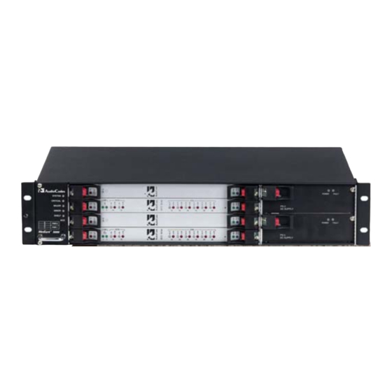
HA system with TP-8410 and TP-6310 are shown respectively in the figures below: Figure 1-2: High Availability System 1+1 of Mediant 3000 with TP-8410 Figure 1-3: High Availability System 1+1 of Mediant 3000 with TP-6310 On the front panel, the active blade occupies Slot 1 while the redundant blade occupies Slot 3. -
Page 22: Initialization Process
Mediant 3000 The RTMs on the rear of the chassis is according to implemented blade: TP-8410: the RTM-8410 is located in Slot 2. The RTM-8410 connects to Trunks 1 through 42 (or 1 through 16). Its PSTN and Gigabit Ethernet (GbE) interfaces are connected to the active VoP blade in Slot 1 of the front panel. -
Page 23: Configuration Stages
IP address that is different than the local IP addresses of the blades, but with the same subnet (refer to Mediant 3000 and IPmedia 3000 Installation Manual). In the HA system, when the VoP blades are initially configured using BootP, the BootP communicates with the two blades using two different local IP addresses: one for the active and one for the redundant blade. -
Page 24: Functional Block Diagrams
Mediant 3000 Functional Block Diagrams The functional block diagrams of the Mediant 3000 with the TP-6310 blade and with the TP- 8410 blade are shown in the figures below, respectively: Figure 1-4: Mediant 3000/TP-6310 Functional Block Diagram SIP User's Manual... -
Page 25: Figure 1-5: Mediant 3000/Tp-8410 Functional Block Diagram
SIP User's Manual 1. Overview Figure 1-5: Mediant 3000/TP-8410 Functional Block Diagram Version 5.8 September 2009... -
Page 26: Sip Overview
Mediant 3000 SIP Overview Session Initiation Protocol (SIP) is an application-layer control (signaling) protocol used on the gateway for creating, modifying, and terminating sessions with one or more participants. These sessions can include Internet telephone calls, media announcements, and conferences. -
Page 27: Configuration Concepts
Note: To initialize the device by assigning it an IP address, a firmware file (cmp), and a configuration file (ini file), you can use AudioCodes' BootP/TFTP utility, which accesses the device using its MAC address (refer to the Product Reference Manual). - Page 28 Mediant 3000 Reader’s Notes SIP User's Manual Document #: LTRT-89707...
-
Page 29: Web-Based Management
SIP User's Manual 3. Web-Based Management Web-Based Management The device's Embedded Web Server (Web interface) provides FCAPS (fault management, configuration, accounting, performance, and security) functionality. The Web interface allows you to remotely configure your device for quick-and-easy deployment, including uploading of software (*.cmp), configuration (*.ini), and auxiliary files, and resetting the device. -
Page 30: Accessing The Web Interface
Mediant 3000 3.1.2 Accessing the Web Interface The Web interface can be opened using any standard Web browser (refer to ''Computer Requirements'' on page 29). When initially accessing the Web interface, use the default user name ('Admin') and password ('Admin'). For changing the login user name and password, refer to ''Configuring the Web User Accounts'' on page 90). -
Page 31: Areas Of The Gui
SIP User's Manual 3. Web-Based Management 3.1.3 Areas of the GUI The figure below displays the general layout of the Graphical User Interface (GUI) of the Web interface: Figure 3-2: Main Areas of the Web Interface GUI The Web GUI is composed of the following main areas: Title bar: Displays the corporate logo and product name. -
Page 32: Toolbar
Software Upgrade Wizard: opens the 'Software Upgrade Wizard' page for upgrading the device's software (refer to ''Software Upgrade Wizard'' on page 197). Switch Over: opens the 'Mediant 3000' page for performing a switch-over between Active and Redundant blades (refer to “High Availability Blade Switch-Over” on page 191). -
Page 33: Navigation Tree
SIP User's Manual 3. Web-Based Management 3.1.5 Navigation Tree The Navigation tree, located in the Navigation pane, displays the menus (pertaining to the menu tab selected on the Navigation bar) used for accessing the configuration pages. The Navigation tree displays a tree-like structure of menus. You can easily drill-down to the required page item level to open its corresponding page in the Work pane. -
Page 34: Displaying Navigation Tree In Basic And Full View
Mediant 3000 To navigate to a page: Navigate to the required page item, by performing the following: • Drilling-down using the plus signs to expand the menus and submenus • Drilling-up using the minus signs to collapse the menus and submenus Select the required page item;... -
Page 35: Showing / Hiding The Navigation Pane
SIP User's Manual 3. Web-Based Management 3.1.5.2 Showing / Hiding the Navigation Pane The Navigation pane can be hidden to provide more space for elements displayed in the Work pane. This is especially useful when the Work pane displays a page with a table that's wider than the Work pane and to view the all the columns, you need to use scroll bars. -
Page 36: Accessing Pages
Mediant 3000 3.1.6.1 Accessing Pages The configuration pages are accessed by clicking the required page item in the Navigation tree. To open a configuration page in the Work pane: On the Navigation bar, click the required tab: • Configuration (refer to ''Configuration Tab'' on page 62) •... -
Page 37: Figure 3-7: Toggling Between Basic And Advanced Page View
SIP User's Manual 3. Web-Based Management 3.1.6.2.1 Displaying Basic and Advanced Parameters Some pages provide you with an Advanced Parameter List / Basic Parameter List toggle button that allows you to show or hide advanced parameters (in addition to displaying the basic parameters). -
Page 38: Figure 3-8: Expanding And Collapsing Parameter Groups
Mediant 3000 3.1.6.2.2 Showing / Hiding Parameter Groups Some pages provide groups of parameters, which can be hidden or shown. To toggle between hiding and showing a group, simply click the group name button that appears above each group. The button appears with a down-pointing or up-pointing arrow, indicating that it can be collapsed or expanded when clicked, respectively. -
Page 39: Modifying And Saving Parameters
SIP User's Manual 3. Web-Based Management 3.1.6.3 Modifying and Saving Parameters When you change parameter values on a page, the Edit symbol appears to the right of these parameters. This is especially useful for indicating the parameters that you have currently modified (before applying the changes). -
Page 40: Entering Phone Numbers In Various Tables
Mediant 3000 If you enter an invalid parameter value (e.g., not in the range of permitted values) and then click Submit, a message box appears notifying you of the invalid value. In addition, the parameter value reverts to its previous value and is highlighted in red, as shown in the... -
Page 41: Figure 3-11: Adding An Index Entry To A Table
SIP User's Manual 3. Web-Based Management To add an entry to a table: In the 'Add' field, enter the desired index entry number, and then click Add; an index entry row appears in the table: Figure 3-11: Adding an Index Entry to a Table Click Apply to save the index entry. -
Page 42: Searching For Configuration Parameters
Mediant 3000 To organize the index entries in ascending, consecutive order: Click Compact; the index entries are organized in ascending, consecutive order, starting from index 0. For example, if you added three index entries 0, 4, and 6, then the index entry 4 is re-assigned index number 1 and the index entry 6 is re-assigned index number 2. -
Page 43: Figure 3-13: Searched Result Screen
SIP User's Manual 3. Web-Based Management Click Search; a list of located parameters based on your search appears in the Navigation pane. Each searched result displays the following: • ini file parameter name • Link (in green) to its location (page) in the Web interface •... -
Page 44: Working With Scenarios
Mediant 3000 3.1.8 Working with Scenarios The Web interface allows you to create your own "menu" with up to 20 pages selected from the menus in the Navigation tree (i.e., pertaining to the Configuration, Management, and Status & Diagnostics tabs). The "menu" is a set of configuration pages grouped into a logical entity referred to as a Scenario. -
Page 45: Figure 3-15: Creating A Scenario
SIP User's Manual 3. Web-Based Management Click the Next button located at the bottom of the page; the Step is added to the Scenario and appears in the Scenario Step list: Figure 3-15: Creating a Scenario Repeat steps 5 through 8 to add additional Steps (i.e., pages). When you have added all the required Steps for your Scenario, click the Save &... -
Page 46: Accessing A Scenario
Mediant 3000 3.1.8.2 Accessing a Scenario Once you have created the Scenario, you can access it at anytime by following the procedure below: To access the Scenario: On the Navigation bar, select the Scenario tab; a message box appears, requesting you to confirm the loading of the Scenario. -
Page 47: Editing A Scenario
SIP User's Manual 3. Web-Based Management To navigate between Scenario Steps, you can perform one of the following: In the Navigation tree, click the required Scenario Step. In an opened Scenario Step (i.e., page appears in the Work pane), use the following navigation buttons: •... -
Page 48: Saving A Scenario To A Pc
Mediant 3000 • Add or Remove Parameters: In the Navigation tree, select the required Step; the corresponding page opens in the Work pane. To add parameters, select the check boxes corresponding to the desired parameters; to remove parameters, clear the check boxes corresponding to the parameters that you want removed. -
Page 49: Figure 3-18: Scenario File Page
SIP User's Manual 3. Web-Based Management To save a Scenario to a PC: On the Navigation bar, click the Scenarios tab; the Scenario appears in the Navigation tree. Click the Get/Send Scenario File button (located at the bottom of the Navigation tree); the 'Scenario File' page appears, as shown below: Figure 3-18: Scenario File Page Click the Get Scenario File button;... -
Page 50: Loading A Scenario To The Device
Mediant 3000 3.1.8.5 Loading a Scenario to the Device Instead of creating a Scenario, you can load a Scenario file (data file) from your PC to the device. To load a Scenario to the device: On the Navigation bar, click the Scenarios tab; the Scenario appears in the Navigation tree. -
Page 51: Exiting Scenario Mode
SIP User's Manual 3. Web-Based Management Click the Delete Scenario File button; a message box appears requesting confirmation for deletion. Figure 3-20: Message Box for Confirming Scenario Deletion Click OK; the Scenario is deleted and the Scenario mode closes. Note: You can also delete a Scenario using the following alternative methods: •... -
Page 52: Customizing The Web Interface
The figure below shows an example of a customized Title bar. The top image displays the Title bar with AudioCodes logo and product name. The bottom image displays a customized Title bar with a different image logo and product name. -
Page 53: Figure 3-23: Image Download Screen
SIP User's Manual 3. Web-Based Management On the left pane, click Image Load to Device; the 'Image Download' page is displayed, as shown in the figure below: Figure 3-23: Image Download Screen Click the Browse button, and then navigate to the folder in which the logo image file is located. -
Page 54: Customizing The Product Name
The corporate logo can be replaced with a text string instead of an image. To replace AudioCodes’ default logo with a text string using the ini file, configure the ini file parameters listed in the table below. (For a description on using the ini file, refer to ''Modifying an ini File'' on page 223.) -
Page 55: Creating A Login Welcome Message
SIP User's Manual 3. Web-Based Management 3.1.9.3 Creating a Login Welcome Message You can create a Welcome message box (alert message) that appears after each successful login to the device's Web interface. The ini file table parameter WelcomeMessage allows you to create the Welcome message. Up to 20 lines of character strings can be defined for the message. -
Page 56: Getting Help
Mediant 3000 3.1.10 Getting Help The Web interface provides you with context-sensitive Online Help. The Online Help provides you with brief descriptions of most of the parameters you'll need to successfully configure the device. The Online Help provides descriptions of parameters pertaining to the currently opened page. -
Page 57: Logging Off The Web Interface
SIP User's Manual 3. Web-Based Management 3.1.11 Logging Off the Web Interface You can log off the Web interface and re-access it with a different user account. For detailed information on the Web User Accounts, refer to User Accounts. To log off the Web interface: On the toolbar, click the Log Off button;... -
Page 58: Using The Home Page
By default, the 'Home' page is displayed when you access the device's Web interface. To access the Home page: On the toolbar, click the Home icon; the 'Home' page is displayed. Figure 3-28: Home Page (Example Mediant 3000 with TP-6310) Notes: • The displayed PSTN interface type depends on the device's hardware configuration. -
Page 59: Table 3-5: Areas Of The Home Page
SIP User's Manual 3. Web-Based Management The table below describes the areas of the 'Home' page. Table 3-5: Areas of the Home Page Item # Description Fan Tray unit displaying operating status icons of fans: (green): normal operation (red): fan failure or fan missing You can also view current alarms in the 'Active Alarms' table (refer to “Viewing the Active Alarms Table”... - Page 60 Mediant 3000 Item # Description (green): Active link (for optical STM1/OC3 interface) or “DS3 Synchronized” (for DS3 interface). (yellow): Standby link (for optical STM1/OC3 interface) or “DS3 RAI” (for DS3 interface). PSTN Alarm icon: (gray): No alarm (for optical STM1/OC3 interface) or “No Near-end Alarm” (for DS3 interface).
-
Page 61: High Availability Status
VoIP blades (TP-6310 or TP-8410) and two SA/M3K Alarms, Status and Synchronization ("SAT") blades, as shown in the figure below: Figure 3-29: Home Page for Mediant 3000 HA Device The status of the HA mode is indicated in the General Information pane's 'High Availability'... -
Page 62: Configuration Tab
Mediant 3000 The General Information pane's 'Active Board Slot Number' field indicates the Slot number in which the Active blade is currently located. Notes: • To perform a switch-over between Active and Redundant blades, or to reset the Redundant blade, refer to ''High Availability Blade Switch-Over'' on page 191. -
Page 63: Configuring The Multiple Interface Table
SIP User's Manual 3. Web-Based Management 3.3.1.1 Configuring the Multiple Interface Table The 'Multiple Interface Table' page allows you to configure up to 16 logical network interfaces, each with its own IP address, unique VLAN ID (if enabled), interface name, and application type permitted on the interface: Control Media... -
Page 64: Figure 3-30: Ip Settings Page
To configure the multiple IP interface table: Open the 'IP Settings' page (Configuration tab > Network Settings menu > IP Settings>. For Mediant 3000 HA, skip to Step 3. Figure 3-30: IP Settings Page Under the 'Multiple Interface Settings' group, click the Multiple Interface Table button;... -
Page 65: Table 3-6: Multiple Interface Table Parameters Description
SIP User's Manual 3. Web-Based Management Table 3-6: Multiple Interface Table Parameters Description Parameter Description Table parameters Index Index of each interface. The range is 0 to 15. Note: Each interface index must be unique. Web: Application Type Types of applications that are allowed on the specific EMS: Application Types interface. - Page 66 Mediant 3000 Parameter Description IP address must be defined, with or without another single IPv6-type IP address interface. The single IPv4 interface must be defined for all applications (i.e., OAMP, Media, and Control). If an IPv6 interface is also configured, it can be defined only for Media, Control, or Media and Control.
- Page 67 SIP User's Manual 3. Web-Based Management Parameter Description 10.50.10.1/24 is invalid). Each interface must have its own address space. Web/EMS: Gateway Defines the IP address of the default gateway used by the [InterfaceTable_Gateway] device. Notes: Only one default gateway can be defined for each address family (IPv4 and IPv6).
- Page 68 (Media, Control, and OAMP). [0] Disable (default). [1] Enable. Notes: This parameter is applicable only to Mediant 3000 with TP-8410. For this parameter to take effect, a device reset is required. When the parameter is enabled, user VLANs are not supported (i.e., VlANMode is set to 1).
-
Page 69: Configuring The Application Settings
SIP User's Manual 3. Web-Based Management 3.3.1.2 Configuring the Application Settings The 'Application Settings' page is used for configuring various application parameters such as Network Time Protocol (NTP), daylight saving time, and Telnet. For a description of these parameters, refer to ''Configuration Parameters Reference'' on page 265. To configure the Application settings: Open the 'Application Settings' page (Configuration tab >... -
Page 70: Configuring The Nfs Settings
Mediant 3000 3.3.1.3 Configuring the NFS Settings Network File System (NFS) enables the device to access a remote server's shared files and directories, and to handle them as if they're located locally. You can configure up to five different NFS file systems. As a file system, the NFS is independent of machine types, operating systems, and network architectures. -
Page 71: Configuring The Ip Routing Table
SIP User's Manual 3. Web-Based Management Table 3-7: NFS Settings Parameters Parameter Description Index The row index of the remote file system. The valid range is 0 to 4. Host Or IP The domain name or IP address of the NFS server. If a domain name is provided, a DNS server must be configured. -
Page 72: Figure 3-34: Ip Routing Table Page
Mediant 3000 To configure static IP routing: Open the 'IP Routing Table' page (Configuration tab > Network Settings menu > IP Routing Table page item). Figure 3-34: IP Routing Table Page In the 'Add a new table entry' group, add a new static routing rule according to the parameters described in the table below. -
Page 73: Configuring The Qos Settings
SIP User's Manual 3. Web-Based Management Parameter Description Metric The maximum number of times a packet can be [RoutingTableHopsCountColumn] forwarded (hops) between the device and destination (typically, up to 20). Note: This parameter must be set to a number greater than 0 for the routing rule to be valid. -
Page 74: Media Settings
Mediant 3000 3.3.2 Media Settings The Media Settings menu allows you to configure the device's channel parameters. This menu contains the following items: Voice Settings (refer to ''Configuring the Voice Settings'' on page 74) Fax/Modem/CID Settings (refer to ''Configuring the Fax/Modem/CID Settings'' on page RTP/RTCP Settings (refer to ''Configuring the RTP/RTCP Settings'' on page 76) IPmedia Settings (refer to “Configuring the IPmedia Settings”... -
Page 75: Configuring The Fax/Modem/Cid Settings
SIP User's Manual 3. Web-Based Management Configure the Voice parameters as required. Click the Submit button to save your changes. To save the changes to flash memory, refer to ''Saving Configuration'' on page 190. 3.3.2.2 Configuring the Fax/Modem/CID Settings The 'Fax/Modem/CID Settings' page is used for configuring fax, modem, and Caller ID (CID) parameters. -
Page 76: Configuring The Rtp/Rtcp Settings
Mediant 3000 3.3.2.3 Configuring the RTP/RTCP Settings The 'RTP/RTCP Settings' page allows you to configure the Real-Time Transport Protocol (RTP) and Real-Time Transport (RTP) Control Protocol (RTCP) parameters. For a detailed description of the parameters appearing on this page, refer to ''Configuration Parameters Reference'' on page 265. -
Page 77: Figure 3-39: Ipmedia Settings Page
SIP User's Manual 3. Web-Based Management For a detailed description of the parameters appearing on this page, refer to ''Configuration Parameters Reference'' on page 265. To configure the IP media parameters: Open the 'IPMedia Settings' page (Configuration tab > Media Settings menu > IPmedia Settings page item). -
Page 78: Configuring The General Media Settings
Mediant 3000 3.3.2.5 Configuring the General Media Settings The 'General Media Settings' page allows you to configure various media parameters. For a detailed description of the parameters appearing on this page, refer to ''Configuration Parameters Reference'' on page 265. To configure general media parameters: Open the 'General Media Settings' page (Configuration tab >... -
Page 79: Configuring The Amr Policy Management Settings
SIP User's Manual 3. Web-Based Management Table 3-9: DSP Templates Parameters Parameter Description DSP Template Number Determines the DSP template to use on the device. Each DSP [DSPVersionTemplateNumber] template supports specific coders, channel capacity, and features. The default is DSP template 0. DSP Resources Percentage Resource percentage used for the specified template. -
Page 80: Figure 3-42: Amr Policy Management Page
Mediant 3000 To configure the AMR Policy Management parameters: Open the 'AMR Policy Management' page (Configuration tab > Media Settings menu > AMR Policy Management page item). Figure 3-42: AMR Policy Management Page Add an index entry to the table using the Add button, and then configure the AMR Policy Management parameters according to the table below. -
Page 81: Configuring Media Security
SIP User's Manual 3. Web-Based Management Threshold Value Frame Loss Ratio Hysteresis Value Frame Loss Ratio 14.5% 2.5% 3.3.2.8 Configuring Media Security The 'Media Security' page allows you to configure media security. For a detailed description of the parameters appearing on this page, refer to ''Configuration Parameters Reference'' on page 265. -
Page 82: Pstn Settings
Mediant 3000 3.3.3 PSTN Settings The PSTN Settings menu allows you to configure various PSTN settings and includes the following page items: Trunk Settings (refer to ''Configuring the Trunk Settings'' on page 82) Transmission Settings (refer to “Configuring the Transmission Settings” on page 85) CAS State Machines (refer to ''Configuring the CAS State Machines'' on page 87) 3.3.3.1... -
Page 83: Figure 3-44: Trunk Settings Page
SIP User's Manual 3. Web-Based Management To configure the trunks: Open the ‘Trunk Settings’ page (Configuration tab > PSTN Settings menu > Trunk Settings page item). Figure 3-44: Trunk Settings Page On the top of the page, a bar with Trunk number icons displays the status of each trunk, according to the following color codes: •... -
Page 84: Figure 3-45: Trunk Scroll Bar
Mediant 3000 Select the trunk that you want to configure, by clicking the desired Trunk number icon. The bar initially displays the first eight trunk number icons (i.e., trunks 1 through 8). To scroll through the trunk number icons (i.e., view the next/last or previous/first group of... - Page 85 SIP User's Manual 3. Web-Based Management To save the changes to flash memory, refer to ''Saving Configuration'' on page 190. To reset the device, refer to ''Resetting the Device'' on page 188. Notes: • If the ‘Protocol Type’ field displays 'NONE' (i.e., no protocol type selected) and no other trunks have been configured, after selecting a PRI protocol type, you must reset the device.
-
Page 86: Configuring The Transmission Settings
Mediant 3000 3.3.3.2 Configuring the Transmission Settings The 'Transmission Settings' page allows you to define the PSTN transmission type (i.e., T3/DS3 or SONET/SDH). For a description of the parameters related to transmission type, refer to ''PSTN Parameters'' on page 353. -
Page 87: Configuring The Cas State Machines
SIP User's Manual 3. Web-Based Management Figure 3-47: Transmission Settings Page (DS3) Click the channel icon (SDH Link for SONET/SDH, or DS3 Number for DS3), and then define the transmission settings as required. Click Submit. Reset the device and save your settings to the flash memory (refer to ''Resetting the Device'' on page 188). -
Page 88: Table 3-12: Cas State Machine Parameters Description
Mediant 3000 In the 'CAS State Machine' page, modify the required parameters according to the table below. Once you have completed the configuration, activate the trunk if required in the 'Trunk Settings' page, by clicking the trunk number in the 'Related Trunks' field, and in the 'Trunk Settings' page, select the required Trunk number icon, and then click Apply Trunk Settings. - Page 89 SIP User's Manual 3. Web-Based Management Parameter Description DTMF Min Detection Time Detects digit minimum on time (according to [CasStateMachineDTMFMinOnDetectionTime] DSP detection information event) in msec units. The digit time length must be longer than this value to receive a detection. Any number may be used, but the value must be less than CasStateMachineDTMFMaxOnDetectionTi...
-
Page 90: Ss7 Configuration
Mediant 3000 3.3.4 SS7 Configuration The SS7 Configuration menu allows you to configure SS7. For a description on configuring SS7, refer to the SIP Product Reference Manual. 3.3.5 Sigtran Configuration The Sigtran Configuration menu allows you to configure Sigtran. For a description on configuring Sigtran, refer to the SIP Product Reference Manual. -
Page 91: Table 3-14: Default Attributes For The Web User Accounts
SIP User's Manual 3. Web-Based Management Numeric Access Level Privileges Representation* No access to security-related and file-loading pages; read-only access to the other pages. User Monitor This read-only access level is typically applied to the secondary Web user account. No Access No access to any page. -
Page 92: Figure 3-49: Web User Accounts Page (For Users With 'Security Administrator' Privileges)
Mediant 3000 To change the Web user accounts attributes: Open the 'Web User Accounts' page (Configuration tab > Security Settings menu > Web User Accounts page item). Figure 3-49: WEB User Accounts Page (for Users with 'Security Administrator' Privileges) Note: If you are logged into the Web interface as the Security Administrator, both Web user accounts are displayed on the 'Web User Accounts' page (as shown above). -
Page 93: Configuring The Web And Telnet Access List
SIP User's Manual 3. Web-Based Management To change the password of an account, perform the following: In the field 'Current Password', enter the current password. In the fields 'New Password' and 'Confirm New Password', enter the new password (maximum of 19 case-sensitive characters). Click Change Password;... -
Page 94: Figure 3-50: Web & Telnet Access List Page - Add New Entry
Mediant 3000 To add authorized IP addresses for Web and Telnet interfaces access: Open the 'Web & Telnet Access List' page (Configuration tab > Security Settings menu > Web & Telnet Access List page item). Figure 3-50: Web & Telnet Access List Page - Add New Entry To add an authorized IP address, in the 'Add a New Authorized IP Address' field, enter the required IP address, and then click Add New Address;... -
Page 95: Configuring The Firewall Settings
SIP User's Manual 3. Web-Based Management 3.3.6.3 Configuring the Firewall Settings The device provides an internal firewall, allowing you (the security administrator) to define network traffic filtering rules. You can add up to 50 ordered firewall rules. For each packet received on the network interface, the table is scanned from the top down until a matching rule is found. -
Page 96: Table 3-15: Internal Firewall Parameters
Mediant 3000 To activate a de-activated rule: In the 'Edit Rule' column, select the de-activated rule that you want to activate. Click the Activate button; the rule is activated. To de-activate an activated rule: In the 'Edit Rule' column, select the activated rule that you want to de-activate.. -
Page 97: Configuring The Certificates
SIP User's Manual 3. Web-Based Management Parameter Description Action Upon Match Action upon match (i.e., 'Allow' or 'Block'). [AccessList_Allow_Type] Match Count A read-only field providing the number of packets accepted / rejected [AccessList_MatchCount] by the specific rule. 3.3.6.4 Configuring the Certificates The 'Certificates' page is used for the following: Replacing the server certificate (refer to ''Server Certificate Replacement'' on page 97) Replacing the client certificates (refer to ''Client Certificates'' on page 99) -
Page 98: Figure 3-53: Certificates Signing Request
Mediant 3000 Open the ‘Certificates Signing Request' page (Configuration tab > Security Settings menu > Certificates page item). Figure 3-53: Certificates Signing Request Page In the 'Subject Name' field, enter the DNS name, and then click Generate CSR. A textual certificate signing request that contains the SSL device identifier is displayed. -
Page 99: Figure 3-54: Ike Table Listing Loaded Certificate Files
SIP User's Manual 3. Web-Based Management When the loading of the certificate is complete, save the configuration (refer to ''Saving Configuration'' on page 190) and restart the device; the Web interface uses the provided certificate. If the device was originally operating in HTTPS mode and you disabled it in Step 2, then return it to HTTPS by setting the parameter 'Secured Web Connection (HTTPS)' to 'HTTPS Only' (1) (refer to ''Configuring the General Security Settings'' on page 101). - Page 100 Mediant 3000 3.3.6.4.2 Client Certificates By default, Web servers using SSL provide one-way authentication. The client is certain that the information provided by the Web server is authentic. When an organizational PKI is used, two-way authentication may be desired: both client and server should be authenticated using X.509 certificates.
- Page 101 SIP User's Manual 3. Web-Based Management 3.3.6.4.3 Self-Signed Certificates The device is shipped with an operational, self-signed server certificate. The subject name for this default certificate is 'ACL_nnnnnnn', where nnnnnnn denotes the serial number of the device. However, this subject name may not be appropriate for production and can be changed while still using self-signed certificates.
-
Page 102: Configuring The General Security Settings
Mediant 3000 3.3.6.5 Configuring the General Security Settings The 'General Security Settings' page is used to configure various security features. For a description of the parameters appearing on this page, refer ''Configuration Parameters Reference'' on page 265. To configure the general security parameters: Open the 'General Security Settings' page (Configuration tab >... -
Page 103: Configuring The Ipsec Table
SIP User's Manual 3. Web-Based Management 3.3.6.6 Configuring the IPSec Table The 'IPSec Table' page allows you to configure the Security Policy Database (SPD) parameters for IP security (IPSec). Note: You can also configure the IPSec table using the ini file table parameter IPSEC_SPD_TABLE (refer to ''Security Parameters'' on page 289). -
Page 104: Table 3-16: Default Ike Second Phase Proposals
Mediant 3000 If no IPSec methods are defined (Encryption / Authentication), the default settings, shown in the following table are applied. Table 3-16: Default IKE Second Phase Proposals Proposal Encryption Authentication Proposal 0 3DES SHA1 Proposal 1 3DES Proposal 2... - Page 105 SIP User's Manual 3. Web-Based Management Parameter Name Description Protocol Defines the protocol type to which the [IPSecPolicyProtocol] IPSec mechanism is applied. 0 = Any protocol (default). 17 = UDP. 6 = TCP. Any other protocol type defined by IANA (Internet Assigned Numbers Authority).
-
Page 106: Configuring The Ike Table
Mediant 3000 3.3.6.7 Configuring the IKE Table The 'IKE Table' page is used to configure the Internet Key Exchange (IKE) parameters. Note: You can also configure the IKE table using the ini file table parameter IPSec_IKEDB_Table (refer to ''Security Parameters'' on page 289). -
Page 107: Table 3-18: Default Ike First Phase Proposals
SIP User's Manual 3. Web-Based Management If no IKE methods are defined (Encryption / Authentication / DH Group), the default settings (shown in the following table) are applied. Table 3-18: Default IKE First Phase Proposals Proposal Encryption Authentication DH Group Proposal 0 3DES SHA1... - Page 108 Mediant 3000 Parameter Name Description IKE SA LifeTime (sec) Determines the time (in seconds) the SA negotiated in the [IKEPolicyLifeInSec] first IKE session (main mode) is valid. After the time expires, the SA is re-negotiated. The default value is 28800 (i.e., 8 hours).
-
Page 109: Protocol Configuration
SIP User's Manual 3. Web-Based Management 3.3.7 Protocol Configuration The Protocol Configuration menu allows you to configure the device's SIP parameters and contains the following submenus: Applications Enabling (refer to “Enabling Applications” on page 109) Media Realms (refer to “Configuring Media Realms” on page 110) Protocol Definition (refer to ''Protocol Definition'' on page 111) Proxies/IpGroups/Registration (refer to ''Proxies, IP Groups, and Registration'' on page 114) -
Page 110: Configuring Media Realms
Mediant 3000 3.3.7.2 Configuring Media Realms The 'SIP Media Realm Table' page allows you to define a pool of up to 16 media interfaces, termed Media Realms. This table allows you to divide a Media-type interface (defined in the 'Multiple Interface' table - refer to ''Configuring the Multiple Interface Table'' on page 62) into several realms, where each realm is specified by a UDP port range. - Page 111 SIP User's Manual 3. Web-Based Management Parameter Description IPv4 Name Associates the IPv4 interface to the Media Realm. The name [CpMediaRealm_IPv4IF] of this IPv4 interface must be exactly as configured in the 'Multiple Interface' table (InterfaceTable). IPv6 Name Associates the IPv6 interface with the media realm. This [CpMediaRealm_IPv6IF] name must be exactly as configured in the 'Multiple Interface' table.
-
Page 112: Protocol Definition
Mediant 3000 3.3.7.3 Protocol Definition The Protocol Definition submenu allows you to configure the main SIP protocol parameters. This submenu contains the following page items: SIP General Parameters (refer to ''SIP General Parameters'' on page 112) DTMF & Dialing (refer to ''DTMF & Dialing Parameters'' on page 114) 3.3.7.3.1 Configuring SIP General Parameters... -
Page 113: Figure 3-60: Sip General Parameters
SIP User's Manual 3. Web-Based Management Figure 3-60: SIP General Parameters Page Configure the parameters as required. Click the Submit button to save your changes. To save the changes to flash memory, refer to ''Saving Configuration'' on page 190. Version 5.8 September 2009... -
Page 114: Proxies, Ip Groups, And Registration
Mediant 3000 3.3.7.3.2 Configuring DTMF and Dialing Parameters The 'DTMF & Dialing' page is used to configure parameters associated with dual-tone multi- frequency (DTMF) and dialing. For a description of the parameters appearing on this page, refer to ''Configuration Parameters Reference'' on page 265. -
Page 115: Figure 3-62: Proxy & Registration
SIP User's Manual 3. Web-Based Management To configure the Proxy & Registration parameters: Open the 'Proxy & Registration' page (Configuration tab > Protocol Configuration menu > Proxies/IpGroups/Registration submenu > Proxy & Registration page item). Figure 3-62: Proxy & Registration Page Configure the parameters as required. -
Page 116: Figure 3-63: Proxy Sets Table
Mediant 3000 3.3.7.4.2 Configuring the Proxy Sets Table The 'Proxy Sets Table' page allows you to define Proxy Sets. A Proxy Set is a group of Proxy servers defined by IP address or fully qualified domain name (FQDN). You can define up to six Proxy Sets, each having a unique ID number and each containing up to five Proxy server addresses. -
Page 117: Table 3-21: Proxy Sets Table Parameters
SIP User's Manual 3. Web-Based Management From the Proxy Set ID drop-down list, select an ID for the desired group. Configure the Proxy parameters according to the following table. Click the Submit button to save your changes. To save the changes to flash memory, refer to ''Saving Configuration'' on page 190. Table 3-21: Proxy Sets Table Parameters Parameter Description... - Page 118 Mediant 3000 Parameter Description messages (if RegistrarIP is not defined). Notes: If EnableProxyKeepAlive is set to 1 or 2, the device monitors the connection with the Proxies by using keep-alive messages (OPTIONS or REGISTER). To use Proxy Redundancy, you must specify one or more redundant Proxies.
- Page 119 SIP User's Manual 3. Web-Based Management Parameter Description The SRV response includes several records with a different Priority value. Web/EMS: Enable Proxy Keep Determines whether Keep-Alive with the Proxy is enabled or Alive disabled. This parameter is configured per Proxy Set. [EnableProxyKeepAlive] [0] Disable = Disable (default).
-
Page 120: Figure 3-64: Ip Group Table
Mediant 3000 3.3.7.4.3 Configuring the IP Groups The 'IP Group Table' page allows you to create up to nine logical IP entities called IP Groups. These IP Groups are used for call routing. The IP Group can be used as a... -
Page 121: Table 3-22: Ip Group Parameters
SIP User's Manual 3. Web-Based Management Configure the IP group parameters according to the table below. Click the Submit button to save your changes. To save the changes to flash memory, refer to ''Saving Configuration'' on page 190. Table 3-22: IP Group Parameters Parameter Description Common Parameters... - Page 122 Mediant 3000 Parameter Description SIP Group Name The request URI host name used in INVITE and REGISTER [IPGroup_SIPGroupName] messages that are sent to this IP Group, or the host name in the From header of INVITE messages received from this IP Group.
- Page 123 SIP User's Manual 3. Web-Based Management Parameter Description the selected Serving IP Group. If no Serving IP Group is selected, the default IP Group is used. If the Proxy server(s) associated with the destination IP Group is not alive, the device uses the 'Outbound IP Routing' table (if the parameter IsFallbackUsed is set 1, i.e., fallback enabled - refer to “Configuring Proxy and Registration Parameters”...
- Page 124 Mediant 3000 Parameter Description Survivability mode, the device is capable of receiving new registrations. When the Serving IP Group is available again, the device returns to normal mode, sending INVITE and REGISTER messages to the Serving IP Group. Notes: This field is available only if the IP-to-IP application is enabled.
-
Page 125: Table 3-23: Account Table Parameters Description
SIP User's Manual 3. Web-Based Management To configure Accounts: Open the 'Account Table' page (Configuration tab > Protocol Configuration menu > Proxies/IpGroups/Registration submenu > Account Table page item). Figure 3-65: Account Table Page To add an Account, in the 'Add' field, enter the desired table row index, and then click Add. - Page 126 Mediant 3000 Parameter Description Serving IP Group The destination IP Group ID (defined in ''Configuring the IP [Account_ServingIPGroup] Groups'' on page 120) to where the REGISTER requests (if enabled) are sent or Authentication is performed. The actual destination to where the REGISTER requests are sent is the IP address defined for the Proxy Set ID (refer to ''Configuring the Proxy Sets Table'' on page 116) associated with this IP Group.
- Page 127 'Trunk Group Settings' table for the specific Trunk Group. The Host Name (i.e., host name in SIP From/To headers) and Contact User (user in From/To and Contact headers) are taken from this table upon a successful registration. See the example below: REGISTER sip:audiocodes SIP/2.0 Via: SIP/2.0/UDP 10.33.37.78;branch=z9hG4bKac1397582418 From: <sip:ContactUser@HostName>;tag=1c1397576231...
-
Page 128: Coders And Profile Definitions
Mediant 3000 3.3.7.5 Coders and Profile Definitions The Coders And Profile Definitions submenu includes the following page items: Coders (refer to ''Configuring Coders'' on page 128) Coder Group Settings (refer to ''Configuring Coder Groups'' on page 130) Tel Profile Settings (refer to ''Configuring Tel Profiles'' on page 131) -
Page 129: Figure 3-66: Coders
SIP User's Manual 3. Web-Based Management 3.3.7.5.1 Configuring Coders The 'Coders' page allows you to configure up to five coders (and their attributes) for the device. The first coder in the list has the highest priority and is used by the device whenever possible. -
Page 130: Configuring Coder Groups
Mediant 3000 From the 'Silence Suppression' drop-down list, enable or disable the silence suppression option for the selected coder. Repeat steps 2 through 6 for the second to fifth optional coders. Click the Submit button to save your changes. To save the changes to flash memory, refer to ''Saving Configuration'' on page 190. -
Page 131: Figure 3-67: Coder Group Settings
SIP User's Manual 3. Web-Based Management To configure coder groups: Open the 'Coder Group Settings' page (Configuration tab > Protocol Configuration menu > Coders And Profile Definition submenu > Coder Group Settings page item). Figure 3-67: Coder Group Settings Page From the 'Coder Group ID' drop-down list, select a coder group ID. -
Page 132: Figure 3-68: Tel Profile Settings
Mediant 3000 3.3.7.5.3 Configuring Tel Profile The 'Tel Profile Settings' page allows you to define up to nine Tel Profiles. You can then assign these Tel Profiles to the device's channels (in the 'Trunk Group Table' page), thereby applying different behaviors to different channels. -
Page 133: Configuring Ip Profiles
SIP User's Manual 3. Web-Based Management From the 'Profile Preference' drop-down list, select the priority of the Tel Profile, where '1' is the lowest priority and '20' is the highest. If both IP and Tel profiles apply to the same call, the coders and other common parameters (noted by an asterisk in the description of the parameter TelProfile) of the preferred Profile are applied to that call. -
Page 134: Figure 3-69: Ip Profile Settings
Mediant 3000 To configure the IP Profile settings: Open the 'IP Profile Settings' page (Configuration tab > Protocol Configuration menu > Coders And Profile Definition submenu > IP Profile Settings). Figure 3-69: IP Profile Settings Page From the 'Profile ID' drop-down list, select an identification number for the IP Profile. -
Page 135: Table 3-24: Description Of Parameter Unique To Ip Profile
SIP User's Manual 3. Web-Based Management From the 'Profile Preference' drop-down list, select the priority of the IP Profile, where '1' is the lowest priority and '20' is the highest. If both IP and Tel profiles apply to the same call, the coders and other common parameters (noted by an asterisk) of the preferred Profile are applied to that call. -
Page 136: Sip Advanced Parameters
Mediant 3000 3.3.7.6 SIP Advanced Parameters The SIP Advanced Parameters submenu allows you to configure advanced SIP control protocol parameters. This submenu contains the following page items: Advanced Parameters (refer to ''Configuring Advanced Parameters'' on page 136) Supplementary Services (refer to ''Configuring Supplementary Services'' on page 137) 3.3.7.6.1 Configuring Advanced Parameters... -
Page 137: Figure 3-71: Supplementary Services
SIP User's Manual 3. Web-Based Management Configure the parameters as required. Click the Submit button to save your changes. To save the changes to flash memory, refer to ''Saving Configuration'' on page 190. 3.3.7.6.2 Configuring Supplementary Services The 'Supplementary Services' page is used to configure parameters that are associated with supplementary services. -
Page 138: Sas Parameters
Mediant 3000 3.3.7.7 SAS Parameters The SAS submenu allows you to configure the SAS application. This submenu includes the Stand Alone Survivability item page (refer to ''Configuring Stand-Alone Survivability Parameters'' on page 138), from which you can also access the 'IP2IP Routing Table' page for configuring SAS routing rules (refer to ''Configuring the IP2IP Routing Table (SAS)'' on page 139). -
Page 139: Figure 3-72: Sas Configuration
SIP User's Manual 3. Web-Based Management To configure the Stand-Alone Survivability parameters: Open the 'SAS Configuration' page (Configuration tab > Protocol Configuration menu > SAS submenu > Stand Alone Survivability page item). Figure 3-72: SAS Configuration Page Configure the parameters as described in ''SIP Configuration Parameters'' on page 301. -
Page 140: Table 3-25: Sas Routing Table Parameters
Mediant 3000 3.3.7.7.2 Configuring the IP2IP Routing Table (SAS) The 'IP2IP Routing Table' page configures SAS routing when SAS is in Emergency mode. Up to 120 SAS routing rules can be defined. The device routes the SAS call (received SIP INVITE message) once a rule in this table is matched. - Page 141 SIP User's Manual 3. Web-Based Management Parameter Description Destination Username Prefix The prefix of the incoming SIP INVITE's destination URI [IP2IPRouting_DestUsernamePrefix] (usually the Request URI) user part. If this rule is not required, leave the field empty. To denote any prefix, use the asterisk (*) symbol.
-
Page 142: Manipulation Tables
Mediant 3000 Parameter Description Destination Address The destination IP address (or domain name, e.g., [IP2IPRouting_DestAddress] domain.com) to where the call is sent. Notes: This parameter is applicable only if the parameter 'Destination Type' is set to 'Dest Address' [1]. When using domain names, enter a DNS server IP... - Page 143 SIP User's Manual 3. Web-Based Management Assigning Numbering Plan Indicator (NPI)/Type of Numbering (TON) to IP-to-Tel calls. The device can use a single global setting for NPI/TON classification or it can use the setting in the manipulation tables on a call-by-call basis. The number manipulation is configured in the following tables: For Tel-to-IP calls: •...
-
Page 144: Table 3-26: Number Manipulation Parameters Description
Mediant 3000 The device matches manipulation rules starting at the top of the table. In other words, a rule at the top of the table takes precedence over a rule defined lower down in the table. Therefore, define more specific rules above more generic rules. For example, if you enter 551 in Index 1 and 55 in Index 2, the device applies rule 1 to numbers that start with 551 and applies rule 2 to numbers that start with 550, 552, 553, and so on untill 559. - Page 145 SIP User's Manual 3. Web-Based Management Parameter Description For IP-to-IP call routing, this parameter is not required (i.e., leave the field empty). Source IP Group The IP Group from where the IP-to-IP call originated. Typically, this IP [_SrcIPGroupID] Group of an incoming INVITE is determined/classified using the ‘Inbound IP Routing’...
- Page 146 Mediant 3000 Parameter Description Web/EMS: Number of Digits The number of digits that you want to retain from the right of the to Leave phone number. [_LeaveFromRight] Web: NPI The Numbering Plan Indicator (NPI) assigned to this entry. EMS: Number Plan...
-
Page 147: Figure 3-75: Phone Context Table
SIP User's Manual 3. Web-Based Management 3.3.7.8.2 Mapping NPI/TON to SIP Phone-Context The 'Phone-Context Table' page is used to map Numbering Plan Indication (NPI) and Type of Number (TON) to the SIP Phone-Context parameter. When a call is received from the ISDN, the NPI and TON are compared against the table and the matching Phone-Context value is used in the outgoing SIP INVITE message. -
Page 148: Table 3-27: Phone-Context Parameters Description
Mediant 3000 Table 3-27: Phone-Context Parameters Description Parameter Description Add Phone Context As Prefix Determines whether the received Phone-Context parameter is [AddPhoneContextAsPrefix] added as a prefix to the outgoing ISDN SETUP message with Called and Calling numbers. [0] Disable = Disable (default). - Page 149 SIP User's Manual 3. Web-Based Management Description National [2] A public number in complete national E.164 format, e.g., 6135551234. Subscriber [4] A public number in complete E.164 format representing a local subscriber, e.g., 5551234. Private [9] Unknown [0] A private number, but with no further information about the numbering plan.
-
Page 150: Routing Tables
Mediant 3000 3.3.7.9 Routing Tables The Routing Tables submenu allows you to configure call routing rules. This submenu includes the following page items: Routing General Parameters (refer to ''Configuring Routing General Parameters'' on page 150) Tel to IP Routing (refer to ''Configuring the Tel to IP Routing Table'' on page 151) Outbound IP Routing (refer to “Configuring the Outbound IP Routing Table”... - Page 151 SIP User's Manual 3. Web-Based Management Configure the parameters as required. Click the Submit button to save your changes. To save the changes to flash memory, refer to ''Saving Configuration'' on page 190. 3.3.7.9.2 Configuring the Tel to IP Routing Table The 'Tel to IP Routing' page provides a table for configuring up to 180 Tel-to-IP call routing rules.
-
Page 152: Figure 3-77: Tel To Ip Routing
Mediant 3000 Assign Profiles to destination addresses (also when a Proxy is used). Alternative Routing (when a Proxy isn't used): an alternative IP destination for telephone number prefixes is available. To associate an alternative IP address to a called telephone number prefix, assign it with an additional entry (with a different IP address), or use an FQDN that resolves into two IP addresses. -
Page 153: Table 3-29: Tel To Ip Routing Table Parameters
SIP User's Manual 3. Web-Based Management From the 'Routing Index' drop-down list, select the range of entries that you want to add. Configure the Tel to IP Routing table according to the table below. Click the Submit button to save your changes. To save the changes to flash memory, refer to ''Saving Configuration'' on page 190. - Page 154 Mediant 3000 Parameter Description Web: Dest. Phone Prefix Called telephone number prefix. EMS: Destination Phone The prefix can include up to 50 digits. Prefix Note: The destination phone prefix can be a single digit or a range of [PREFIX_DestinationPrefix] digits. For available notations representing multiple numbers/digits, refer to ''Dialing Plan Notation for Routing and Manipulation'' on page 447.
- Page 155 SIP User's Manual 3. Web-Based Management Parameter Description Web: Port The destination port to where you want to route the call. EMS: Destination Port [PREFIX_DestPort] Web/EMS: Transport Type The transport layer type for sending the IP calls: [PREFIX_TransportType] [-1] Not Configured [0] UDP [1] TCP [2] TLS...
-
Page 156: Figure 3-78: Outbound Ip Routing
Mediant 3000 3.3.7.9.3 Configuring the Outbound IP Routing Table The 'Outbound IP Routing Table' page allows you to configure the device for routing outbound (i.e., sent) IP-to-IP calls. This table routes inbound IP calls (identified in ''Configuring the Inbound IP Routing Table'' on page 161) received from an IP Group (refer to ''Configuring the IP Groups'' on page 120) to a specific IP Group destination (or IP address). -
Page 157: Table 3-30: Outbound Ip Routing Table Description
SIP User's Manual 3. Web-Based Management Table 3-30: Outbound IP Routing Table Description Parameter Description Tel to IP Routing Mode Determines whether to route the inbound IP calls to the IP [RouteModeTel2IP] destination before or after manipulation of destination number. [0] Route calls before manipulation = IP-to-IP calls are routed before the number manipulation rules are applied (default). - Page 158 Mediant 3000 Parameter Description Dest. IP Address The destination IP address to where the outbound call is sent. [PREFIX_DestAddress] Domain names (e.g., domain.com) can be used instead of IP addresses. Notes: If you select a destination IP Group (in the 'Dest IP Group ID' field below), then the IP address you define in this 'Dest IP Address' field is not used for routing and therefore, not required.
- Page 159 SIP User's Manual 3. Web-Based Management Parameter Description Status A read-only field representing the Quality of Service of the destination IP address: n/a = Alternative Routing feature is disabled. OK = IP route is available. Ping Error = No ping to IP destination; route is not available. QoS Low = Bad QoS of IP destination;...
-
Page 160: Table 3-31: Ip To Trunk Group Routing Table Description
Mediant 3000 To configure the IP to Trunk Group Routing table: Open the 'IP to Trunk Group Routing' page (Configuration tab > Protocol Configuration menu > Routing Tables submenu > IP to Trunk Group Routing page item). Figure 3-79: IP to Trunk Group Routing Table Page From the 'Routing Index' drop-down list, select the entry range of that you want to add. - Page 161 SIP User's Manual 3. Web-Based Management Parameter Description Dest. Phone Prefix Represents a called telephone number prefix. [PstnPrefix_DestPrefix] The prefix can be 1 to 49 digits long. Note: For notations representing multiple numbers, refer to ''Dialing Plan Notation for Routing and Manipulation'' on page 447. Source Phone Prefix Represents a calling telephone number prefix.
-
Page 162: Figure 3-80: Inbound Ip Routing Table
Mediant 3000 3.3.7.9.5 Configuring the Inbound IP Routing Table The 'Inbound IP Routing Table' page allows you to identify received calls as inbound IP-to- IP calls and assign them to an IP Group (defined in ''Configuring the IP Groups'' on page 120), termed the Source IP Group. -
Page 163: Table 3-32: Inbound Ip Routing Table Description
SIP User's Manual 3. Web-Based Management Table 3-32: Inbound IP Routing Table Description Parameter Description IP to Tel Routing Mode Determines whether to route the IP calls before or after manipulation [RouteModeIP2Tel] of the destination number (configured in ''Configuring the Number Manipulation Tables'' on page 142). -
Page 164: Figure 3-81: Internal Dns Table
Mediant 3000 3.3.7.9.6 Configuring the Internal DNS Table The 'Internal DNS Table' page, similar to a DNS resolution is used to translate up to 20 host (domain) names into IP addresses (e.g., when using the 'Tel to IP Routing' table). Up to four different IP addresses can be assigned to the same host name, typically used for alternative routing (for Tel-to-IP call routing). -
Page 165: Figure 3-82: Internal Srv Table
SIP User's Manual 3. Web-Based Management 3.3.7.9.7 Configuring the Internal SRV Table The 'Internal SRV Table' page provides a table for resolving host names to DNS A- Records. Three different A-Records can be assigned to each host name. Each A-Record contains the host name, priority, weight, and port. -
Page 166: Figure 3-83: Release Cause Mapping
Mediant 3000 3.3.7.9.8 Configuring Release Cause Mapping The 'Release Cause Mapping' page consists of two groups that allow the device to map up to 12 different SIP Response Codes to Q.850 Release Causes and vice versa, thereby overriding the hard-coded mapping mechanism (described in ''Release Reason Mapping'' on page 528). -
Page 167: Figure 3-84: Reasons For Alternative Routing
SIP User's Manual 3. Web-Based Management 3.3.7.9.9 Configuring Reasons for Alternative Routing The 'Reasons for Alternative Routing' page allows you to define up to four different call release (termination) reasons for IP-to-Tel call releases and for Tel-to-IP call releases. If a call is released as a result of one of these reasons, the device tries to find an alternative route for that call. -
Page 168: Trunk Groups
Mediant 3000 In the 'IP to Tel Reasons' group, select up to four different call failure reasons that invoke an alternative IP-to-Tel routing. In the 'Tel to IP Reasons' group, select up to four different call failure reasons that invoke an alternative Tel-to-IP routing. -
Page 169: Table 3-33: Trunk Group Table Parameters
SIP User's Manual 3. Web-Based Management Table 3-33: Trunk Group Table Parameters Parameter Description From Trunk Starting physical Trunk number in the Trunk Group. The [TrunkGroup_FirstTrunkId] number of listed Trunks depends on the device's hardware configuration. To Trunk Ending physical Trunk number in the Trunk Group. The [TrunkGroup_LastTrunkId] number of listed Trunks depends on the device's hardware configuration. - Page 170 Mediant 3000 Parameter Description Trunk Group ID The Trunk Group ID (1-99) assigned to the corresponding [TrunkGroup_TrunkGroupNum] channels. The same Trunk Group ID can be assigned to more than one group of channels. The Trunk Group ID is used to define a group of common channel behavior that are used for routing IP-to-Tel calls.
-
Page 171: Figure 3-86: Trunk Group Settings
Per Endpoint mode. The "SipGroupName" in the request URI is taken from the IP Group table. REGISTER sip:SipGroupName SIP/2.0 Via: SIP/2.0/UDP 10.33.37.78;branch=z9hG4bKac862428454 From: <sip:101@GatewayName>;tag=1c862422082 To: <sip:101@GatewayName> Call-ID: 9907977062512000232825@10.33.37.78 CSeq: 3 REGISTER Contact: <sip:101@10.33.37.78>;expires=3600 Expires: 3600 User-Agent: Audiocodes-Sip-Gateway/v.5.80A.008.002 Content-Length: 0 Version 5.8 September 2009... -
Page 172: Table 3-34: Trunk Group Settings Parameters
Mediant 3000 Table 3-34: Trunk Group Settings Parameters Parameter Description Trunk Group ID The Trunk Group ID that you want to configure. [TrunkGroupSettings_TrunkGroupI The valid range is 1 to 99. Channel Select Mode The method for which IP-to-Tel calls are assigned to [TrunkGroupSettings_ChannelSele channels pertaining to a Trunk Group. - Page 173 SIP User's Manual 3. Web-Based Management Parameter Description Registration Parameters'' on page 114). If the device is configured globally (ChannelSelectMode) to register Per Endpoint, and a Trunk Group comprising four channels is configured to register Per Gateway, the device registers all channels except the first four channels.
-
Page 174: Configuring Digital Gateway Parameters
Mediant 3000 3.3.7.11 Configuring Digital Gateway Parameters The 'Digital Gateway Parameters' page allows you to configure miscellaneous digital parameters. For a description of these parameters, refer to ''Configuration Parameters Reference'' on page 265. To configure the digital gateway parameters: Open the 'Digital Gateway Parameters' page (Configuration tab > Protocol Configuration menu >... -
Page 175: Advanced Applications
SIP User's Manual 3. Web-Based Management Configure the parameters as required. Click the Submit button to save your changes. To save the changes to flash memory, refer to ''Saving Configuration'' on page 190. 3.3.8 Advanced Applications The Advanced Applications menu allows you to configure advanced SIP-based applications. -
Page 176: Configuring Voice Mail Parameters
Mediant 3000 3.3.8.1 Configuring Voice Mail Parameters The 'Voice Mail Settings' page allows you to configure the voice mail parameters. For a description of these parameters, refer to ''Configuration Parameters Reference'' on page 265. Notes: • The 'Voice Mail Settings' page is available only for CAS interfaces. -
Page 177: Configuring Radius Accounting Parameters
SIP User's Manual 3. Web-Based Management 3.3.8.2 Configuring RADIUS Accounting Parameters The 'RADIUS Parameters' page is used for configuring the Remote Authentication Dial In User Service (RADIUS) accounting parameters. For a description of these parameters, refer to ''Configuration Parameters Reference'' on page 265. To configure the RADIUS parameters: Open the ‘RADIUS Parameters' page (Configuration tab >... -
Page 178: Tdm And Timing Configuration
Mediant 3000 3.3.9 TDM and Timing Configuration The TDM & Timing Configuration menu allows you to configure TDM and clock timing parameters. This menu includes the following items: TDM (refer to ''Configuring TDM Bus Settings'' on page 178) Digital PCM Settings (refer to ''Configuring Digital PCM Settings'' on page 178) -
Page 179: Configuring Digital Pcm Settings
SIP User's Manual 3. Web-Based Management 3.3.9.2 Configuring Digital PCM Settings The 'Digital PCM Settings' page allows you to configure the PCM companding law in input/output TDM bus, and PCM and ABCD patterns. For a description of these parameters, refer to ''PSTN Parameters'' on page 353. To configure the digital PCM settings: Open the 'Digital PCM Settings' page (Configuration tab >... -
Page 180: Configuring System Timing
Mediant 3000 3.3.9.3 Configuring System Timing The 'System Timing' page allows you to configure the device's clock synchronization mechanism. For a description of these parameters, refer to ''PSTN Parameters'' on page 353. To configure the device's system timing: Open the 'System Timing' page (Configuration tab > TDM & Timing Configuration menu >... -
Page 181: Management Tab
SIP User's Manual 3. Web-Based Management Management Tab The Management tab on the Navigation bar displays menus in the Navigation tree related to device management. These menus include the following: Management Configuration (refer to ''Management Configuration'' on page 181) Software Update (refer to ''Software Update'' on page 192) 3.4.1 Management Configuration The Management Configuration menu allows you to configure the device's management... -
Page 182: Configuring The Management Settings
Mediant 3000 3.4.1.1 Configuring the Management Settings The 'Management Settings' page allows you to configure the device's management parameters. For detailed description on the SNMP parameters, refer to ''SNMP Parameters'' on page 299. To configure the Management parameters: Open the 'Management Settings' page (Management tab > Management Configuration menu >... -
Page 183: Table 3-35: Snmp Trap Destinations Parameters Description
SIP User's Manual 3. Web-Based Management • SNMP Trusted Managers: Click the arrow button to configure the SNMP Trusted Managers (refer to ''Configuring SNMP Trusted Managers'' on page 187). Click the Submit button to save your changes. To save the changes to flash memory, refer to ''Saving Configuration'' on page 190. 3.4.1.1.1 Configuring the SNMP Trap Destinations Table The 'SNMP Trap Destinations' page allows you to configure up to five SNMP trap managers. -
Page 184: Figure 3-95: Snmp Community Strings
Mediant 3000 Parameter Description IP Address IP address of the remote host used as an SNMP [SNMPManagerTableIP_x] Manager. The device sends SNMP traps to these IP addresses. Enter the IP address in dotted-decimal notation, e.g., 108.10.1.255. Trap Port Defines the port number of the remote SNMP Manager. -
Page 185: Table 3-36: Snmp Community Strings Parameters Description
SIP User's Manual 3. Web-Based Management Click the Submit button to save your changes. To save the changes to flash memory, refer to ''Saving Configuration'' on page 190. Note: To delete a community string, select the Delete check box corresponding to the community string that you want to delete, and then click Submit. -
Page 186: Table 3-37: Snmp V3 Users Parameters
Mediant 3000 Click the Apply button to save your changes. To save the changes, refer to ''Saving Configuration'' on page 190. Notes: • For a description of the web interface's table command buttons (e.g., Duplicate and Delete), refer to ''Working with Tables'' on page 40. -
Page 187: Configuring The Regional Settings
SIP User's Manual 3. Web-Based Management 3.4.1.1.4 Configuring SNMP Trusted Managers The 'SNMP Trusted Managers' page allows you to configure up to five SNMP Trusted Managers, based on IP addresses. By default, the SNMP agent accepts SNMP Get and Set requests from any IP address, as long as the correct community string is used in the request. -
Page 188: Maintenance Actions
Mediant 3000 Click the Submit button; the date and time are automatically updated. Notes: • If the device is configured to obtain the date and time from an SNTP server (refer to ''Configuring the Application Settings'' on page 68), the fields on this page are read-only and cannot be modified. -
Page 189: Figure 3-100: Reset Confirmation Message Box
SIP User's Manual 3. Web-Based Management To reset the device: Open the 'Maintenance Actions' page (refer to ''Maintenance Actions'' on page 188). Under the 'Reset Configuration' group, from the 'Burn To FLASH' drop-down list, select one of the following options: •... -
Page 190: Figure 3-101: Device Lock Confirmation Message Box
Mediant 3000 3.4.1.3.2 Locking and Unlocking the Device The Lock and Unlock options allow you to lock the device so that it doesn't accept any new incoming calls. This is useful when, for example, you are uploading new software files to the device and you don't want any traffic to interfere with the process. -
Page 191: High Availability Blade Switch-Over
SIP User's Manual 3. Web-Based Management To save the changes to the non-volatile flash memory : Open the 'Maintenance Actions' page (refer to ''Maintenance Actions'' on page 188). Under the 'Save Configuration' group, click the BURN button; a confirmation message appears when the configuration successfully saves. -
Page 192: Software Update
Mediant 3000 3.4.2 Software Update The Software Update menu allows you to upgrade the device's software by loading a new cmp file (compressed firmware) along with the ini file and a suite of auxiliary files. This menu includes the following page items: Load Auxiliary Files (refer to ''Loading Auxiliary Files'' on page 192) Software Upgrade Key (refer to “Loading a Software Upgrade Key”... -
Page 193: Figure 3-103: Load Auxiliary Files
SIP User's Manual 3. Web-Based Management 3.4.2.1.1 Loading Auxiliary Files using Web Interface The auxiliary files can be loaded to the device using the Web interface's 'Load Auxiliary Files' page, as described in the procedure below. Notes: • When loading an ini file, the settings of parameters that are excluded from the loaded ini file are retained (incremental). -
Page 194: Loading A Software Upgrade Key
You can load a Software Upgrade Key using one of the following management tools: Web interface BootP/TFTP configuration utility (refer to “Loading via BootP/TFTP” on page 197) AudioCodes’ EMS (refer to AudioCodes’ EMS User’s Manual or EMS Product Description) Warning: Do not modify the contents of the Software Upgrade Key file. -
Page 195: Figure 3-104: Software Upgrade Key Status
Software Upgrade Key is missing or invalid, the system is moved to mismatch configuration mode (alerted by SNMP). • The Software Upgrade Key is provided only by AudioCodes. The procedure below describes how to load a Software Upgrade Key to the device using the Web interface. -
Page 196: Figure 3-105: Software Upgrade Key With Multiple S/N Lines
Mediant 3000 Open the new Software Upgrade Key file and ensure that the first line displays '[LicenseKeys]' and that it contains one or more lines in the following format: S/N<serial number> = <long Software Upgrade Key> For example: S/N370604 = jCx6r5tovCIKaBBbhPtT53Yj... - Page 197 3.4.2.2.1 Loading via BootP/TFTP The procedure below describes how to load a Software Upgrade Key to the device using AudioCodes' BootP/TFTP Server utility (for a detailed description on the BootP utility, refer to the Product Reference Manual). To load a Software Upgrade Key file using BootP/TFTP: Place the Software Upgrade Key file (typically, a *.txt file) in the same folder in which...
-
Page 198: Software Upgrade Wizard
(i.e., maintain existing configuration) running on the device. For Mediant 3000 HA, the wizard also allows you to perform Hitless Upgrade (non-traffic affecting upgrade), whereby the upgrade process begins only after all current calls have been terminated. -
Page 199: Figure 3-106: Start Software Upgrade Wizard Screen
SIP User's Manual 3. Web-Based Management To load files using the Software Upgrade Wizard: Stop all traffic on the device using the Graceful Lock feature (refer to the warning bulletin above). Open the 'Software Upgrade Wizard' (Management tab > Software Update menu > Software Upgrade Wizard);... -
Page 200: Figure 3-107: Load A Cmp File
System Reset Upgrade: both blades immediately reset with the newly loaded cmp file. Note: For Mediant 3000 HA, if you choose Hitless Upgrade, you can upload only a cmp file (auxiliary files and ini files cannot be uploaded as well). SIP User's Manual... -
Page 201: Figure 3-108: End Process Wizard
SIP User's Manual 3. Web-Based Management Click one of the following buttons: • Reset; the device resets with the newly loaded cmp, utilizing the existing configuration and auxiliary files. • Next; the 'Load an ini File' wizard page opens. Note that as you progress by clicking Next, the relevant file name corresponding to the applicable Wizard page is highlighted in the file list on the left. -
Page 202: Figure 3-109: Hitless Sw Upgrade Process
Mediant 3000 3.4.2.3.1 Hitless Software Upgrade The Mediant 3000 HA system allows you to upgrade the software (SW) version (i.e., cmp file) running on the device without disrupting current calls. This non-affecting traffic upgrade feature is referred to as Hitless Software Upgrade. -
Page 203: Backing Up And Restoring Configuration
SIP User's Manual 3. Web-Based Management 3.4.2.4 Backing Up and Restoring Configuration You can save a copy/backup of the device's current configuration settings (Voice) as an ini file to a folder on your PC, using the 'Configuration File' page. The saved ini file includes only parameters that were modified and parameters with other than default values. -
Page 204: Status & Diagnostics Tab
The 'Message Log' page displays Syslog debug messages sent by the device. You can select the Syslog messages in this page, and then copy and paste them into a text editor such as Notepad. This text file (txt) can then be sent to AudioCodes Technical Support for diagnosis and troubleshooting. -
Page 205: Viewing Ethernet Port Information
SIP User's Manual 3. Web-Based Management To activate the Message Log: Set the parameter 'Debug Level' (GwDebugLevel) to 6 (refer ''Configuring Advanced Parameter'' on page 136). This parameter determines the Syslog logging level in the range 0 to 6, where 6 is the highest level. Open the 'Message Log' page (Status &... -
Page 206: Figure 3-112: Ethernet Port Information
Diagnostics menu > Ethernet Port Information page item). Figure 3-112: Ethernet Port Information Page When Physical Network Separation is enabled on Mediant 3000 with TP-8410 (using the parameter EnableNetworkPhysicalSeparation - refer to “Networking Parameters” on page 265), the 'Ethernet Port Information' page displays the ports for the Control, OAMP, and... -
Page 207: Viewing Active Ip Interfaces
SIP User's Manual 3. Web-Based Management Table 3-39: Ethernet Port Information Parameters Parameter Description Active Port Displays the active Ethernet port (1 or 2). Port Duplex Mode Displays the Duplex mode of the Ethernet port. Port Speed Displays the speed (in Mbps) of the Ethernet port. 3.5.1.3 Viewing Active IP Interfaces The 'IP Interface Status' page displays the device's active IP interfaces, which are... -
Page 208: Viewing Device Information
The 'Device Information' page displays the device's specific hardware and software product information. This information can help you expedite troubleshooting. Capture the page and e-mail it to AudioCodes Technical Support personnel to ensure quick diagnosis and effective corrective action. This page also displays any loaded files used by the device (stored in the RAM) and allows you to remove them. -
Page 209: Viewing Performance Statistics
SIP User's Manual 3. Web-Based Management 3.5.1.5 Viewing Performance Statistics The 'Performance Statistics' page provides read-only, device performance statistics. This page is refreshed with new statistics every 60 seconds. The duration that the current statistics has been collected, is displayed above the statistics table. To view performance statistics: Open the 'Performance Statistics’... -
Page 210: Viewing Trunks & Channels Status
Mediant 3000 For each alarm, the following information is provided: Severity: severity level of the alarm: • Critical - alarm displayed in red • Major - alarm displayed in orange • Minor - alarm displayed in yellow Source: unit from which the alarm was raised... -
Page 211: Table 3-40: Color-Coding Icons For Trunk And Channel Status
SIP User's Manual 3. Web-Based Management The page initially displays the first eight trunks and their channels. The page displays eight consecutive trunks at a time. You can view the next eight trunks, by performing the procedure below. To view the next eight trunks: Click the Go To Page icon. -
Page 212: Viewing Timing Module Information
Mediant 3000 The 'Trunks & Channels Status' page also allows you to view detailed information regarding a selected trunk channel, as described in the procedure below. To view detailed channel information of a trunk's channel: Click a required channel pertaining to a trunk for which you want to view information;... -
Page 213: Viewing Hardware Components Status
SIP User's Manual 3. Web-Based Management 3.5.1.9 Viewing Hardware Components Status The 'Components Status' page provides read-only, real-time status of the device's hardware components. These components include the chassis slots (containing VoIP blades and SA/M3K blades), fans, power supplies, and PEMs. Note: You can also access this page from the 'Home' page (refer to ''Using the Home Page'' on page 58), by clicking any area (except the alarms, Ethernet,... -
Page 214: Gateway Statistics
Mediant 3000 3.5.2 Gateway Statistics The Gateway Statistics menu allows you to monitor real-time activity such as IP connectivity information, call details and call statistics, including the number of call attempts, failed calls, fax calls, etc. This menu includes the following page items:... -
Page 215: Table 3-41: Call Counters Description
SIP User's Manual 3. Web-Based Management Table 3-41: Call Counters Description Counter Description Number of Attempted Indicates the number of attempted calls. It is composed of established Calls and failed calls. The number of established calls is represented by the 'Number of Established Calls' counter. -
Page 216: Viewing Call Routing Status
Mediant 3000 Counter Description Number of Failed Calls Indicates the number of calls that failed due to mismatched device due to No Matched capabilities. It is incremented as a result of an internal identification of Capabilities capability mismatch. This mismatch is reflected to CDR via the value of... -
Page 217: Viewing Ip Connectivity
SIP User's Manual 3. Web-Based Management Parameter Description Not Used = Proxy server isn't defined. Current Proxy IP address and FQDN (if exists) of the Proxy server with which the device currently operates. N/A = Proxy server isn't defined. Current Proxy State OK = Communication with the Proxy server is in order. -
Page 218: Table 3-43: Ip Connectivity Parameters
Mediant 3000 Table 3-43: IP Connectivity Parameters Column Name Description IP Address The IP address can be one of the following: IP address defined as the destination IP address in the 'Tel to IP Routing' table (or 'Outbound IP Routing Table' page). -
Page 219: Ini File Configuration
Typically, it is loaded to or retrieved from the device using TFTP or HTTP. These protocols are not secure and are vulnerable to potential hackers. To overcome this security threat, the AudioCodes' TrunkPack Downloadable Conversion Utility (DConvert) allows you to binary-encode the ini file before loading it to the device (refer to the Product Reference Manual). -
Page 220: Ini File Format
Mediant 3000 INI File Format The ini file can include any number of parameters and of the following types: Individual parameters, which can be conveniently grouped (optional) by their functionality (refer to ''Structure of Individual ini File Parameters'' on page 220) -
Page 221: Format Of Ini File Table Parameters
SIP User's Manual 4. INI File Configuration An example of an ini file containing individual ini file parameters is shown below: [System Parameters] SyslogServerIP = 10.13.2.69 EnableSyslog = 1 ; these are a few of the system-related parameters. [Web Parameters] LogoWidth = '339' WebLogoText = 'My Device' UseWeblogo = 1... - Page 222 Mediant 3000 End-of-Table Mark: Indicates the end of the table. The same string used for the table’s title, preceded by a backslash (\), e.g., [\MY_TABLE_NAME]. The following displays an example of the structure of an ini file table parameter. [Table_Title] ;...
-
Page 223: Example Of An Ini File
SIP User's Manual 4. INI File Configuration 4.2.4 Example of an ini File Below is an example of an ini file with individual and table parameters: ;Channel Parameters DJBufMinDelay = 75 RTPRedundancyDepth = 1 IsProxyUsed = 1 ProxyIP = 192.168.122.179 [CoderName] FORMAT CoderName_Index = CoderName_Type, CoderName_PacketInterval, CoderName_rate, CoderName_PayloadType, CoderName_Sce;... -
Page 224: Modifying An Ini File
Mediant 3000 Modifying an ini File You can modify an ini file currently used by the device. Modifying an ini file instead of loading an entirely new ini file preserves the device's current configuration, including factory default values. To modify an ini file: Save the current ini file loaded on the device to your PC, using the Web interface (refer to ''Backing Up and Restoring Configuration'' on page 203). -
Page 225: Element Management System (Ems)
5. Element Management System (EMS) Element Management System (EMS) This section describes how to configure various device configurations using AudioCodes Element Management System (EMS). The EMS is an advanced solution for standards- based management of gateways within VoP networks, covering all areas vital for the efficient operation, administration, management and provisioning (OAM&P) of AudioCodes'... -
Page 226: Securing Ems-Device Communication
To configure the device for communicating via IPSec with the EMS: Open an SSH Client session (e.g. PuTTY), and then connect to the private IP address of the Mediant 3000 blade in Slot 1. • If a message appears with the RSA host key, click Yes to continue. - Page 227 SIP User's Manual 5. Element Management System (EMS) Type cf set, and then press Enter; the following prompt is displayed: Enter data below. Type a period (.) on an empty line to finish. The configuration session is now active and all data entered at the terminal is parsed as configuration text (formatted as an ini file).
-
Page 228: Changing Ssh Login Password
Open an SSH Client session (e.g. PuTTY), and then connect, using the default user name and password ("Admin" - case sensitive), to the private IP address of the Mediant 3000 blade in Slot 1. If a message appears with the RSA host key, click Yes to continue; the shell prompt appears (“\> ”). -
Page 229: Figure 5-2: Ems Login Screen
SIP User's Manual 5. Element Management System (EMS) To initially setup the device in EMS: Start the EMS by double-clicking the EMS Client icon, or from the Start menu, point to Programs, to EMS Client, and then click EMS CLient; the Login Screen appears: Figure 5-2: EMS Login Screen Enter the login name and password, and the EMS server's IP address, and then click... -
Page 230: Figure 5-4: Defining The Ip Address
Mediant 3000 is now configured in the EMS Server with the private IP address of the blade in Slot 1. In the Mediant 3000 Status window, only the active blade in Slot 1 is displayed (i.e., Mediant 3000 is not yet configured for High Availability). - Page 231 Verify that the Mediant 3000 is up and running (by performing a ping to its IP address). If it is up and running, the EMS’s 'Status' screen displays a graphic representation of it. The active blade is displayed in black and the redundant blade in blue.
-
Page 232: Configuring Trunks
Mediant 3000 Configuring Trunks This section describes how to provision the Sonet/SDH and DS3 Trunk Groups and the E1/T1 PSTN Trunks. If your device is housed with a TP-6310 blade, first refer to one of the following: • “Configuring SONET/SDH Trunks” on page •... -
Page 233: Figure 5-6: Sonet/Sdh Table
SIP User's Manual 5. Element Management System (EMS) In the Sonet/SDH Table (shown below), double-click a SONET/SDH interface entry of the Active blade; the Sonet/SDH Parameters Provisioning screen appears. Figure 5-6: Sonet/SDH Table Figure 5-7: Sonet/SDH General Info Screen From the 'Fiber Group Mapping Type' drop-down list, select the required mapping type. -
Page 234: Configuring Ds3 Trunks
Mediant 3000 5.4.2 Configuring DS3 Trunks This section describes how to provision the DS3 Trunk Group (TP-6310 blades only). The DS3 Trunk Group includes three interfaces. To provision a DS3 interface: In the MG Tree, select the required device; the device's graphical display is shown in the Status pane. -
Page 235: General Trunk Configuration
SIP User's Manual 5. Element Management System (EMS) Select a T3 interface row, and then in the Information pane, click Properties; the 'DS3 Parameters Provisioning' screen is displayed with the DS3 General Info tab selected. Configure the DS3 interface. Figure 5-10: DS3 General Info Screen Click Apply and close the active window. -
Page 236: Figure 5-11: Trunk Sip Provisioning Frame
Mediant 3000 In the DS1 Carriers List table, double-click a Trunk; the Trunk SIP Provisioning screen is displayed with the General Settings tab selected. Figure 5-11: Trunk SIP Provisioning Frame From the 'Protocol Type' drop-down list, select the required protocol. -
Page 237: Configuring Isdn Nfas
SIP User's Manual 5. Element Management System (EMS) 5.4.4 Configuring ISDN NFAS This section describes how to configure ISDN-NFAS trunks as an initial configuration. In regular T1 ISDN trunks, a single 64 kbps channel carries signaling for the other 23 B- channels of that particular T1 trunk. -
Page 238: Figure 5-13: General Settings Window
Mediant 3000 Perform the following configurations: Configure each trunk in the group with the same values for the 'Termination Side' parameter. Select the 'EXPLICIT INTERFACE ID' check box to configure the Interface ID (see Step d) of a NFAS Trunk. If this field is not set, only the Trunk ID is recognized. - Page 239 SIP User's Manual 5. Element Management System (EMS) The procedure below describes how to configure ISDN-NFAS trunks on-the-fly. The configuration process is the same as the initial Offline configuration, but the sequence of configuring or locking the trunks is important. To configure ISDN-NFAS Trunks on-the-fly: Unlocking an NFAS Group: If there is a Backup trunk for this group, it must be unlocked first.
-
Page 240: Configuring Basic Sip Parameters
Mediant 3000 Configuring Basic SIP Parameters This section describes how to configure the device with basic SIP control protocol parameters using the EMS. To configure basic SIP parameters: In the MG Tree, select the device that you want to configure. - Page 241 SIP User's Manual 5. Element Management System (EMS) Click the button, and then click Yes to confirm. Enter the IP address of the Proxy Server. Right-click the new entry, and then choose Unlock Rows. Select the Registration tab. Configure 'Is Register Needed' field: ♦...
-
Page 242: Configuring Advanced Ipsec/Ike Parameters
Mediant 3000 Configuring Advanced IPSec/IKE Parameters After you have pre-configured IPSec via SSH (refer to ''Securing EMS-Device Communication'' on page 226), you can optionally configure additional IPSec and IKE entries for other SNMP Managers aside from the EMS. Note: Do not remove the default IPSec and IKE tables that were previously loaded to the device when you enabled IPSec. -
Page 243: Provisioning Srtp Crypto Offered Suites
SIP User's Manual 5. Element Management System (EMS) Provisioning SRTP Crypto Offered Suites This section describes how to configure offered SRTP crypto suites in the SDP. To configure SRTP crypto offered suites: In the MG Tree, select the device. On the Tab bar, select SIP, and then click SIP Protocol; the 'SIP Protocol Definitions' screen is displayed. -
Page 244: Provisioning Mlpp Parameters
Mediant 3000 Provisioning MLPP Parameters This section describes how to configure the MLPP (Multi-Level Precedence and Preemption) parameters using the EMS. To configure the MLPP parameters: In the MG Tree, select the device. Double-click the desired Media Gateway; the Status screen is displayed. -
Page 245: Configuring Vlans For Mediant 3000 Ha
5. Element Management System (EMS) Configuring VLANs for Mediant 3000 HA This section describes an example configuration of the Mediant 3000 HA system in a VLAN environment. This section describes how to configure Media and Control and OAM VLAN interfaces using the EMS. The diagram below displays an example configuration for a network which uses VLAN tags to separate OAM traffic from Media and Control (M/C) traffic. -
Page 246: Prerequisites
It is recommended to run the Syslog server during the VLAN configuration process to identify any potential issues during the device reset. The PC running the Syslog server should reside in the same OAM subnet as the Mediant 3000. If required, temporarily connect a laptop to the upstream router from the Mediant 3000. -
Page 247: Verifying The Active Blade
SIP User's Manual 5. Element Management System (EMS) 5.9.1.3 Verifying the Active Blade Before configuring a VLAN environment, verify the following: The Active blade in Slot 1 has been assigned a Global (OAM) IP address. It should be displayed in black as shown below (not grey). The redundant blade in Slot 3 is connected. -
Page 248: Figure 5-20: Oam Interface Added
Click Apply. Note: Ensure that you specify the Active blade local Private IP address (not the Global IP of the Mediant 3000). Your prefix length varies depending on your subnet mask. As another example, use 27 for a subnet mask of 255.255.255.224. -
Page 249: Configuring Static Routes
SIP User's Manual 5. Element Management System (EMS) Modify the MEDIA + CONTROL interface parameters to correspond to the values below: • Application Type: MEDIA&CONTROL • Interface Mode: IPv4Manual • IP Address: M/C IP Address (192.168.30.70 in the example) • Prefix Length: 24 (Corresponds with the NET MASK of 255.255.255.0) •... -
Page 250: Figure 5-22: Static Routes
IPv4 option, and then enter the following values: ♦ Destination IP Address: 10.3.0.0 (subnet of the EMS) ♦ Prefix Length: 16 ♦ Gateway IP Address: <default GW of the Mediant 3000 OAM subnet> (10.6.0.1 in example) ♦ Interface Index: 0 ♦ Primary Routing Metric: 1 (use default) •... -
Page 251: Switching Back To Single Network Interface
The procedure below describes how to configure your network back to a single network interface environment, after you have already configured a VLAN environment. For example, whenever you move the Mediant 3000 device to another subnet, you must initially switch back to a single network interface configuration before reassigning the IP addresses. -
Page 252: Ipv6 Configuration Using The Ems
Mediant 3000 5.10 IPv6 Configuration using the EMS This section describes how to configure IPv6, which includes the following: IPv6 Configuration Configuring IPv4 and IPv6 for SIP 5.10.1 Configuring IPv6 The procedure below describes how to configure IPv6. To configure IPv6 using EMS: At the top of the screen, select General Configuration >... -
Page 253: Figure 5-24: Ipv4 Entry Added
SIP User's Manual 5. Element Management System (EMS) • 'Interface Mode': select 'IPv4manual'. Note that the 'Prefix Length' column automatically changes to “16”. • 'IP Address': enter the required IP address. • 'Gateway': enter a default gateway address. Click Apply. Figure 5-24: IPv4 Entry Added Create an entry for IPv6 with the following settings: •... -
Page 254: Configuring Ipv4 And Ipv6 For Sip
Mediant 3000 5.10.2 Configuring IPv4 and IPv6 for SIP The device supports dual IPv4 and IPv6 network stack for both SIP signaling and media. SIP signaling can be configured to operate with IPv4 and IPv6 protocols according to the Interface Table for the Control Protocol. IPv4/IPv6 is selected according to the incoming INVITE message, and according to the destination IP address for the outgoing call. -
Page 255: Configuring The Device To Operate With Snmpv3
SIP User's Manual 5. Element Management System (EMS) 5.11 Configuring the Device to Operate with SNMPv3 This section describes the SNMPv3 configuration process: Configuring SNMPv3 using SSH Configuring SNMPv3 using EMS (non-configured SNMPv3 System) Configuring SNMPv3 using EMS (pre-configured SNMPv3 System) Note: After configuring SNMPv3, ensure that you disable IPSec. -
Page 256: Configuring Ems To Operate With A Pre-Configured Snmpv3 System
Mediant 3000 Possible values for AuthProtocol: • 0 – none • 1 - MD5 • 2 - SHA-1 Possible values for PrivProtocol: • 0 – none • 1 – DES • 3 - AES128 To end the PuTTY configuration session, type a full-stop (“.”) on an empty line; the... -
Page 257: Configuring Snmpv3 To Operate With Non-Configured Snmpv3 System
SIP User's Manual 5. Element Management System (EMS) 5.11.3 Configuring SNMPv3 to Operate with Non-Configured SNMPv3 System The procedure below describes how to configure SNMPv3 using the EMS. To configure the device to operate with SNMPv3 via EMS (to a non- configured System): In the MG Tree, select the required Region to which the device belongs, and then right-click the device. -
Page 258: Cloning Snmpv3 Users
Mediant 3000 5.11.4 Cloning SNMPv3 Users According to the SNMPv3 standard, SNMPv3 users on the SNMP Agent (on the device) cannot be added via the SNMP protocol, e.g. SNMP Manager (i.e., the EMS). Instead, new users must be defined by User Cloning. The SNMP Manager creates a new user according to the original user permission levels. -
Page 259: Figure 5-29: Coders Table
SIP User's Manual 5. Element Management System (EMS) Figure 5-29: Coders Table Notes: • The v1501mr coder cannot be configured. • The order of the coder entries is not relevant. Select VoP Media by clicking General Configuration; the 'VoP Media Provisioning' screen appears. -
Page 260: Table 5-1: Allocation Profile Options
Mediant 3000 The Allocation Profile is an offline parameter which controls how many of the DSPs on the blade are allocated for regular voice and how many are allocated for V.150.1 Modem Relay capability. The table below describes the presently supported options of the Allocation Profile. -
Page 261: Resetting The Device
SIP User's Manual 5. Element Management System (EMS) 5.13 Resetting the Device When you have completed configuring the device, you need to save your settings to the device's flash memory and reset the device. To reset the device: In the MG Tree, select the device that you want to reset. In the Information pane, click the Reset button. -
Page 262: Upgrading The Device's Software
Mediant 3000 5.14 Upgrading the Device's Software The procedure below describes how to upgrade the devices software (i.e., cmp file), using the EMS. To upgrade the device's cmp file: From the Tools menu, choose Software Manager; the 'Software Manager' screen appears. -
Page 263: Mediant
Figure 5-35: Upgrade Confirmation Box Select whether you want to use the Hitless Upgrade feature (non-traffic effecting upgrade - only for Mediant 3000 HA) or normal upgrade. Click Yes to confirm download; the 'Software Download' screen appears, displaying the download progress. - Page 264 Mediant 3000 Reader’s Notes SIP User's Manual Document #: LTRT-89707...
-
Page 265: Configuration Parameters Reference
SIP User's Manual 6. Configuration Parameters Reference Configuration Parameters Reference The device's configuration parameters, default values, and their description are documented in this section. Parameters and values enclosed in square brackets ([...]) represent ini file parameters and their enumeration values; parameters not written in square brackets represent their corresponding Web interface and/or EMS parameters. -
Page 266: Multiple Ip Interfaces And Vlans Parameters
Mediant 3000 Parameter Description Note: For this parameter to take effect, a device reset is required. Enable LAN Watchdog is relevant only if the Ethernet connection is full duplex. 6.1.2 Multiple IP Interfaces and VLANs Parameters The IP network interfaces and VLAN parameters are described in the table below. - Page 267 [1] Enable. Notes: For this parameter to take effect, a device reset is required. This parameter is applicable only to Mediant 3000 with TP-8410. When the parameter is enabled, user VLANs are not supported (i.e., VlANMode is set to 1).
- Page 268 Mediant 3000 Parameter Description VLAN Parameters Web/EMS: VLAN Mode Enables the VLAN functionality. [VLANMode] [0] Disable (default). [1] Enable = VLAN tagging (IEEE 802.1Q) is enabled. Notes: For this parameter to take effect, a device reset is required. If this parameter is enabled, separate physical networks...
-
Page 269: Static Routing Parameters
SIP User's Manual 6. Configuration Parameters Reference Parameter Description [EnableNTPasOAM] This parameter applies to both Multiple IPs and VLAN mechanisms. Multiple IPs: Determines the network type for NTP services. VLAN: Determines the traffic type for NTP services. [1] = OAMP (default) [0] = Control. -
Page 270: Quality Of Service Parameters
Mediant 3000 Parameter Description Web: Gateway IP Address The IP address of the router (next hop) to which the EMS: Next Hop packets are sent if their destination matches the rules [RoutingTableGatewaysColumn] in the adjacent columns. Notes: For this parameter to take effect, a device reset is required. -
Page 271: Table 6-4: Qos Parameters
SIP User's Manual 6. Configuration Parameters Reference Table 6-4: QoS Parameters Parameter Description Layer-2 Class Of Service Parameters (VLAN Tag Priority Field) Web: Network Priority Defines the VLAN priority (IEEE 802.1p) for EMS: Network Service Class Priority Network Class of Service (CoS) content. [VLANNetworkServiceClassPriority] The valid range is 0 to 7. -
Page 272: Nat And Stun Parameters
Mediant 3000 Parameter Description Web: Gold QoS Defines the DiffServ value for the Gold CoS EMS: Gold Service Class Diff Serv content. [GoldServiceClassDiffServ] The valid range is 0 to 63. The default value is 26. Web: Bronze QoS Defines the DiffServ value for the Bronze CoS EMS: Bronze Service Class Diff Serv content. - Page 273 SIP User's Manual 6. Configuration Parameters Reference Parameter Description [STUNServerDomainName] Defines the domain name for the Simple Traversal of User Datagram Protocol (STUN) server's address (used for retrieving all STUN servers with an SRV query). The STUN client can perform the required SRV query to resolve this domain name to an IP address and port, sort the server list, and use the servers according to the sorted list.
-
Page 274: Nfs Parameters
Mediant 3000 6.1.6 NFS Parameters The Network File Systems (NFS) configuration parameters are described in the table below. Table 6-6: NFS Parameters Parameter Description [NFSBasePort] Start of the range of numbers used for local UDP ports used by the NFS client. -
Page 275: Dns Parameters
SIP User's Manual 6. Configuration Parameters Reference 6.1.7 DNS Parameters The Domain name System (DNS) parameters are described in the table below. Table 6-7: DNS Parameters Parameter Description Web: DNS Primary The IP address of the primary DNS server. Enter the IP address in Server IP dotted-decimal notation, for example, 10.8.2.255. -
Page 276: Dhcp Parameters
Mediant 3000 Parameter Description Internal SRV Table Web: Internal SRV Table This ini file table parameter defines the internal SRV table for resolving EMS: DNS Information host names into DNS A-Records. Three different A-Records can be [SRV2IP] assigned to a host name. Each A-Record contains the host name, priority, weight, and port. - Page 277 SIP User's Manual 6. Configuration Parameters Reference Parameter Description (soft reset via Web interface doesn't trigger the BootP/DHCP procedure and this parameter reverts to 'Disable'). Throughout the DHCP procedure the BootP/TFTP application must be deactivated, otherwise, the device receives a response from the BootP server instead of from the DHCP server.
-
Page 278: Ntp And Daylight Saving Time Parameters
Mediant 3000 6.1.9 NTP and Daylight Saving Time Parameters The Network Time Protocol (NTP) and daylight saving time parameters are described in the table below. Table 6-9: NTP and Daylight Saving Time Parameters Parameter Description NTP Parameters Note: For detailed information on Network Time Protocol (NTP), refer to ''Simple Network Time Protocol Support'' on page 498. -
Page 279: Syslog Parameters
SIP User's Manual 6. Configuration Parameters Reference 6.1.10 Syslog Parameters The Syslog parameters are described in the table below. Table 6-10: Syslog Parameters Parameter Description Web/EMS: Syslog Server IP address (in dotted-decimal notation) of the computer you are using to IP Address run the Syslog server. -
Page 280: Web And Telnet Parameters
Mediant 3000 Web and Telnet Parameters This subsection describes the device's Web and Telnet parameters. 6.2.1 General Parameters The general Web and Telnet parameters are described in the table below. Table 6-11: General Web and Telnet Parameters Parameter Description Web: Web and Telnet... -
Page 281: Web Parameters
SIP User's Manual 6. Configuration Parameters Reference 6.2.2 Web Parameters The Web parameters are described in the table below. Table 6-12: Web Parameters Parameter Description [DisableWebTask] Disables or enables device management through the Web interface. [0] = Enable Web management (default). [1] = Disable Web management. - Page 282 Determines whether the Web interface displays a logo image or text. [0] = Logo image is used (default). [1] = Text string is used instead of a logo image. AudioCodes' default logo (or any other logo defined by the LogoFileName parameter) is replaced with a text string defined by the WebLogoText parameter.
-
Page 283: Telnet Parameters
Name of the image file that you want to load to the device for being displayed in the Web GUI's title bar (instead of AudioCodes' logo). The file name can be up to 47 characters. The default is AudioCodes’ logo file. -
Page 284: Debugging And Diagnostics Parameters
Mediant 3000 Debugging and Diagnostics Parameters This subsection describes the device's debugging and diagnostic parameters. 6.3.1 General Parameters The general debugging and diagnostic parameters are described in the table below. Table 6-14: General Debugging and Diagnostic Parameters Parameter Description EMS: Enable Diagnostics Checks the correct functionality of the different hardware components on the device. - Page 285 SIP User's Manual 6. Configuration Parameters Reference Parameter Description [4] Start & Connect & End Call = CDR report is sent to Syslog at the start, at connection, and at the end of each call. The CDR Syslog message complies with RFC 3161 and is identified by: Facility = 17 (local1) and Severity = 6 (Informational).
-
Page 286: Heartbeat Packet Parameters
Mediant 3000 6.3.3 Heartbeat Packet Parameters The Heartbeat packet parameters are described in the table below. The device sends a heartbeat packet to ensure that the far-end is passing traffic. Table 6-16: Heartbeat Packet Parameters Parameter Description EMS: APS IP Address... -
Page 287: Serial Parameters
SIP User's Manual 6. Configuration Parameters Reference 6.3.5 Serial Parameters The RS-232 serial parameters are described in the table below. (Serial interface is mainly used for debugging.) Table 6-18: Serial Parameters Parameter Description [DisableRS232] Enables or disables the device's RS-232 port. [0] = RS-232 serial port is enabled (default). -
Page 288: Bootp Parameters
Mediant 3000 6.3.6 BootP Parameters The BootP parameters are described in the table below. The BootP parameters are special 'hidden' parameters. Once defined and saved in the device's flash memory, they are used even if they don't appear in the ini file. -
Page 289: Security Parameters
SIP User's Manual 6. Configuration Parameters Reference Parameter Description [0] = Disable (default). [ExtBootPReqEnable] [1] = Enable extended information to be sent in BootP request. If enabled, the device uses the vendor specific information field in the BootP request to provide device-related initial startup information such as blade type, current IP address, software version. -
Page 290: Https Parameters
Mediant 3000 Parameter Description Web: Internal Firewall Parameters EMS: Firewall Settings [AccessList] This ini file table parameter configures the device's access list (firewall), which defines network traffic filtering rules. For each packet received on the network interface, the table is scanned from the top down until a matching rule is found. - Page 291 SIP User's Manual 6. Configuration Parameters Reference Parameter Description EMS: HTTPS Port Determines the local Secured HTTPS port of the device. [HTTPSPort] The valid range is 1 to 65535 (other restrictions may apply within this range). The default port is 443. Note: For this parameter to take effect, a device reset is required.
-
Page 292: Srtp Parameters
Mediant 3000 6.4.3 SRTP Parameters The Secure Real-Time Transport Protocol (SRTP) parameters are described in the table below. Table 6-22: SRTP Parameters Parameter Description Web: Media Security Enables Secure Real-Time Transport Protocol (SRTP). EMS: Enable Media Security [0] Disable = SRTP is disabled (default). -
Page 293: Tls Parameters
SIP User's Manual 6. Configuration Parameters Reference Parameter Description Web: Disable Encryption On On a secured RTP session, this parameter determines whether to Transmitted RTP Packets enable Encryption on transmitted RTP packets. EMS: RTP EncryptionDisable [0] Enable (default) [1] Disable [RTPEncryptionDisableTx] Web: Disable Encryption On On a secured RTP session, this parameter determines whether to... - Page 294 Mediant 3000 Parameter Description Web/EMS: Peer Host Name Determines whether the device verifies the Subject Name of a Verification Mode remote certificate when establishing TLS connections. [PeerHostNameVerificationMode] [0] Disable = Disable (default). [1] Server Only = Verify Subject Name only when acting as a server for the TLS connection.
-
Page 295: Ssh Parameters
SIP User's Manual 6. Configuration Parameters Reference 6.4.5 SSH Parameters The Secure Shell (SSH) parameters are described in the table below. Table 6-24: SSH Parameters Parameter Description [SSHAdminKey] Determines the RSA public key for strong authentication to logging in to the Secure Shell (SSH) interface (if enabled). - Page 296 Mediant 3000 Parameter Description IPSecPolicyKeyExchangeMethodIndex, IPSecPolicyLocalIPAddressType, IPSecPolicyRemoteTunnelIPAddress, IPsecPolicyRemoteSubnetMask; [\IPSEC_SPD_TABLE] For example: IPSEC_SPD_TABLE 0 = 0, 10.11.2.21, 0, 0, 17, 900, 1,2, 2,2 ,1, 0; In the example above, all packets designated to IP address 10.11.2.21 that originate from the OAMP interface (regardless of destination and source ports) and whose protocol is UDP are encrypted.
-
Page 297: Ocsp Parameters
SIP User's Manual 6. Configuration Parameters Reference 6.4.7 OCSP Parameters The Online Certificate Status Protocol (OCSP) parameters are described in the table below. Table 6-26: OCSP Parameters Parameter Description EMS: OCSP Enable Enables or disables certificate checking using OCSP. [OCSPEnable] [0] = Disable (default). - Page 298 Mediant 3000 Parameter Description Web: AAA Indications Determines the Authentication, Authorization and Accounting EMS: Indications (AAA) indications. [AAAIndications] [0] None = No indications (default). [3] Accounting Only = Only accounting indications are used. Web: Device Behavior Upon Defines the device's response upon a RADIUS timeout.
-
Page 299: Snmp Parameters
SIP User's Manual 6. Configuration Parameters Reference Parameter Description Web: RADIUS VSA Vendor ID Defines the vendor ID that the device accepts when parsing a [RadiusVSAVendorID] RADIUS response packet. The valid range is 0 to 0xFFFFFFFF. The default value is 5003. Web: RADIUS VSA Access Defines the code that indicates the access level attribute in the Level Attribute... - Page 300 Mediant 3000 Parameter Description [SNMPTrapEnterpriseOid] Defines a Trap Enterprise OID. The default is eSNMP_AC_ENTERPRISE_OID. The inner shift of the trap in the AcTrap subtree is added to the end of the OID in this parameter. Note: For this parameter to take effect, a device reset is required.
- Page 301 SIP User's Manual 6. Configuration Parameters Reference Parameter Description SNMP Community String Parameters Community String Defines up to five read-only SNMP community strings (up to 19 [SNMPReadOnlyCommunitySt characters each). The default string is 'public'. ring_x] Community String Defines up to five read / write SNMP community strings (up to 19 [SNMPReadWriteCommunitySt characters each).
-
Page 302: Sip Configuration Parameters
Mediant 3000 SIP Configuration Parameters This subsection describes the device's SIP parameters. 6.7.1 General SIP Parameters The general SIP parameters are described in the table below. Table 6-29: General SIP Parameters Parameter Description Web/EMS: PRACK Mode PRACK (Provisional Acknowledgment) mechanism mode for 1xx SIP reliable responses. - Page 303 SIP User's Manual 6. Configuration Parameters Reference Parameter Description Web/EMS: Session Expires Determines the SIP method used for session-timer updates. Method [0] Re-INVITE = Uses Re-INVITE messages for session-timer [SessionExpiresMethod] updates (default). [1] UPDATE = Uses UPDATE messages. Notes: The device can receive session-timer refreshes using both methods.
- Page 304 Mediant 3000 Parameter Description Web: Fax Signaling Method Determines the SIP signaling method for establishing and EMS: Fax Used transmitting a fax session after a fax is detected. [IsFaxUsed] [0] No Fax = No fax negotiation using SIP signaling. Fax transport method is according to the parameter FaxTransportMode (default).
- Page 305 SIP User's Manual 6. Configuration Parameters Reference Parameter Description Web: SIP TLS Local Port Local TLS port for SIP messages. EMS: TLS Local SIP Port The valid range is 1 to 65535. The default value is 5061. [TLSLocalSIPPort] Note: The value of must be different than the value of 'SIP TCP Local Port' (TCPLocalSIPPort).
- Page 306 Mediant 3000 Parameter Description Web: Enable Remote Party Enables Remote-Party-ID (RPI) headers for calling and called numbers for Tel-to-IP calls. EMS: Enable RPI Header [0] Disable (default). [EnableRPIheader] [1] Enable = RPI headers are generated in SIP INVITE messages for both called and calling numbers.
- Page 307 SIP User's Manual 6. Configuration Parameters Reference Parameter Description Web: Use Tgrp Information Determines whether the SIP 'tgrp' parameter is used, which specifies EMS: Use SIP Tgrp the Trunk Group to which the call belongs, according to RFC 4904. [UseSIPTgrp] For example: INVITE sip::+16305550100;tgrp=1;trunk- context=example.com@10.1.0.3;user=phone SIP/2.0...
- Page 308 EMS: User Agent Display Info and SIP response header Server. If not configured, the default string [UserAgentDisplayInfo] 'AudioCodes product-name s/w-version' is used (e.g., User-Agent: Audiocodes-Sip-Gateway-Mediant 3000/v.5.40.010.006). When configured, the string 'UserAgentDisplayInfo s/w-version' is used (e.g., User-Agent: MyNewOEM/v.5.40.010.006). Note that the version number can't be modified.
- Page 309 SIP User's Manual 6. Configuration Parameters Reference Parameter Description Web: Enable VoiceMail URI Enables or disables the interworking of target and cause for EMS: Enable VMURI redirection from Tel to IP and vice versa, according to RFC 4468. [EnableVMURI] [0] Disable = Disable (default). [1] Enable = Enable Upon receipt of an ISDN SETUP message with redirect values, the device maps the Redirect phone number to the SIP 'target'...
- Page 310 Mediant 3000 Parameter Description Web/EMS: Forking Handling Determines how the device behaves when it receives multiple SIP Mode 18x responses when forking is used by the Proxy, for Tel-to-IP calls. [ForkingHandlingMode] [0] Parallel handling = The device opens a voice stream toward the first 18x SIP response that includes an SDP and re-opens the stream toward any subsequent 18x responses with an SDP.
- Page 311 SIP User's Manual 6. Configuration Parameters Reference Parameter Description Web/EMS: Gateway Name Assigns a name to the device (e.g., 'gateway1.com'). Ensure that the [SIPGatewayName] name you choose is the one with which the Proxy is configured to identify the device. Note: If specified, the device name is used as the host part of the SIP URI in the From header.
- Page 312 Mediant 3000 Parameter Description EMS: Enable P Time Determines whether the ptime header is included in the SDP. [EnablePtime] [0] = Remove the ptime header from SDP. [1] = Include the ptime header in SDP (default). Web: Enable User- Enables or disables usage of the User Information loaded to the Information Usage device in the User Information auxiliary file.
- Page 313 SIP User's Manual 6. Configuration Parameters Reference Parameter Description [-1] Not Configured = for ISDN spans, the progress indicator (PI) Progress Indicator to IP that is received in ISDN Proceeding, Progress, and Alert [ProgressIndicator2IP] messages is used as described in the options below. (default) [0] No PI = For IP-to-Tel calls, the device sends 180 Ringing SIP response to IP after receiving ISDN Alert or (for CAS) after placing a call to PBX/PSTN.
- Page 314 Mediant 3000 Parameter Description Notes: The default release cause is described in the Q.931 notation and is translated to corresponding SIP 40x or 50x values (e.g., 3 to SIP 404, and 34 to SIP 503). When the Trunk is disconnected or is not synchronized, the internal cause is 27.
- Page 315 SIP User's Manual 6. Configuration Parameters Reference Parameter Description EMS: Use SIP URI For Sets the URI format in the SIP Diversion header. Diversion Header [0] = 'tel:' (default) [UseSIPURIForDiversionHe [1] = 'sip:' ader] [TimeoutBetween100And18 Defines the timeout (in msec) between receiving a 100 Trying response and a subsequent 18x response.
- Page 316 Mediant 3000 Parameter Description Out-of-Service (Busy Out) Parameters Web/EMS: Enable Busy Out Determines whether the Busy Out feature is enabled. [EnableBusyOut] [0] Disable = 'Busy out' feature is not used (default). [1] Enable = 'Busy out' feature is enabled. When Busy Out is enabled and certain scenarios exist, the device...
- Page 317 SIP User's Manual 6. Configuration Parameters Reference Parameter Description Web/EMS: Tx DTMF Option Determines a single or several preferred transmit DTMF negotiation [TxDTMFOption] methods. [0] Not Supported = No negotiation - DTMF digits are sent according to the parameters DTMFTransportType and RFC2833PayloadType (default).
- Page 318 Mediant 3000 Parameter Description [DisableAutoDTMFMute] Enables / disables the automatic muting of DTMF digits when out-of- band DTMF transmission is used. [0] = Automatic mute is used (default). [1] = No automatic mute of in-band DTMF. When DisableAutoDTMFMute = 1, the DTMF transport type is set...
- Page 319 SIP User's Manual 6. Configuration Parameters Reference Parameter Description Retransmission Parameters Web: SIP T1 Retransmission The time interval (in msec) between the first transmission of a SIP Timer [msec] message and the first retransmission of the same message. EMS: T1 RTX The default is 500.
- Page 320 Mediant 3000 Parameter Description Web: SIP Media Realm Table EMS: Media Realm [CpMediaRealm] This ini file table parameter configures the SIP Media Realm table. The Media Realm table allows you to divide a Media-type interface (defined in the 'Multiple Interface' table) into several realms, where each realm is specified by a UDP port range.
- Page 321 SIP User's Manual 6. Configuration Parameters Reference Parameter Description Web: IP Group Table EMS: IP Group This ini file table parameter configures the IP Group table. The [IPGroup] format of this parameter is as follows: [IPGroup] FORMAT IPGroup_Index = IPGroup_Type, IPGroup_Description, IPGroup_ProxySetId, IPGroup_SIPGroupName, IPGroup_ContactUser, IPGroup_EnableSurvivability, IPGroup_ServingIPGroup, IPGroup_SipReRoutingMode,...
-
Page 322: Proxy, Registration And Authentication Parameters
Mediant 3000 6.7.2 Proxy, Registration and Authentication Parameters The proxy server, registration and authentication SIP parameters are described in the table below. Table 6-30: Proxy, Registration and Authentication SIP Parameters Parameter Description Web: Account Table EMS: Account [Account] This ini file table parameter configures the Account table for registering and/or authenticating (digest) Trunk Groups or IP Groups (e.g., an IP-PBX) to a Serving IP Group (e.g., an... - Page 323 SIP User's Manual 6. Configuration Parameters Reference Parameter Description Web/EMS: Proxy Name Defines the Home Proxy Domain Name. If specified, the Proxy [ProxyName] Name is used as the Request-URI in REGISTER, INVITE, and other SIP messages, and as the host part of the To header in INVITE messages.
- Page 324 Mediant 3000 Parameter Description Web: SIP ReRouting Mode Determines the routing mode after a call redirection (i.e., a 3xx EMS: SIP Re-Routing Mode SIP response is received) or transfer (i.e., a SIP REFER [SIPReroutingMode] request is received). [0] Standard = INVITE messages that are generated as a...
- Page 325 SIP User's Manual 6. Configuration Parameters Reference Parameter Description address defined in the Routing tables contains a domain name with port definition, the device performs a regular DNS A- record query. If a specific Transport Type is defined, a NAPTR query is not performed.
- Page 326 Mediant 3000 Parameter Description Web/EMS: Graceful Busy Out Determines the timeout interval (in seconds) for Out of Service Timeout [sec] (OOS) graceful shutdown mode for busy trunks (per trunk) if [GracefulBusyOutTimeout] communication fails with a Proxy server (or Proxy Set). In...
- Page 327 SIP User's Manual 6. Configuration Parameters Reference Parameter Description Web/EMS: Challenge Caching Determines the mode for Challenge Caching, which reduces Mode the number of SIP messages transmitted through the network. [SIPChallengeCachingMode] The first request to the Proxy is sent without authorization. The Proxy sends a 401/407 response with a challenge.
- Page 328 Mediant 3000 Parameter Description Web: Proxy Set Table EMS: Proxy Set [ProxySet] This ini file table parameter configures the Proxy Set ID table. It is used in conjunction with the ini file table parameter ProxyIP, which defines the Proxy Set IDs with their IP addresses.
- Page 329 SIP User's Manual 6. Configuration Parameters Reference Parameter Description Web: Registrar IP Address The IP address (or FQDN) and optionally, port number of the EMS: Registrar IP SIP Registrar server. The IP address is in dotted-decimal [RegistrarIP] notation, e.g., 201.10.8.1:<5080>. Notes: If not specified, the REGISTER request is sent to the primary Proxy server.
- Page 330 Mediant 3000 Parameter Description Web/EMS: Registration Retry Time Defines the time interval (in seconds) after which a [RegistrationRetryTime] Registration request is resent if registration fails with a 4xx response or if there is no response from the Proxy/Registrar server. The default is 30 seconds. The range is 10 to 3600.
- Page 331 SIP User's Manual 6. Configuration Parameters Reference Parameter Description Web: Set Out-Of-Service On Enables setting a , trunk, or the entire device (i.e., all Registration Failure endpoints) to out-of-service if registration fails. [OOSOnRegistrationFail] [0] Disable = Disabled (default). [1] Enable = Enabled. If the registration is per Endpoint (i.e., AuthenticationMode is set to 0) or Account (refer to ''Configuring the Trunk Group Settings'' on page 170) and a specific endpoint/Account...
-
Page 332: Profile Parameters
Mediant 3000 6.7.3 Profile Parameters The profile parameters are described in the table below. Table 6-31: Profile Parameters Parameter Description Web: Coders Table EMS: Coders [CoderName] This ini file table parameter defines the device's coders. This includes up to five groups of coders (each group consisting of up to five coders) that can be associated with IP or Tel Profiles ('Coder Group Settings' page in the Web interface -- refer to ''Coder Group Settings'' on page 130). - Page 333 SIP User's Manual 6. Configuration Parameters Reference Parameter Description (default) G.722 20 (default), 40, Always [g722] 60, 80, 100, (default) G.723.1 30 (default), 60, 5.3 [0], Always Disable [0] [g7231] 90, 120 6.3 [1] Enable [1] (default) G.726 10, 20 (default), 16 [0], Dynamic Disable [0]...
- Page 334 Mediant 3000 Parameter Description MS-GSM 40 (default) Always Always Disable [0] [gsmMS] Enable [1] G.711A-law_VBD 10, 20 (default), Always Dynamic [g711AlawVbd] 30, 40, 50, 60, (0-120) 80, 100, 120 G.711U-law_VBD 10, 20 (default), Always Dynamic [g711UlawVbd] 30, 40, 50, 60,...
- Page 335 SIP User's Manual 6. Configuration Parameters Reference Parameter Description Web: IP Profile Settings Table EMS: IP Profile This ini file table parameter configures the IP Profile table. Each IP [IPProfile] Profile ID includes a set of parameters (which are typically configured separately using their individual, "global"...
- Page 336 Mediant 3000 Parameter Description The parameter CallLimit defines the maximum number of concurrent calls allowed for that Profile. If the Profile is set to some limit, the device maintains the number of concurrent calls (incoming and outgoing) pertaining to the specific Profile. A limit value of [-1] indicates that there is no limitation on calls (default).
-
Page 337: Voice Mail Parameters
SIP User's Manual 6. Configuration Parameters Reference Parameter Description IsTwoStageDial, DisconnectOnBusyTone. The parameter TelPreference determines the priority of the Tel Profile (1 to 20, where 20 is the highest priority). If both IP and Tel profiles apply to the same call, the coders and other common parameters (indicated with an asterisk) of the preferred Profile are applied to that call. - Page 338 Mediant 3000 Parameter Description Message Waiting Indication (MWI) Parameters Web: MWI Off Digit Pattern Determines the digit code used by the device to notify the EMS: MWI Off Code PBX that there aren't any messages waiting for a specific [MWIOffCode] extension.
- Page 339 SIP User's Manual 6. Configuration Parameters Reference Parameter Description Web: Forward on Do Not Disturb Digit Determines the digit pattern used by the PBX to indicate Pattern (External) 'call forward on do not disturb' when the original call is EMS: VM Digit Pattern On DND External received from an external line (not an internal extension).
-
Page 340: Supplementary Services Parameters
Mediant 3000 Supplementary Services Parameters This subsection describes the device's supplementary telephony services parameters. 6.8.1 Caller ID Parameters The caller ID parameters are described in the table below. Table 6-33: Caller ID Parameters Parameter Description Web: Asserted Identity Determines whether P-Asserted-Identity or P-Preferred-Identity is used Mode in the generated INVITE request for Caller ID (or privacy). -
Page 341: Call Waiting Parameters
SIP User's Manual 6. Configuration Parameters Reference 6.8.2 Call Waiting Parameters The call waiting parameters are described in the table below. Table 6-34: Call Waiting Parameters Parameter Description Web/EMS: Enable Call Determines whether Call Waiting is enabled. Waiting [0] Disable = Disable the Call Waiting service. [EnableCallWaiting] [1] Enable = Enable the Call Waiting service (default). -
Page 342: Call Hold Parameters
Mediant 3000 6.8.4 Call Hold Parameters The call hold parameters are described in the table below. Table 6-36: Call Hold Parameters Parameter Description Web/EMS: Enable Hold Enables interworking of the Hold/Retrieve supplementary service from [EnableHold] PRI to SIP. [0] Disable. - Page 343 SIP User's Manual 6. Configuration Parameters Reference Parameter Description Web: Transfer Prefix Defines the string that is added as a prefix to the EMS: Logical Prefix For Transferred transferred/forwarded called number when the REFER/3xx Call message is received. [xferPrefix] Notes: The number manipulation rules apply to the user part of the REFER-TO/Contact URI before it is sent in the INVITE message.
-
Page 344: Mlpp Parameters
Mediant 3000 Parameter Description EMS: Blind Transfer Disconnect Defines the duration (in milliseconds) for which the device Timeout waits for a disconnection from the Tel side after the Blind [BlindTransferDisconnectTimeout] Transfer Code (KeyBlindTransfer) has been identified. When this timer expires, a SIP REFER message is sent toward the IP side. - Page 345 SIP User's Manual 6. Configuration Parameters Reference Parameter Description Web: MLPP DiffServ Defines the DiffServ value (differentiated services code EMS: Diff Serv point/DSCP) used in IP packets containing SIP messages that [MLPPDiffserv] are related to MLPP calls. This parameter defines DiffServ for incoming and outgoing MLPP calls with the Resource Priority header.
- Page 346 Mediant 3000 Parameter Description Multiple Differentiated Services Code Points (DSCP) per MLPP Call Priority Level (Precedence) Parameters The MLPP service allows placement of priority calls, where properly validated users can preempt (terminate) lower-priority phone calls with higher-priority calls. For each MLPP call priority level, the DSCP can be set to a value from 0 to 63.
-
Page 347: Standalone Survivability Parameters
SIP User's Manual 6. Configuration Parameters Reference Parameter Description Web/EMS: RTP DSCP for MLPP Defines the RTP DSCP for MLPP Flash-Override-Override Flash-Override-Override precedence call level. [MLPPFlashOverOverRTPDSCP] The valid range is -1 to 63. The default is -1. Note: If set to -1, the DiffServ value is taken from the global parameter PremiumServiceClassMediaDiffServ or as defined for IP Profiles per call (using the parameter IPProfile). - Page 348 Mediant 3000 Parameter Description Web: SAS Local SIP TLS Port Local TLS port used to send/receive SIP messages for the SAS EMS: Local SIP TLS Port application. The SIP entities in the local network need to send the [SASLocalSIPTLSPort] registration requests to this port. When forwarding the requests to the proxy ('Normal Mode'), this port serves as the source port.
- Page 349 SIP User's Manual 6. Configuration Parameters Reference Parameter Description operating in Normal and Emergency modes. Up to four emergency numbers can be defined, where each number can be up to four digits. [SASEmergencyPrefix] Defines a prefix that is added to the Request URI user part of the INVITE message that is sent by the device's SAS agent when in Emergency mode to the default gateway or to any other destination (using the 'IP2IP Routing' table).
-
Page 350: Media Server Parameters
Mediant 3000 Parameter Description For example: IP2IPRouting 1 = -1, *, *, *, *, 0, -1, -1, , 0, -1, 0; Notes: This table can include up to 120 indices (where 0 is the first index). This table is applicable only when the SAS application is enabled and in Emergency mode. - Page 351 SIP User's Manual 6. Configuration Parameters Reference Parameter Description 5 = 1.50 dB/sec 6 = 1.75 dB/sec 7 = 2.00 dB/sec 8 = 2.50 dB/sec 9 = 3.00 dB/sec 10 = 3.50 dB/sec 11 = 4.00 dB/sec 12 = 4.50 dB/sec 13 = 5.00 dB/sec 14= 5.50 dB/sec 15 = 6.00 dB/sec...
- Page 352 Mediant 3000 Parameter Description EMS: Disable Fast Adaptation Disables the AGC Fast Adaptation mode. [AGCDisableFastAdaptation] [0] = Disable (default) [1] = Enable Note: For this parameter to take effect, a device reset is required. Answer Machine Detector (AMD) Parameters Web: Answer Machine Detector...
- Page 353 SIP User's Manual 6. Configuration Parameters Reference Parameter Description Pattern Detection Parameters Note: For an overview on the pattern detector feature for TDM tunneling, refer to DSP Pattern Detector on page 546. Web: Enable Pattern Detector Enables or disables the activation of the Pattern Detector (PD). [EnablePatternDetector] Valid options include: [0] Disable = Disable (default)
-
Page 354: Pstn Parameters
Mediant 3000 6.11 PSTN Parameters This subsection describes the device's PSTN parameters. 6.11.1 General Parameters The general PSTN parameters are described in the table below. Table 6-41: General PSTN Parameters Parameter Description Web/EMS: Protocol Type Defines the PSTN protocol for a the Trunks. To configure the... - Page 355 SIP User's Manual 6. Configuration Parameters Reference Parameter Description [ProtocolType_x] Same as the description for parameter ProtocolType, but for a specific trunk ID (where x denotes the Trunk ID and 0 is the first trunk). Web/EMS: Trace Level Defines the trace level: [TraceLevel] [0] No Trace (default) [1] Full ISDN Trace...
- Page 356 Mediant 3000 Parameter Description [ClockMaster_x] Same as the description for parameter ClockMaster, but for a specific Trunk ID (where x denotes the Trunk ID and 0 is the first Trunk). Web/EMS: Line Code Selects B8ZS or AMI for T1 spans, and HDB3 or AMI for E1 spans.
-
Page 357: Tdm Bus And Clock Timing Parameters
SIP User's Manual 6. Configuration Parameters Reference Parameter Description Web: Enable TDM Tunneling Enables TDM tunneling. EMS: TDM Over IP [0] Disable = Disabled (default). [EnableTDMoverIP] [1] Enable = TDM Tunneling is enabled. When TDM Tunneling is enabled, the originating device automatically initiates SIP calls from all enabled B-channels pertaining to E1/T1/J1 spans that are configured with the 'Transparent' protocol. - Page 358 Mediant 3000 Parameter Description Web/EMS: Idle ABCD Pattern Defines the ABCD (CAS) Pattern that is applied to the CAS [IdleABCDPattern] signaling bus when the channel is idle. The valid range is 0x0 to 0xF. The default is -1 (i.e., default pattern is 0000).
- Page 359 SIP User's Manual 6. Configuration Parameters Reference Parameter Description Web: TDM Bus PSTN Auto Enables or disables the PSTN trunk Auto-Fallback Clock feature. FallBack Clock [0] Disable (default) = Recovers the clock from the E1/T1 line EMS: TDM Bus Auto Fall Back defined by the parameter TDMBusLocalReference.
- Page 360 This parameter is applicable only when using BITS Synchronization or Line Synchronization modes (refer to the parameter TMMode). This parameter is applicable to Mediant 3000 systems housing TP-8410 blades. For Mediant 3000 systems housing TP-6310 blades, configure this parameter to [0] to use a 12 ppm reference.
- Page 361 SIP User's Manual 6. Configuration Parameters Reference Parameter Description Web: T1 External Reference Defines the transmission power between the timing module on the Transmit Line Build Out SAT blade and the T1 external reference clock (External Reference EMS: T1 Line Build Out Transmit Line Build Out).
-
Page 362: Sdh/Sonet Parameters
Mediant 3000 6.11.3 SDH/SONET Parameters The SDH/SONET parameters are described in the table below. Note: SDH/SONET interface is applicable only to Mediant 3000 with TP-6310. Table 6-43: SDH/SONET Parameters Parameter Description Web/EMS: Transmission Type Defines the PSTN transmission type for the device. - Page 363 SIP User's Manual 6. Configuration Parameters Reference Parameter Description mapping of channelized DS3 to OC-3, so that the actual interface is OC-3 but mapped to three DS3 trunk interfaces (DS1 > DS3 > STS-1 > OC-3) [15] UNDEFINED = Not defined (default) Notes: For this parameter to take effect, a device reset is required.
- Page 364 Table' page. Notes: For this parameter to take effect, a device reset is required. This parameter is applicable only to Mediant 3000/TP- 6310. This parameter is relevant only when the parameter TDMBusType is set to acFRAMERS (2), and PSTNTransmissionType is set to Optical SONET or SDH Transmission type (1).
-
Page 365: Ds3 Parameters
SIP User's Manual 6. Configuration Parameters Reference 6.11.4 DS3 Parameters The DS3 parameters are described in the table below. Note: DS3 interface is applicable only to Mediant 3000 with TP-6310. Table 6-44: DS3 Parameters Parameter Description [DS3Config_PmOnOff] Enables or disables performance monitoring for the DS3 interface. -
Page 366: Cas Parameters
Mediant 3000 Parameter Description [5] = Level 4 (default) [6] = Level 5 [7] = Level 6 Web: [DS3Config] This ini file table parameter configures the DS3 (T3) interfaces. This parameter has the following format: [DS3Config] FORMAT DS3Config_Index = DS3Config_FramingMethod, DS3Config_ClockSource, DS3Config_LineBuildOut;... -
Page 367: Isdn Parameters
SIP User's Manual 6. Configuration Parameters Reference 6.11.6 ISDN Parameters The ISDN parameters are described in the table below. Table 6-46: ISDN Parameters Parameter Description Web: ISDN Termination Side Selects the ISDN termination side. EMS: Termination Side [0] User side = ISDN User Termination Equipment (TE) side [TerminationSide] (default) [1] Network side = ISDN Network Termination (NT) side... - Page 368 Mediant 3000 Parameter Description Web/EMS: D-channel Defines primary, backup (optional), and B-channels only, per trunk Configuration (where x represents the Trunk ID). [DChConfig_x] [0] PRIMARY= Primary Trunk (default) - contains a D-channel that is used for signaling. [1] BACKUP = Backup Trunk - contains a backup D-channel that is used if the primary D-channel fails.
- Page 369 SIP User's Manual 6. Configuration Parameters Reference Parameter Description ISDN Flexible Behavior Parameters ISDN protocol is implemented in different switches/PBXs by different vendors. Several implementations may vary slightly from the specification. Therefore, to provide a flexible interface that supports these ISDN variants, the ISDN behavior parameters can be used. Web/EMS: Incoming Calls This is the bit-field used to determine several behavior options that Behavior...
- Page 370 Mediant 3000 Parameter Description Web/EMS: Q.931 Layer Bit-field used to determine several behavior options that influence Response Behavior the behaviour of the Q.931 protocol. To select the options, click the [ISDNIBehavior] arrow button, and then for each required option, select 1 to enable.
- Page 371 SIP User's Manual 6. Configuration Parameters Reference Parameter Description [67108864] NS ACCEPT ANY CAUSE = Accept any Q.850 cause from ISDN. Note: This value is applicable only to Euro ISDN. [1073741824] NS QSI ENCODE INTEGER = If this bit is set, INTEGER ASN.1 type is used in operator coding (compliant to new ECMA standards);...
- Page 372 Mediant 3000 Parameter Description starting from the lowest available B-channel id. [1024] CHAN ALLOC HIGHEST = CC allocates B-channels starting from the highest available B-channel id. Note: When using the ini file to configure the device to support several ISDNGeneralCCBehavior features, add the individual feature values.
-
Page 373: Isdn And Cas Interworking Parameters
SIP User's Manual 6. Configuration Parameters Reference Parameter Description [ISDNOutCallsBehavior_x] Same as the description for parameter ISDNOutCallsBehavior, but for a specific trunk ID. 6.12 ISDN and CAS Interworking Parameters The ISDN- and CAS interworking parameters are described in the table below. Table 6-47: ISDN and CAS Interworking Parameters Parameter Description... - Page 374 Mediant 3000 Parameter Description Web/EMS: Enable QSIG Enables QSIG tunneling-over-SIP according to <draft-elwell- Tunneling sipping-qsig-tunnel-03>. [EnableQSIGTunneling] [0] Disable = Disable (default). [1] Enable = Enable QSIG tunneling from QSIG to SIP and vice versa. When QSIG tunneling is enabled, all QSIG messages are sent as raw data in corresponding SIP messages using a dedicated message body.
- Page 375 SIP User's Manual 6. Configuration Parameters Reference Parameter Description is set to 1). The device configured with ISDN protocol type operates according to the parameter LocalISDNRBSource: If the device receives a 180 Ringing response (with or without SDP) and LocalISDNRBSource is set to 1, it plays an RBT and sends an Alert with PI = 8 (unless the parameter ProgressIndicator2ISDN_ID is configured differently).
- Page 376 Mediant 3000 Parameter Description Web: Digital Out-Of-Service Determines the method for setting digital trunks to Out-Of-Service Behavior state per trunk. EMS: Digital OOS Behavior For [-1] Not Configured = Use the settings of the Trunk Value DigitalOOSBehavior parameter for per device (default).
- Page 377 SIP User's Manual 6. Configuration Parameters Reference Parameter Description Web: Default Cause Mapping Defines a single default ISDN release cause that is used (in From ISDN to SIP ISDN-to-IP calls) instead of all received release causes, except EMS: Default Cause Map ISDN when the following Q.931 cause values are received: Normal Call to IP Clearing (16), User Busy (17), No User Responding (18), or No...
- Page 378 Mediant 3000 Parameter Description searches this mapping table for a match. If the SIP response is found, the Q.850 Release Cause assigned to it is sent to the PSTN. If no match is found, the default static mapping is used.
- Page 379 SIP User's Manual 6. Configuration Parameters Reference Parameter Description Web/EMS: Remove Calling Enables the device to remove the Calling Name from SIP-to- Name ISDN calls for all trunks. [RemoveCallingName] [0] Disable = Does not remove Calling Name (default). [1] Enable = Removes Calling Name. Web: Remove Calling Name Enables the device to remove the Calling Name per trunk (where EMS: Remove Calling Name For...
- Page 380 Mediant 3000 Parameter Description Web: Local ISDN Ringback Tone Determines whether Ringback tone is played to the ISDN by the Source PBX / PSTN or by the device. EMS: Local ISDN RB Source [0] PBX = PBX / PSTN (default).
- Page 381 SIP User's Manual 6. Configuration Parameters Reference Parameter Description Web: ISDN Transfer On Connect This parameter is used for the ECT/TBCT/RLT/Path Replacement EMS: Send SDN Transfer On ISDN transfer methods. Usually, the device requests the PBX to Connect connect an incoming and outgoing call. This parameter [SendISDNTransferOnConnect determines if the outgoing call (from the device to the PBX) must be connected before the transfer is initiated.
- Page 382 Mediant 3000 Parameter Description Web: Enable Hold to ISDN Enables interworking of the Hold/Retrieve supplementary service EMS: Enable Hold 2 ISDN from SIP to PRI. [EnableHold2ISDN] [0] Disable (default) [1] Enable Notes: This capability is supported only for QSIG and Euro ISDN variants.
- Page 383 SIP User's Manual 6. Configuration Parameters Reference Parameter Description (TNS) IE. If enabled, the CIC code (received in an INVITE Request-URI) is included in a TNS IE in the ISDN SETUP message. For example: INVITE sip:555666;cic=2345@100.2.3.4 sip/2.0. Note: Currently, this feature is supported only in the SIP-to-ISDN direction.
- Page 384 Mediant 3000 Parameter Description Web: Enable User-to-User IE for Enables ISDN PRI-to-SIP interworking. Tel to IP [0] Disable = Disabled (default). EMS: Enable UUI Tel 2 Ip [1] Enable = Enable transfer of User-to-User Information [EnableUUITel2IP] Element (UUIE) from PRI to SIP.
- Page 385 SIP User's Manual 6. Configuration Parameters Reference Parameter Description [Enable911LocationIdIP2Tel] Enables interworking of Emergency Location Identification from SIP to PRI. [0] = Disabled (default) [1] = Enabled When enabled, the From header received in the SIP INVITE is translated into the following ISDN Information Elements (IE): Emergency Call Control IE.
- Page 386 Mediant 3000 Parameter Description Determines the supported trunk transfer method when a SIP [TrunkTransferMode_X] REFER message is received. The transfer method depends on the Trunk's PSTN protocol (configured by the parameter ProtocolType) and is applicable only when one of these protocols...
- Page 387 SIP User's Manual 6. Configuration Parameters Reference Parameter Description [EnableTransferAcrossTrunkG Determines whether the device allows ISDN ECT, RLT or TBCT roups] IP-to-Tel call transfers between B-channels from different trunks or Trunk Groups. [0] = Disable - ISDN call transfer is only between B-channels of the same trunk or Trunk Group (default).
- Page 388 Mediant 3000 Parameter Description Web: DTMF Min Detection Time Detects digit minimum on time (according to DSP detection [CasStateMachineDTMFMinOn information event) in msec units. The digit time length must be DetectionTime] longer than this value to receive a detection. Any number may be used, but the value must be less than CasStateMachineDTMFMaxOnDetectionTime.
-
Page 389: Call Disconnect Parameters
SIP User's Manual 6. Configuration Parameters Reference 6.13 Call Disconnect Parameters The call disconnect supervision parameters are described in the table below. Table 6-48: Call Disconnect Parameters Parameter Description Web: Send Digit Pattern on Connect Defines a digit pattern to send to the Tel side after a SIP EMS: Connect Code 200 OK is received from the IP side. - Page 390 Mediant 3000 Parameter Description Web: Disconnect Call on Silence Determines whether calls are disconnected after detection Detection of silence. EMS: Disconnect On Detection Of [1] Yes = The device disconnects calls in which silence Silence occurs (in both call directions) for more than a user- [EnableSilenceDisconnect] defined time.
- Page 391 SIP User's Manual 6. Configuration Parameters Reference Parameter Description Web: Trunk Alarm Call Disconnect Time in seconds to wait (in seconds) after an E1/T1 trunk Timeout "red" alarm (LOS/LOF) is raised before the device [TrunkAlarmCallDisconnectTimeout] disconnects the SIP call. Once this user-defined time elapses, the device sends a SIP BYE message to terminate the call.
-
Page 392: Tone Parameters
Mediant 3000 6.14 Tone Parameters This subsection describes the device's tone parameters. 6.14.1 Telephony Tone Parameters The telephony tone parameters are described in the table below. Table 6-49: Tone Parameters Parameter Description Web/EMS: Dial Tone Duration Duration (in seconds) that the dial tone is playedto an ISDN [sec] terminal. - Page 393 SIP User's Manual 6. Configuration Parameters Reference Parameter Description Web: Play Ringback Tone to IP Determines whether or not the device plays a ringback tone (RBT) EMS: Play Ring Back Tone To to the IP side for IP-to-Tel calls. [0] Don't Play = Ringback tone isn't played (default). [PlayRBTone2IP] [1] Play = Ringback tone is played after SIP 183 session progress response is sent.
-
Page 394: Tone Detection Parameters
Mediant 3000 6.14.2 Tone Detection Parameters The signal tone detection parameters are described in the table below. Table 6-50: Tone Detection Parameters Parameter Description EMS: DTMF Enable Enables or disables detection of DTMF signaling. [DTMFDetectorEnable] [0] = Disable [1] = Enable (default) EMS: MF R1 Enable Enables or disables detection of MF-R1 signaling. - Page 395 SIP User's Manual 6. Configuration Parameters Reference Parameter Description the SIT does not disconnect the call. Detection of Busy or Reorder tones disconnect these calls also in call connected state. For IP-to-CAS calls, detection of Busy, Reorder, or SIT tones disconnect the call in any call state. EMS: UDT Detector Frequency Defines the deviation (in Hz) allowed for the detection of each Deviation...
-
Page 396: Number Manipulation And Routing Parameters
Mediant 3000 6.15 Number Manipulation and Routing Parameters This subsection describes the device's number manipulation and routing parameters. 6.15.1 Routing Parameters The routing parameters are described in the table below. Table 6-51: Routing Parameters Parameter Description Web: Trunk Group Table EMS: SIP Endpoints >... - Page 397 TrunkGroupSettings_GatewayName,TrunkGroupSettings_Cont actUser, TrunkGroupSettings_ServingIPGroup; [\TrunkGroupSettings] For example: [TrunkGroupSettings] TrunkGroupSettings 0 = 1, 0, 5, audiocodes, user, 1; TrunkGroupSettings 1 = 2, 1, 0, localname, user1, 2; [\TrunkGroupSettings] Notes: This parameter can include up to 240 indices. For configuring Trunk Group Settings using the Web interface, refer to ''Configuring Trunk Group Settings'' on page 170.
- Page 398 Mediant 3000 Parameter Description Notes: The internal numbers of the device's B-channels are defined by the TrunkGroup parameter. For defining the channel select mode per Trunk Group, refer to ''Configuring the Trunk Group Settings'' on page 170. Web: Default Destination Number...
- Page 399 SIP User's Manual 6. Configuration Parameters Reference Parameter Description received, the outgoing Source Number and Display Name are set to '100' and the Presentation is set to Allowed (0). When 'from: <sip:100@101.102.103.104>' is received, the outgoing Source Number is set to '100' and the Presentation is set to Restricted (1).
- Page 400 Mediant 3000 Parameter Description Web: IP to Trunk Group Routing Table EMS: SIP Routing > IP to Hunt IP to Trunk Group Routing Table This ini file table parameter configures the routing of IP calls to [PSTNPrefix] Trunk Groups (or inbound IP Group). The format of this...
- Page 401 SIP User's Manual 6. Configuration Parameters Reference Parameter Description Web/EMS: IP to Tel Routing Determines whether to route IP calls to the Trunk Group (or IP Mode Group) before or after manipulation of destination number [RouteModeIP2Tel] (configured in ''Configuring the Number Manipulation Tables'' on page 142).
-
Page 402: Alternative Routing Parameters
Mediant 3000 Parameter Description The routing label can be up to 9 (text) characters. Notes: The routing must be configured to be performed before manipulation. For a detailed description of this feature, refer to ''Dial Plan Prefix Tags for IP-to-Tel Routing'' on page 451. - Page 403 SIP User's Manual 6. Configuration Parameters Reference Parameter Description [2] QoS = Alternative routing is performed if poor QoS is detected. [3] Both = Alternative routing is performed if either ping to initial destination fails, poor Quality of Service is detected, or DNS host name is not resolved (default).
- Page 404 Mediant 3000 Parameter Description Web: Reasons for Alternative Tel-to-IP Routing Table EMS: Alt Route Cause Tel to IP [AltRouteCauseTel2IP] This ini file table parameter configures SIP call failure reason values received from the IP side. If an IP call is released as a...
-
Page 405: Number Manipulation Parameters
SIP User's Manual 6. Configuration Parameters Reference Parameter Description has no available channels in a specific Trunk Group (e.g., all the channels are occupied, or the spans are disconnected or out-of-sync), it uses the Internal Release Cause '3' (No Route to Destination). This cause can be used in the AltRouteCauseIP2Tel table to define routing to an alternative trunk group. - Page 406 Mediant 3000 Parameter Description Phone-Context Parameters Web/EMS: Add Phone Context As Determines whether the received Phone-Context Prefix parameter is added as a prefix to the outgoing ISDN [AddPhoneContextAsPrefix] SETUP message withCalled and Calling numbers. [0] Disable = Disable (default). [1] Enable = Enable.
- Page 407 SIP User's Manual 6. Configuration Parameters Reference Parameter Description Web/EMS: Add Trunk Group ID as Determines whether the device's Trunk Group ID is added Prefix as a prefix to the destination phone number (i.e., called [AddTrunkGroupAsPrefix] number) for Tel-to-IP calls. [0] No = Don't add Trunk Group ID as prefix (default).
- Page 408 Mediant 3000 Parameter Description Web: Add NPI and TON to Called Determines whether NPI and TON are added to the Called Number Number for Tel-to-IP calls. EMS: Add NPI And TON As Prefix To [0] No = Do not change the Called Number (default).
- Page 409 SIP User's Manual 6. Configuration Parameters Reference Parameter Description Web/EMS: Source Manipulation Mode Determines the SIP headers containing the source number [SourceManipulationMode] after manipulation: [0] = Both SIP From and P-Asserted-Id headers contain the source number after manipulation (default). [1] = Only SIP From header contains the source number after manipulation, while the P-Asserted-Id header contains the source number before manipulation.
- Page 410 Mediant 3000 Parameter Description conditions. The manipulation rules are executed in the following order: RemoveFromLeft, RemoveFromRight, LeaveFromRight, Prefix2Add, and Suffix2Add. Parameters can be skipped by using two dollar signs ('$$'). Number Plan and Type can optionally be used in Remote Party ID (RPID) header by using the EnableRPIHeader and AddTON2RPI parameters.
- Page 411 SIP User's Manual 6. Configuration Parameters Reference Parameter Description Parameters can be skipped using two dollar signs ('$$'). The Source IP address can include the 'x' wildcard to represent single digits. For example: 10.8.8.xx represents all addresses between 10.8.8.10 and 10.8.8.99.
- Page 412 Mediant 3000 Parameter Description Parameters can be skipped by using two dollar signs ('$$'). An asterisk ('*') represents all IP addresses. IsPresentationRestricted is set to 'Restricted' only if 'Asserted Identity Mode' is set to 'P-Asserted'. Number Plan and Type can optionally be used in Remote Party ID (RPID) header by using the EnableRPIHeader and AddTON2RPI parameters.
- Page 413 SIP User's Manual 6. Configuration Parameters Reference Parameter Description The Source IP address can include the asterisk ('*') wildcard to represent any number between 0 and 255. For example, 10.8.8.* represents all the addresses between 10.8.8.0 and 10.8.8.255. To configure manipulation of source numbers for IP-to- Tel calls using the Web interface, refer to ''Configuring the Number Manipulation Tables'' on page 142).
-
Page 414: Channel Parameters
Mediant 3000 6.16 Channel Parameters This subsection describes the device's channel parameters. 6.16.1 General Parameters The general channel parameters are described in the table below. Table 6-54: General Channel Parameters Parameter Description Web: Max Number of Active Defines the maximum number of simultaneous active calls Calls supported by the device. -
Page 415: Voice Parameters
SIP User's Manual 6. Configuration Parameters Reference Parameter Description Note: The IsCiscoSCEMode parameter is only relevant when the selected coder is G.729. [RTPSIDCoeffNum] Determines the number of spectral coefficients added to an SID packet being sent according to RFC 3389. Valid only if EnableStandardSIDPayloadType is set to 1. - Page 416 Mediant 3000 Parameter Description Web: Answer Detector Sensitivity Determines the Answer Detector sensitivity. EMS: Sensitivity The range is 0 (most sensitive) to 2 (least sensitive). The [AnswerDetectorSensitivity] default is 0. Web: Silence Suppression Silence Suppression is a method for conserving bandwidth on EMS: Silence Compression Mode VoIP calls by not sending packets when silence is detected.
-
Page 417: Coder Parameters
SIP User's Manual 6. Configuration Parameters Reference Parameter Description [EnableNoiseReduction] Enables or disables the DSP Noise Reduction mechanism. [0] = Disable (default). [1] = Enable. Note: When this parameter is enabled the channel capacity might be reduced. Web: Comfort Noise Generation Enables negotiation and usage of Comfort Noise (CN). - Page 418 Mediant 3000 Parameter Description [10] 30 KBPS [11] 32 KBPS [15] Undefined Web: G729EV Maximum Bit Rate Determines the maximum generation bit rate for all EMS: G729 EV Max Bit Rate participants in a session using G.729EV coder. This parameter [G729EVMaxBitRate] is defined per session and is equal for all the parties.
- Page 419 SIP User's Manual 6. Configuration Parameters Reference Parameter Description EMS: VBR Coder DTX Min Defines the minimum gap between two SID frames when [EVRCDTXMin] using the EVRC voice activity detector. Units are in EVRC frame size (20 msec). The range is 0 to 20000. The default value is 12. Note: Supported for EVRC and EVRC-B coders.
- Page 420 Mediant 3000 Parameter Description EMS: VBR Coder Header Format Defines the format of the RTP header for VBR coders. [VBRCoderHeaderFormat] [0] = Payload only (no header, no TOC, no m-factor) - similar to RFC 3558 Header Free format (default). [1] = Supports RFC 2658 - 1 byte for interleaving header (always 0), TOC, no m-factor.
-
Page 421: Fax And Modem Parameters
SIP User's Manual 6. Configuration Parameters Reference 6.16.4 Fax and Modem Parameters The fax and modem parameters are described in the table below. Table 6-57: Fax and Modem Parameters Parameter Description Web: Fax Transport Mode Fax transport mode used by the device. EMS: Transport Mode [0] Disable = transparent mode. - Page 422 Mediant 3000 Parameter Description Web: Fax Relay ECM Enable Determines whether the Error Correction Mode (ECM) mode is EMS: Relay ECM Enable used during fax relay. [FaxRelayECMEnable] [0] Disable = ECM mode is not used during fax relay. [1] Enable = ECM mode is used during fax relay (default).
- Page 423 SIP User's Manual 6. Configuration Parameters Reference Parameter Description Web/EMS: Fax Bypass Payload Determines the fax bypass RTP dynamic payload type. Type The valid range is 96 to 120. The default value is 102. [FaxBypassPayloadType] EMS: Modem Bypass Payload Modem Bypass dynamic payload type. Type The range is 0-127.
- Page 424 G.711 coders is a standard one (8 for G.711 A-Law and 0 for G.711 μ-Law). The parameters defining payload type for the 'old' AudioCodes' Bypass mode FaxBypassPayloadType and ModemBypassPayloadType are not used with NSE Bypass. The bypass packet interval is selected according to the parameter FaxModemBypassBasicRtpPacketInterval.
- Page 425 SIP User's Manual 6. Configuration Parameters Reference Parameter Description EMS: NSE Payload Type NSE payload type for Cisco Bypass compatible mode. [NSEPayloadType] The valid range is 96-127. The default value is 105. Note: Cisco gateways usually use NSE payload type of 100. Web: V.21 Modem Transport V.21 Modem Transport Type used by the device.
-
Page 426: Dtmf Parameters
Mediant 3000 Parameter Description Web/EMS: SSE Payload Type Defines the V.150.1 (modem relay protocol) State Signalling Event (SSE) payload type Tx. [V1501SSEPayloadTypeTx] The value range is 96 to 127. The default value is 105. Web/EMS: SSE Redundancy SSE redundancy depth. - Page 427 SIP User's Manual 6. Configuration Parameters Reference Parameter Description Web: DTMF Volume (-31 to 0 DTMF gain control value (in decibels) to the PSTN side. The valid range is -31 to 0 dB. The default value is -11 dB. EMS: DTMF Volume (dBm) [DTMFVolume] Web: DTMF Generation Twist Defines the range (in decibels) between the high and low frequency...
-
Page 428: Rtp, Rtcp And T.38 Parameters
Mediant 3000 6.16.6 RTP, RTCP and T.38 Parameters The RTP, RTCP and T.38 parameters are described in the table below. Table 6-59: RTP/RTCP and T.38 Parameters Parameter Description Web: Dynamic Jitter Buffer Minimum Minimum delay (in msec) for the Dynamic Jitter Buffer. - Page 429 SIP User's Manual 6. Configuration Parameters Reference Parameter Description Web: RFC 2198 Payload Type RTP redundancy packet payload type, according to RFC EMS: Redundancy Payload Type 2198. [RFC2198PayloadType] The range is 96 to 127. The default is 104. Note: This parameter is applicable only if the parameter RTPRedundancyDepth is set to 1.
- Page 430 Mediant 3000 Parameter Description [EnableDetectRemoteMACChange] Changes the RTP packets according to the MAC address of received RTP packets and according to Gratuitous Address Resolution Protocol (GARP) messages. [0] = Nothing is changed. [1] = If the device receives RTP packets with a different...
-
Page 431: Digit Collection And Dial Plan Parameters
SIP User's Manual 6. Configuration Parameters Reference 6.16.7 Digit Collection and Dial Plan Parameters The digit collection and dial plan parameters are described in the table below. Table 6-60: Digit Collection and Dial Plan Parameters Parameter Description Web: Dial Plan Index Determines which dial plan index to use in the external Dial Plan [DialPlanIndex] file. - Page 432 Mediant 3000 Parameter Description If the parameter DialPlanIndex is configured (to select a dial plan index), then the parameter DigitMapping is ignored. For a detailed description of the digit mapping, refer to ''Digit Mapping'' on page 449. Web: Max Digits in Phone...
-
Page 433: Auxiliary And Configuration Files Parameters
SIP User's Manual 6. Configuration Parameters Reference 6.17 Auxiliary and Configuration Files Parameters This subsection describes the device's auxiliary and configuration files parameters. 6.17.1 Auxiliary/Configuration File Name Parameters The configuration files (i.e., auxiliary files) can be loaded to the device using the Web interface or a TFTP session (refer to ''Loading Auxiliary Files'' on page 192). -
Page 434: Automatic Update Parameters
Mediant 3000 Parameter Description Web: Dial Plan The Dial Plan name (up to 11-character strings) that is used EMS: Dial Plan Name on a specific trunk (denoted by x). [CasTrunkDialPlanName_x] Web: Dial Plan File The name (and path) of the Dial Plan file (defining dial EMS: Dial Plan File Name plans). - Page 435 SIP User's Manual 6. Configuration Parameters Reference Parameter Description Software/Configuration File URL Path for Automatic Update Parameters [CmpFileURL] Specifies the name of the cmp file and the location of the server (IP address or FQDN) from which the device loads a new cmp file and updates itself.
- Page 436 Mediant 3000 Parameter Description [TLSCertFileUrl] Specifies the name of the TLS certificate file and the location URL from where it's downloaded. Note: For this parameter to take effect, a device reset is required. [UserInfoFileURL] Specifies the name of the User Information file and the location of the server (IP address or FQDN) from which it is loaded.
-
Page 437: Default Settings
SIP User's Manual 7. Default Settings Default Settings You can restore the device's factory default settings or define your own user-defined default settings for the device. Defining Default Settings The device is shipped with factory default configuration values stored on its non-volatile memory (flash). - Page 438 Mediant 3000 Reader’s Notes SIP User's Manual Document #: LTRT-89707...
-
Page 439: Auxiliary Configuration Files
SIP User's Manual 8. Auxiliary Configuration Files Auxiliary Configuration Files This section describes the auxiliary files that can be loaded (in addition to the ini file) to the device. Call Progress Tones (refer to ''Call Progress Tones File'' on page Prerecorded Tones (refer to ''Prerecorded Tones File'' on page CAS (refer to “CAS Files”... - Page 440 Mediant 3000 Burst: A single sound followed by silence. Only the 'First Signal On time' and 'First Signal Off time' should be specified. All other on and off periods must be set to zero. The burst tone is detected after the off time is completed.
- Page 441 SIP User's Manual 8. Auxiliary Configuration Files • Second Signal Off Time [10 msec]: 'Signal Off' period (in 10 msec units) for the second cadence on-off cycle. Can be omitted if there isn't a second cadence. • Third Signal On Time [10 msec]: 'Signal On' period (in 10 msec units) for the third cadence ON-OFF cycle.
-
Page 442: Prerecorded Tones File
Resolution: 8-bit Channels: mono The generated PRT file can then be loaded to the device using AudioCodes' BootP/TFTP utility or the Web interface (refer to ''Loading Auxiliary Files'' on page 192). The prerecorded tones are played repeatedly. This allows you to record only part of the tone and then play the tone for the full duration. -
Page 443: Dial Plan File
Note: To use this dial plan, you must also use a special CAS *.dat file that supports this feature (contact your AudioCodes sales representative). Prefix tags (for IP-to-Tel routing): provides enhanced routing rules based on dial plan prefix tags (for a description, refer to ''Dial Plan Prefix Tags for IP-to-Tel Routing'' on page 451). - Page 444 Mediant 3000 An example of a Dial Plan file in ini-file format (i.e., before converted to *.dat) that contains two dial plans is shown below: ; Example of dial-plan configuration. ; This file contains two dial plans: [ PLAN1 ] ;...
-
Page 445: User Information File
SIP User's Manual 8. Auxiliary Configuration Files User Information File The User Information file is a text file that maps PBX extensions connected to the device to global IP numbers. In this context, a global IP phone number (alphanumerical) serves as a routing identifier for calls in the 'IP world'. - Page 446 Mediant 3000 The User Information file can be loaded to the device by using one of the following methods: ini file, using the parameter UserInfoFileName (described in ''Auxiliary / Configuration Files Parameters'' on page 432) Web interface (refer to ''Loading Auxiliary Files'' on page 192)
-
Page 447: Ip Telephony Capabilities
SIP User's Manual 9. IP Telephony Capabilities IP Telephony Capabilities This section describes the device's IP telephony capabilities. Dialing Plan Features This section discusses various dialing plan features offered by the device: Dialing plan notations (refer to ''Dialing Plan Notation for Routing and Manipulation'' on page 447) Digit mapping (refer to ''Digit Mapping'' on page 449) External Dial Plan file containing dial plans (refer to ''External Dial Plan File'' on page... - Page 448 Mediant 3000 Notation Description Example [n1-m1,n2- Represents a mixed notation of [123-130,455,766,780-790]: represents m2,a,b,c,n3-m3] multiple ranges and single numbers 123 to 130, 455, 766, and 780 to numbers. 790. Note: The ranges and the single numbers must have the same number of digits. For...
-
Page 449: Digit Mapping
SIP User's Manual 9. IP Telephony Capabilities For example, assume that you want to manipulate an incoming IP call with destination number +5492028888888 (area code 202 and phone number 8888888) to the number 0202158888888. To perform such a manipulation, the following configuration is required in the Number Manipulation table: The following notation is used in the 'Prefix to Add' field: 0[5,3]15... -
Page 450: External Dial Plan File
This file is loaded to the device as a *.dat file (binary file), converted from an ini file using AudioCodes TrunkPack Downloadable Conversion utility (DConvert). This file can include up to eight Dial Plans (Dial Plan indices). The required Dial Plan can be selected using the Dial Plan index, using the parameter DialPlanIndex. - Page 451 SIP User's Manual 9. IP Telephony Capabilities The prefix can include numerical ranges in the format [x-y], as well as multiple numerical ranges [n-m][x-y] (no comma between them). The prefix can include asterisks ("*") and number signs ("#"). The number of additional digits can include a numerical range in the format x-y. Empty lines and lines beginning with a semicolon (";") are ignored.
-
Page 452: Dial Plan Prefix Tags For Ip-To-Tel Routing
Mediant 3000 9.1.4 Dial Plan Prefix Tags for IP-to-Tel Routing The device supports the use of string labels (or "tags") in the external Dial Plan file for tagging incoming IP-to-Tel calls. The special “tag” is added as a prefix to the called party number, and then the 'IP to Trunk Group Routing' table uses this “tag”... -
Page 453: Ip-To-Ip Routing Application
Figure 9-3: Configuring Manipulation for Removing Label IP-to-IP Routing Application The AudioCodes device supports IP-to-IP VoIP call routing (or SIP trunking). The device enables Enterprises to seamlessly connect their IP-PBX to a SIP trunk provided by an Internet Telephony Service Provider (ITSP). The Enterprise can communicate with the PSTN through the ITSP, which interfaces directly with PSTN. -
Page 454: Stand-Alone Survivability (Sas) Feature
Mediant 3000 Stand-Alone Survivability (SAS) Feature The device's Stand-Alone Survivability (SAS) feature ensures telephony communication continuity (survivability) for enterprises using hosted IP services (such as IP Centrex) or IP- PBX in cases of failure of these entities. In case of failure of the IP Centrex, IP-PBX servers... -
Page 455: Configuring Sas
SIP User's Manual 9. IP Telephony Capabilities The call routing rules for SAS in Emergency mode is configured in the 'IP2IP Routing Table' page (refer to ''SAS Routing Table'' on page 139). This table provides enhanced call routing capabilities (such as built-in ENUM queries and redundant SAS proxy server load balancing) for routing received SIP INVITE messages in Emergency mode. -
Page 456: Configuring Emergency Calls
Mediant 3000 SASLocalSIPUDPPort = (default 5080) SASRegistrationTime = <expiration time that SAS returns in the 200 OK to REGISTER in Emergency mode> (default 20) SASDefaultGatewayIP = < SAS gateway IP address> SASProxySet = 1 SAS call routing rules in Emergency mode, use the ini file parameter IP2IPRouting (or the Web - refer to ''SAS Routing Table'' on page 139) 9.3.2... -
Page 457: Configuring Dtmf Transport Types
SIP User's Manual 9. IP Telephony Capabilities Configuring DTMF Transport Types You can control the way DTMF digits are transported over the IP network to the remote endpoint, by using one of the following modes: Using INFO message according to Nortel IETF draft: DTMF digits are carried to the remote side in INFO messages. -
Page 458: Fax And Modem Capabilities
Mediant 3000 Sending DTMF digits (in RTP packets) as part of the audio stream (DTMF Relay is disabled): This method is typically used with G.711 coders; with other low-bit rate (LBR) coders, the quality of the DTMF digits is reduced. To enable this mode, define the following: •... -
Page 459: Fax/Modem Transport Modes
SIP User's Manual 9. IP Telephony Capabilities additional SIP signaling is required. If negotiation fails (i.e., no match is achieved for any of the transport capabilities), fallback to existing logic occurs (according to the parameter IsFaxUsed). 9.5.2 Fax/Modem Transport Modes The device supports the following transport modes for fax per modem type (V.22/V.23/Bell/V.32/V.34): T.38 fax relay (refer to ''Fax Relay Mode'' on page 459) -
Page 460: Fax/Modem Bypass Mode
Mediant 3000 9.5.2.1.1 Switching to T.38 Mode using SIP Re-INVITE In the Switching to T.38 Mode using SIP Re-INVITE mode, upon detection of a fax signal the terminating device negotiates T.38 capabilities using a Re-INVITE message. If the far- end device doesn't support T.38, the fax fails. In this mode, the parameter FaxTransportMode is ignored. - Page 461 Tip: When the remote (non-AudioCodes’) gateway uses G711 coder for voice and doesn’t change the coder payload type for fax or modem transmission, it is recommended to use the Bypass mode with the following configuration: •...
-
Page 462: Fax / Modem Nse Mode
The voice channel is optimized for fax/modem transmission (same as for usual bypass mode). The parameters defining payload type for the proprietary AudioCodes’ Bypass mode FaxBypassPayloadType and ModemBypassPayloadType are not used with NSE Bypass. When configured for NSE mode, the device includes in its SDP the following line:... -
Page 463: Fax / Modem Transparent With Events Mode
SIP User's Manual 9. IP Telephony Capabilities V32ModemTransportType = 0 V34ModemTransportType = 0 BellModemTransportType = 0 Additional configuration parameters: • CoderName • DJBufOptFactor • EnableSilenceCompression • EnableEchoCanceller Note: This mode can be used for fax, but is not recommended for modem transmission. -
Page 464: Fax Fallback
Mediant 3000 Echo Canceller Non-Linear Processor Mode = off Dynamic Jitter Buffer Minimum Delay = 40 Dynamic Jitter Buffer Optimization Factor = 13 After a few seconds upon detection of fax V.21 preamble or super G3 fax signals, the device sends a second Re-INVITE enabling the echo canceller (the echo canceller is disabled only on modem transmission). -
Page 465: Using Bypass Mechanism For V.34 Fax Transmission
SIP User's Manual 9. IP Telephony Capabilities Using the ini file parameter V34FaxTransportType, you can determine whether to pass V.34 Fax-over-T.38 fallback to T.30, or use Bypass over the High Bit Rate coder (e.g. PCM A- Law). Note: The CNG detector is disabled (CNGDetectorMode = 0) in all the subsequent examples. -
Page 466: Support
Mediant 3000 9.5.4 V.152 Support The device supports the ITU-T recommendation V.152 (Procedures for Supporting Voice- Band Data over IP Networks). Voice-band data (VBD) is the transport of modem, facsimile, and text telephony signals over a voice channel of a packet network with a codec appropriate for such signals. -
Page 467: Table 9-3: Approximate Amd Detection Sensitivity (Based On North American English)
The device's AMD feature is based on voice detection for North American English. If you want to implement AMD in a different language or region, you must provide AudioCodes with a database of recorded voices in the language on which the device's AMD mechanism can base its voice detector algorithms for detecting these voices. - Page 468 Mediant 3000 The SIP call flows below show an example of implementing the device's AMD feature. This scenario example allows a third-party Application server to play a recorded voice message to an answering machine. Upon detection by the device of the answering machine, the device sends a SIP INFO message to the Application server: INFO sip:sipp@172.22.2.9:5060 SIP/2.0...
-
Page 469: Event Notification Using X-Detect Header
SIP User's Manual 9. IP Telephony Capabilities The Application server now sends its message to the answering message. If the device detects voice and not an answering machine, the SIP INFO message includes: Type= AMD SubType= VOICE If the device detects silence, the SIP INFO message includes the SubType SILENT. Event Notification using X-Detect Header The device supports the sending of notifications to a remote party notifying the occurrence (or detection) of certain events on the media stream. -
Page 470: Table 9-5: Special Information Tones (Sits) Reported By The Device
Mediant 3000 Table 9-5: Special Information Tones (SITs) Reported by the device Special Description First Tone Second Tone Third Tone Information Frequency Frequency Frequency Tones (SITs) Duration Duration Duration Name (Hz) (ms) (Hz) (ms) (Hz) (ms) No circuit found 985.2 1428.5... -
Page 471: Dynamic Jitter Buffer Operation
SIP User's Manual 9. IP Telephony Capabilities Below is an example of SIP messages implementing the X-Detect header: INVITE sip:101@10.33.2.53;user=phone SIP/2.0 Via: SIP/2.0/UDP 10.33.2.53;branch=z9hG4bKac5906 Max-Forwards: 70 From: "anonymous" <sip:anonymous@anonymous.invalid>;tag=1c25298 To: <sip:101@10.33.2.53;user=phone> Call-ID: 11923@10.33.2.53 CSeq: 1 INVITE Contact: <sip:100@10.33.2.53> X- Detect: Request=CPT,FAX SIP/2.0 200 OK Via: SIP/2.0/UDP 10.33.2.53;branch=z9hG4bKac5906 From: "anonymous"... -
Page 472: Configuring Alternative Routing (Based On Connectivity And Qos)
Mediant 3000 The default settings of 10 msec Minimum delay and 10 Optimization Factor should provide a good compromise between delay and error rate. The jitter buffer ‘holds’ incoming packets for 10 msec before making them available for decoding into voice. The coder polls frames from the buffer at regular intervals in order to produce continuous speech. -
Page 473: Determining The Availability Of Destination Ip Addresses
SIP User's Manual 9. IP Telephony Capabilities Destination IP address is disallowed if no ping to the destination is available (ping is continuously initiated every seven seconds), when an inappropriate level of QoS was detected or when a DNS host name is not resolved. The QoS level is calculated according to delay or packet loss of previously ended calls. -
Page 474: Supported Radius Attributes
Mediant 3000 9.10 Supported RADIUS Attributes Use the following table for explanations on the RADIUS attributes contained in the communication packets transmitted between the device and a RADIUS Server. Table 9-6: Supported RADIUS Attributes Attribute Attribute Value Purpose Example Number... - Page 475 SIP User's Manual 9. IP Telephony Capabilities Attribute Attribute Value Purpose Example Number Name Format H323- Disconnect time in NTP Stop Disconnect- String format Time H323- Q.931 disconnect cause Stop Disconnect- Numeric code Cause Start H323-Gw-ID Name of the gateway String SIPIDString Stop...
- Page 476 Mediant 3000 Attribute Attribute Value Purpose Example Number Name Format Acct- For how many seconds Stop Session- the user received the Numeric Time service Acct-Input- Number of packets Stop Numeric Packets received during the call Acct-Output- Number of packets sent...
-
Page 477: Call Detail Record
SIP User's Manual 9. IP Telephony Capabilities 9.11 Call Detail Record The Call Detail Record (CDR) contains vital statistic information on calls made by the device. CDRs are generated at the end and (optionally) at the beginning of each call (determined by the parameter CDRReportLevel), and then sent to a Syslog server. -
Page 478: Querying Device Channel Resources Using Sip Options
Mediant 3000 Field Name Description InPackets Number of Incoming Packets OutPackets Number of Outgoing Packets PackLoss Local Packet Loss RemotePackLoss Number of Outgoing Lost Packets UniqueId unique RTP ID SetupTime Call Setup Time ConnectTime Call Connect Time ReleaseTime Call Release Time... -
Page 479: Working With Supplementary Services
SIP User's Manual 9. IP Telephony Capabilities 9.13 Working with Supplementary Services The device supports the following supplementary services: Call Hold and Retrieve (refer to ''Call Hold and Retrieve'' on page 479) Call Transfer (refer to ''Call Transfer'' on page 480) Call Forward (refer to ''Call Forward'' on page 480) Call Waiting Three-way conferencing (refer to Three-Way Conferencing) -
Page 480: Call Transfer
Mediant 3000 9.13.2 Call Transfer There are two types of call transfers: Consultation Transfer: The common way to perform a consultation transfer is as follows: In the transfer scenario there are three parties: Party A = transferring, Party B = transferred, Party C = transferred to. -
Page 481: Proxy Or Registrar Registration Example
SIP User's Manual 9. IP Telephony Capabilities Three forms of forwarding parties are available: Served party: party configured to forward the call (FXS device). Originating party: party that initiated the first call (FXS or FXO device). Diverted party: new destination of the forwarded call (FXS or FXO device). The served party (FXS interface) can be configured through the Web interface (refer to Configuring Call Forward) or ini file to activate one of the call forward modes. -
Page 482: Sip Call Flow Example
Mediant 3000 The 'sipgatewayname' parameter (defined in the ini file or Web interface) can be any string. Some Proxy servers require that the 'sipgatewayname' (in REGISTER messages) is set equal to the Registrar / Proxy IP address or to the Registrar / Proxy domain name. The 'sipgatewayname' parameter can be overwritten by the TrunkGroupSettings_GatewayName value if the TrunkGroupSettings_RegistrationMode is set to 'Per Endpoint'. - Page 483 F1 (10.8.201.108 >> 10.8.201.10 INVITE): INVITE sip:1000@10.8.201.10;user=phone SIP/2.0 Via: SIP/2.0/UDP 10.8.201.108;branch=z9hG4bKacsiJkDGd From: <sip:8000@10.8.201.108>;tag=1c5354 To: <sip:1000@10.8.201.10> Call-ID: 534366556655skKw-8000--1000@10.8.201.108 CSeq: 18153 INVITE Contact: <sip:8000@10.8.201.108;user=phone> User-Agent: Audiocodes-Sip-Gateway/Mediant 3000/v.5.40.010.006 Supported: 100rel,em Allow: REGISTER,OPTIONS,INVITE,ACK,CANCEL,BYE, NOTIFY,PRACK,REFER,INFO Content-Type: application/sdp Content-Length: 208 o=AudiocodesGW 18132 74003 IN IP4 10.8.201.108 s=Phone-Call c=IN IP4 10.8.201.108...
- Page 484 F4 (10.8.201.10 >> 10.8.201.108 200 OK): SIP/2.0 200 OK Via: SIP/2.0/UDP 10.8.201.108;branch=z9hG4bKacsiJkDGd From: <sip:8000@10.8.201.108>;tag=1c5354 To: <sip:1000@10.8.201.10>;tag=1c7345 Call-ID: 534366556655skKw-8000--1000@10.8.201.108 CSeq: 18153 INVITE Contact: <sip:1000@10.8.201.10;user=phone> Server: Audiocodes-Sip-Gateway/Mediant 3000/v.5.40.010.006 Supported: 100rel,em Allow: REGISTER,OPTIONS,INVITE,ACK,CANCEL,BYE, NOTIFY,PRACK,REFER,INFO Content-Type: application/sdp Content-Length: 206 o=AudiocodesGW 30221 87035 IN IP4 10.8.201.10 s=Phone-Call c=IN IP4 10.8.201.10...
-
Page 485: Sip Authentication Example
Since the algorithm is MD5, then: • The username is equal to the endpoint phone number 122. • The realm return by the proxy is audiocodes.com. • The password from the ini file is AudioCodes. • The equation to be evaluated is (according to RFC this part is called A1) ‘122:audiocodes.com:AudioCodes’. - Page 486 At this time, a new REGISTER request is issued with the following response: REGISTER sip:10.2.2.222 SIP/2.0 Via: SIP/2.0/UDP 10.1.1.200 From: <sip: 122@10.1.1.200>;tag=1c23940 To: <sip: 122@10.1.1.200> Call-ID: 654982194@10.1.1.200 Server: Audiocodes-Sip-Gateway/Mediant 3000/v.5.40.010.006 CSeq: 1 REGISTER Contact: sip:122@10.1.1.200: Expires:3600 Authorization: Digest, username: 122, realm="audiocodes.com”, nonce="11432d6bce58ddf02e3b5e1c77c010d2",...
-
Page 487: Trunk-To-Trunk Routing Example
SIP User's Manual 9. IP Telephony Capabilities 9.17 Trunk-to-Trunk Routing Example This example describes two devices, each interfacing with the PSTN through four E1 spans. Device A is configured to route all incoming Tel-to-IP calls to Device B. Device B generates calls to the PSTN on the same E1 trunk on which the call was originally received (in Device A). -
Page 488: Sip Trunking Between Enterprise And Itsps
Proxy Sets, IP Groups, and Accounts, you can "design" complex routing schemes. This section provides an example of an elaborate routing scheme for SIP trunking between an Enterprise's PBX and two Internet Telephony Service Providers (ITSP), using AudioCodes' device. Scenario:In this example, the Enterprise wishes to connect its TDM PBX to two different ITSPs, by implementing a device in its network environment. -
Page 489: Figure 9-7: Configuring Proxy Set Id #1 In The Proxy Sets Table
SIP User's Manual 9. IP Telephony Capabilities To configure call routing between an Enterprise and two ITSPs: Enable the device to register to a Proxy/Registrar server, using the parameter IsRegisterNeeded. In the 'Proxy Sets Table' page (refer to ''Configuring the Proxy Sets Table'' on page 116), configure two Proxy Sets and for each, enable Proxy Keep-Alive (using SIP OPTIONS) and 'round robin' load-balancing method: •... -
Page 490: Figure 9-8: Configuring Ip Groups #1 And #2 In The Ip Group Table
Mediant 3000 In the 'IP Group Table' page (refer to ''Configuring the IP Groups'' on page 120), configure the two IP Groups #1 and #2. Assign Proxy Sets #1 and #2 to IP Groups #1 and #2 respectively. Figure 9-8: Configuring IP Groups #1 and #2 in the IP Group Table Page In the 'Trunk Group Table' page (refer to “Configuring the Trunk Group Table”... -
Page 491: Figure 9-11: Configuring Accounts For Pbx Registration To Itsps In Account Table
SIP User's Manual 9. IP Telephony Capabilities In the 'Account Table' page (refer to ''Configuring the Account Table'' on page 124), configure the two Accounts for PBX trunk registration to ITSPs using the same Trunk Group (i.e., ID #1), but different serving IP Groups #1 and #2. For each account, define user name, password, and hostname, and ContactUser. - Page 492 Mediant 3000 Reader’s Notes SIP User's Manual Document #: LTRT-89707...
-
Page 493: Networking Capabilities
SIP User's Manual 10. Networking Capabilities Networking Capabilities 10.1 Ethernet Interface Configuration The device's Ethernet connection can be configured (using the ini file parameter EthernetPhyConfiguration) for one of the following modes: Manual mode: • 10Base-T Full-Duplex • 100Base-TX Full-Duplex • 1000Base-TX Full-Duplex Auto-Negotiation: chooses common transmission parameters such as speed and duplex mode... -
Page 494: Ethernet Interface Redundancy
Mediant 3000 10.2 Ethernet Interface Redundancy The device supports an Ethernet redundancy scheme. At the beginning of the start-up procedure, the device tests whether the ‘primary’ Ethernet interface is connected, by checking the existence of the Ethernet link carrier. If it's connected, the start-up procedure commences as usual. -
Page 495: Stun
SIP User's Manual 10. Networking Capabilities The design of SIP creates a problem for VoIP traffic to pass through NAT. SIP uses IP addresses and port numbers in its message body and the NAT server can’t modify SIP messages and therefore, can’t change local to global addresses. Two different streams traverse through NAT: signaling and media. -
Page 496: First Incoming Packet Mechanism
No-Op packets are sent. This is performed using the RTPNoOpPayloadType ini parameter (refer to ''Networking Parameters'' on page 265). AudioCodes’ default payload type is 120. T.38 No-Op: T.38 No-Op packets are sent only while a T.38 session is activated. Sent packets are a duplication of the previously sent frame (including duplication of the sequence number). -
Page 497: Ip Multicasting
SIP User's Manual 10. Networking Capabilities 10.4 IP Multicasting The device supports IP Multicasting level 1 according to RFC 2236 (i.e., IGMP version 2) for RTP channels. The device is capable of transmitting and receiving Multicast packets. 10.5 Robust Receipt of RTP Streams This mechanism filters out unwanted RTP streams that are sent to the same port number on the device. -
Page 498: Simple Network Time Protocol Support
Mediant 3000 10.7 Simple Network Time Protocol Support The Simple Network Time Protocol (SNTP) client functionality generates requests and reacts to the resulting responses using the NTP version 3 protocol definitions (according to RFC 1305). Through these requests and responses, the NTP client synchronizes the system time to a time source within the network, thereby eliminating any potential issues should the local system clock 'drift' during operation. -
Page 499: Multiple Network Interfaces And Vlans
SIP User's Manual 10. Networking Capabilities 10.9.1 Multiple Network Interfaces and VLANs A need often arises to have logically separated network segments for various applications (for administrative and security reasons). This can be achieved by employing Layer-2 VLANs and Layer 3 subnets. Figure 10-2: Multiple Network Interfaces This figure above depicts a typical configuration featuring in which the device is configured with three network interfaces for:... -
Page 500: Overview Of Multiple Interface Table
Mediant 3000 10.9.1.1 Overview of Multiple Interface Table The Multiple Interfaces scheme allows you to define up to 16 different IP addresses and VLANs in a table format, as shown below: Table 10-1: Multiple Interface Table Index Prefix Default VLAN... -
Page 501: Mediant
SIP User's Manual 10. Networking Capabilities 10.9.1.2.2 Application Types Column This column defines the types of applications that are allowed on this interface: OAMP – Operations, Administration, Maintenance and Provisioning applications such as Web, Telnet, SSH, SNMP CONTROL – Call Control Protocols (i.e., SIP) MEDIA –... -
Page 502: Table 10-3: Configured Default Gateway Example
Mediant 3000 10.9.1.2.4 IP Address and Prefix Length Columns These columns allow the user to configure an IPv4 or IPv6 IP address and its related subnet mask. The Prefix Length column holds the Classless Inter-Domain Routing (CIDR)-style representation of a dotted-decimal subnet notation. The CIDR-style representation uses a suffix indicating the number of bits which are set in the dotted-decimal format, in other words, 192.168.0.0/16 is synonymous with 192.168.0.0 and a subnet 255.255.0.0 (Refer to... -
Page 503: Other Related Parameters
SIP User's Manual 10. Networking Capabilities A separate routing table allows configuring routing rules. Configuring the following routing rule enables OAMP applications to access peers on subnet 17.17.0.0 through the gateway 192.168.0.1. Table 10-4: Separate Routing Table Example Destination Prefix Length Subnet Mask Gateway Interface... -
Page 504: Table 10-5: Quality Of Service Parameters
Mediant 3000 10.9.1.3.3 'Native' VLAN ID A 'Native' VLAN ID is the VLAN ID to which untagged incoming traffic are assigned. Outgoing packets sent to this VLAN are sent only with a priority tag (VLAN ID = 0). When the 'Native' VLAN ID is equal to one of the VLAN IDs configured in the Multiple Interface table (and VLANs are enabled), untagged incoming traffic are considered as an incoming traffic for that interface. -
Page 505: Table 10-6: Traffic / Network Types And Priority
SIP User's Manual 10. Networking Capabilities Parameter Description Layer-3 Class Of Service Parameters (TOS/DiffServ) NetworkServiceClassDiffServ Sets the DiffServ for the Network service class content Sets the DiffServ for the Premium service class content PremiumServiceClassMediaDiffServ (media traffic) Sets the DiffServ for the Premium service class content PremiumServiceClassControlDiffServ (control traffic) Sets the DiffServ for the Gold service class content... -
Page 506: Configuring Ipv6
Mediant 3000 Application Traffic / Network Types Class-of-Service (Priority) NFSServers_VlanType in the Gold NFSServers table 10.9.1.3.5 Applications with Assignable Application Type Some applications can be associated with different application types in different setups. These application types are configurable. The applications listed below can be configured... -
Page 507: Multiple Interface Table Configuration Summary And Guidelines
SIP User's Manual 10. Networking Capabilities While no two IPv4 interfaces or two IPv6 interfaces may have the same VLAN ID, a combination of one of each address family is permitted. IPv6 interfaces support MEDIA, CONTROL, or a combination of MEDIA & CONTROL applications (not OAMP applications). - Page 508 Mediant 3000 For IPv4 interfaces, the "Interface Mode" column must be set to "IPv4 Manual" (numeric value 10). IPv6 Interfaces "Interface Mode" can be set to either "IPv6 Manual" (numeric value 4) or "IPv6 Manual Prefix" (numeric value 3). When defining more than one interface of the same address family, VLANs must be enabled (the VlanMode should be set to 1).
-
Page 509: Troubleshooting The Multiple Interface Table
SIP User's Manual 10. Networking Capabilities 10.9.1.6 Troubleshooting the Multiple Interface Table If any of the Multiple Interface table guidelines are violated, the device falls back to a "safe mode" configuration, consisting of a single IPv4 interface and no VLANs. For more information on validation failures, consult the Syslog messages. -
Page 510: Routing Table
Mediant 3000 10.9.2 Routing Table The routing table allows you to configure routing rules. You may define up to 25 different routing rules, using the ini file, Web interface, and SNMP. 10.9.2.1 Routing Table Overview The Routing Table consists of the following:... - Page 511 SIP User's Manual 10. Networking Capabilities 10.9.2.2.3 Gateway Column The Gateway column defines the IP Address of the next hop used for traffic, destined to the subnet, as specified by the destination/mask columns. This gateway address must be on one of the subnets on which the address is configured in the Multiple Interface table. 10.9.2.2.4 Interface Column This column defines the interface index (in the Multiple Interface table) from which the gateway address is reached.
-
Page 512: Routing Table Configuration Summary And Guidelines
Mediant 3000 10.9.2.3 Routing Table Configuration Summary and Guidelines The Routing table configurations must adhere to the following rules: Up to 25 different routing rules may be defined. Unless using IPv6, the user may choose whether to specify "Prefix Length" or "Subnet Mask". -
Page 513: Setting Up The Device
SIP User's Manual 10. Networking Capabilities 10.9.3 Setting up the Device 10.9.3.1 Using the Web Interface The Web interface is a convenient user interface for configuring the device's network configuration. 10.9.3.2 Using the ini File When configuring the network configuration using the ini File, use a textual presentation of the Interface and Routing Tables, as well as some other parameters. -
Page 514: Table 10-9: Multiple Interface Table - Example 1
• The Multiple Interface table configuration using the ini file must have the prefix and suffix to allow AudioCodes INI File parser to correctly recognize the Multiple Interface Table. The following sections show some examples of selected network configurations, and their matching ini file configuration. -
Page 515: Table 10-11: Multiple Interface Table - Example 2
SIP User's Manual 10. Networking Capabilities Example 2: Three Interfaces, one for each application exclusively - the Multiple Interface table is configured with three interfaces, one exclusively for each application type: one interface for OAMP applications, one for Call Control applications, and one for RTP Media applications: Table 10-11: Multiple Interface Table - Example 2 Prefix... -
Page 516: Table 10-13: Multiple Interface Table - Example 3
V6CntrlMedia IPv6 Control VLANs are required. The 'Native' VLAN ID is the same VLAN ID as the AudioCodes Management interface (index 0). One routing rule is required to allow remote management from a host in 176.85.49.0/24. Table 10-14: Routing Table - Example 3... -
Page 517: Getting Started The Mediant 3000 In High Availability Mode
Active module in Slot 1 and the Redundant module in Slot 3). Each blade in the Mediant 3000 system boots as standalone. The blade is also assigned its own private address (which may have been acquired via BootP/DHCP or configured manually) which is used for maintenance only (prior to entering HA mode). -
Page 518: Configuring Multiple Interfaces Via Ini File
211.211.85.14 211.211.85.1 myMediaIF VLANs are required. The 'Native' VLAN ID is the same VLAN ID as the AudioCodes Management interface (Index 0). One routing rule is required, to allow remote management from a host in 176.85.49.0 / 24: Table 10-18: Routing Table... - Page 519 SIP User's Manual 10. Networking Capabilities All other parameters are set to their respective default values. The ini file matching this configuration can be written as follows: ; Interface Table Configuration: [InterfaceTable] FORMAT InterfaceTable_Index = InterfaceTable_ApplicationTypes, InterfaceTable_IPv6InterfaceMode, InterfaceTable_IPAddress, InterfaceTable_PrefixLength, InterfaceTable_Gateway, InterfaceTable_VlanID, InterfaceTable_InterfaceName;...
-
Page 520: Physical Network Separation Mode
Physical Network Separation can be configured in the Web (or by using the ini file parameter EnableNetworkPhysicalSeparation). Notes: • Physical Network Separation is supported only for Mediant 3000 housing TP-8410. • Physical Network Separation supports three interfaces (OAMP, Control, and Media) and all three must be configured when operating in Physical Network Separation mode. -
Page 521: Figure 10-4: Separate Physical Network Interfaces
SIP User's Manual 10. Networking Capabilities For a detailed description on cabling these interfaces, refer to the Mediant 3000 and IPmedia 3000 Installation Manual. The figure below illustrates the connectivity of the device when operating in network physical interfaces separation mode. -
Page 522: Figure 10-5: Multiple Interface Table
Physical Network Separation mode, and parameters configuring the Multiple Interface table, as described in ''Using the ini File'' on page 513. Insert a single RTM-8410 in the Mediant 3000 chassis (each blade is configured separately). Ensure that the Ethernet cable is connected to the RTM-8410 (i.e., to the RJ-45 port). -
Page 523: Mediant
Verify that the Syslog displays the following message: "Updating Flash to work in Network Separation Mode in the next Boot". If the Mediant 3000 is in High Availability (HA) mode, remove the blade that you configured above, and then repeat steps 1 through 5 for the second blade (using the identical ini file). - Page 524 Verify that the Syslog displays the following message: "Updating Flash to work in Non Network Separation Mode in the next Boot". If the Mediant 3000 is in High Availability (HA) mode, remove the blade that you configured above, insert the second blade, and then repeat steps 1 through 6 for the second blade (using the identical ini file).
-
Page 525: Advanced Pstn Configuration
SIP User's Manual 11. Advanced PSTN Configuration Advanced PSTN Configuration This section discusses advanced PSTN configurations. 11.1 Clock Settings In a traditional TDM service network such as PSTN, both ends of the TDM connection must be synchronized. If synchronization is not achieved, voice frames are either dropped (to prevent a buffer overflow condition) or inserted (to prevent an underflow condition). -
Page 526: Configuring Standalone Clock Synchronization
BITS Synchronization: Both active and redundant blades are synchronized with dual Building Integrated Timing Source (BITS) trunk clock sources connected to the upper and lower PEM modules, located on the Mediant 3000 rear panel. (Refer to Configuring BITS Synchronization Mode on page 527.) The following sections describe each of the available clock synchronization modes in detail. -
Page 527: Configuring Line Synchronization
Building Integrated Timing Source (BITS) input trunks. The BITS trunks flow through two SAT blades (housed in the Mediant 3000 front-panel chassis), each with a designated timing module. Two SAT blades are required to ensure seamless clock operation in case of failure of one of the SATs timing-modules (i.e., clock redundancy). -
Page 528: Release Reason Mapping
Mediant 3000 TMMode TDMBITSClockReference TDMBusEnableFallback TMExternalIFType For a full description of these parameters, refer to ''PSTN Parameters'' on page 353. 11.2 Release Reason Mapping This section describes the available mapping mechanisms of SIP responses to Q.850 Release Causes and vice versa. The existing mapping of ISDN Release Causes to SIP... -
Page 529: Fixed Mapping Of Isdn Release Reason To Sip Response
SIP User's Manual 11. Advanced PSTN Configuration 11.2.2 Fixed Mapping of ISDN Release Reason to SIP Response The following table describes the mapping of ISDN release reason to SIP response. Table 11-1: Mapping of ISDN Release Reason to SIP Response ISDN Release Description... - Page 530 Mediant 3000 ISDN Release Description Description Response Reason Bearer capability not presently available Service unavailable Service/option not available 503* Service unavailable Bearer capability not implemented Not implemented Channel type not implemented 480* Temporarily unavailable Requested facility not implemented 503* Service unavailable...
-
Page 531: Fixed Mapping Of Sip Response To Isdn Release Reason
SIP User's Manual 11. Advanced PSTN Configuration 11.2.3 Fixed Mapping of SIP Response to ISDN Release Reason The following table describes the mapping of SIP response to ISDN release reason. Table 11-2: Mapping of SIP Response to ISDN Release Reason ISDN Release Description Description... -
Page 532: Isdn Overlap Dialing
Mediant 3000 ISDN Release Description Description Response Reason Server timeout Recovery on timer expiry 505* Version not supported Interworking Busy everywhere User busy Decline Call rejected Does not exist anywhere Unallocated number 606* Not acceptable Network out of order * Messages and responses were created because the ‘ISUP to SIP Mapping’ draft does not specify their cause code mapping. -
Page 533: Sdh / Sonet Configuration
SIP User's Manual 11. Advanced PSTN Configuration 11.4 SDH / SONET Configuration Note: This section is only relevant for PSTN STM-1 / OC-3 ports on the TP-6310 blade. The device supports both STM-1 and OC-3 optical fiber transmission modes. Optical fiber transmission is configured using the parameter PSTNTransmissionType (set to 1). -
Page 534: Trunk Numbering (Klm Numbering)
Mediant 3000 11.4.1 Trunk Numbering (KLM Numbering) Note: This section is only applicable to Mediant 3000 with the TP-6310 blade(s). Trunks are numbered sequentionally while corresponding SDH/SONET instances (timeslots/columns) have three referenced numbers built hierarchically.These complex triple numbering is referred to as KLM numbering. Selection of a KLM numbering scheme is important when interconnecting different equipment, e.g., the device and a multiplexer. - Page 535 SIP User's Manual 11. Advanced PSTN Configuration Trunk ETSI GR-253 Timeslots TUG- TUG-2 TU-12 TUG-3 TUG-2 TU-12 TUG-3 TUG-2 TU-12 Version 5.8 September 2009...
-
Page 536: T1 Trunk Enumeration (Sonet Mappings)
Mediant 3000 Trunk ETSI GR-253 Timeslots TUG- TUG-2 TU-12 TUG-3 TUG-2 TU-12 TUG-3 TUG-2 TU-12 11.4.1.2 T1 Trunk Enumeration (Sonet Mappings) The following table is used for converting internal OC-3 numbering to sequential trunk numbering for API references. The three numbers - STS-1 (K), TUG2 (L) and TU (M) - set the position of the T1 (V-1.5) trunk inside the OC-3 frame. - Page 537 SIP User's Manual 11. Advanced PSTN Configuration Trunk ETSI GR-253 Timeslots STS- VT1.5 STS-1 VT1.5 STS-1 VT1.5 Version 5.8 September 2009...
- Page 538 Mediant 3000 Trunk ETSI GR-253 Timeslots STS- VT1.5 STS-1 VT1.5 STS-1 VT1.5 SIP User's Manual Document #: LTRT-89707...
-
Page 539: Isdn Non-Facility Associated Signaling (Nfas)
SIP User's Manual 11. Advanced PSTN Configuration Trunk ETSI GR-253 Timeslots STS- VT1.5 STS-1 VT1.5 STS-1 VT1.5 11.5 ISDN Non-Facility Associated Signaling (NFAS) In regular T1 ISDN trunks, a single 64 kbps channel carries signaling for the other 23 B- channels of that particular T1 trunk. -
Page 540: Nfas Interface Id
Mediant 3000 For example, to assign the first four T1 trunks to NFAS group #1, in which trunk #0 is the primary trunk and trunk #1 is the backup trunk, use the following configuration: NFASGroupNumber_0 = 1 NFASGroupNumber_1 = 1... -
Page 541: Creating An Nfas-Related Trunk Configuration
SIP User's Manual 11. Advanced PSTN Configuration InterfaceID #3 for a 24 B-channel T1 trunk, and so on for subsequent T1 trunks For example, if four T1 trunks on a device are configured as a single NFAS group with Primary and Backup T1 trunks that is used with a DMS-100 switch, the following parameters should be used: NFASGroupNumber_0 = 1 NFASGroupNumber_1 = 1... -
Page 542: Redirect Number And Calling Name (Display)
Mediant 3000 11.6 Redirect Number and Calling Name (Display) The following tables define the device's redirect number and calling name (Display) support for various PRI variants according to NT (Network Termination) / TE (Termination Equipment) interface direction: Table 11-5: Calling Name (Display) -
Page 543: Tunneling Applications
SIP User's Manual 12. Tunneling Applications Tunneling Applications This section discusses TDM and QISG tunneling, supported by the device. 12.1 TDM Tunneling The device's TDM Tunneling feature allows you to tunnel groups of digital trunk spans or timeslots (B-channels) over the IP network. TDM Tunneling utilizes the device's internal routing (without Proxy control) capabilities to receive voice and data streams from TDM (T3) spans or individual timeslots, convert them into packets, and then transmit them over the IP network (using point-to-point or point-to-multipoint device distributions). - Page 544 Mediant 3000 For tunneling of E1/T1 CAS trunks, set the protocol type to 'Raw CAS' (ProtocolType = 3 / 9) and enable RFC 2833 CAS relay mode ('CAS Transport Type' parameter is set to 'CAS RFC2833 Relay' - refer to ''Configuring the Voice Settings'' on page 74).
- Page 545 SIP User's Manual 12. Tunneling Applications TelProfile SigIPDiffServ, TelProfile DtmfVolume, TelProfile_InputGain, TelProfile_VoiceVolume, TelProfile_EnableReversePolarity, TelProfile_EnableCurrentDisconnect, TelProfile_EnableDigitDelivery, TelProfile_EnableEC, TelProfile_MWIAnalog, TelProfile_MWIDisplay, TelProfile_FlashHookPeriod, TelProfile_EnableEarlyMedia, TelProfile_ProgressIndicator2IP; TelProfile 1 = voice,$$,1,$$,$$,$$,$$,$$,$$,$$; TelProfile 2 = data,$$,2,$$,$$,$$,$$,$$,$$,$$; [\TelProfile] Originating Side: ;E1_TRANSPARENT_31 ProtocolType_0 = 5 ProtocolType_1 = 5 ProtocolType_2 = 5 ProtocolType_3 = 5 ;Channel selection by Phone number.
-
Page 546: Dsp Pattern Detector
Mediant 3000 12.1.1 DSP Pattern Detector For TDM tunneling applications, you can use the DSP pattern detector feature to initiate the echo canceller at call start. The device can be configured to support detection of a specific one-byte idle data pattern transmitted over digital E1/T1 timeslots. The device can be configured to detect up to four different one-byte data patterns. - Page 547 SIP User's Manual 12. Tunneling Applications Mid-call communication: After the SIP connection is established, all QSIG messages are encapsulated in SIP INFO messages. Call tear-down: The SIP connection is terminated once the QSIG call is complete. The RELEASE COMPLETE message is encapsulated in the SIP BYE message that terminates the session.
- Page 548 Mediant 3000 Reader’s Notes SIP User's Manual Document #: LTRT-89707...
-
Page 549: Sip Software Package
MIB files, and Utilities) from AudioCodes Web site at www.audiocodes.com/support (customer registration is performed online at this Web site). If you are not a direct customer of AudioCodes, please contact the AudioCodes’ Distributor and Reseller from whom this product was purchased. - Page 550 Mediant 3000 Reader’s Notes SIP User's Manual Document #: LTRT-89707...
-
Page 551: Selected Technical Specifications
SIP User's Manual 14. Selected Technical Specifications Selected Technical Specifications The section lists the technical specifications of the following Mediant 3000: Note: All specifications in this document are subject to change without prior notice. Table 14-1: Mediant 3000 Technical Specifications... -
Page 552: Mediant
Mediant 3000 Function Specification Voice and Tone RTP/RTCP per RFC 3550/3551 VoIP Standards Compliance DTMF over RTP per RFC 2833 Voice Compression G.711 PCM at 64 kbps µ-law/A-law; EG.711 µ-law/A-law at 64 kbps; G.722; G.723.1 MP-MLQ at 5.3 or 6.3 kbps; G.726 at 32 kbps ADPCM;... - Page 553 FORWARD (RFC 4292), IP-MIB (RFC 4293), NOTIFICATION-LOG-MIB (RFC 3014), RTCPXR-MIB, RTP-MIB (RFC 2959), SNMP-FRAMEWORK- MIB (RFC 3411), SNMPv2-TC, SONET-MIB (RFC 3592), TCP-MIB (RFC 4022), UDP-MIB (RFC 4113), and many other AudioCodes' proprietary MIBs Embedded Web Configuration and run-time monitoring using a Web browser...
- Page 554 1.95A @ 110VAC, 215W 0.95A @ 230VAC, 215W TP-8410 HA 63 E1/84 T1: 3A @ 110VAC, 322W 1.4A @ 230VAC, 322W Mediant 3000 with TP-8410: DC Power Supply Voltages and Power 16 E1/T1 Simplex: 3A @ 48 VDC, 145W Consumption (Typical) 16 E1/T1 HA: 4.4A @ 48 VDC, 212W...
- Page 555 19-inch rack mounting, shelf mounting, or desktop mounting Hot Swap Full cPCI hot-swap supported for media processing blades according to PICMG 2.1. Host Interface Via Packet interface using AudioCodes’ proprietary TPNCP or standard control protocols Regulatory Compliance Telecommunication FCC part 68, TBR4 and TBR13...
- Page 556 User's Manual Version 5.8 www.audiocodes.com...
Need help?
Do you have a question about the Mediant 3000 and is the answer not in the manual?
Questions and answers