Table of Contents
Advertisement
Quick Links
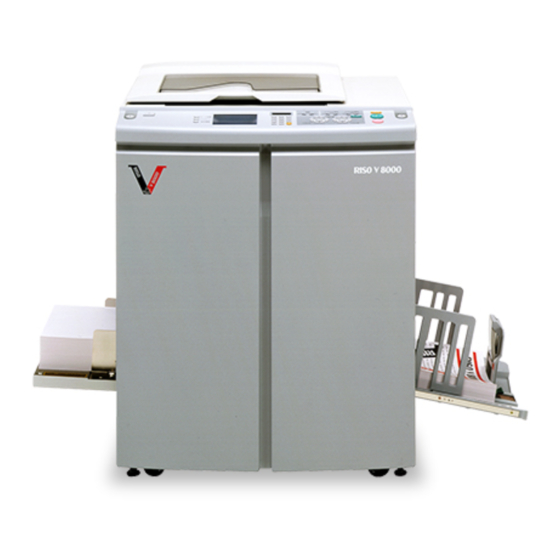
V8000
TECHNICAL MANUAL
Copyright : 2002 Riso Kagaku Corporation
All Rights Reserved. This Technical Manual was prepared and
written for the exclusive use of RISO International Group Certified
Dealers. Reproduction and/or transmittal of this material in any form
or by any means, including photocopying or recording of the
information is strictly prohibited without the consent of a member of
RISO International Group.
RISO KAGAKU CORPORATION (JAPAN)
RISO, INC. (U.S.A.)
RISO EUROPE LIMITED (U.K.)
RISO HONG KONG (HONG KONG)
RISO UK (U.K.)
RISO THAILAND LIMITED (THAILAND)
SERIES
VERSION
FEBRUARY 2002
Issued by Riso Kagaku Training Center
RISO INTERNATIONAL GROUP
RISO DEUTSCHLAND GMBH (GERMANY)
RISO FRANCE (FRANCE)
RISO IBERICA (SPAIN)
RISO CANADA (CANADA)
ZHUHAI RISO TECHNOLOGY (CHINA)
RISO AFRICA (SOUTH AFRICA)
RISOGRAPH ITALIA (ITALY)
MENU
Advertisement
Chapters
Table of Contents

Related Manuals for Riso V8000 Series


Summary of Contents for Riso V8000 Series
- Page 1 Copyright : 2002 Riso Kagaku Corporation All Rights Reserved. This Technical Manual was prepared and written for the exclusive use of RISO International Group Certified Dealers. Reproduction and/or transmittal of this material in any form or by any means, including photocopying or recording of the information is strictly prohibited without the consent of a member of RISO International Group.
-
Page 2: Table Of Contents
CONTENTS CONTENTS CHAPTER 1: MAINTENANCE Preface ........................1-2 CAUTION ........................1-3 WARNING ......................... 1-4 Work Precautions ..................... 1-5 JIGs ........................... 1-8 Installation Procedure .................... 1-11 Leveling the Machine on the Floor ................. 1-15 Exterior Cover Removal ..................1-19 CHAPTER 2: MACHINE OVERVIEW Features ........................ - Page 3 CONTENTS Disassembly .......................... 4-6 Removing the Paper Feed Cover ................4-6 Removing the Air Pump Unit ..................4-7 Removing the Pickup Roller and Scraper ..............4-8 Removing the Pickup Roller Shaft Ass’y and Paper Feed Pressure Adjustment Unit ..........................4-9 Removing the Paper Feed Tray Unit ..............
- Page 4 CONTENTS CHAPTER 6: PAPER DRUM SECTION Mechanism ..........................6-2 Paper Drum Mechanism ..................6-2 Gripper Open/Close Mechanism ................6-2 Disassembly .......................... 6-3 Removing the Paper Drum ..................6-3 Removing the Gripper Cover Ass’y ................6-6 Removing the Gripper Shaft Unit ................6-10 Removing the Gripper ...................
- Page 5 CONTENTS Adjustment .......................... 7-14 Pinch Roller Position Adjustment ................. 7-14 Paper Ejection Separator Gap Adjustment ............7-14 CHAPTER 8: PRINT DRUM SECTION Mechanism ..........................8-2 Print Drum Layout and Angle ..................8-2 Print Drum Retaining Joint Mechanism ..............8-2 Print Drum Horizontal Movement Mechanism ............8-2 Print Drum Removal/Insertion Mechanism ..............
- Page 6 CONTENTS Adjustment .......................... 8-40 Inner Pressure Roller Gap Adjustment ..............8-40 Print Density Adjustment ..................8-42 Master Elongation Adjustment ................8-42 Master Shift Adjustment ..................8-43 CHAPTER 9: VERTICAL PRINT POSITION SECTION Mechanism ..........................9-2 Vertical Print Position Mechanism ................9-2 Disassembly ..........................
- Page 7 CONTENTS Disassembly ........................11-4 Removing the 1st Master Disposal Unit ..............11-4 Removing the Disposal Box Empty Detection Sensor (Receive) and (Send) ..11-5 Removing the Master Tail Clamp Fan (1st Master Disposal Unit Only) ....11-5 Removing the Master Disposal Motor Limit Sensor ..........11-6 Removing the Master Compression Limit Sensor and Master Compression HP Sensor ......................
- Page 8 CONTENTS CHAPTER 13: AF SCANNING SECTION Mechanism ......................... 13-2 AF Original Set Mechanism ................... 13-2 AF Original Scanning Mechanism (with Auto Base Control) ........ 13-4 AF Original Scanning Mechanism ................. 13-4 Removal and Assembly ..................... 13-6 Removing the Original Pickup Roller Ass’y ............13-6 Removing the Original Pickup Roller ..............
- Page 9 CONTENTS 12. Removing the Master Loading Motor ..............14-18 13. Removing the Master Disposal Fan and Write Roller Temperature Sensor ..14-19 14. Removing the Cutter Unit ..................14-20 Adjustment ........................14-21 Master Leading Clamp Range Adjustment ............14-21 Master Tail Clamp Range Adjustment ..............14-21 Write Start Position Adjustment ................
- Page 10 CONTENTS D01 D02 D03 D10 D11 D13 D16 D18 D19 D20 D26 D27 D28 D29 E01 E02 F01 F02 F03 F04 F10 F14 F23 F25 F27 F28 F30 F32 F35 F36 G001 G002 G004 G008 G016 Errors Requiring Special Action ................16-36 CHAPTER 17: TEST MODE Procedures ......................
- Page 11 CONTENTS CHAPTER 20: PRINTED CIRCUIT BOARDS Connection Diagram Between Boards ..............20-2 PCBs ........................20-3 2 - 1 - 1. Power Supply PCB ................20-3 2 - 1 - 2. Power Supply PCB and Fuse Compatibility Chart ....... 20-4 2 - 2 - 1. SH-PCB ....................
- Page 12 CHAPTER : MAINTENANCE Contents Preface ........................1-2 CAUTION ........................1-3 WARNING ......................... 1-4 Work Precautions ..................... 1-5 JIGs ........................... 1-8 Installation Procedure .................... 1-11 Leveling the Machine on the Floor ................. 1-15 Exterior Cover Removal ..................1-19 [1 - 1]...
-
Page 13: Chapter 1: Maintenance
CHAPTER 1. MAINTENANCE Preface This manual provides Technical Service Information for model V8000 series. This manual also provides procedures for removing and installing major components. Following these procedures will minimize machine malfunctions. The information will also increase technical represen- tatives' awareness and experience regarding repairs necessary to insure end-user satisfaction. -
Page 14: Caution
CHAPTER 1. MAINTENANCE CAUTION [Handling of Lithium Battery] - Never fail to follow the following instructions when you discard the used lithium battery. 1. Never let the battery short-circuited. If the (+) and (-) terminals contact each other or metal materials, the battery will be short-circuited. -
Page 15: Warning
CHAPTER 1. MAINTENANCE !! WARNING !! Important Safety Precautions 1. Always disconnect electrical supply before placing hands in the machine. I. To avoid injuries: Be sure to disconnect the electrical power before disassembling, assembling,or when making adjustments on the machine. II. -
Page 16: Work Precautions
CHAPTER 1. MAINTENANCE Work Precautions Inspection If you discover any defects or problems during an inspection, fix the problems or if necessary take steps such as replacing a part. Removal Check the problem area. At the same time, examine the cause of the problem and determine whether the part needs to be removed or disassembled. - Page 17 CHAPTER 1. MAINTENANCE Electrical system work • After removing wire bundles, fasten them with wire bundle bands (bar lock ties) so that they will not sag. • When installing parts, be careful to avoid pinching or damaging the wire bundles. •...
- Page 18 CHAPTER 1. MAINTENANCE Installation location • Do not install the machine in any of the following locations. Those subject to direct sunlight or any bright location such as by a window (If you must install in such a location, put a curtain or the like over the window.) Those where the temperature changes drastically Those that are too hot, cold, humid, or dry RECOMMENDED:...
-
Page 19: Jigs
CHAPTER 1. MAINTENANCE JIGs S0101 S0102 016-16141-003 022-18401-000 8 mm dia. x 160 mm shaft (JIG) 14 mm diameter long-shaft (JIG) (2 pieces required) S0103 S0104 022-18402-006 022-76001-003 8 mm diameter long-shaft (JIG) Squeegee Gap Adjustment Shaft (JIG) S0105 S0106 015-36311-005 022-16714-000 Squeegee Gap Gauge (JIG) - Page 20 CHAPTER 1. MAINTENANCE S0108 S0107 022-76002-000 Drum Joint Alignment Lock (JIG) 022-76003-006 Drum Stand (JIG) P0109 018-16255-208 Blance Weight; FB Three pieces of the part is formed into one unit, with one of the weight facing the other way P0110 030-90010-050 LED Unit S0111...
- Page 21 CHAPTER 1. MAINTENANCE 022-75000-054 Leveling jig P0128 Instructions for assembling the Leveling Jig 1. Swing open the plate indicated as B on above sketch until the pivot portion of the plate hits firmly against the plate indicated as A. Plates A and B should make one straight line. Tighten the two screws. 2.
- Page 22 CHAPTER 1. MAINTENANCE [1 - 11]...
- Page 23 CHAPTER 1. MAINTENANCE [1 - 12]...
- Page 24 CHAPTER 1. MAINTENANCE [1 - 13]...
- Page 25 CHAPTER 1. MAINTENANCE [1 - 14]...
-
Page 26: Leveling The Machine On The Floor
CHAPTER 1. MAINTENANCE Leveling the Machine on the Floor (1) Assemble the Leveling jig. < Rear side of the machine > (2) Slide open the Master making unit and mount the Leveling jig on the top thin surface of the machine frame, as shown on the photograph below. - Page 27 CHAPTER 1. MAINTENANCE (4) Look at the scale straight at right angle and read the line on the scale to which the string points to. Note: Incorrect reading of the scale will be made if the scale is viewed at an angle. The view must be made at 90 degrees against the scale.
- Page 28 CHAPTER 1. MAINTENANCE (6) Lift the Operation Panel gently upwards a little and slide it towards the front to allow the top thin surface of the machine frame to appear. (7) Remove the Leveling jig from the rear machine frame and mount it on the front machine frame in the same manner as done on the rear machine frame.
- Page 29 CHAPTER 1. MAINTENANCE (10) If the difference is more than 0.5 mm between the front and rear, attach two Height adjusters under the front of the machine, firmly against the bracket of the two casters on the machine. The Height adjusters need not be placed on the rear of the machine.
- Page 30 CHAPTER 1. MAINTENANCE Removing Exterior Covers Rear cover Rear cover P0112 [1 - 19]...
- Page 31 CHAPTER 1. MAINTENANCE Front doors, L/R Front door, L Front door, R P0113 P0114 P0115 P0116 [1 - 20]...
- Page 32 CHAPTER 1. MAINTENANCE Upper interior cover Upper interior cover P0117 Lower interior cover P0118 Lower interior cover [1 - 21]...
- Page 33 CHAPTER 1. MAINTENANCE Master disposal exterior cover F cover L Rear left cover FB left cover Paper feed cover FB left cover Master disposal exterior cover Rear left cover F cover L P0119 Paper feed cover [1 - 22]...
-
Page 34: Exterior Cover Removal
CHAPTER 1. MAINTENANCE Master making unit cover Master disposal exterior cover F cover R Rear right cover FB right cover FB handle cover FB handle cover Master making unit cover Master disposal FB right cover exterior cover F cover R Rear right cover P0120 [1 - 23]... - Page 35 CHAPTER 1. MAINTENANCE To remove the FB right cover, remove the FB lock plate front and FB safety SW Assy, slide the scanner table in the reverse direction, and remove the hidden screws. FB lock plate front FB safety SW Assy P0121 P0122 P0123...
- Page 36 CHAPTER 1. MAINTENANCE Scanner table cover FB front cover FB rear cover FB rear cover Scanner table cover P0126 FB front cover Scanner table cover hinges P0127 Original alignment sheet [1 - 25]...
-
Page 37: Chapter 2: Machine Overview
CHAPTER : MACHINE OVERVIEW Contents Features ........................2-2 Specifications ......................2-3 Product Configuration ....................2-4 Schematic Cross-Sectional View ................2-5 [2 - 1]... -
Page 38: Features
Simultaneously prints two colors at speeds up to 120 sheets per minute. The RISO V8000 uses its screen printing system to achieve both speed and economy in printing. The two print drums print simultaneously for easy two-color printing at speeds of 120 sheets per minute. -
Page 39: Specifications
CHAPTER 2. MACHINE OVERVIEW pecifications Processing Automatic digital scanning/thermal screening, high-speed twin-cylinder (drum) dual-color printing system Initial Imaging Time Letter or A4 original : approx. 90 sec. Print Speed 5 selectable levels (60 to 120 copies/min.) Scanning Resolution 600 x 600 dpi Original Input Type Bound document or sheets Original Size... -
Page 40: Product Configuration
• Inkless print drum (with case) • Card counter IV • Job separator IV • RISORINC-NET-B Consumable items • RISO master V type (1 roll, approx. 200 masters) • RISO ink V type (black) • RISO ink V type (color) [2 - 4]... -
Page 41: Schematic Cross-Sectional View
CHAPTER 2. MACHINE OVERVIEW Schematic Cross-Sectional View View of the Paper Drum and Print Drums in the “Idle” position after the printing. The Paper Drum is at 150 degrees from the T-Position. (Test mode No. 567 will also bring the machine to this position). S0201 [2 - 5]... - Page 42 CHAPTER 2. MACHINE OVERVIEW MEMO [2 - 6]...
-
Page 43: Chapter 3: Main Drive Section
CHAPTER : MAIN DRIVE SECTION Contents Mechanism ..........................3-2 Main Drive Section Rotating Mechanism ..............3-2 Main Motor Safety Mechanism .................. 3-4 Paper Drum Rotation Position ................. 3-6 Low Temperature Printing Speed Limit ..............3-6 Disassembly .......................... 3-7 Removing the Main Cover Ass’y ................3-7 Removing the Paper Feed Intermediate Gear, Pump Gear, and Guide Gear .. -
Page 44: Mechanism
CHAPTER 3. MAIN DRIVE SECTION Mechanism Main Drive Section Rotating Mechanism The print drum and paper drum are rotated for normal use by the main motor. The main motor limit sensor (encoder sensor) detects the main motor speed and the amount of rotation and verifies stable motor operations. - Page 45 CHAPTER 3. MAIN DRIVE SECTION Main motor limit (encoder) sensor Main pulse motor P0302 Main clutch Main motor Main motor P0303 Main motor gear [3 - 3]...
-
Page 46: Main Motor Safety Mechanism
CHAPTER 3. MAIN DRIVE SECTION Main Motor Safety Mechanism To ensure operator safety, six safety switches listed below prevent main motor operation if any one of the switchs are not activated. 1. Master disposal box 1 safety switch 2. Master disposal box 2 safety switch 3. - Page 47 CHAPTER 3. MAIN DRIVE SECTION P0306 Scanner table safety switch P0324 Paper ejection unit safety switch P0307 P0308 Front door safety switch (Right) Front door safety switch (Left) [3 - 5]...
-
Page 48: Paper Drum Rotation Position
CHAPTER 3. MAIN DRIVE SECTION Paper Drum Rotation Position The paper drum rotation position is checked by the Position T sensor. The precise rotational position of the paper drum is checked by the main motor limit sensor (encoder sensor) from the T-position. The Paper Drum stops at 150 degrees from its T-position after the printing job is finished and waits for next job. -
Page 49: Disassembly
CHAPTER 3. MAIN DRIVE SECTION Disassembly Removing the Main Cover Ass’y (1) Remove the reuse band on the position T sensor wire harness and disconnect the position T sensor connector. (2) Detach the wire harness from the wire saddle. (3) Remove the eight mounting screws (M4 x 8), then remove the main cover ass’y. Main cover ass’y Position T sensor P0309... -
Page 50: Removing The Paper Feed Intermediate Gear, Pump Gear, And Guide Gear
CHAPTER 3. MAIN DRIVE SECTION Removing the Paper Feed Intermediate Gear, Pump Gear, and Guide Gear (1) Remove the blind plate. (M4 x 6 screw) (2) Remove the SH-PCB+graphic board together with the mounting bracket. (Two M4 x 8 screws, four M3 x 6 screws) (3) Remove the main cover ass’y. - Page 51 CHAPTER 3. MAIN DRIVE SECTION Paper feed clutch Reinforcing plate P0313 Guide lever assembly Paper pass guide link arm Guide gear Guide lever spring P0314 Paper drum gear Intermediate gear Guide gear P0315 Paper intermediate gear Pump gear [3 - 9]...
- Page 52 CHAPTER 3. MAIN DRIVE SECTION [Precautions for Reassembly] • Align the gear phases when reassembling. Insert the dia. 8 JIG in the alignment hole in the paper drum gear. Align the marking on the intermediate gear with the marking on the paper drum gear before mounting.
-
Page 53: Removing The Main Motor Unit
CHAPTER 3. MAIN DRIVE SECTION Removing the Main Motor Unit (1) Remove the blind plate. (M4 x 6 screw) (2) Remove the SH-PCB+graphic board together with the bracket. (Two M4 x 8 screws, four M3 x 6 screws) (3) Disconnect the connector, detach the E-ring, and remove the paper feed clutch. (4) Remove the guide lever spring. - Page 54 CHAPTER 3. MAIN DRIVE SECTION MEMO [3 - 12]...
- Page 55 CHAPTER : FIRST PAPER FEED SECTION Contents Mechanism ..........................4-2 Paper Feed Tray Mechanism ................... 4-2 Paper Feed Tray Elevation Mechanism ..............4-4 First Paper Feed Mechanism ................... 4-4 Paper Strip Mechanism .................... 4-5 Disassembly .......................... 4-6 Removing the Paper Feed Cover ................4-6 Removing the Air Pump Unit ..................
-
Page 56: Chapter 4: First Paper Feed Section
CHAPTER 4. FIRST PAPER FEED SECTION Mechanism Paper Feed Tray Mechanism Dampers are fitted to both sides of the paper feed tray to ensure that it opens gently. The paper feed tray set sensor checks that the paper feed tray is in place. The horizontal print position is adjusted using the print drum so the paper feed tray does not move sideways. - Page 57 CHAPTER 4. FIRST PAPER FEED SECTION < Damper on the operator side of the paper feed tray > VIEW FROM THE ARROW MARK ON THE PREVIOUS PAGE Damper Paper feed tray P0430 Paper feed tray set sensor < Measured size & Determined size chart > Measured size (mm) Determined size 292 - 302...
-
Page 58: Paper Feed Tray Elevation Mechanism
CHAPTER 4. FIRST PAPER FEED SECTION Paper Feed Tray Elevation Mechanism The paper feed tray is raised automatically at the start of printing and is lowered when there is no more paper in the paper tray and the paper detection sensor does not detect reflected light. The paper feed tray is also lowered if the feed tray button is pressed during print standby. -
Page 59: Paper Strip Mechanism
CHAPTER 4. FIRST PAPER FEED SECTION Paper Strip Mechanism The paper loaded into the paper feed tray is fed in between the pickup roller and the stripper pad by the rotation of the scraper. The paper is stripped by the pickup roller and stripper pad to ensure that only the top single sheet is fed into the machine. -
Page 60: Disassembly
CHAPTER 4. FIRST PAPER FEED SECTION Disassembly Removing the Paper Feed Cover (1) Completely lowerhepaper feed tray. (2) Remove the four mounting screws (M4 x 8), disconnect the connector on the paper feed tray safety switch wire harness, and remove the paper feed cover. * Note the position of the pressure adjust lever. -
Page 61: Removing The Air Pump Unit
CHAPTER 4. FIRST PAPER FEED SECTION Removing the Air Pump Unit (1) Remove the paper feed cover. (2) Remove the nozzle. (M4 x 8 screw) (3) Loosen the hose band, detach the hose from the nozzle, then pull outside the side panel (front). (4) Detach the E-ring on the air pump cam plate, remove the four mounting screws (M4 x 8) on the pump unit, and remove the pump unit. -
Page 62: Removing The Pickup Roller And Scraper
CHAPTER 4. FIRST PAPER FEED SECTION Removing the Pickup Roller and Scraper Removing the scraper (1) Completely lower the paper feed tray and switch off power. (2) Remove the lock ring on the end of the scraper shaft. (3) Remove the scraper from the scraper shaft. Removing the pickup roller (1) Completely lower the paper feed tray and switch off power. -
Page 63: Removing The Pickup Roller Shaft Ass'y And Paper Feed Pressure Adjustment Unit
CHAPTER 4. FIRST PAPER FEED SECTION Removing the Pickup Roller Shaft Ass’y and Paper Feed Pressure Adjustment Unit (1) Remove the paper feed cover. (2) Detach the E-ring, disconnect the connector, then remove the paper feed clutch. (3) Remove the E-rings and bearing bushes on both sides of the pickup roller shaft. Remove the pickup roller shaft ass’y. -
Page 64: Removing The Paper Feed Tray Unit
CHAPTER 4. FIRST PAPER FEED SECTION Removing the Paper Feed Tray Unit (1) Completely lower the paper feed tray. (2) Remove the wire harness cover (white plastic plate). (Two M4 x 8 screws) (3) Detach the reuse band on the paper feed tray wire harness, disconnect the connector, and remove the ground wire retaining screw (M4 x 8). -
Page 65: Removing The Paper Guide Fence
CHAPTER 4. FIRST PAPER FEED SECTION Removing the Paper Guide Fence (1) Loosen the set screw, rotate the fence lock knob, and remove the fence lock shaft. (2) Remove the two mounting screws (M3 x 6) on each side and remove the left and right paper guide fences. -
Page 66: Removing The Paper Detection Sensor, Paper Size Detection Sensor, And Paper Width Potentiometer
CHAPTER 4. FIRST PAPER FEED SECTION Removing the Paper Detection Sensor, Paper Size Detection Sensor, and Paper Width Potentiometer (1) Remove the seven mounting screws (M3 x 6) from the paper feed tray unit. Remove the paper feed tray cover. Paper Detection Sensor (2) Disconnect the connector, remove the mounting screw (M3 x 14), and remove the paper detection sensor. - Page 67 CHAPTER 4. FIRST PAPER FEED SECTION Paper detection sensor Paper width potentiometer P0416 P0417 P0418 P0419 Paper size detection sensor Paper width potentiometer P0420 [4 - 13]...
-
Page 68: Removing The Center Gear
CHAPTER 4. FIRST PAPER FEED SECTION Removing the Center Gear (1) Remove the paper feed tray. (2) Remove the paper guide fences. (3) Remove the paper feed tray cover. (4) Remove the paper width potentiometer. (5) Remove the paper feed tray reinforcing plate. (Four M4 x 8 screws) (6) Remove side frames F and R. - Page 69 CHAPTER 4. FIRST PAPER FEED SECTION P0422 Shaft (center) Adjoining component Adjoining component Shafts (front/rear) Fixed shaft stud (below shaft) P0423 Fence blocks P0424 Racks Center gear [4 - 15]...
-
Page 70: Removing The Elevator Motor
CHAPTER 4. FIRST PAPER FEED SECTION Removing the Elevator Motor (1) Detach the elevator spring from theE support plate F and E support plate R. (2) Disconnect the connector, remove the mounting screw (M4 x 8), then remove the elevator motor. Elevator spring Connector P0425... -
Page 71: Removing The Elevator Lower Limit Sensor; Paper Volume Detection Sensors A And B
CHAPTER 4. FIRST PAPER FEED SECTION 10. Removing the Elevator Lower Limit Sensor; Paper Volume Detection Sensors A and B (1) Remove the control PCB. (2) Remove the paper volume detection plate. (M4 x 8 screw) (3) Disconnect the connector, detach the reuse band, and remove the elevator lower limit sensor plate ass’y. -
Page 72: 11. Removing The Stripper Unit
CHAPTER 4. FIRST PAPER FEED SECTION 11. Removing the Stripper Unit (1) Lower the paper-feed tray to the lower-limit position, and turn OFF the machine power. (2) Place your finger on the top of the stripper unit and pull forward to unhook the unit. (3) Unplug the connector of the multiple feed switch, and remove the stripper unit. -
Page 73: 12. Removing The Stripper-Pad Ass'y
CHAPTER 4. FIRST PAPER FEED SECTION 12. Removing the Stripper-Pad Ass’y (1) Lower the paper-feed tray to the lower-limit position, and remove the stripper unit. (2) Lift the stripper-pad ass’y by hand and remove it. Stripper-pad ass’y Stripper pad Stripper-pad base Stripper-pad cover S0430 Position the Stripper pad flat against the back... -
Page 74: Adjustment
CHAPTER 4. FIRST PAPER FEED SECTION Adjustment Paper Width Potentiometer Adjustment Check and adjustment procedure (1) Position the paper guide fences at 100 mm and run test mode No. 450 (Paper size VR adjust 100 mm). (2) Position the paper guide fences at 300 mm and run test mode No. 451 (Paper size VR adjust 300 mm). -
Page 75: Paper Limit Detection Plate Attachment
CHAPTER 4. FIRST PAPER FEED SECTION Paper Limit Detection Plate Attachment • Attach with a diameter 3 mm round shaft (or 2.5 mm Allen wrench) inserted into the paper limit detection plate slot and scraper holder plate hole, as shown in the photograph. This will position the edge of the Paper limit detection plate against the center of the three lines engraved on the Scraper holder plate. -
Page 76: Stripper Adjustment
CHAPTER 4. FIRST PAPER FEED SECTION Stripper Adjustment [Standard machines] Procedure (1) Use the pressure-adjust lever to set the most suitable paper type prior to printing. (2) If multiple feeding or misfeeding occurs, adjust the stripper-pad angle and stripper pressure. Multiple feeding •... -
Page 77: Position Of Multiple Paper Feed Switch
CHAPTER 4. FIRST PAPER FEED SECTION Position of Multiple Paper Feed Switch 1. Activate test mode No. 416, with the stripper unit attached to the main body, push down the Stripper pad slowly with a finger. After pushing them down about 0.8mm to 1.2mm, make sure that the Multiple Paper Feed switch is pressed and clicks(Fig. - Page 78 CHAPTER 4. FIRST PAPER FEED SECTION MEMO [4 - 24]...
- Page 79 CHAPTER : SECOND PAPER FEED SECTION Contents Mechanism ..........................5-2 Second Paper Feed Mechanism ................5-2 Paper Pass Guide Mechanism ................5-2 Disassembly .......................... 5-3 Removing the Paper Pass Guide ................5-3 Removing the Timing Roller Ass’y ................5-4 Removing the Guide Roller Ass’y ................5-5 Removing the 1st Paper Feed Sensor, 2nd Paper Feed Sensor, and Multiple Paper Feed Detection Sensor ..............
-
Page 80: Mechanism
CHAPTER 5. SECOND PAPER FEED SECTION Mechanism Second Paper Feed Mechanism The second paper feed mechanism is operated by the rotating timing roller (the guide roller rotates due to drag torque). Rotary drive is provided by the sector gear, which in turn is driven by the timing cam. The timing roller incorporates a one-way core that permits it to rotate when the timing gear rotates clockwise, but not when the timing gear rotates counterclockwise. -
Page 81: Disassembly
CHAPTER 5. SECOND PAPER FEED SECTION Disassembly Removing the Paper Pass Guide (1) Open the front door and pull out the 1st print drum. (2) Remove the second paper feed upper cover. (Four M4 x 8 screws) (3) Remove the 2nd paper feed sensor bracket. (M4 x 8 screw) (4) Remove the two mounting screws (M4 x 6) and remove the paper pass guide. -
Page 82: Removing The Timing Roller Ass'y
CHAPTER 5. SECOND PAPER FEED SECTION Removing the Timing Roller Ass’y (1) Open the front door and pull out the 1st print drum. (2) Remove the covers. (3) Remove the second paper feed upper cover. (4) Remove the 2nd paper feed sensor bracket. (5) Remove the two mounting screws (M4 x 8), then remove the timing clutch bracket. -
Page 83: Removing The Guide Roller Ass'y
CHAPTER 5. SECOND PAPER FEED SECTION Removing the Guide Roller Ass’y (1) Lower the paper feed tray fully and remove the covers. (2) Remove the following components. • Pickup roller and scraper • Stripper unit • Paper feed tray unit •... - Page 84 CHAPTER 5. SECOND PAPER FEED SECTION (6) Detach the two springs on the guide roller ass’y. (7) Remove the guide lever spring. (8) Detach the E-ring and remove the paper pass guide link arm. (9) Remove the paper pass guide lever ass’y. (M4 x 8 screw) (10) Rotate the paper drum by hand to position the guide lever ass’y at the bottom of the cam on the guide roller gear.
- Page 85 CHAPTER 5. SECOND PAPER FEED SECTION (13) Disconnect the wire harness connector, detach from the wire saddles, and remove the guide plate lower ass’y. (Four M4 x 8 screws) (14) Detach the E-rings and metals on both sides and remove the guide roller ass’y with the two springs still attached.
-
Page 86: Removing The 1St Paper Feed Sensor, 2Nd Paper Feed Sensor, And Multiple Paper Feed Detection Sensor
CHAPTER 5. SECOND PAPER FEED SECTION Removing the 1st Paper Feed Sensor, 2nd Paper Feed Sensor, and Multiple Paper Feed Detection Sensor P0515 Guide plate lower ass’y (upper surface) 1st paper feed sensor (receive) P0516 P0517 2nd paper feed sensor bracket [5 - 8]... - Page 87 CHAPTER 5. SECOND PAPER FEED SECTION P0518 Guide plate lower ass’y (bottom view) 2nd paper feed sensor (send) Multiple paper feed detection sensor (receive) P0519 1st paper feed sensor (send) [5 - 9]...
-
Page 88: Adjustment
CHAPTER 5. SECOND PAPER FEED SECTION Adjustment Gap Between Timing Roller and Guide Roller Check and adjustment procedure (1) Rotate the paper drum until the cam on the guide roller gear is positioned as shown in the diagram. (2) Check that the gap between the guide roller and the timing roller is 1.0 mm ± 0.25 mm. (3) If the gap size falls outside these specified values, loosen the guide lever ass’y lock screw and adjust. -
Page 89: Gap Between Paper Pass Guide And Lower Paper Guide
CHAPTER 5. SECOND PAPER FEED SECTION Gap Between Paper Pass Guide and Lower Paper Guide Check and adjustment procedure (1) Rotate the paper drum until the cam on the guide roller gear is positioned as shown in the diagram. (2) Check that the gap between the paper pass guide ass’y and the lower guide plate is 1.0 mm ±... -
Page 90: Nd Paper Feeding Adjustment
CHAPTER 5. SECOND PAPER FEED SECTION 2nd Paper Feeding Adjustment Check and adjustment procedure (1) Affix adhesive tape over the gripper cover (to prevent the paper from being gripped). (2) Load standard paper (A3) in the paper feed tray. (3) Feed paper using Test mode No. 464 (2nd paper feeding adjustment). (4) Measure the distance between the leading edge of the paper and the leading edge of the Cover Sheet on the paper drum (Dimension A) at the paper position by above step (3), confirming that it is between 9 mm ±... -
Page 91: Automatic Multiple Paper Feed Adjustment
CHAPTER 5. SECOND PAPER FEED SECTION Vertical Print Position Variation Check (Print Registration) (1) Run Test mode No. 051 (TPH test print with thin cross lines) for 1st and 2nd print drums. (2) Shift the horizontal printing position maximum to the machine drive side (left) on the 1st print drum. (3) Shift the horizontal printing position maximum to the machine operation side (right) on the 2nd print drum. - Page 92 CHAPTER 5. SECOND PAPER FEED SECTION MEMO [5 - 14]...
- Page 93 CHAPTER : PAPER DRUM SECTION Contents Mechanism ..........................6-2 Paper Drum Mechanism ..................6-2 Gripper Open/Close Mechanism ................6-2 Disassembly .......................... 6-3 Removing the Paper Drum ..................6-3 Removing the Gripper Cover Ass’y ................6-6 Removing the Gripper Shaft Unit ................6-10 Removing the Gripper ...................
-
Page 94: Mechanism
CHAPTER 6. PAPER DRUM SECTION Mechanism Paper Drum Mechanism For normal rotation, the paper drum is driven by the main motor; for master loading and super low speed rotation, it is driven by the main pulse motor. The position of the paper drum is determined by the position T sensor. The precise position of the paper drum is confirmed by the main motor limit sensor using the position from position T sensor as a datum position. -
Page 95: Disassembly
CHAPTER 6. PAPER DRUM SECTION Disassembly Removing the Paper Drum (1) Pull out 1st and 2nd print drums. (2) Detach the lock ring and remove the handle. (3) Remove the following covers. • Front doors (left/right) • Front cover (lower) •... - Page 96 CHAPTER 6. PAPER DRUM SECTION (7) Rotate the paper drum to insert 8 mm diameter shaft (JIG) into the main cover alignment hole and rear paper drum gear, and lock the paper drum gear in position. (8) Remove the paper drum lock screw (M6 x 20) in the center of the paper drum gear. (9) Remove the gripper cover cam.
- Page 97 CHAPTER 6. PAPER DRUM SECTION [Precautions for Reassembly] • Align the paper drum coupling protrusions with the slots in the paper drum gear. • When installing the paper drum, close the grippers and gripper cover and secure with adhesive tape in the same way as when removing. •...
- Page 98 CHAPTER 6. PAPER DRUM SECTION Removing the Gripper Cover Assembly (1) Remove the paper drum from the machine. (2) Remove the adhesive tape from the gripper cover ass’y and open the gripper cover. (3) Remove the link spring from the rear of the paper drum. <Instructions to follow are for the front portion of the paper drum.>...
- Page 99 CHAPTER 6. PAPER DRUM SECTION Gripper cover ass’y Cover stay Gripper plate F ass’y P0615 P0616 Gripper Gripper cover ass’y P0617 (Enlarged view) <Positioning the Cover sheet over the Gripper cover ass’y> Refer to the following sketch in positioning the cover sheet over the gripper cover ass’y. The A and B marked lines on the sketch should align between the cover sheet and the gripper cover ass’y.
- Page 100 CHAPTER 6. PAPER DRUM SECTION Assembling back the gripper cover assembly (1) Fit the 8 mm diameter long-shaft (JIG) through the gripper plate R ass’y, paper drum side plate (R), paper drum side pate (F), and gripper plate F ass’y. (2) Insert the shaft of the gripper cover ass’y through the hole with the brass metal on the gripper plate ass’y F and R.
- Page 101 CHAPTER 6. PAPER DRUM SECTION Paper lifter Link cover F ass’y P0621 3 mm Allen wrench Adhesive tape Gripper cover ass’y P0622 [6 - 9]...
-
Page 102: Removing The Gripper Shaft Unit
CHAPTER 6. PAPER DRUM SECTION Removing the Gripper Shaft Unit (1) Remove gripper cover ass’y. (Refer to page No. 6-6) (2) Remove cover stay (cap screw M4x8, spring washer, and plain washer). (3) Remove paper lifter timing plate ass’y (M3x6 screw) from the rear of the paper drum. (4) Remove BB roller (one E-ring) from the rear of the paper drum. - Page 103 CHAPTER 6. PAPER DRUM SECTION (6) Remove E-ring and one screw (M3x6) to detach paper drum timing gear R ass’y from the rear of the paper drum. (7) Detach gripper cover shaft by removing metal shaft bearings from the front and rear of the paper drum.
- Page 104 CHAPTER 6. PAPER DRUM SECTION (10) Remove the screws holding the gripper shaft reinforcing arm. (two M4x12 screws) (11) Remove gripper gear from the gripper shaft unit. (M3x6 screw) (12) Remove metal shaft bearing from the rear of the gripper shaft unit. (13) Remove E-ring and metal shaft bearing from the front of the gripper shaft unit.
- Page 105 CHAPTER 6. PAPER DRUM SECTION Gripper shaft unit Gripper collar < FRONT > < REAR > P0630 P0631 Gripper shaft unit [6 - 13]...
- Page 106 CHAPTER 6. PAPER DRUM SECTION Assembling back the gripper shaft unit (1) Fit the gripper shaft unit back on the paper drum. (2) Mount the gripper gear on the machine rear side of the griper shaft unit. The groove on the gripper gear should face outside. (3) Mount the gripper cover shaft, together with the metal bearings on the front and rear.
- Page 107 CHAPTER 6. PAPER DRUM SECTION (6) Fit the 8 mm diameter long-shaft (JIG) through the gripper plate R ass’y, paper drum side plate (R), paper drum side pate (F), and gripper plate F ass’y. (7) Attach paper drum timing gear R ass’y on the paper drum. Use an available 3 mm diameter rod or 2.5 mm Allen wrench to align the elongated hole on the paper drum timing gear R ass’y and round hole on the gripper gear to achieve correct positioning.
- Page 108 CHAPTER 6. PAPER DRUM SECTION (8) Mount the gripper spring hook plate, and hook the nine gripper springs. (9) Insert the shaft of the gripper ass’y and cover stay through the holes on the gripper plate ass’y F & R, and attach screws on both ends of the cover stay. The shaft on the cover stay with a flat cut should go on the rear of the paper drum.
-
Page 109: Removing The Gripper
CHAPTER 6. PAPER DRUM SECTION Removing the Gripper (1) Remove gripper shaft unit. (2) Remove gripper collar. (3) Remove gripper base (M3x8 screw each). (4) Remove the grippers from gripper shaft. [Precautions on Reassembly] • Do not make mistake in the direction of the gripper shaft and gripper shaft spring during the assembly. -
Page 110: Removing The Paper Lifter
CHAPTER 6. PAPER DRUM SECTION Removing the Paper Lifter (1) Remove gripper shaft unit. (2) Remove paper lifter spring. (3) Since paper lifter ass’y cannot be detached, remove only the paper lifter by removing four screws. Paper lifter spring P0644 Paper lifter Paper lifter ass’y P0645... -
Page 111: Adjustment
CHAPTER 6. PAPER DRUM SECTION Adjustment Position T Sensor Adjustment (1) Start up Test mode. (2) Rotate the paper drum to position T and insert 8 mm diameter long-shaft (JIG) through the front frame plate, paper drum, and rear frame plate, in this sequence. (3) Run Test mode No. - Page 112 CHAPTER 6. PAPER DRUM SECTION MEMO [6 - 20]...
- Page 113 CHAPTER : PAPER EJECTION SECTION Contents Mechanism ..........................7-2 1. Paper Ejection Mechanism ..................7-2 2. Pinch Roller Mechanism ..................7-2 3. Pinch Roller Positioning Mechanism ............... 7-2 4. Pinch Roller Ass’y Home Position and Movement ..........7-3 5. Paper Receiving Tray Mechanism ................7-3 Disassembly ..........................
-
Page 114: Mechanism
CHAPTER 7. PAPER EJECTION SECTION Mechanism Paper Ejection Mechanism The paper transferred from the paper drum is ejected to the paper receiving tray, as described below. (1) The leading edge of the paper is released from the paper drum grippers while pinched between the paper drum and the first pinch roller. -
Page 115: Pinch Roller Ass'y Home Position And Movement
CHAPTER 7. PAPER EJECTION SECTION Pinch Roller Ass’y Home Position and Movement The F/R pinch sensor detects the home position of the two pinch roller assemblies. When power is switched on or pressing the All Reset Button moves the pinch roller ass’y s to the home position. -
Page 116: Disassembly
CHAPTER 7. PAPER EJECTION SECTION Disassembly Removing the Paper Receiving Tray (1) Remove the receiving tray lock plates on both sides. (M3 x 6 screw on each side) (2) Remove the paper receiving tray from the paper receiving tray support ass’y . Paper receiving tray support ass’y Receiving tray lock plate... -
Page 117: Removing The Paper Ejection Pinch Unit
CHAPTER 7. PAPER EJECTION SECTION Removing the Paper Ejection Pinch Unit (1) Remove the four mounting screws (M4 x 6). Remove the paper ejection pinch unit from the receiving tray slide rail. Paper ejection pinch unit Receiving tray slide rail P0703 Removing the Paper Receiving Tray Support Ass’y (1) Remove the four mounting screws (M4 x 6) and remove the paper receiving tray support ass’y from... -
Page 118: Removing The Paper Ejection Cover Ass'y
CHAPTER 7. PAPER EJECTION SECTION Removing the Paper Ejection Cover Ass’y (1) Remove the five mounting screws (M4 x 8), pull out the paper ejection cover ass’y toward the paper ejection side, and disconnect the paper ejection sensor (send) connector (at the rear) before removing the paper ejection cover Ass’y . -
Page 119: Removing The Paper Ejection Roller Unit
CHAPTER 7. PAPER EJECTION SECTION Removing the Paper Ejection Roller Unit (1) Remove the paper ejection cover ass’y . (2) Disconnect the two connectors, remove the four mounting screws (M4 x 8) and remove the paper ejection roller unit. P0708 P0709 Paper ejection roller unit Removing the Paper Ejection Motor... -
Page 120: Removing The Paper Ejection Limit Sensor
CHAPTER 7. PAPER EJECTION SECTION Removing the Paper Ejection Limit Sensor Paper ejection limit sensor (encoder sensor) P0712 Paper ejection motor Removing the Pinch Rollers (1) Remove the paper ejection pinch unit. (2) Detach the E-ring, pull out the pinch roller shaft from the pinch slide plate and remove the spacer and pinch roller. -
Page 121: Removing The Pinch Slide Ass'y
CHAPTER 7. PAPER EJECTION SECTION 10. Removing the Pinch Slide Ass’y (1) Remove the paper ejection pinch unit. (2) Remove the pinch cover. (Six M4 x 8 screws) (3) Detach the pinch release springs (front and rear) and disconnect the connectors to the motor and sensor at the front and rear. - Page 122 CHAPTER 7. PAPER EJECTION SECTION 11. Removing the Pinch Pulse Motors F & R (FRONT) (REAR) (1) Remove the pinch slide ass’y . (2) From both ends of the pinch slide ass’y , remove the two mounting screws (M3 x 6), and detach the pinch pulse motor timing belt.
-
Page 123: Removing The Paper Ejection Sensor (Receive)
CHAPTER 7. PAPER EJECTION SECTION 13. Removing the Paper Ejection Sensor (Receive) (1) Remove the paper ejection pinch unit. (2) Remove the pinch slide ass’y from the pinch base ass’y . (3) Disconnect the connector and remove the paper ejection sensor (receive) together with its bracket from the pinch base ass’y . -
Page 124: Removing The Pinch Roller Release Motor
CHAPTER 7. PAPER EJECTION SECTION 15. Removing the Pinch Roller Release Motor (1) Remove the lower pinch base plate. (Three M3 x 6 screws) (2) Release the wire harness from the two wire saddles and disconnect the pinch roller release motor connector. -
Page 125: Removing The Pinch Roller Release Sensor
CHAPTER 7. PAPER EJECTION SECTION 16. Removing the Pinch Roller Release Sensor (1) Remove the pinch roller release ass’y and pinch release shaft ass’y . (2) Disconnect the connector. Remove the pinch roller release sensor. P0728 Pinch roller release sensor [7 - 13]... -
Page 126: Adjustment
CHAPTER 7. PAPER EJECTION SECTION Adjustment Pinch Roller Position Adjustment (1) Apply a marking agent to the pinch rollers and feed paper between them. (2) Measure the width of the marks for the front and rear rollers, confirming that this is 3 mm ± 0.5 mm. (3) If the pinch roller mark width falls outside the specifications, correct by running Test mode No. - Page 127 CHAPTER : PRINT DRUM SECTION Contents Mechanism ..........................8-2 Print Drum Layout and Angle ..................8-2 Print Drum Retaining Joint Mechanism ..............8-2 Print Drum Horizontal Movement Mechanism ............8-2 Print Drum Removal/Insertion Mechanism .............. 8-3 Master on Drum (Before Printing) Check Mechanism ..........8-3 Ink Cartridge Set Mechanism ...................
-
Page 128: Mechanism
CHAPTER 8. PRINT DRUM SECTION Mechanism Print Drum Layout and Angle The two interchangeable print drums have the identical construction. When mounted in the machine, the drum closest to the paper feed side is called the 1st print drum, while the one at the paper ejection side is called the 2nd print drum. -
Page 129: Print Drum Removal/Insertion Mechanism
CHAPTER 8. PRINT DRUM SECTION Print Drum Removal/Insertion Mechanism The print drum is removed and inserted with the print drum at position B. When removing the print drum from the machine, the B position is 13° print drum turn from the position in which the position B lock confirmation sensor on the print drum detects the position A detection plate. -
Page 130: Ink Cartridge Set Mechanism
CHAPTER 8. PRINT DRUM SECTION Ink Cartridge Set Mechanism Black and color ink have different cartridge SW PCBs. Black ink: 3 sensors. Color ink: 3 sensors. The sensors check that the correct ink cartridges are inserted. Ink cartridge set switches 1 to 3 check whether the ink cartridges matching the print drum are in placed in the printing drums. -
Page 131: Print Drum Lock Mechanism
CHAPTER 8. PRINT DRUM SECTION Print Drum Lock Mechanism The print drums are locked by driving the print drum lock cam by the print drum lock motor. The position of the drum lock cam is checked by the lock cam sensor. The drum lock sensor confirms that the drum lock lever is in the lock position. -
Page 132: Disassembly
CHAPTER 8. PRINT DRUM SECTION Disassembly Removing the Screen Ass’y (1) Remove the side frame R and side frame L. (Five M4 x 8 screws on each) (2) Remove the two screen springs. (3) Remove the front and rear E-rings and washers. (Refer to the photograph below.) (4) Remove the front and rear stepped screws. - Page 133 CHAPTER 8. PRINT DRUM SECTION Hanger E Clamp plate base ass’y P08006 Screen ass’y P08007 Hanger TA [8 - 7]...
-
Page 134: Removing The Ink Volume Detection Sensor (Receive) Ass'y
CHAPTER 8. PRINT DRUM SECTION Removing the Ink Volume Detection Sensor (Receive) Ass’y (1) Remove the print drum cover. (Four M4 x 8 screws) (2) Disconnect the four connectors and two snap bands, remove the two mounting screws (M4 x 8), and remove the ink volume detection sensor (receive) ass’y. -
Page 135: Removing The Ink Volume Detection Sensor (Receive)
CHAPTER 8. PRINT DRUM SECTION Removing the Ink Volume Detection Sensor (Receive) (1) Remove the print drum cover and detach the ink volume detection sensor (receive) ass’y. (2) Open the ink volume detection sensor (receive) ass’y flat on a table, and remove the bottle end cover spring. -
Page 136: Removing The Ink Volume Detection Sensor (Send) Ass'y
CHAPTER 8. PRINT DRUM SECTION Removing the Ink Volume Detection Sensor (Send) Ass’y (1) Remove the screen ass’y. (2) Release the position-B lock plate, and rotate the flange to bring the clamp plate base ass’y to the side. (3) Loosen the four mounting screws (M4 x 6). Remove the dome sheet. (4) Disconnect the connector, remove the two mounting screws (M4 x 8) and remove the ink volume detection sensor (send) ass’y. -
Page 137: Removing The Inner Pressure Clutch
CHAPTER 8. PRINT DRUM SECTION Removing the Inner Pressure Clutch (1) Remove the print drum cover. (Four M4 x 8 screws) (2) Disconnect the connector, remove the two mounting screws (M4 x 8), and remove the inner pressure clutch. [Precautions on Reassembly] ·... -
Page 138: Removing The Horizontal Pulse Motor Ass'y
CHAPTER 8. PRINT DRUM SECTION Removing the Horizontal Pulse Motor Ass’y (1) Remove the screen ass’y. (2) Loosen the four mounting screws (M4 x 6) and remove the dome sheet. (3) Disconnect the connector, unplug two detachable wire harness bands, and remove the horizontal pulse motor ass’y by removing two mounting screws (M4 x 8). -
Page 139: Removing The Ink Pump Ass'y
CHAPTER 8. PRINT DRUM SECTION Removing the Ink Pump Ass’y (1) Remove the print drum cover. (2) Remove the screen ass’y. (3) Loosen the four mounting screws (M4 x 6) and remove the dome sheet. (4) Remove the inner pressure clutch ass’y. (5) Slide bottle guide B to one side and disconnect two connectors. -
Page 140: Removing The Pressure Control Motor
CHAPTER 8. PRINT DRUM SECTION Removing the Pressure Control Motor (1) Remove the print drum cover. (2) Remove side frames L and R. (3) Remove the screen ass’y. (4) Loosen the four mounting screws (M4 x 6) and remove the dome sheet. (5) Lower the inner pressure roller. - Page 141 CHAPTER 8. PRINT DRUM SECTION Connector P08028 Pressure control motor ass’y P08029 Pressure control motor ass’y [8 - 15]...
-
Page 142: Removing The Ink Sensor Pcb
CHAPTER 8. PRINT DRUM SECTION Removing the Ink Sensor PCB (1) Remove the print drum cover. (2) Remove the screen ass’y. (3) Loosen the four mounting screws (M4 x 6) and remove the dome sheet. (4) Remove the inner pressure clutch ass’y. (5) Disconnect the connector and remove the ink volume detection sensor (send) ass’y. - Page 143 CHAPTER 8. PRINT DRUM SECTION Bottle guide A P08032 Connector P08033 P08034 Ink sensor PCB ass’y [Precautions on Reassembly] Engage the protrusions on ink sensor PCB bracket A with the slots in ink sensor PCB bracket B. Protrusions on ink sensor PCB bracket A Slots in ink sensor PCB bracket B P08035 P08036...
-
Page 144: 10. Removing The Clamp Plate Base Ass'y
CHAPTER 8. PRINT DRUM SECTION 10. Removing the Clamp Plate Base Ass’y (1) Remove the screen ass’y. (2) Remove the four mounting screws (M4 x 8). Remove the clamp plate base ass’y. P08037 P08038 P08039 Clamp plate base ass’y [8 - 18]... -
Page 145: 11. Removing The Inner Pressure Roller Unit
CHAPTER 8. PRINT DRUM SECTION 11. Removing the Inner Pressure Roller Unit (1) Activate test mode No.558 to print and remove the ink from the Print Drum. (2) Remove the print drum from the machine. Remove the following components: · Print drum cover ·... - Page 146 CHAPTER 8. PRINT DRUM SECTION (4) Loosen two set screws and remove the spur gear from the inner pressure roller drive shaft. (5) Remove two E-rings and detach the bearing. Spur gear P08041 Flange drive gear F E-ring (2 pcs) P08042 Bearing P08043...
- Page 147 CHAPTER 8. PRINT DRUM SECTION (6) Detach the E-ring on the flange drive gear shaft and loosen the two set screws on flange drive gear F. Disconnect the connector on the inner pressure limit sensor (encoder sensor), confirming that the inner pressure detection plate is positioned in between the sensor.
- Page 148 CHAPTER 8. PRINT DRUM SECTION (7) Detach the E-rings and remove the link plate and link ass’y. E-rings P08049 Link plate Link ass’y From steps (8) to (15), which continues, are all on the rear (drive) side of the machine. (8) Remove C-ring and detach print drum rear frame ass’y.
- Page 149 CHAPTER 8. PRINT DRUM SECTION (9) Loosen two set screws and remove the spur gear. (10) Remove E-ring, two screws (M3x8), and detach one-way hinge. (11) Remove the bearing. Spur gear P08052 One-way hinge P08053 Bearing Inner pressure roller drive shaft P08054 P08055 [8 - 23]...
- Page 150 CHAPTER 8. PRINT DRUM SECTION (12) Unplug two sensor connectors and remove one detachable wire harness band. (13) Remove two mounting screws (M4 x 8) on the print drum flange R ass’y and slide the print drum flange R ass’y together with flange drive gear shaft attached to remove. Detachable wire harness band Connectors P08056...
- Page 151 CHAPTER 8. PRINT DRUM SECTION (14) Detach the E-rings and remove the link plate and link ass’y. Link ass’y Link plate P08059 E-rings [8 - 25]...
- Page 152 CHAPTER 8. PRINT DRUM SECTION (15) Detach ink shaft drive plate by removing screw (M4x8), and remove metal bearing with flange, spur gear, and then pull out the ink drive shaft. * Do not misplace the metal bearing between the spur gear and the O-ring. Metal bearing with flange Ink drive shaft P08060...
- Page 153 CHAPTER 8. PRINT DRUM SECTION (16) Detach inner pressure roller springs (one each on FRONT and REAR) and remove mounting screw (M4x8) on each side. Detach pin C on the inner pressure roller unit from the slot in the inner pressure roller support plate and remove the inner pressure roller unit.
- Page 154 CHAPTER 8. PRINT DRUM SECTION Assembling back the inner pressure roller unit (1) Mount the inner pressure roller unit. Fix the inner pressure roller unit on the print drum by two mounting screws after attaching pin C in the slot in the inner pressure roller support plate and after attaching the inner pressure roller springs.
- Page 155 CHAPTER 8. PRINT DRUM SECTION (2) Insert ink drive shaft, and mount spur gear and ink drive shaft plate. Firmly push the metal bearing and O-ring on the ink drive shaft with the spur gear for firm insertion of the O-ring. (3) Mount link plate and link ass’y on both end of the print drum.
- Page 156 CHAPTER 8. PRINT DRUM SECTION (8) Attach E-ring on the flange drive gear shaft, and then pull the flange drive gear F against the bearing and tighten the two set screws on the gear. (9) Install bearing, one-way hinge, E-ring, and spur gear on the rear side of the inner pressure roller drive shaft.
-
Page 157: 12. Removing The Engagement Pin
CHAPTER 8. PRINT DRUM SECTION 12. Removing the Engagement Pin (1) Remove following parts from the print drum. · Print drum cover · Screen ass’y · Print drum rear frame ass’y (2) Remove two mounting screws of the flange drive gear R. (Cap screw M4x8 + 4 mm spring washer) (3) Remove the engagement pin by loosening two set screws. - Page 158 CHAPTER 8. PRINT DRUM SECTION Assembling back the engagement pin (1) Slide 8 mm diameter long-shaft (JIG) through the holes of print drum flanges F and R to align the two flanges. (2) Align the groove on the rear of the engagement pin against parallel pin on the flange drive gear shaft, and attach onto the shaft.
-
Page 159: Removing The Position A Sensor (No.1) And Position B Lock Confirmation Sensor
CHAPTER 8. PRINT DRUM SECTION 13. Removing the Position A Sensor (No.1) and Position B Lock Confirmation Sensor (1) Remove mounting screw (M4x8) from position A sensor mounting bracket R. Unplug connectors from both the position A sensor (No.1) and position B lock confirmation sensor to free both sensors with the mounting bracket attached. -
Page 160: 14. Removing The Pressure Hp Sensor
CHAPTER 8. PRINT DRUM SECTION 14. Removing the Pressure HP Sensor (1) Remove following parts from the print drum. · Side frames L and R · Screen ass’y · Dome sheet (2) Rotate the gear on the pressure motor ass’y by hand until the sensor actuator plate slides out of the sensor in the direction shown on the photograph below. -
Page 161: 15. Removing The Inner Pressure Detection Sensor
CHAPTER 8. PRINT DRUM SECTION 15. Removing the Inner Pressure Detection Sensor (1) Remove following parts from the print drum. · Side frames L and R · Screen ass’y · Dome sheet · Ink volume detection sensor (send) ass’y (2) Unplug connector, remove mounting screw (M4x8), and remove the inner pressure detection sensor with mounting bracket. -
Page 162: Removing The Drive Transmit Release Sensor, Horizontal Centering Hp Sensor, And Position A Sensor (No.2)
CHAPTER 8. PRINT DRUM SECTION 16. Removing the Drive Transmit Release Sensor, Horizontal Centering HP Sensor, and Position A Sensor (No.2) (1) Remove following parts from the print drum. · Print drum cover · Side frames L and R (2) Slide print drum front frame ass’y towards the front until the surface of the MF holder and support shaft becomes flat with each other. -
Page 163: Removing The Pressure Limit Sensor
CHAPTER 8. PRINT DRUM SECTION 17. Removing the Pressure Limit Sensor (encoder sensor) (1) Remove following parts from the print drum. · Print drum cover · Side frames L and R · Screeen ass’y · Ink volume detection sensor (receive) ass’y ·... -
Page 164: 18. Removing The Print Drum Locking Unit
CHAPTER 8. PRINT DRUM SECTION 18. Removing the Print Drum Locking Unit (1) Disconnect the two connectors, remove the three mounting screws (M4 x 8), and remove the print drum locking unit. P08090 P08091 Print drum No.2 Print drum No.1 Print drum locking motor Print drum lock position sensor P08092... -
Page 165: 19. Removing The Print Drum Set Sensor
CHAPTER 8. PRINT DRUM SECTION 19. Removing the Print Drum Set Sensor (1) For both 1st print drum set sensor and 2nd print set sensor, remove mounting screw (M4x8) to detach the sensor with the mounting bracket attached. 1st print drum set sensor P08093 2nd print drum set sensor P08094... -
Page 166: Adjustment
CHAPTER 8. PRINT DRUM SECTION Adjustment Inner Pressure Roller Gap Adjustment Check and Adjustment Procedure (1) Remove side frame L and screen ass’y. (2) Release the position B lock and rotate to move the clamp plate base ass’y to bottom. (3) Attach squeegee gap adjustment shaft (JIG) and drum manual rotation knob. - Page 167 CHAPTER 8. PRINT DRUM SECTION Worm gear Worm gear Squeegee gap gauge (JIG) P08097 Squeegee gap adjustment shaft (JIG) Gap adjustment knob Weight (JIG) S08099 Too little Hole on the plastic Correct flange gear. Screw P08098 Too much < Inner pressure roller gap adjustment start position > Engagement pin The hole on the flange gear and the screw is at same position and the engagement pin is in vertical position.
-
Page 168: Print Density Adjustment
CHAPTER 8. PRINT DRUM SECTION Print Density Adjustment Adjustment Procedure (1) Run Test mode No. 684 (Print pressure home position adjustment). (2) If print density is too low, increment the value already input in the test mode. If the print density is too high, decrement the value already input. When the value is changed, value changed in amount of 3 is almost equivalent to one step change on the print density adjustment key on the operation panel. -
Page 169: Master Shift Adjustment
CHAPTER 8. PRINT DRUM SECTION Master Shift Adjustment Note: Level the machine on the floor before making the adjustment (Ref: Chapter 1, page 1-15) Make master using Test Mode No.51. Feed 1,000 sheets of standard A3 white printing paper at print speed No.5, print density at No.3 and print position at center, and check the master horizontal shift on both the 1st and 2nd print drums, observing the tail portion of the drum. - Page 170 CHAPTER 8. PRINT DRUM SECTION MEMO [8 - 44]...
- Page 171 CHAPTER : VERTICAL PRINT POSITION SECTION Contents Mechanism ..........................9-2 Vertical Print Position Mechanism ................9-2 Disassembly .......................... 9-4 Removing the Print Drum Drive Unit (same for 1st and 2nd) ........9-4 Removing the Print Positioning Pulse Motor ............9-6 Adjustment ..........................
-
Page 172: Mechanism
CHAPTER 9. VERTICAL PRINT POSITION SECTION Mechanism Vertical Print Position Mechanism Both the 1st and 2nd print drums are equipped with separate vertical print position mechanisms that are incorporated into the drum drive units. The two print drum drive units are identical, but phase with respect to the paper drum differs when mounted in the machine. - Page 173 CHAPTER 9. VERTICAL PRINT POSITION SECTION Print positioning pulse motor Print drum drive cover Vertical centering sensor P0913 < Print drum drive unit > < View with the Print drum drive cover removed > Print positioning pulse motor Planetary gear mechanism (inside) P0914 <...
-
Page 174: Disassembly
CHAPTER 9. VERTICAL PRINT POSITION SECTION Disassembly Removing the Print Drum Drive Unit (same for 1st and 2nd print drum) Refer to next page for PRECAUTIONS before disassembly. (1) Remove the main cover ass’y. (2) Disconnect the two connectors, remove the fourmounting screws (M4 x 8), and remove the print drum drive unit. - Page 175 CHAPTER 9. VERTICAL PRINT POSITION SECTION [Work Precautions] • Reassembling the print drum drive unit requires a jig to align the phase. Do not disassemble past the point shown in the photograph below. Print drum drive cover P 0904 P0905 Do not disassemble beyond this point ! [Precautions for Reassembly] •...
-
Page 176: Removing The Print Positioning Pulse Motor
CHAPTER 9. VERTICAL PRINT POSITION SECTION Removing the Print Positioning Pulse Motor (1) Remove the print drum drive unit. (2) Remove the vertical centering sensor together with the sensor bracket. (M3 x 6 screw) (3) Remove the assist plate. (M4 x 8 screw) (4) Remove the print drum drive cover. -
Page 177: Adjustment
CHAPTER 9. VERTICAL PRINT POSITION SECTION Adjustment Adjusting the Datum Print Position (Phase Between Print Drum and Paper Drum) This adjustment is to input the memory of the print position on each print drum for maximum of six print drum positions (print drum positions 1 and 2 location for each machine, for maximum of three machines). Preparations before the adjustment (1) If there are more than one machine (maximum 3 machines) at an installation site, start up test mode No. - Page 178 CHAPTER 9. VERTICAL PRINT POSITION SECTION MEMO [9 - 8]...
- Page 179 CHAPTER : CLAMP UNIT Contents Mechanism ......................... 10-2 Mechanism Outline ....................10-2 Print Drum Position-A Movement ................. 10-4 Clamp Unit Engaged and Disengaged Position ..........10-5 Clamp Unit Initial Position ..................10-5 Angular Sensors ....................10-5 Clamp Plate Movement ..................10-6 Disassembly ........................
-
Page 180: Mechanism
CHAPTER 10. CLAMP UNIT Mechanism Mechanism Outline Identically constructed clamp units are provided on the 1st and 2nd print drums. The clamp units are composed of the back and forth motion part and the opening and closing movement part. The backward and forth motion is driven by the clamp slide motor. The position of the clamp is checked by the clamp slide HP sensor and clamp slide return sensor. - Page 181 CHAPTER 10. CLAMP UNIT Clamp slide motor Clamp engaging shaft Clamp Unit P1002 < TOP VIEW > Clamp slide motor Clamp opening and closing motor Clamp engaging shaft Clamp Unit P1003 < REAR VIEW > Clamp opening and closing motor P1004 Clamp Unit <...
-
Page 182: Print Drum Position-A Movement
CHAPTER 10. CLAMP UNIT Print Drum Position-A Movement The position A is determined by the position A detection plate blocking the position A sensor. There are five position A for the print drums. Position A of the tail clamp plate for the master removal (same for print drums No. 1 & No. 2) (1) With the main motor, the print drum rotates at 30 rpm and stops when position A sensor detection changes from OFF to ON. -
Page 183: Clamp Unit Engaged And Disengaged Position
CHAPTER 10. CLAMP UNIT Clamp Unit Engaged and Disengaged Position Clamp unit disengaged position This is where the clamp unit is disengaged from the clamp plate at which the clamp slide sensor is ON and clamp slide HP sensor changes from OFF to ON when the clamp slide motor rotates in the reverse direction. -
Page 184: Clamp Plate Movement
CHAPTER 10. CLAMP UNIT Clamp Plate Movements Tail clamp plate opening movement (1) Clamp unit makes initial positioning movement. (2) Clamp slide motor activates to engage clamp engaging shaft on the tail clamp plate shaft. (3) The angular safety sensor checks whether the top clamp plate is correctly closed. (4) Clamp opening and closing motor opens the tail clamp plate, and when the 0 angular sensor detects the tail clamp opened, the clamp opening and closing motor stops after the duration of time preset by test mode No. -
Page 185: Disassembly
CHAPTER 10. CLAMP UNIT Disassembly Removing the Clamp Unit (Same for 1st and 2nd) (1) Remove the rear cover. (2) Unplug three connectors and dismount detachable wire harness band. (3) Remove three mounting screws (M4 x 8), and remove the clamp unit. P1005 P1006 1st Clamp unit... -
Page 186: Removing The Clamp Slide Hp Sensor And Clamp Slide Sensor
CHAPTER 10. CLAMP UNIT Removing the Clamp Slide HP Sensor and Clamp Slide Sensor (1) Remove the mounting screw (M3 x 6), then remove both the clamp slide HP sensor and clamp slide sensor together with mounting bracket. Clamp slide sensor Clamp slide HP sensor P1009 CLAMP UNIT... - Page 187 CHAPTER : MASTER DISPOSAL SECTION Contents Mechanism .......................... 11-2 Master Disposal Mechanism ................. 11-2 Disposal Box Full Detection ................... 11-2 Master on Drum (Before Master Removal) Check Mechanism ......11-2 Master Disposal Vertical Transport Mechanism ............ 11-3 Disposal Compress Action ..................11-3 Disassembly ........................
-
Page 188: Mechanism
CHAPTER 11. MASTER DISPOSAL SECTION Mechanism Master Disposal Mechanism The master disposal unit consists of the master disposal vertical transport section, which passes the master from the print drum to the master disposal unit, and the compression section, which compresses the disposed master inside the master disposal box. -
Page 189: Master Disposal Vertical Transport Mechanism
CHAPTER 11. MASTER DISPOSAL SECTION Master Disposal Vertical Transport Mechanism 1st print drum operation (1) The print drum master tail clamp plate opens at the master tail clamp position A. (2) The print drum is rotated in the forward direction, and the drum master top clamp plate opens at the master top clamp position A. -
Page 190: Disassembly
CHAPTER 11. MASTER DISPOSAL SECTION Disassembly Refer to page 11-18 for removing Removing the 1st Master Disposal Unit 2nd Master Disposal Unit. (1) Remove the master disposal box. (2) Remove the master disposal cover. (Five M4 x 6 screws) (3) Disconnect the three connectors and remove the two mounting screws (M4 x 8). Since the master disposal unit protrudes from the front, pull out and remove from the rear first. -
Page 191: Removing The Disposal Box Empty Detection Sensor (Receive) And (Send)
CHAPTER 11. MASTER DISPOSAL SECTION Removing the Disposal Box Empty Detection Sensor (Receive) and (Send) (1) Disconnect the connector, remove the mounting screw (M3 x 6), then remove either the disposal box empty detection sensor (send) or disposal box empty detection sensor (receive). * 1st master disposal unit: Front sensor (3 pins) = send. -
Page 192: Removing The Master Disposal Motor Limit Sensor
CHAPTER 11. MASTER DISPOSAL SECTION Removing the Master Disposal Motor Limit Sensor (Encoder Sensor) [ The procedure is common for both the 1st and 2nd master removal unit ] (1) Disconnect the connector, remove the mounting screw (M4 x 5), and remove the master disposal motor limit sensor together with its bracket. -
Page 193: Removing The Master Disposal Motor
CHAPTER 11. MASTER DISPOSAL SECTION Removing the Master Disposal Motor [ The procedure is common for both the 1st and 2nd master removal unit ] (1) Remove the mounting screw on the master disposal limit sensor ass’y. (2) Remove the mounting screw on the master compression sensor ass’y. (3) Disconnect the connector on the master disposal motor, cut the wire harness band, remove the three mounting screws (M4 x 6), and remove the master disposal motor cover. -
Page 194: Removing The Disposal Plate Limit Sensor And Disposal Plate Hp Sensor
CHAPTER 11. MASTER DISPOSAL SECTION Removing the Disposal Plate Limit Sensor and Disposal Plate HP Sensor [ The procedure is common for both the 1st and 2nd master removal unit ] (1) Remove the disposal plate sensor ass’y. (M4 x 6 screw) (2) Disconnect the connector and remove the disposal plate limit sensor and disposal plate HP sensor. -
Page 195: Removing The Disposal Plate Motor
CHAPTER 11. MASTER DISPOSAL SECTION Removing the Disposal Plate Motor [ The procedure is common for both the 1st and 2nd master removal unit ] (1) Cut the wire harness band, disconnect the connector, remove the two mounting screws (M4 x 6), and remove the disposal plate motor ass’y. -
Page 196: Removing The Vertical Transport Roller G And Master Disposal Belt (1St Master Disposal Unit)
CHAPTER 11. MASTER DISPOSAL SECTION 10. Removing the Vertical Transport Roller G and Master Disposal Belt (1st Master Disposal Unit) Refer to page 11-19 for removing these parts from the 2nd Master Disposal Unit. (1) Remove the vertical transport roller holder. (2) Remove the master disposal jam sensor ass’y. -
Page 197: Removing Vertical Transport Roller J (1St Master Disposal Unit)
CHAPTER 11. MASTER DISPOSAL SECTION 11. Removing Vertical Transport Roller J (1st Master Disposal Unit) Refer to page 11-19 for removing these parts from the 2nd Master Disposal Unit. (1) Remove the master disposal motor ass’y together with the master disposal motor cover. (Five M4 x 6 screws) (2) Detach the E-ring and remove the intermediate gear. -
Page 198: 12. Removing The Disposal Plate
CHAPTER 11. MASTER DISPOSAL SECTION 12. Removing the Disposal Plate [ The procedure is common for both the 1st and 2nd master removal unit ] (1) Remove the vertical roller holder ass’y. (2) Remove the master disposal jam sensor ass’y. (3) Remove the disposal plate motor ass’y. -
Page 199: 13. Removing The Disposal Plate Shaft
CHAPTER 11. MASTER DISPOSAL SECTION 13. Removing the Disposal Plate Shaft [ The procedure is common for both the 1st and 2nd master removal unit ] (1) Remove the disposal plate. (2) Remove the disposal plate sensor ass’y. (3) Detach the E-ring and remove the intermediate gear. (4) Detach the E-ring and remove the spur gear. -
Page 200: 14. Removing The Master Compression Motor
CHAPTER 11. MASTER DISPOSAL SECTION 14. Removing the Master Compression Motor [ The procedure is common for both the 1st and 2nd master removal unit ] (1) Remove the motor support plate. (M4 x 6 screw) (2) Disconnect the connector, remove the four mounting screws (M4 x 6), and remove the master compression motor together with the master compression motor bracket. -
Page 201: 15. Removing The Master Compression Plate
CHAPTER 11. MASTER DISPOSAL SECTION 15. Removing the Master Compression Plate [ The procedure is common for both the 1st and 2nd master removal unit ] * Omit step (1) for the 2nd master disposal unit. (1) Remove the master tail clamp fan ass’y. (Three M4 x 6 screws) (2) Remove the disposal plate sensor ass’y. - Page 202 CHAPTER 11. MASTER DISPOSAL SECTION [Precautions for Reassembly] Insert the “Metal” on the “Master compression gear C” in the elongated hole of the “Master compression Plate”. Master compression gear C Metal Master compression plate P1134 P1135 [11 - 16]...
-
Page 203: 16. Removing The Disposal Box Safety Sw
CHAPTER 11. MASTER DISPOSAL SECTION 16. Removing the Disposal Box Safety SW [ The procedure is common for both the 1st and 2nd master removal unit ] (1) Remove the safety SW cover. (Two M3 x 6 screws) (2) Remove the mounting screw (M3 x 6) and safety SW fulcrum shaft, then remove the safety SW ass’y. (3) Disconnect the connectors, remove the two mounting screws (M3 x 14), and remove the disposal box safety SW from the safety SW bracket. -
Page 204: 17. Removing The 2Nd Master Disposal Unit
CHAPTER 11. MASTER DISPOSAL SECTION 17. Removing the 2nd Master Disposal Unit (1) Remove the master disposal box. (2) Remove the master disposal cover. (Five M4 x 6 screws) (3) Disconnect the two connectors and remove the two mounting screws (M4 x 8). Since the master disposal unit protrudes from the rear, pull out and remove from the front first. -
Page 205: Removing Vertical Transport Roller G And The Master Disposal Belt
CHAPTER 11. MASTER DISPOSAL SECTION 18. Removing Vertical Transport Roller G and Master Disposal Belt (2nd Master Disposal Unit) (1) Remove the vertical roller holder. (2) Remove the master disposal jam sensor ass’y. (3) Remove the motor ass’y together with the master disposal motor cover. (Five M4 x 6 screws) (4) Detach the E-ring and remove the intermediate gear. - Page 206 CHAPTER 11. MASTER DISPOSAL SECTION MEMO [11 - 20]...
- Page 207 CHAPTER : FB ORIGINAL SCANNING SECTION Contents Mechanism ......................... 12-2 Scanner Table Opening and Closing Mechanism ..........12-2 Scanning Mechanism .................... 12-4 Flatbed Initialization ....................12-6 FB Original Scanning Movement (Book Mode OFF) ..........12-7 Book-Mode Pre-Scan Mechanism ................. 12-7 Book-Mode Scanning Mechanism ................
-
Page 208: Mechanism
CHAPTER 12. FB ORIGINAL SCANNING SECTION Mechanism Scanner Table Opening and Closing Mechanism The scanner table can be opened by gripping the scanner table slide lever. The flat bed set SW confirms that the scanner table is in position. The flat bed set switch also acts as an interlock SW. When the scanner table is opened, the switch cuts power to the main motor, clamp motor, master loading fan, print positioning pulse motor, master compression motor, disposal plate motor, paper ejection motor, pinch pulse motor, master making unit shifting motor, and TPH power supply. - Page 209 CHAPTER 12. FB ORIGINAL SCANNING SECTION MEMO [12 - 3]...
-
Page 210: Scanning Mechanism
CHAPTER 12. FB ORIGINAL SCANNING SECTION Scanning Mechanism The FB read pulse motor drives the front and rear wire-spool pulleys via the two-stage reduction pulleys linked by the timing belt. The front and rear wire-spool pulleys are configured symmetrically. One end of the wire is secured to the frame via the spring, and is attached to the lamp carriage via sliding pulley 2 mounted on the mirror carriage. - Page 211 CHAPTER 12. FB ORIGINAL SCANNING SECTION Drive-system diagram FB read pulse motor Sliding pulley 1 Sliding pulley 2 Lamp carriage Fixed pulley 2 S1205 Fixed pulley 1 Mirror carriage Wire Spring Wire-spool pulleys Optical-system diagram Reflector Original illumination lamp Mirror 1 Lamp carriage S1206 Mirror 2...
-
Page 212: Flatbed Initialization
CHAPTER 12. FB ORIGINAL SCANNING SECTION Flatbed Initialization Initialization is performed in the following situations to place the flatbed in standby mode: • When the power is switched on • When “All reset” is performed Initialization operation The FB/AF HP sensor is checked, and if it is OFF (open), the FB read pulse motor is activated in the return direction until the light path is blocked, to move the lamp carriage to the left in the photograph. -
Page 213: Fb Original Scanning Movement (Book Mode Off)
CHAPTER 12. FB ORIGINAL SCANNING SECTION FB Original Scanning Movement (Book Mode OFF) When the START key is pressed, the FB read pulse motor activates, and the lamp carriage starts to move in the scanning direction. After the top 4 mm of the original is skipped, the read/write signal is activated and scanning of the original starts. -
Page 214: Disassembly
CHAPTER 12. FB ORIGINAL SCANNING SECTION Disassembly Removing the Scanner Unit (1) Move the carriage to the lock position using Test mode No. 154 (Scanner Lock Mode). Slide the scanner table, then secure the mirror carriage with the scanner unit securing screw. (2) Switch OFF power and remove the covers. -
Page 215: Removing The Stage Glass
CHAPTER 12. FB ORIGINAL SCANNING SECTION Removing the Stage Glass (1) Remove following five covers from the scanner unit. - Scanner table cover - Scanner cover (right) - Scanner cover (rear) - Scanner cover (left) - Scanner cover (front). (2) Remove the two special stepped screws and remove the original stopper. (The original stopper is engaged from underneath. -
Page 216: Removing The Lamp
CHAPTER 12. FB ORIGINAL SCANNING SECTION Removing the Lamp (1) Switch off the power. (2) Remove the stage glass (refer to the previous page). (3) Remove the top L stay by removing four screws (M3 x 6). (4) Bring the lamp carriage to the large cutaway section on the scanner frame from which the top L stay was removed. -
Page 217: Adjustment
CHAPTER 12. FB ORIGINAL SCANNING SECTION Adjustment FB Read Pulse-Motor Speed Adjustment Checks and procedure (1) Place A3-size papers on the paper-feed tray, place test chart No. 11 on the stage glass, and make one-to-one size image master and make prints. (2) Lay the print on top of the original to confirm that the image elongation and shrinkage is within ±1.0% at the 350-mm line. -
Page 218: Fb Horizontal-Scan Position Adjustment
CHAPTER 12. FB ORIGINAL SCANNING SECTION FB Horizontal-Scan Position Adjustment Checks and procedure (1) Place A3-size papers on the paper-feed tray, place test chart No. 14 on the stage glass, and make one-to-one size image master and make prints. (2) Inspect the master made on the print drum, and confirm that the pattern from the original is not missing on the left or right of the master on the print drum. - Page 219 CHAPTER : AF SCANNING SECTION Contents Mechanism ......................... 13-2 AF Original Set Mechanism ................... 13-2 AF Original Scanning Mechanism (with Auto Base Control) ........ 13-4 AF Original Scanning Mechanism ................. 13-4 Removal and Assembly ..................... 13-6 Removing the Original Pickup Roller Ass’y ............13-6 Removing the Original Pickup Roller ..............
-
Page 220: Mechanism
CHAPTER 13. AF SCANNING SECTION Mechanism AF Original Set Mechanism When the original is placed along the original guide fence and pushed against the original stopper, the AF original detection sensor is activated (light path open) and the display on the panel changes to “Ready to make master.”... - Page 221 CHAPTER 13. AF SCANNING SECTION Original read roller 2 Original stripper roller Original pickup roller Original read roller 1 Original ejection roller Original stopper Original registration sensor S1302 Original feed Original AF white roller Original Original detection registration roller stripper pad sensor Original Original detection...
-
Page 222: Af Original Scanning Mechanism (With Auto Base Control)
CHAPTER 13. AF SCANNING SECTION AF Original Scanning Mechanism (with Auto Base Control) (This operation occurs only when the original scanning density is set to “Auto.”) Upon completion of the AF original setting operation, pressing the START key moves the lamp carriage to the shading position. - Page 223 CHAPTER 13. AF SCANNING SECTION AF read pulse motor Original registration roller Original OUT sensor Original ejection roller P1305 Original read roller 1 AF white roller Original IN sensor [13 - 5]...
-
Page 224: Removal And Assembly
CHAPTER 13. AF SCANNING SECTION Removal and Assembly Removing the Original Pickup Roller Ass’y (1) Loosen the three screws (M4 x 6) at the front of the AF cover, remove the two screws (M4 x 10) from underneath, and then remove the AF cover. (2) Unplug the two sensor connectors, detach the detachable wire harness band, and then remove the sensor bracket ass’y by removing two screws (M3 x 4). - Page 225 CHAPTER 13. AF SCANNING SECTION (3) Detach plastic lock rings from both ends of the shaft, slide the metal bushings toward the center, and then remove the original pick up roller ass’y towards the front by sliding the rear drive gear of the original pickup roller out through from the hole on the AF frame plate.
-
Page 226: Removing The Original Pickup Roller
CHAPTER 13. AF SCANNING SECTION Removing the Original Pickup Roller (1) Remove the original pickup-roller ass’y. (Refer to previous two pages) (2) Detach the lock ring, open the end of the K holder, and then remove the pickup roller. (Take care not to lose the K holder C and Parallel pin, as they come apart.) K holder Lock ring... -
Page 227: Removing The Original Stripper Roller
CHAPTER 13. AF SCANNING SECTION Removing the Original Stripper Roller (1) Remove the original pickup roller ass’y. (Refer to pages 6 and 7) (2) Remove K holder C, the parallel pin, and the original pickup roller. (Refer to previous page) (3) Detach the lock ring from the rear of the original stripper roller, and slide the original stripper roller in the direction of the arrow mark on the photograph below. -
Page 228: Removing The Original In Sensor
CHAPTER 13. AF SCANNING SECTION Removing the Original IN Sensor (1) Loosen the three screws (M4 x 6) at the front of the AF cover, remove the two screws (M4 x 10) from underneath, and then remove the AF cover. (2) Remove one screw (M3 x 8), and disconnect the connector to remove the original IN sensor. -
Page 229: Removing The Af Read Pulse Motor
CHAPTER 13. AF SCANNING SECTION Removing the AF Read Pulse Motor (1) Loosen the three screws (M4 x 6) at the front of the AF cover, remove the two screws (M4 x 10) from underneath, and then remove the AF cover. (2) Remove one screw (M4 x 6) from the wire harness bracket ass’y and set the bracket ass’y aside. -
Page 230: Removing Other Rollers
CHAPTER 13. AF SCANNING SECTION Removing Other Rollers (1) Remove the AF unit from the machine (see the AF Installation Procedure). (2) Loosen the three screws (M4 x 6) at the front of the AF cover, remove the two screws (M4 x 10) from underneath, and then remove the AF cover. - Page 231 CHAPTER 13. AF SCANNING SECTION (5) Unplug the connectors of the AF cover set switch and AF read pulse motor, and remove one screw (M3 x 6) to detach the ground wire.. (6) Detach the detachable wire harness band (referred on the photograph) and free the wire harness from three plastic hooks, and let the wire harness free.
- Page 232 CHAPTER 13. AF SCANNING SECTION < Layout of the Rollers > AF white roller Original read roller-1 Original read roller-1 Original ejection roller P1324 < REAR > < FRONT > Original registration roller [13 - 14]...
- Page 233 CHAPTER 13. AF SCANNING SECTION Original registration roller (13) Remove the timing pulley and parallel pin from the rear of the original registration roller shaft. (14) Detach E-ring and remove metal bushing. (15) Remove plastic lock ring from the front of the original registration roller shaft and remove metal bushing.
- Page 234 CHAPTER 13. AF SCANNING SECTION Original read roller-1 < Before detaching original read roller-1, original registration roller must be removed first. > (13) Remove the plastic lock ring from the rear of the original read roller-1 shaft and remove timing pulley together with parallel pin.
- Page 235 CHAPTER 13. AF SCANNING SECTION Original read roller 2 (13) Remove plastic lock ring from rear of the original read roller-2 shaft, and then remove the timing pulley together with parallel pin. (14) Remove E-ring and detach the metal bushing. (15) Remove plastic lock ring from front of the original read roller-2 shaft and detach the metal bushing.
- Page 236 CHAPTER 13. AF SCANNING SECTION Original ejection roller (13) Remove plastic lock ring from rear of the original ejection roller shaft, and then remove the timing pulley together with parallel pin. (14) Remove E-ring and detach the metal bushing. (15) Remove plastic lock ring from front of the original ejection roller shaft and detach the metal bushing. (16) Detach the original ejection roller shaft.
-
Page 237: Adjustment
CHAPTER 13. AF SCANNING SECTION Adjustment AF Scanning-Start Position Adjustment Checks and adjustment procedure (1) Place A3 size printing paper on the paper feed tray. Make 1 to 1 size master using test chart No.11 through the AF unit., and make prints. -
Page 238: Af Original In Sensor Sensitivity Adjustment
CHAPTER 13. AF SCANNING SECTION AF Original IN Sensor Sensitivity Adjustment Adjustment procedure (1) With no original on the AF unit, activating test mode No.752 (original IN sensor sensitivity adjustment) will automatically adjusts the sensitivity of the sensor. [13 - 20]... - Page 239 CHAPTER : MASTER MAKING SECTION Contents Mechanism ......................... 14-2 Basic Construction of the Master Making Section ..........14-2 Master Making Unit Shifting Mechanism ............... 14-2 TPH Elevation Mechanism ..................14-2 Master Set Mechanism ..................14-2 Master Loading ...................... 14-2 Master Cutting Mechanism ..................14-3 Disassembly ........................
-
Page 240: Mechanism
CHAPTER 14. MASTER MAKING SECTION Mechanism Basic Construction of the Master Making Section The flat bed set SW checks that the scanner table is in position, functioning as an interlock SW. The master making unit sensor checks that the master making unit is in place. The master positioning operation is performed once the master making unit is in position. -
Page 241: Master Cutting Mechanism
CHAPTER 14. MASTER MAKING SECTION Master Cutting Mechanism Cutter Mechanism The master is cut by the rotary cutter on the cutter unit, which is rotated by the cutter motor. The cutter motor rotates in one direction only. The position of the rotary cutter is confirmed by the cutter home position switch. The home position for the cutter is the point at which the switch is raised. -
Page 242: Disassembly
CHAPTER 14. MASTER MAKING SECTION Disassembly Removing the Master Volume Detection Sensor (Receive/Send) (1) Open the scanner table. (2) Open the master making unit and remove the master roll. (3) Remove the volume detection sensor (receive) bracket and volume detection sensor (send) bracket. (One M3 x 6 screw each) (4) Remove the mounting screw (M3 x 6) on the master volume detection sensors (receive) and (send), disconnect the connectors, and remove the sensors. -
Page 243: Removing The Tension Roller
CHAPTER 14. MASTER MAKING SECTION Master volume detection sensor (receive) P1403 Master volume detection sensor (send) Removing the Tension Roller (1) Open the master making unit and remove the master roll. (2) Detach the E-ring from one side and remove the tension roller. P1404 Tension roller [14 - 5]... -
Page 244: Removing The Master Detection Sensor
CHAPTER 14. MASTER MAKING SECTION Removing the Master Detection Sensor (1) Remove the front and rear unit covers. (2) Remove the two mounting screws (M3 x 6) on the master guide ass’y to free the ass’y. (3) Remove the two mounting screws (M3 x 6) on the underside of the master guide ass’y, disconnect the connector, and remove the master detection sensor. -
Page 245: Removing The Master Making Unit Lower Cover
CHAPTER 14. MASTER MAKING SECTION Removing the Master Making Unit Lower Cover (1) Open the master making unit. (2) Remove the two mounting screws (M4 x 8), disconnect the master end sensor connector, and remove the master making unit lower cover ass’y. [Precautions for Reassembly] •... -
Page 246: Removing The Master End Sensor
CHAPTER 14. MASTER MAKING SECTION Removing the Master End Sensor (1) Remove the master making unit lower cover ass’y. (2) Remove the master end sensor together with the master end sensor cover. (M3 x 6 screw) (3) Remove the mounting screw (M3 x 6), then remove the master end sensor. P1413 P1412 Master end sensor... -
Page 247: Removing The Thermal Pressure Motor Ass'y
CHAPTER 14. MASTER MAKING SECTION Removing the Thermal Pressure Motor Ass’y (1) Remove the master making unit lower cover ass’y. (2) Remove the TPH ass’y. (3) Remove the springs on both sides. (4) Disconnect the connector, remove the four mounting screws (M3 x 6), and remove the thermal pressure motor ass’y. -
Page 248: Removing The Master Making Unit
CHAPTER 14. MASTER MAKING SECTION Removing the Master Making Unit (1) Remove the following covers: • Front door (left) & (right) • Inner cover (upper) • Rear cover • Master making unit cover • Unit cover F, Unit cover R (2) Open the scanner table (3) Remove the FB safety SW ass’y. - Page 249 CHAPTER 14. MASTER MAKING SECTION (7) Remove the PCB cover. (M3 x 6 screw) (8) Disconnect the three connectors, remove the mounting screw (M3 x 6), and then pull the wire holder out of the frame plate together with the bracket. PCB cover P1422 Connectors...
- Page 250 CHAPTER 14. MASTER MAKING SECTION (9) Remove the screws (four M4 x 8 screws each) retaining the master making unit to the master making rails on the front and rear. (10) Move the master making unit and remove position sensor bracket 2. (M4 x 8 screw) (11) Move the master making unit toward the master holder until a hand can be inserted.
- Page 251 CHAPTER 14. MASTER MAKING SECTION [Precautions for Reassembly] The master making unit should be reinstalled as follows: (1) Loosen the set screws on the master making unit shaft spur gears and move them toward the center. (2) Install the master making unit so that the jig holes line up roughly with those on the front, rear, frame plates and master making rail.
-
Page 252: Removing The Write Roller
CHAPTER 14. MASTER MAKING SECTION Removing the Write Roller (1) Remove the master making unit. (2) Open the master making unit, detach the master making unit sensor cover, and remove the cutter guide. (3) Loosen the tensioner on the rear timing belt (one screw) and remove the belt. (Photo on next page) (4) Remove the mounting screw (M4 x 8) to remove the pulley from the write roller shaft. - Page 253 CHAPTER 14. MASTER MAKING SECTION Timing belt Tensioner Pulley Write roller shaft P1434 < REAR > Bearing Write roller shaft P1435 Write roller plate [14 - 15]...
-
Page 254: 10. Removing The Master Loading Roller Ass'y
CHAPTER 14. MASTER MAKING SECTION 10. Removing the Master Loading Roller Ass’y (1) Remove the master making unit. (2) Detach the E-ring and remove intermediate gear. (3) Disconnect the master positioning sensor connector, remove the two mounting screws (M3 x 6) on either side, and remove the master loading roller ass’y. -
Page 255: 11. Removing The Master Positioning Sensor
CHAPTER 14. MASTER MAKING SECTION Master loading roller ass’y Intermediate gear Master loading roller ass’y P1438 P1439 Master Making Unit Master Making Unit < REAR VIEW > < FRONT VIEW > 11. Removing the Master Positioning Sensor (1) Remove the master making unit. (2) Remove the master loading roller ass’y. -
Page 256: 12. Removing The Master Loading Motor
CHAPTER 14. MASTER MAKING SECTION 12. Removing the Master Loading Motor (1) Remove the master making unit. (2) Disconnect the connector and remove the master loading motor with the motor bracket attached. (Two M3 x 6 screws) Master loading motor with Connector mounting bracket P1441... -
Page 257: Removing The Master Disposal Fan And Write Roller Temperature Sensor
CHAPTER 14. MASTER MAKING SECTION 13. Removing the Master Disposal Fan and Write Roller Temperature Sensor (1) Remove the master making unit. (2) Remove the write roller. (3) Disconnect the master detection sensor connector and remove the master guide ass’y. (Two M3 x 6 screws) (4) Disconnect total of four master disposal fan connectors, remove the two mounting screws (M3 x 20), and remove the master disposal fan. -
Page 258: 14. Removing The Cutter Unit
CHAPTER 14. MASTER MAKING SECTION 14. Removing the Cutter Unit (1) Remove the master making unit. (2) Remove the master loading roller ass’y. (3) Remove the master making unit sensor cover. (4) Remove the cutter guide. (5) Disconnect the cutter unit connector, remove the mounting screw (M4 x 8), and remove the cutter unit. [Precautions for Reassembly] After installation, activate Test Mode No. -
Page 259: Adjustment
CHAPTER 14. MASTER MAKING SECTION Adjustment Master Leading Clamp Range Adjustment Checking and Adjustment Procedure (1) Make marking on the clamped master at the tip end of the closed top clamp plate. (2) Measure the distance from the mark to the top of the master, confirming that this is 17 mm ± 2 mm. (3) If the measured value falls outside the specifications, run Test mode No. -
Page 260: Write Start Position Adjustment
CHAPTER 14. MASTER MAKING SECTION Write Start Position Adjustment Checking and Adjustment Procedure for 1st Print Drum Make a master using test mode No.50 on the 1st print drum and make few prints using one color. (Print speed: 3, print density: 3, print position adjustment: center) Measure the position of the printed image and confirm that the top edge of the image is 5 mm ±... -
Page 261: Checking And Adjusting Image Elongation And Shrinkage (New Unit)
CHAPTER 14. MASTER MAKING SECTION 4-1. Checking and Adjusting Image Elongation and Shrinkage (New Master Making Unit) Checking and Adjustment Procedure for 1st Print Drum Make a master on the 1st print drum using test mode No. 51 and make few prints using one color. (Print speed: 3, print density: 3, print position adjustment: center) Fold the printed paper at a 45 degrees line so that the printed lines will be 90 degrees against each other. -
Page 262: Checking And Adjusting The Horizontal Printing Position
CHAPTER 14. MASTER MAKING SECTION Checking and Adjusting the Horizontal Printing Position Checking and Adjustment Procedure Make master using test mode No. 50 on both print drums and make prints. Measure the white margin on the paper, on the left and right. The width of both margins should equal in centering the image. - Page 263 CHAPTER : TIMING CHARTS Contents ( This chapter is not completed ) [15 - 1]...
-
Page 264: Explanation Of Panel Messages
CHAPTER : PANEL MESSAGES Contents Explanation of Panel Messages ................16-2 1) Error Code display ..................16-2 2) Error Type display ................... 16-2 3) Error Point display ..................16-2 List of Error Types ....................16-3 (Serviceman-Call error) ................16-3 (Jam error) ....................16-3 (Option error) .................... - Page 265 CHAPTER 16. PANEL MESSAGES Explanation of Panel Messages Overview of messages Error-code displays • If an error occurs, an error message is displayed together with a graphic and an error code to indicate the problem to the user. • Error-code displays consist of an “error type” indicating the type of error and an “error-point number” indicating the error situation.
-
Page 266: List Of Error Types
CHAPTER 16. PANEL MESSAGES LIST OF ERROR TYPES List of Error Types Error type Details Error type Details Main motor lock 2nd disposal plate motor lock Elevator motor lock 1st master disposal motor lock 1st clamp slide motor lock 2nd master disposal motor lock 1st ink overflow R pinch pulse motor lock 1st print positioning pulse motor lock... - Page 267 CHAPTER 16. PANEL MESSAGES LIST OF ERROR TYPES Error type Details Error type Details Keycard counter Replace ROSE battery Data storage: Read/write error Maintenance call Job s eparator: Power off Replace MCTL PCB battery Job s eparator: No tape Job s eparator: Tape jam Error type Details No master on 1st print drum...
-
Page 268: Detailed List Of Panel Messages
CHAPTER 16. PANEL MESSAGES DETAILED LIST OF PANEL MESSAGES 3. Detailed List of Panel Messages Service call errors Error type T01 [Main motor lock] T01-*** Panel display !!System Error!! Call Service Reset method To be reset by Technician only Error point Error conditions Main encoder pulse count does not change within the preset interval while the main motor is running. - Page 269 CHAPTER 16. PANEL MESSAGES DETAILED LIST OF PANEL MESSAGES Error type T02 [Elevator motor lock] T02-*** !!System Error!! Panel display Press Reset Key. If Recovery has Failed, Call Service Reset method Press the [OK] key or the Reset button, or switch on power once again. Error point Error conditions Lower limit sensor does not switch OFF within 2 s when rising.
- Page 270 CHAPTER 16. PANEL MESSAGES DETAILED LIST OF PANEL MESSAGES Error type T05 [1st print positioning pulse motor lock] T05-*** Panel display !!System Error!! Call Service Reset method To be reset by Technician only Error point Error conditions The vertical centering sensor does not go ON within 3 s during fine adjustment of the vertical home position from the top.
- Page 271 CHAPTER 16. PANEL MESSAGES DETAILED LIST OF PANEL MESSAGES Error type T11 [1st pressure control motor lock] T11-*** !!System Error!! Panel display Press Reset Key. If Recovery has Failed, Call Service Reset method Press the [OK] key or the Reset button, or switch on power once again. Error point Error conditions Print pressure HP sensor does not go ON within the preset interval during print pressure...
- Page 272 CHAPTER 16. PANEL MESSAGES DETAILED LIST OF PANEL MESSAGES Error type T14 [Flat bed error] T14-*** !!System Error!! Panel display Press Reset Key. If Recovery has Failed, Call Service Reset method Switch on power once again. Error point Error conditions HP sensor does not go ON.
- Page 273 CHAPTER 16. PANEL MESSAGES DETAILED LIST OF PANEL MESSAGES Error type T17 [Solenoid counter not connected] T17-*** !!System Error!! Panel display Press Reset Key. If Recovery has Failed, Call Service Reset method Connect the solenoid counter (Connection signal ON). Error point Error conditions Solenoid counter connection signal was OFF.
- Page 274 CHAPTER 16. PANEL MESSAGES DETAILED LIST OF PANEL MESSAGES Error type T20 [Paper ejection motor lock] T20-*** !!System Error!! Panel display Press Reset Key. If Recovery has Failed, Call Service Reset method Press the [OK] key or the Reset button, or switch on power once again. Error point Error conditions (This message is still not used.)
- Page 275 CHAPTER 16. PANEL MESSAGES DETAILED LIST OF PANEL MESSAGES Error type T25 [No ROSE battery] T25-*** !!System Error!! Panel display Press Reset Key. If Recovery has Failed, Call Service Reset method Replace battery. Error point Error conditions No ROSE backup battery.(The voltage of battery is under 2.3V) Error type T27 [Master making shifting motor lock] T27-***...
- Page 276 CHAPTER 16. PANEL MESSAGES DETAILED LIST OF PANEL MESSAGES Error type T29 [2nd ink overflow] T29-*** !!System Error!! Panel display Press Reset Key. If Recovery has Failed, Call Service Reset method Press the [OK] key or the Reset button and switch off the overflow sensor. Error point Error conditions Overflow conditions were reached.
- Page 277 CHAPTER 16. PANEL MESSAGES DETAILED LIST OF PANEL MESSAGES Error type T33 [2nd master disposal compression motor lock] T33-*** !!System Error!! Panel display Press Reset Key. If Recovery has Failed, Call Service Press the [OK] key or the Reset button → recovery operation (HP resetting), or switch on power Reset method once again.
- Page 278 CHAPTER 16. PANEL MESSAGES DETAILED LIST OF PANEL MESSAGES Error type T37 [MCTL PCB no battery] T37-*** !!System Error!! Panel display Press Reset Key. If Recovery has Failed, Call Service Reset method Replace battery. Error point Error conditions No MCTL PCB backup battery. (The voltage of battery is under 2.3V) Error type T38 [1st clamp opening and closing motor lock] T38-***...
- Page 279 CHAPTER 16. PANEL MESSAGES DETAILED LIST OF PANEL MESSAGES Error type T40 [2nd disposal plate motor lock] T40-*** !!System Error!! Panel display Press Reset Key. If Recovery has Failed, Call Service Press the [OK] key or the Reset button → Recovery operation (HP resetting). Reset method Error point Error conditions...
- Page 280 CHAPTER 16. PANEL MESSAGES DETAILED LIST OF PANEL MESSAGES Error type T44 [Pinch roller release motor lock] T44-*** !!System Error!! Panel display Press Reset Key. If Recovery has Failed, Call Service Press the [OK] key or the Reset button → Recovery operation (Pinch release), or switch on Reset method power once again.
- Page 281 CHAPTER 16. PANEL MESSAGES DETAILED LIST OF PANEL MESSAGES Error type T47 [Fuse was cut] T47-*** Panel display !!System Error!! Call Service Reset method To be reset by Technician only Error point Error conditions F12 (24V-A-Fuse) was cut. F13 (24V-B-Fuse) was cut. F14 (24V-C-Fuse) was cut.
- Page 282 CHAPTER 16. PANEL MESSAGES DETAILED LIST OF PANEL MESSAGES Error type T98 [Hardware error] T98-*** !!System Error!! Panel display Turn Main Power SW OFF Then ON If Recovery has Failed, Call Service Reset method Switch on power once again. Error point Error conditions Machine code error 1st print drum memory check sum error...
- Page 283 CHAPTER 16. PANEL MESSAGES DETAILED LIST OF PANEL MESSAGES Jam errors (A--) Error type A01 [Master feed error] A01-*** Panel display Master Mis-Feed Rewind Master Roll and Reset Master in Place Reset method Open the master making unit and remove the master. (Master detection sensor: OFF) Error point Error conditions Master positioning sensor does not switch OFF even when the master is reversed for 1 s...
- Page 284 CHAPTER 16. PANEL MESSAGES DETAILED LIST OF PANEL MESSAGES Error type A05 [1st master present in master disposal section] A05-*** Panel display Master Jammed in Disposal Unit Pull Out Print Drum 1 and Remove Master Pull out 1st print drum (The 1st print drum set sensor switches OFF and the 1st print drum Reset method connection signal switches OFF) and 1st master disposal jam sensor is OFF.
- Page 285 CHAPTER 16. PANEL MESSAGES DETAILED LIST OF PANEL MESSAGES Error type A21 [2nd master present in master disposal section] A21-*** Panel display Master Jammed in Disposal Unit Pull Out Print Drum 2 and Remove Master Pull out 2nd print drum. (2nd print drum set sensor switches OFF and 2nd print drum Reset method connection signal switches OFF.) Error point...
- Page 286 CHAPTER 16. PANEL MESSAGES DETAILED LIST OF PANEL MESSAGES Error type A32 [2nd print drum reset] A32-*** Panel display Set Print Drum 2 in Place Again The 2nd print drum set sensor detects the 2nd print drum. (2nd print drum set sensor, 2nd Reset method print drum connection signal, and 2nd print drum lock position sensor all go ON.) Error point...
- Page 287 CHAPTER 16. PANEL MESSAGES DETAILED LIST OF PANEL MESSAGES Jam errors (A--:Displayed as list of G error) Error type A07 [Paper feed error] Error point Error conditions First paper paper buckle jam. First paper no ejection jam, but following paper jammed before second feed area. Paper before the last no ejection jam, but last paper jammed before second feed area.
- Page 288 CHAPTER 16. PANEL MESSAGES DETAILED LIST OF PANEL MESSAGES Option errors Error type B01 [Keycard counter] B01-*** Panel display Insert Card in Key/Card Counter Reset method Insert card Error point Error conditions No card Error type B21 [Data storage: Read/write error] B21-*** !!System Error!! Panel display...
- Page 289 CHAPTER 16. PANEL MESSAGES DETAILED LIST OF PANEL MESSAGES Errors involving consumables Error type C01 [Replace 1st ink cartridge] C01-*** Panel display No Ink in Print Drum 1 Replace Ink Cartridge in Drum 1 Reset method Switch OFF 1st ink cartridge set SW for 3 s. Error point Error conditions Ink sensor fails to go ON even when inking is performed for the preset interval.
- Page 290 CHAPTER 16. PANEL MESSAGES DETAILED LIST OF PANEL MESSAGES Set check errors Error type D01 [1st print drum not set] D01-*** Panel display Set Print Drum 1 in Place 1st print drum set sensor detects the 1st print drum. (1st print drum set sensor, 1st print Reset method drum connection signal, and 1st print drum lock position sensor all ON) Error point...
- Page 291 CHAPTER 16. PANEL MESSAGES DETAILED LIST OF PANEL MESSAGES Error type D09 [Master making unit not set] D09-*** Panel display Close Master Making Unit Reset method Master making set sensor: ON Error point Error conditions Master making set sensor was OFF. Error type D10 [Scanner table not set] D10-***...
- Page 292 CHAPTER 16. PANEL MESSAGES DETAILED LIST OF PANEL MESSAGES Error type D18 [2nd ink cartridge not set] D18-*** Panel display Install Ink Cartridge in Print Drum 2 Reset method Install the ink cartridge. (2nd ink cartridge set SW: ON) Error point Error conditions 2nd ink cartridge set SW OFF.(This is displayed only when the test-mode No.599=”0”) Error type...
- Page 293 CHAPTER 16. PANEL MESSAGES DETAILED LIST OF PANEL MESSAGES Error type D25 [2nd print drum status error] D25-*** Panel display !! Print Drum 2 is Not in Correct Position !! Check the Position of Print Drum 2 Pull out 2nd print drum. (2nd print drum set sensor OFF; 2nd print drum connection signal Reset method OFF) Error point...
- Page 294 CHAPTER 16. PANEL MESSAGES DETAILED LIST OF PANEL MESSAGES Warnings (requiring service calls) Error type E01 [Replace ROSE battery] !!Battery Replacement!! Panel display Call Service Reset method Press the “Close” button, the “Stop” key, or the “Reset” key. Error point Error conditions Battery detection signal was OFF after power was switched on, reset, or after operation.
- Page 295 CHAPTER 16. PANEL MESSAGES DETAILED LIST OF PANEL MESSAGES Warnings (Miscellaneous) Error type F01 [No master on 1st print drum] No Master on Print Drum Panel display Make a New Master Reset method Switch to master making mode to clear. Error point Error conditions No master on the print drum at the start of printing...
- Page 296 CHAPTER 16. PANEL MESSAGES DETAILED LIST OF PANEL MESSAGES Error type F14 [No paper] Panel display Add Paper Reset method Set paper in the paper feed tray. Error point Error conditions Paper detection sensor was OFF (in idle mode). Error type F23 [Communication error: D to P] Communication Error Panel display...
- Page 297 CHAPTER 16. PANEL MESSAGES DETAILED LIST OF PANEL MESSAGES Error type F30 [Multiple paper feed] !! Possible Multiple Paper Feed !! Panel display Check Printed Copies Reset method Jam reset. (Check prints.) Error point Error conditions Insufficient light when no paper is present Excessive light when no paper is present Insufficient light when paper is present Excessive light when paper is present...
- Page 298 CHAPTER 16. PANEL MESSAGES DETAILED LIST OF PANEL MESSAGES Paper jam errors (G codes) Paper jams (including AF original feed errors) are assigned [A**] internal errors, but these are displayed on the panel in the form [G***] because [A**] errors are included in [G***]. The five jam errors involved are listed below.
-
Page 299: Errors Requiring Special Action
CHAPTER 16. PANEL MESSAGES ERRORS REQUIRING SPECIAL ACTION Errors Requiring Special Action The errors listed below are not cleared even when the power is switched off. These error codes are displayed again when the power is switched on. Error type Error details Main motor lock Clamp motor lock... - Page 300 CHAPTER : TEST MODE Contents Procedures ......................17-2 Individual Test Procedures ..................17-3 System/CNTRL Panel Test Mode ................17-4 Process/Scanning Test Mode ................17-7 Master Making Test Mode ..................17-10 Master Disposal Test Mode ................. 17-14 Paper Feed/Eject Test Mode ................17-16 Print Drum Test Mode ..................
-
Page 301: Procedures
CHAPTER 17. TEST MODE PROCEDURES Procedures 1) Start-up Procedure Switch on power while simultaneously pressing the “←” and “→” print positioning keys on the panel. This initiates test mode in standby mode. 2) Operating Procedure Test mode numbers can be entered (selected) via “Key entry” or “Menu selection.” Key entry procedure (1) In standby mode, enter the number of the test mode to be run using the numeric keys. -
Page 302: Individual Test Procedures
CHAPTER 17. TEST MODE INDIVIDUAL TEST PROCEDURES Individual Test Procedures Checking sensors and switches Indicates the sensor and switch status with audible beeps. • Detected: Buzzer sounds at 0.1 second intervals (short beeps). • Not detected: Buzzer sounds at 0.5 second intervals (long beeps). Checking motors and solenoids Switch on by pressing the “Start”... -
Page 303: System/Cntrl Panel Test Mode
CHAPTER 17. TEST MODE SYSTEM/CNTRL PANEL TEST MODE System/CNTRL Panel Test Mode Detection status Sensors, switches Key pressed 001 Wakeup Key Remarks Motors, solenoids 0.1 second intervals 030 Beep Sound Check 1 0.5 second intervals 031 Beep Sound Check 2 Illuminates Wakeup LED ON Unit check... - Page 304 CHAPTER 17. TEST MODE SYSTEM/CNTRL PANEL TEST MODE Data check Display details Lists Test mode No. and setting for non-default System Parameter Adjust Record items during data setting. Displays error code (D**-***) for set switch that SW Action Record caused operation to stop. (Most recent 8 items) Lists error codes for errors occurring recently in Error Record normal mode.
- Page 305 CHAPTER 17. TEST MODE SYSTEM/CNTRL PANEL TEST MODE Data settings 1/2 Switch Maintenance-Master Count Clear Clears the maintenance master count to display the maintenance call Description message. Setting None Maintenance-Copy Count Clear Description Clears the maintenance print count to display the maintenance call message. Setting None Maintenance-Drum Meter Clear...
-
Page 306: Process/Scanning Test Mode
CHAPTER 17. TEST MODE PROCESS/SCANNING TEST MODE Process/Scanning Test Mode Sensors, switches Detection status 100 Image Scanner AF Shading Sensor Carriage at home position 101 Flat Bed Original Det. Sensor Open (original present) 110 Stage Cover Sensor Original cover is open Motors, solenoids Remarks 130 Image Scanner Lamps ON... - Page 307 CHAPTER 17. TEST MODE PROCESS/SCANNING TEST MODE Data settings Base Tone Slice Level Adjustm ent Des cription Sets the slice level for ABC (auto base control) text m ode. Larger values for lighter print. Range: -16 to +16 Setting Units : Default: Stray White Dot Erasure Des cription...
- Page 308 CHAPTER 17. TEST MODE PROCESS/SCANNING TEST MODE Data settings 189 Halftone Curve Selection (Photo) Description Selects the matrix forming the halftone curve base for photo mode. Range: 0 to 8 Setting Units: Default: 190 Halftone Curve Selection (Dot) Description Selects the matrix forming the halftone curve base for dot mode. Range: 0 to 8 Setting...
-
Page 309: Master Making Test Mode
CHAPTER 17. TEST MODE MASTER MAKING TEST MODE Master Making Test Mode Sensors, switches Detection status 200 Master Positioning Sensor Open (master present) 201 Master End Sensor Blocked (master end label detected) 202 Master Detection Sensor Open (master present) 203 Cutter Home Position Switch Switch OFF (cutter at HP) 204 TPH Pressure Switch Blocked (detection plate present) - Page 310 CHAPTER 17. TEST MODE MASTER MAKING TEST MODE Data settings 1/2 Switch Write Start Position Adjustment Adjusts the master-making start position (distance from master positioning Description sensor ON to read/write signal ON). Range: -300 to +500 (-3.0 mm to +5.0 mm) * (+ is downward) Setting Units:...
- Page 311 CHAPTER 17. TEST MODE MASTER MAKING TEST MODE Data settings 1/2 Switch W-Roller Diameter Correction Description Corrects variations in write roller diameter. 2345 to 2355 (23.45 mm to 23.55 mm) Range: 1 (0.01 mm) Setting Units: 2350 (23.50 mm) Default: W-Roller Temp.
- Page 312 CHAPTER 17. TEST MODE MASTER MAKING TEST MODE Data settings 1/2 Switch Loading Motor Start Point Adj Adjustment of the loading motor reverse rotation start timing in relation to the Description print drum angle. (Top clamp position-A standard angle). l If the adjustment is set to +30 degrees, and if test mode No.297 is set to 25 degrees, the print drum angle for the loading motor start and stop angles becomes equal.
-
Page 313: Master Disposal Test Mode
CHAPTER 17. TEST MODE MASTER DISPOSAL TEST MODE Master Disposal Test Mode Sensors, switches Detection status 1/2 Switch Master Disposal Jam Sensor Open (master present) Master Compression Sensor Blocked (detection plate present) Switch ON (master disposal box set) Disposal Box Safety Switch This test mode enables when another disposal box safety SW is ON. - Page 314 CHAPTER 17. TEST MODE MASTER DISPOSAL TEST MODE Data settings 1/2 Switch Disposal Motor Speed Selection Description Selects the master disposal motor speed table. Range: 0 to 2 Setting Units: Default: Clear Master Disposal Count Description Clears the current count for removed masters. Setting None 390 Disposal Motor Overcurrent Det.
-
Page 315: Paper Feed/Eject Test Mode
CHAPTER 17. TEST MODE PAPER FEED/EJECT TEST MODE Paper Feed/Eject Test Mode Sensors, switches Detection status 400 Paper Detection Sensor Open (paper present) 401 Paper Size Detection Sensor Open (paper present) 402 Elevator Upper Limit Sensor A Blocked (detection plate present) 403 Elevator Upper Limit Sensor B Blocked (detection plate present) 404 Elevator Lower Limit Sensor... -
Page 316: Paper Feed/Eject Test Mode
CHAPTER 17. TEST MODE PAPER FEED/EJECT TEST MODE Unit check Pinch Roller Compression Performs pinch roller compression. Pinch Roller Release Performs pinch roller release. Second Paper Feeding Adjustment Instead of feeding the paper manually into the grippers when adjusting the paper feed cam, this feeds the paper to the angle specified in Test mode No. - Page 317 CHAPTER 17. TEST MODE PAPER FEED/EJECT TEST MODE Data settings Front Pinch Roller Position Adjustment Description Adjusts the front pinch roller position. Range: -100 to +100 (-10.0 mm to +10.0 mm) * (+ moves inside) Setting Units: 5 (0.5 mm) Default: 0 mm 490 Rear Pinch Roller Position Adjustment...
- Page 318 CHAPTER 17. TEST MODE PAPER FEED/EJECT TEST MODE Data settings Paper Ejection Roller Speed Adjustment 5 Adjusts the paper ejection roller speed when the main motor speed is 100 rpm (speed Description key 3 during printing). Range: 0 to 2000 Setting Units: Default:...
-
Page 319: Print Drum Test Mode
CHAPTER 17. TEST MODE PRINT DRUM TEST MODE Print Drum Test Mode Sensors, switches Detection status 1/2 Switch 500 Position A Sensor Blocked (detection plate present) 501 Position B lock Sensor Blocked (detection plate present) 502 Main Motor Limit Sensor Blocked (detection plate present) 503 Position T Sensor Blocked (detection plate present) - Page 320 CHAPTER 17. TEST MODE PRINT DRUM TEST MODE Sensors, switches 1/2 Switch 550 Variable Main Motor Speed Use the speed keys to rotate the main motor. 551 Print Drum On Position T == Spare (function not available) == 552 Print Drum On Position B Stops the print drum at position B.
- Page 321 CHAPTER 17. TEST MODE PRINT DRUM TEST MODE Data check Display details 1/2 Switch Rotate the paper drum and detect the FG pulses between detections of T position sensor. Main Motor Limit Count Display the double count of that detected pulses. (6750 pulses / 1rotation) Paper Drum Rotation Angle == Spare (function not available) ==...
- Page 322 CHAPTER 17. TEST MODE PRINT DRUM TEST MODE Data settings 1/2 Switch Ink Color Code Sets the ink color set in the inking drum. (This data is stored in the print drum Description EEPROM.) 33: Black 34: Blue 35: Blue 2 36: Blue 3 37: Blue 4 38: Red...
- Page 323 CHAPTER 17. TEST MODE PRINT DRUM TEST MODE Data s ettings 1/2 Switch Pos ition B Adjus tm ent (Print drum ) Pos ition-B adjus tm ent for print drum rem oval (adjus tm ent of the paper drum Des cription s top angle from the pos ition-T s ens or detection) This adjus tm ent s hould be m ade if the pos ition B lock plate does not engage in print drum rem oval even though the print drum is at the rem oval pos ition-B...
-
Page 324: Printing Test Mode
CHAPTER 17. TEST MODE PRINTING TEST MODE Printing Test Mode Sensors, switches Detection status 1/2 Switch Print Pressure HP Sensor Blocked (detection plate present) Vertical Centering Sensor Blocked (detection plate present) Horizontal Centering Sensor Blocked (detection plate present) Print Pressure Limit Sensor Blocked (detection plate present) Motors, solenoids Remarks... - Page 325 CHAPTER 17. TEST MODE PRINTING TEST MODE Data settings 1/2 Switch Vertical Center Position Adjust Sets the offset for the vertical print home position. (This data is stored in flash Description memory on the ROSE board.) Range: -50 to +80 (-5.0 mm to +8.0 mm) * (+ is upwards) Setting Units:...
-
Page 326: 10. Accessories 1 Test Mode
CHAPTER 17. TEST MODE ACCESSORIES 1 TEST MODE 10. Accessories 1 Test Mode Sensors , switches Detection status 700 Original Registration Sensor Blocked (original present) 701 Original IN Sensor Blocked (original present) 702 Original OUT Sensor Blocked (original present) 703 AF Original Detection Sensor Original present 707 AF Unit Cover SW Stage cover (AF) is set... - Page 327 CHAPTER 17. TEST MODE ACCESSORIES 1 TEST MODE Data check Dis play details Displays details for the m em ory card inserted into the slot. * Download cards s hould be ins erted after switching on power, s ince downloading begins when power is switched on. * Dis play details No card ROSE download...
- Page 328 CHAPTER 17. TEST MODE ACCESSORIES 1 TEST MODE Data settings 785 AF Cycle Action Speed Adjust Sets the scanning speed (reproduction size) for the AF feed action in No. 751 and AF cycle Description action in No. 750. 50 to 200 (50% to 200%) Range: 1 (1%) Setting...
-
Page 329: 11. Factory Mode Test Mode
CHAPTER 17. TEST MODE FACTORY MODE TEST MODE 11. Factory Mode Test Mode The factory mode test mode is used for the items set at the factory. It is not used in normal maintenance. The factory mode test mode is required for entry of settings if the scanner unit has been replaced. Factory mode test mode procedures (1) Start up Test mode. - Page 330 CHAPTER : FUNCTIONS Contents Function Settings (Sub-Screen) ....................18-2 1. Configuration ........................18-2 1) Selections ........................18-2 2) Memory (Mode Memory) .................... 18-2 3) Programs (Program Printing Memory) ..............18-2 4) Other Settings (Functions List) ................18-3 5) Other Settings (Properties) ..................18-3 [18 - 1]...
-
Page 331: Function Settings (Sub-Screen)
CHAPTER 18. FUNCTIONS Refer to V8000 Users Guide for the Function Settings (Sub-Screen) details on the contents of this Chapter. Function settings are made on the panel sub-screen. To switch to the sub-screen from the main screen, press the “Main/Sub” button on the right-hand side of the screen. Configuration The function setting sub-screen contains the following items: (1) Selections... -
Page 332: Other Settings (Functions List)
CHAPTER 18. FUNCTIONS 4) Other Settings (Functions List) This screen allows the user to choose functions from the available functions list for normal printing. Refer to the “USERS GUIDE” for the Functions that can be viewed and set on the sub-screen, and also of the Items that can be saved in memory. - Page 333 CHAPTER 18. FUNCTIONS MEMO [18 - 4]...
- Page 334 CHAPTER : OTHER PRECAUTIONS Contents Software Download Instructions ................19-2 Battery Replacement ..................... 19-2 SH-PCB (Main PCB) Replacement ............... 19-3 MCTL PCB Replacement ..................19-4 Print Drum PCB Replacement ................19-4 Print Image Adjustment Procedure ............... 19-4 [19 - 1]...
-
Page 335: Software Download Instructions
CHAPTER 19. OTHER PRECAUTIONS Software Download Instructions (1) Switch off power. (2) Remove the blind plate on the rear left-hand cover. (M3 x 8 screw) (3) Remove the Document Storage Card DM-32 if inserted. Download precautions • Do not insert two PC cards, ROSE and MCTL software, into the card slot at the same time. •... -
Page 336: Sh-Pcb (Main Pcb) Replacement
CHAPTER 19. OTHER PRECAUTIONS SH-PCB (Main PCB) Replacement (1) After replacing the SH-PCB, the test mode details need to be reset as well. Record the settings for the items listed below before replacing. * Activate test mode No. 070 (data setting change confirmation) and memo down the existing setting. * Memo down the settings for sub-screen selections, memory, programs, and catalog (properties). -
Page 337: Mctl Pcb Replacement
CHAPTER 19. OTHER PRECAUTIONS MCTL PCB Replacement (1) Start up test mode and input number 973 and press START key. Then input number 1100 and press START key. (2) Remove print drum No.1 and No.2 and then turn OFF the machine power. (3) Remove existing MCTL PCB from the machine, and remove the battery from the removed PCB. - Page 338 CHAPTER : PRINTED CIRCUIT BOARDS Contents Connection Diagram Between Boards ..............20-2 PCBs ........................20-3 2 - 1 - 1. Power Supply PCB ................20-3 2 - 1 - 2. Power Supply PCB and Fuse Compatibility Chart ....... 20-4 2 - 2 - 1. SH-PCB ....................
-
Page 339: Connection Diagram Between Boards
CHAPTER 20. PRINTED CIRCUIT BOARDS Connection Diagram Between Boards [20 - 2]... -
Page 340: Pcbs
CHAPTER 20. PRINTED CIRCUIT BOARDS PCBs 2-1-1. Power Supply PCB CN11 N.C. Cooling TPH Power PCB 24V-A CN17 5.1V-1 5.1V-1 5.1V-2 5.1V-1 OFF-OUT POWER AC IN(L) AC OUT(L) AC IN(N) AC OUT(N) AC IN(L) AC IN(N) 24V-A 24V-A 24V-B AC(L) 24V-B Power AC(N) -
Page 341: Power Supply Pcb And Fuse Compatibility Chart
CHAPTER 20. PRINTED CIRCUIT BOARDS 2-1-2. Power Supply PCB and Fuse Compatibility Chart Fuse No. Circuit When power is switched on Connected components Main primary Power not provided For power supply main unit 250V F300 Main Power not provided For power supply main unit 250V 1.25A F190... -
Page 342: Sh-Pcb
CHAPTER 20. PRINTED CIRCUIT BOARDS 2-2-1. SH-PCB D-SUB 37pin CN10 /CTS /RTS /RTS INTO N.C. INT IO T-POSITION PAPER SENSOR PAPER EJECTION SENSOR LIMIT SENSOR (Encoder Sensor) PAPER JAM R_SW STOP /CTS spare I/O 1 spare I/O 2 /PSEL spare I/O 3 spare I/O 4 N.C. -
Page 343: Ripu Pcb (Image Pcb)
CHAPTER 20. PRINTED CIRCUIT BOARDS 2-3-1. RIPU PCB (Image PCB) /LST GNDA /OPT_HE DNDB DGCLK DNDB SK-SIG STMPDAT1 /SAREA /WHITE /NEGA /CHARA /CTS /RTS /RE_RES RDCK DCLK /LST /INT_S2M /RTS /RESET /RESET 24VA 24VB 24VB GND24 To DIGITIZER (OPTION) /DGT_VSYNC /BLACK /PHOTO /AMI... -
Page 344: Mctl Pcb (Mechanical Control Pcb) [1 Of 3]
CHAPTER 20. PRINTED CIRCUIT BOARDS 2-4-1. MCTL PCB (Mechanical Control PCB) [1 of 3] MULTIPLE PAPER FEED SWITCH MULTIPLE PAPER FEED SWITCH 1st PAPER FEED SENSOR(SEND) GND 1st PAPER FEED SENSOR (SEND) 1st PAPER FEED SENSOR(SEND) Vcc 1st PAPER FEED SENSOR(RCV) GND 1st PAPER FEED SENSOR (RECIEVE) 1st PAPER FEED SENSOR (RECIEVE) 1st PAPER FEED SENSOR (RCV) Vcc... -
Page 345: Mctl Pcb (Mechanical Control Pcb) [2 Of 3]
CHAPTER 20. PRINTED CIRCUIT BOARDS 2-4-2. MCTL PCB (Mechanical Control PCB) [2 of 3] DRAWER CONNECTOR CN15 PINCH PM_F_A PINCH PM_F_B COMA PINCH PULSE MOTOR (F) COMB PINCH PM_F_/A PINCH PM_F_/B PINCH HP (F) PINCH HP SENSOR (F) PINCH ROLLER RELEASE SENSOR PINCH ROLLER RELEASE SENSOR PAPER EJECTION SENSOR PAPER EJECTION SENSOR (RECEIVE) -
Page 346: Mctl Pcb (Mechanical Control Pcb)
CHAPTER 20. PRINTED CIRCUIT BOARDS 2-4-3. MCTL PCB (Mechanical Control PCB [3 of 3] POSITION-T SENSOR TKEN /INT IO (input from Scanner) AF INT WAISCK0 /INTO WAISDT0 /RST (input) WAILAT0 /CTS MASTER DISPOSAL ENCODER 1 MASTER REMOVAL PWM1 24VR1 24VR1 TXD0 24GND 24GND... -
Page 347: Main Drive Pcb
CHAPTER 20. PRINTED CIRCUIT BOARDS 2-5-1. Main Drive PCB SGND MAIN MTR_+ TERMINAL MAIN MTR FG SENSOR (A) MAIN MTR FG SENSOR N.C. MAIN MTR FG SENSOR (B) MAIN MOTOR MAIN MTR_- TERMINAL 5V-1 24VB N.C. MAIM MTR CLUTCH MAIN MTR CLUTCH OUT N.C. -
Page 348: Side Drive Pcb 1
CHAPTER 20. PRINTED CIRCUIT BOARDS 2-6-1. Side Drive PCB 1 MASTER DISPOSAL MOTOR (1) MASTER DISPOSAL LIMIT SENSOR (1) (encoder sensor) DISPOSAL BOX EMPTY DET. SENSOR SEND (1) MASTER COMPRESSION HP SENSOR (1) MASTER COMPRESSION LIMIT SENSOR (1) OUT2 DISPOSAL PLATE MOTOR (1) OUT1 WAISCK0 OUT2... -
Page 349: Side Drive Pcb 2
CHAPTER 20. PRINTED CIRCUIT BOARDS 2-7-1. Side Drive PCB 2 WAISCK2 MASTER DISPOSAL MOTOR (2) WAISDT2 MASTER DISPOSAL LIMIT SENSOR (2) WAILAT2 (encoder sensor) MASTER REMOVAL FG SENSOR 2 MASTER REMOVAL PWM2 DISPOSAL BOX EMPTY DET . SENSOR SEND (2) 24VR2 24VR2 24GND... -
Page 350: Master Making Pcb
CHAPTER 20. PRINTED CIRCUIT BOARDS 2-8-1. Master Making PCB WAISCK4 WAISDT4 A COM MASTER MAKING UNIT SHIFT MOTOR B COM WAILAT4 AVCC WRITE ROLLER THERMISTAT AGND 24VD 24GND A COM WRITE PULSE MOTOR 24GND B COM N.C. 24VR1 OUT2 CUTTER MOTOR OUT1 CUTTER HP SWITCH SGND... -
Page 351: Tph Power Pcb
CHAPTER 20. PRINTED CIRCUIT BOARDS 2-9-1. TPH Power PCB GNDH CN11 GNDH GNDH GNDH GNDH GNDH GNDH GNDH GNDH GNDH N.C. N.C. [20 - 14]... -
Page 352: Drum Pcb 1
CHAPTER 20. PRINTED CIRCUIT BOARDS 2-10-1. Drum PCB 1 EEPROMSK1D BOTTLE SET SW e Ink cartridge SW PCB (H) for black EEPROMCS1D BOTTLE SET SW d EEPROMDI1D BOTTLE SET SW c EEPROMDO1D BOTTLE SET SW b TDATA1D BOTTLE SET SW a Ink cartridge SW PCB (MC) for color WAIENA-1D WAISDT1D... -
Page 353: Drum Pcb 2
CHAPTER 20. PRINTED CIRCUIT BOARDS 2-11-1. Drum PCB 2 EEPROMSK2D BOTTLE SET SW e Ink cartridge SW PCB (H) for black BOTTLE SET SW d EEPROMCS2D BOTTLE SET SW c EEPROMDI2D EEPROMDO2D BOTTLE SET SW b TDATA2D BOTTLE SET SW a WAIENA-2D Ink cartridge SW PCB (MC) for color WAISDT2D... -
Page 354: 2-12-1. Panel Unit
CHAPTER 20. PRINTED CIRCUIT BOARDS 2-12-1. Panel Unit Panel Key PCB 2 INVERTER CN10 N.C. DISPOF P-LED /SYSRST P-KEY RSTSG Panel Key PCB [20 - 17]... - Page 355 CHAPTER 20. PRINTED CIRCUIT BOARDS MEMO [20 - 18]...
- Page 356 INDEX AF Horizontal-Scanning Position (adjustment) ............... 13-19 AF Original IN Sensor Sensitivity (adjustment) ..............13-20 AF Original Scanning Mechanism (mechanism) .............. 13-4 AF Original Scanning Mechanism [with Auto Base Control] (mechanism) ...... 13-4 AF Original Set (mechanism) ..................... 13-2 AF Read Pulse Motor (removal) ..................13-11 AF Read Pulse-Motor Speed (adjustment) ..............
- Page 357 Elevator Lower Limit Sensor (removal) ................4-17 Elevator Motor (removal) ....................4-16 Elevator Upper Limit Sensor A Position (adjustment) ............4-20 Engagement Pin (removal) ....................8-31 Error Code display ......................16-2 Error Point display ......................16-2 Error Type display ....................... 16-2 Errors Requiring Special Action ..................
- Page 358 Inner Pressure Roller Unit (removal) ................. 8-19 Installation Procedure ......................1-11 JIGs ............................1-8 Leveling the Machine on the Floor ..................1-15 Low Temperature Printing Speed Limit ................3-6 Machine Features ......................... 2-2 Machine Specifications ......................2-3 Main Cover Ass’y [main drive] (removal) ................3-7 Main Drive Section (mechanism) ..................
- Page 359 Master Volume Detection Sensor (removal) ..............14-4 MCTL PCB Replacement ....................19-4 Multiple Paper Feed Detection Sensor (removal) ............... 5-8 Multiple Paper Feed Switch (adjustment) ................4-23 Original IN Sensor (removal) ................... 13-10 Original Pickup Roller (removal) ..................13-8 Original Pickup Roller Ass’y (removal) ................13-6 Original Stripper Roller (removal) ..................
- Page 360 Pinch Pulse Motors F & R (removal) .................. 7-10 Pinch Roller (mechanism) ....................7-2 Pinch Roller Ass’y Home Position and Movement (mechanism) ........7-3 Pinch Roller Position (adjustment) ..................7-14 Pinch Roller Positioning (mechanism) ................7-2 Pinch Roller Release Motor (removal) ................7-12 Pinch Roller Release Sensor (removal) ................
- Page 361 Software Download Instructions ..................19-2 Stage Glass (removal) ....................... 12-9 Stripper (adjustment) ......................4-22 Stripper Unit (removal) ....................... 4-18 Stripper-Pad Ass’y (removal) ..................... 4-19 Tension Roller (removal) ....................14-5 Test Mode (factory mode) ....................17-30 Test Mode ........................... 17-1 Thermal Pressure Motor Ass’y (removal) ................14-9 Timing Roller Ass’y (removal) ....................
- Page 362 Jump to OPTIONS INSTALLATION INSTRUCTIONS documents Auto Document Feeder AF Digitizer & Auto Document Feeder AF Digitizer Job Separator Key Card Counter NET B Inkless Drum...
Need help?
Do you have a question about the V8000 Series and is the answer not in the manual?
Questions and answers