
Related Manuals for Imagine Selenio X100


Summary of Contents for Imagine Selenio X100
- Page 1 Installation and Operation Manual Selenio X100 Intelligent Dual‐Channel Frame Synchronizer and Converter Version 2.0...
- Page 2 Publication Information © 2014 Imagine Communications Corp. Proprietary and Confidential. Imagine Communications considers this document and its contents to be proprietary and confidential. Except for making a reasonable number of copies for your own internal use, you may not reproduce this publication, or any part thereof, in any form, by any method, for any purpose, or in any language other than English without the written consent of Imagine Communications. All others uses are illegal. This publication is designed to assist in the use of the product as it exists on the date of publication of this manual, and may not reflect the product at the current time or an unknown time in the future. This publication does not in any way warrant description accuracy or guarantee the use for the product to which it refers. Imagine Communications reserves the right, without notice to make such changes in equipment, design, specifications, components, or documentation as progress may warrant to improve the performance of the product. Trademarks Selenio and Selenio X100 are trademarks of Imagine Communications or its subsidiaries. Adobe® and Adobe After Effects® are registered trademarks of Adobe Systems Incorporated in the United States and/or other countries. Microsoft® and Windows® are registered trademarks of Microsoft Corporation. HD‐BNC is a trademark of Amphenol Corporation. Manufactured under license from Dolby Laboratories. Dolby and the double‐D symbol are registered trademarks of Dolby Laboratories. DTS Neural audio products are manufactured under license from DTS Licensing Limited. DTS and the Symbol are registered trademarks & the DTS Logos are trademarks of DTS, Inc. © 2008‐2010 DTS, Inc. All other trademarks and trade names are the property of their respective companies. Contact Information Imagine Communications has office locations around the world. For locations and contact information see: http://www.imaginecommunications.com/contact‐us/ Support Contact Information For support contact information see: Support Contacts: http://www.imaginecommunications.com/services/technical‐support/ eCustomer Portal: http://support.imaginecommunications.com...
-
Page 3: Table Of Contents
Chapter 1 Introduction ......................1 Overview ........................1 Main Features ........................ 1 Environment ......................4 Selenio X100 Options and Packages ................4 GPI Pinouts ........................ 7 Analog Audio Pinouts ....................8 Linear Timecode Pinouts .................... 8 Signal Flow ........................8 Chapter 2 Installation ...................... - Page 4 Configuring for Web Browser Control ..............23 System Requirements for Device Monitoring ............23 Initial Configuration ....................23 Logging In To the Selenio X100 Control Interface ............ 24 Exiting the Control Interface ..................24 Accessing MIBs and Configuring SNMP Support ............25 Default IP Address ....................
- Page 5 Selenio X100 Installation and Operation Manual Installing and Displaying Logo Files ................57 Basic Steps to Create Animated Logo Files ............... 57 Basic Steps to Create Static Logo Files ..............58 Step 1: Install LogoCreator Software ................ 58 Step 2: Convert Files to the .mg2 Format ..............59 Video TSG-OSD 1 and 2 ....................
- Page 6 Selenio X100 Installation and Operation Manual System Presets ......................95 SFP+HDMI+OUT Operation ..................95 Chapter 4 Advanced Audio Processing ................97 Software Key License Credits Overview ..............97 Enabling DTS Neural and Dolby Modes ..............98 Dolby Products ....................... 100 Dolby-E Alignment ....................
- Page 7 Selenio X100 Installation and Operation Manual General Purpose Interface ..................137 Genlock ......................... 138 LAN ........................138 LTC Input ......................138 LTC Output ......................139 Power Consumption ....................139 RS-232/422/485 Specifications ................140 Serial Data ......................140 Temperature ......................140...
- Page 8 Selenio X100 Installation and Operation Manual...
-
Page 9: Preface
X100 Intelligent Dual-Channel Frame Synchronizer and Converter. Audience This manual is written for engineers, technicians, and operators responsible for installation, setup, maintenance, and/or operation of the Selenio X100 Intelligent Dual-Channel Frame Synchronizer and Converter. Revision History Table 1-1 Revision History of Manual... -
Page 10: Writing Conventions
Selenio X100 Installation and Operation Manual Writing Conventions To enhance your understanding, the authors of this manual have adhered to the following text conventions: Table 1-2 Writing Conventions Term or Convention Description Bold Indicates dialog boxes, property sheets, fields, buttons, check... -
Page 11: Returning A Product
If the product is still within the warranty period, we will return the product prepaid after servicing. Safety Standards and Compliances The Selenio series safety manual is shipped in the Imagine Communications Manuals and Product Resources DVD, and can be downloaded from our website. Restriction on Hazardous Substances (RoHS) Compliance Directive 2011/65/EU (ROHS 2)—commonly known as the European Union (EU) Restriction... -
Page 12: Waste From Electrical And Electronic Equipment (Weee) Compliance
Selenio X100 Installation and Operation Manual Waste from Electrical and Electronic Equipment (WEEE) Compliance The European Union (EU) Directive 2002/96/EC on Waste from Electrical and Electronic Equipment (WEEE) deals with the collection, treatment, recovery, and recycling of electrical and electronic waste products. The objective of the WEEE Directive is to assign the responsibility for the disposal of associated hazardous waste to either the producers or users of these products. -
Page 13: Chapter 1 Introduction
Introduction Overview The Selenio X100 is an intelligent dual-channel frame synchronizer and converter. The X100 can operate in a dual- channel mode, or with a single input to two processed outputs, or in a single-channel linear frame rate converter mode (when the X100OPT-SK-SC software license key is installed). - Page 14 Selenio X100 Installation and Operation Manual Advanced 3D adaptive 10-bit motion detection for up/down/cross/aspect ratio conversion Basic frame rate conversion built in, and optional single channel linear frame rate conversion Two switchable auto-sensing 3G/HD/SD inputs Dual up/down/cross/aspect/basic ratio conversion ...
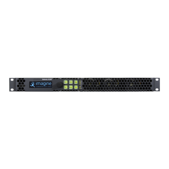
- Page 15 Selenio X100 Installation and Operation Manual Figure 1-1 Front and Rear Views of Selenio X100...
-
Page 16: Environment
Installation and Operation Manual Environment Selenio X100 frames are cooled by forced air drawn in from the front of the frame, and exhausted through vents at the rear of the frame. There must be free passage for air flow on to allow for adequate ventilation, and an ambient temperature of between 32°F to 104°F (0°C to 40°C) with relative humidity of 10% to 90% non-condensing. - Page 17 X100OPT-SK-PD Single-channel program delay software license key only X100OPT-SK-DDPD Dolby Digital Plus Decoder (7.1, 5.1 + 2.0, 2.0 + 2.0) license key for Selenio X100; X100OPT-ADVAUD is required X100OPT-SK-DDPE Dolby Digital Plus Encoder (7.1, 5.1 + 2.0, 2.0 + 2.0) license key for Selenio X100;...
- Page 18 Selenio X100 Installation and Operation Manual Table 1-1 X100 Options and Packages (Continued) Part Numbers Description Software and Hardware Combination Packages X100OPT-ALG-PD-16 Single-channel animated logo generator/inserter and program delay; includes one X100OPT-SK-ALG software key license, one X100OPT-SK-PD software key license...
-
Page 19: Gpi Pinouts
Selenio X100 Installation and Operation Manual GPI Pinouts Key and Slot 12 14 16 18 11 13 15 17 Figure 1-2 Female GPI/Serial Connector Pinouts on Frame Table 1-2 GPI/Serial Pinouts Function GPI Input/Output 0 GPI Input/Output 1 GPI Input/Output 2... -
Page 20: Analog Audio Pinouts
Selenio X100 Installation and Operation Manual Analog Audio Pinouts Ch1a Ch1 b Ch2a Ch2b Ch3a Ch3b Ch4a Ch4 b Figure 1-3 Female Back Panel Analog Audio Input and Output Pinouts on Frame Linear Timecode Pinouts Figure 1-4 Male Back Panel LTC Pinouts... - Page 21 Selenio X100 Installation and Operation Manual Figure 1-5 X100 Signal Flow...
- Page 22 Selenio X100 Installation and Operation Manual...
-
Page 23: Chapter 2 Installation
Environmental Requirements Selenio X100 units are cooled by forced air drawn in from the front, and exhausted through the rear. There must be free passage for air flow at the front and back of each unit to allow for adequate ventilation. - Page 24 Selenio X100 Installation The following items are included: Rear support arms (164-000306Q00) Cable tie bar (164-000305Q00) Brackets (164-100556Q00) Bracket screws (4-40X1/4 PH_Q) Tie bar screws (6-32X3/8 PH) Rack Ears (164-100062Q00) Note: The frame mounting ears and the rack support brackets are reversible. You can install them with the ears at the front and support brackets at the rear, or with the ears at the rear and the support brackets at the front.
- Page 25 13.) Figure 2-4 Attaching the Cable Relief Bar Push the Selenio X100 into the front of the rack, and attach the frame’s front-mounting ears to the rack using the appropriate screws (not provided). Slide the two arms into their slots from the back of the frame and attach the arms to the...
-
Page 26: Selecting An External Balun
The following baluns from http://www.neutrik.com are recommended for the unbalanced-to- balanced AES connections on the Selenio X100. The optional X100OPTCAB-HD-BNC-A (audio) and X100OPTCAB-HD-BNC-V (video) adapter cables are available, if required. NADITBNC-F: Female chassis XLR 110 input to female BNC 75 output ... -
Page 27: Changing Jumper Settings
Selenio X100 Installation and Operation Manual Changing Jumper Settings There are several sets of jumpers on the X100: LTC In/ Out (600 or Hi-Z) Serial Port Rx/Tx Termination (RS-232, RS-422, RS-485) Analog Audio In/Out (600 or Hi-Z) ... - Page 28 Selenio X100 Installation Jumpers set for RS-422 operation Figure 2-7. Serial Port Rx/Tx Termination Analog audio output channel rows Analog audio input channel Figure 2-8. Analog Audio In/Out (600 or Hi-Z)
-
Page 29: Configuring Network Settings
X100 Control Ethernet port and the network hub/switch. Setting IP and Subnet Mask Addresses To allow devices to communicate on a network, you need to set all Selenio X100 devices to the same subnet (network location). When shipped, Selenio X100 units are configured with the same default IP (device identifier) and subnet addresses. - Page 30 Follow this procedure for all remaining Selenio X100 units that require configuration. Connect all Selenio X100 systems and remote panels to a network hub or switch using a 10/100Base-T Ethernet cable. Ensure that all configured Selenio X100 units are detected on the network.
-
Page 31: Changing The Pc Network Settings
In unusual situations, such as correcting a failed software upgrade, you may need to change your PC network settings. Follow these steps to change the settings: Change the IP Address of the PC to match that of the Selenio X100, by following theses steps: Click Start >... - Page 32 In general, the two Subnet Mask and Default Gateway numbers should be identical. The first three octets of the two IP Addresses also are generally identical. For example, if the Selenio X100 has an IP Address of 192.168.248.50, the PC could have an IP Address of 192.168.248.181.
-
Page 33: Remote Control Of The Selenio X100
This section provides the following general configuration procedures: Preparing for Remote Control via Control Panel (on page 16) Selecting a Remote Unit to Control on page 22 Selenio X100 Dual-Channel Video and Audio Processor 3rd Party Hub or Switch Magellan Microsoft Magellan Internet Openview Explorer 6.0... -
Page 34: Preparing For Remote Control Via Control Panel
You can remotely control all Selenio X100 units that share the same subnet. Follow these steps: Ensure all connections and network settings have been made. On the Selenio X100, press the Remote button to bring up a list of available units for control (see Figure 2-12). -
Page 35: Configuring For Web Browser Control
Follow these steps: Connect one end of a crossover or passthrough cable to the Ethernet port on the front of the Selenio X100, and then connect the other end of the cable to a PC with the required software. -
Page 36: Logging In To The Selenio X100 Control Interface
To open a browser connection to an Selenio X100, follow these steps: In your browser, enter the IP address of the Selenio X100, and then click Enter to connect. If the Selenio X100 is in a failed state (i.e., disconnected), then you will see a “browser cannot display the page”... -
Page 37: Accessing Mibs And Configuring Snmp Support
Selenio X100 Installation and Operation Manual Accessing MIBs and Configuring SNMP Support MIB files for the X100 can be downloaded directly from any X100 frame. Before downloading X100 MIBs, you must first download the InfrastructureNetwork.mib file. Copy the following into a browser to access the InfrastructureNetwork.mib: http://<IP address>/InfrastructureNetwork29286.mib... - Page 38 Selenio X100 Installation...
-
Page 39: Chapter 3 Operation
Reset Power cycles the Selenio X100 (this recessed button is located in a hole below and to the right of the LEDs on the front panel; it can be depressed using a paper clip) -
Page 40: Led Functions
Selenio X100 Installation and Operation Manual LED Functions Table 3-2 LED Functions Condition Indicated Name Red: System X100 is powering up Major fault has occurred, such as controller module failure, FPGA failure, or submodule missing Amber: ... - Page 41 Selenio X100 Installation and Operation Manual The outputs include four HD-BNC SDI connectors, two SFPs, one HDMI output, and two analog (composite or SD/HD component) video HD-BNCs (requires optional analog submodule). The following format options are available: Table 3-3 Proc Ch 1 and 2 Out Format Options Follow Ref 1080i/59.94...
-
Page 42: Output Routing
Selenio X100 Installation and Operation Manual Output Routing The Output Routing parameters assign the SDI outputs to their processing channels. The SDI x Out Select parameters control which video channel is assigned to the four SDI outputs. Options are Processing Channel 1 (default) Processing Channel 2, Processing Channel 1 + OSD, and Processing Channel 2 + OSD. - Page 43 Selenio X100 Installation and Operation Manual Channel 1 Channel 2 Tukay The Wonder Dog! ARC-Adjusted 4:3 Program Anamorphic 16:9 Animated Sidebar Content Combined Tukay The Wonder Dog! Program Output with Live I -Wings Sidebar Content Figure 3-2 Creating the Live I-Wings Effect...
- Page 44 56 for details. The Selenio X100 Delays Table (a separate document available on our website) shows the software keys and memory submodule required for each configuration. In addition, the table lists the maximum program delay, and the animated logo duration available per channel, in each configuration.
- Page 45 Mode to Dual Channel. Depending on whether you have one or two X100OPT-SK-PD software keys, the Delay Channel control slide bar is then enabled for each channel. The resolution for the channel delay is displayed in frames; the maximum duration is dependent on the configuration shown in the Selenio X100 Delays Table.
-
Page 46: Local-To-Remote Timing
Selenio X100 Installation and Operation Manual Local-to-Remote Timing In Local-to-Remote Timing, local video is synchronized to incoming decompressed video— which normally has long GOP encoding, and a very long propagation delay resulting from the MPEG encode/decode process. The X100 can overcome these synchronization problems... -
Page 47: Video Sync And Delay
Video Sync and Delay Input Standard Select The Selenio X100 sets the video delay automatically (using the Auto option of the Input Standard Select parameter), or the it can use the standard you set manually as the reference. The following standards are available:... -
Page 48: Actual Video Delay Used
Selenio X100 Installation and Operation Manual Actual Video Delay Used The read-only Actual Video Delay Used parameter reports the actual video delay in frames, based on the cumulative number of frames derived from the delay parameters found in the Video Sync and Delay controls. -
Page 49: Analog Output Control (Video)
Selenio X100 Installation and Operation Manual Note: The Selenio X100 accepts PAL-M composite video that complies to ITU-R BT.470-6 standard (with burst amplitude of 300mV), as well as a variant that is used commonly in Brazil (with burst amplitude of 287mV). Ensure that you select the correct PAL-M standard for detection. -
Page 50: Color Corrector
Selenio X100 Installation and Operation Manual Cmpst Clip Enable (default is No) Cmpst Clip Luma Min (-47.9 mV to 47.9 mV, default is 0.0 mV) Cmpst Clip Luma Max (636.8 mV to 763.1 mV, default is 700.0 mV) ... - Page 51 Selenio X100 Installation and Operation Manual White Slope Normal white knee Increased white knee Decreased white knee Input Figure 3-5 Examples of Increased and Decreased White Slope Black Stretch Normal black knee Increased black knee Decreased black knee Input Figure 3-6 Increased and Decreased Black Knees...
-
Page 52: Gamma Correction
Selenio X100 Installation and Operation Manual Gamma Correction Gamma correction is applied to the RGB as a simple power function, and is applied to each component independently. Gamma Correction 3.00 2.00 0.50 0.30 R, G, and B input Figure 3-7 Example of Gamma Corrections to R, G, and B... -
Page 53: Conversion And Advanced Video Processing
Selenio X100 Installation and Operation Manual Conversion and Advanced Video Processing Aspect ratio conversion is an important part of video format conversion. The X100 supports basic pre-defined arcing controls, custom preset arcing control, code-based automatic arc control, and a highly-configurable ARC code-based table. See page 46 regarding the use of aspect ratio conversion and AFD codes, including graphical representations of ARC and AFD patterns. -
Page 54: Afd-Vi-Wss Insertion
The presence of incoming embedded AFD, VI, and WSS data is shown the Status parameters. AFD, VI and WSS data can be passed from input to output, or it can be generated manually or automatically by the Selenio X100. This function is controlled by the AFD-VI-WSS Insertion options. -
Page 55: Afd-Vi-Wss Custom Mapping
Selenio X100 Installation and Operation Manual AFD/VI/WSS Insert The Pass option allows the incoming AFD code to be inserted unmodified. This option is only supported in SD-ARC and crossconversion modes. In up- or downconversion modes, the Pass option is equivalent to a loss of code, even when an input code is present. When a loss of code occurs, the X100 will insert your selection from the AFD/VI/WSS Pass on Loss parameters. - Page 56 Selenio X100 Installation and Operation Manual Mode Depending on the current input/output video standard setting, the X100 operates in one of four modes: upconversion, crossconversion, downconversion, or SD-ARC. The current operating mode is shown in the ARC Mode Fb parameter in the Status menu.
- Page 57 Selenio X100 Installation and Operation Manual (16:9) 0110-RSVD (16:9) 0111-RSVD (16:9) 1000-16:9 full (16:9) 1001-4:3 p (16:9) 1010-16:9 prtctd (16:9) 1011-14:9 p (16:9) 1100-RSVD (16:9) 1101-4:3 pa 14:9 (16:9) 1110-16:9 a 14:9 ...
-
Page 58: General Information On Arc And Afd
Without AFD, converted video may appear distorted or “cut off” when it appears on different monitors. The Selenio X100 can encode or decode AFD; it can also encode or decode earlier Video Index (VI) and Wide Screen Signaling (WSS) formats. - Page 59 Selenio X100 Installation and Operation Manual Figure 3-9 shows different applications of AFD insertion and decoding. Insertion of AFD (No AFD) Selenio X100 HD/SD-SDI HD/SD-SDI (AFD in VANC) Detection and signaling of ARC HD/SD-SDI ( AFD in VANC ) HD/SD-SDI (AFD in VANC)
-
Page 60: Afd Patterns
Selenio X100 Installation and Operation Manual AFD Patterns In the following pages, Figure 3-11 Figure 3-16 show the different AFD patterns. Comparable WSS and VI templates are included in the SD-SDI Ps. Gray regions indicate areas of the picture Bounding box represents that may be cropped by the receiver the coded frame. - Page 61 Selenio X100 Installation and Operation Manual AFD 4:3 code and description AFD and VI Select Illustration in a parameter options 4:3 coded frame Description WSS name 16:9 Top 16:9 Top Image with a 16:9 aspect ratio as letterbox at the top of a 4:3 coded frame...
- Page 62 Selenio X100 Installation and Operation Manual AFD 16:9 code and description Illustration in a AFD and VI Select Description 16:9 coded frame parameter options WSS name Image with aspect ratio greater than 16:9 >16:9 in 16:9 None as a vertically centered letterbox in a...
- Page 63 Selenio X100 Installation and Operation Manual 4:3 to 16:9 conversion AFD and VI Select Illustration in a Conversion Conversion (Alternative) parameter options 4:3 coded frame WSS name 16:9 Top 16:9 Top 14:9 Top 14:9 Top >16:9 >16:9 in 4:3 Full Frame...
- Page 64 Selenio X100 Installation and Operation Manual 4:3 to 4:3 conversion Conversion AFD and VI Select Illustration in a (Alternative) parameter options 4:3 coded frame Conversion WSS name 16:9 Top 16:9 Top 14:9 Top 14:9 Top >16:9 >16:9 in 4:3 Full Frame...
- Page 65 Selenio X100 Installation and Operation Manual 16:9 to 4:3 conversion Conversion AFD and VI Select Illustration in a Conversion (Alternative) 16:9 coded frame WSS name parameter options >16:9 in 16:9 None AFD Code: 0100 16:9 Full Anamorphic AFD Code: 1000...
- Page 66 Selenio X100 Installation and Operation Manual 16:9 to 16:9 conversion AFD and VI Select Conversion Illustration in a Conversion parameter options 16:9 coded frame (Alternative) WSS name >16:9 in 16:9 None AFD Code: 0100 16:9 Full Anamorphic AFD Code: 1000...
-
Page 67: Scalar Configuration
Selenio X100 Installation and Operation Manual Scalar Configuration These parameters provide a number of controls to optimize your custom ARC settings. Scalar Config Fill Color sets the background color that may appear around the perimeter of a scaled image. Options are: Black (default) ... -
Page 68: Logo Generation And Insertion
Use this parameter to enable cadence detection and “film mode” video processing. Logo Generation and Insertion The Selenio X100 provides logo generation, static on-screen logo insertion, and animated on-screen logo insertion.This feature requires an optional 8 GB or 16 GB memory module (X100OPT-MEMMOD8GB or X100OPT-MEMMOD16GB, respectively);... -
Page 69: Installing And Displaying Logo Files
Selenio X100 Installation and Operation Manual Note: Logos are loaded sequentially. Thus, the 2nd channel logo won't begin loading until the 1st channel logo file and its control are first loaded. Installing and Displaying Logo Files To load a logo file into main board storage, follow Logo x > Select File, and then select Logo Enable >... -
Page 70: Basic Steps To Create Static Logo Files
Step 1: Install LogoCreator Software All logos used by the X100 must either be generated as .mg2 files, or converted to that format. LogoCreator software is contained in the Icon application, found in the Imagine Communications Manuals and Product Resources DVD. -
Page 71: Step 2: Convert Files To The .Mg2 Format
Selenio X100 Installation and Operation Manual If a version of LogoCreator already exists on the PC, ensure that you first uninstall the program and restart the computer. Then proceed with the steps below: Close all other software applications running on the PC and then insert the IconTools CD-ROM into the computer's CD-ROM tray. -
Page 72: Video Tsg-Osd 1 And 2
The Logo Position and Opacity controls on the LogoCreator software are not active. These features are controlled by the X Position, Y Position, and Transparency parameters found in the Selenio X100 parameter list at Video > Processing Channel 1 and 2 > Logo 1 and 2 > Raster x. -
Page 73: On Screen Display (Osd)
During firmware upgrades, the test signal generator automatically outputs color bars. On Screen Display (OSD) The Selenio X100 has the capability to provide an output with or without on-screen display (OSD). Currently, both the timecode and the source ID can be displayed using the Stream x Time Code Enable and Stream x Source ID Enable parameters. -
Page 74: Data Output And Data Bridging
Selenio X100 Installation and Operation Manual Data Output and Data Bridging For each SDI output blanking line, you can select up to two kinds of data to be embedded into the same line. Source data can be routed from the same processing channel input or bridged from a different processing channel input. -
Page 75: Scte-104
Selenio X100 Installation and Operation Manual At this time, Bar Data and Pan-Scan for VI and AFD are not supported in data embedding and de-embedding. The X100 supports closed captioning, Teletext (OP-47), and timecode. Other ancillary data will be stripped from the output stream, except when the X100 is in frame sync mode. - Page 76 Selenio X100 Installation and Operation Manual The X100 can also create SCTE-104 VANC packets when it detects an RS-232/RS-422/ RS-485 serial input data containing SCTE-104 multiple operation messages with splice request messages or DTMF descriptor request messages. The VANC packet is inserted into the video on the next available video field after the message is extracted from the serial input data.
- Page 77 Video Input 1 Data De-Embedder 1 Operation Message containing splice request and DTMF Message descriptor request Decoder Outputs 1-8 SCTE-104 VANC Video Input 2 Data De-Embedder 2 SCTE-104 SCTE-104 Trigger Mode Extraction Proc Channel Figure 3-19 Selenio X100 SCTE-104 Data Processing Flow...
-
Page 78: Scte-104 Insertion And Extraction Setup Examples
Selenio X100 Installation and Operation Manual SCTE-104 Insertion and Extraction Setup Examples Inserting SCTE-104 Packets on Line 10 Using GPI Triggers Follow these steps to insert SCTE-104 packets using GPI triggers: First configure each GPI input to Rising Edge for SCTE-104 triggers: At GPI and Rules Engine >... - Page 79 Selenio X100 Installation and Operation Manual Extracting SCTE-104 Data Packets to Trigger GPO Outputs (Static Mode) Configure each GPIO output port for SCTE-104 triggers. At GPI and Rules Engine > GPI > GPI Direction, set all eight GPIO Direction to Output options.
- Page 80 Selenio X100 Installation and Operation Manual At GPI and Rules Engine > GPI > GPI Output, select GPI Output to Edit > GPIO 0, and Event > SCTE104/BT1685 Control. At GPI and Rules Engine > GPI > GPI Output > GPI Data Type, select SCTE-104 for GPO Data Type.
-
Page 81: Bt-1685
Selenio X100 Installation and Operation Manual BT-1685 Overview The X100 uses VANC data packets for the transmission of Inter-Station control data, according to the ITU-R BT.1685 standard. The BT-1685 data packet contains the following structure: SDID Ancillary Data Data Identification... - Page 82 Selenio X100 Installation and Operation Manual Table 3-8 Inter-Station Control Data Format Trigger Counter Trigger Countdown Status Bits Words Word Number 34 108- The X100 only uses word number 30 for the transmission of the eight GPI trigger bits. When a trigger condition is detected, the corresponding trigger bit (Q1-Q8) is set high;...
-
Page 83: Afd, Vi And Wss
Selenio X100 Installation and Operation Manual ii. Trigger to the desired value (options are RisingEdge, FallingEdge, ActiveHigh and ActiveLow) Configure the BT-1685 inserter to insert BT-1685 packets on line 12 of video output 1: Go to Video > Video Output and Routing > Proc Ch 1 Out Format and then select 1080i/59.94. -
Page 84: Arib
Selenio X100 Installation and Operation Manual ARIB The X100 reports the current audio mode embedded in the incoming ARIB packet, and has the ability to replace the field with a different value. Closed Captioning/Teletext To make changes to the closed captioning and Teletext settings, select the following parameters located at Data Output >... -
Page 85: Timecode
RP196 LTC in HANC The Selenio X100 supports ancillary timecode insertion to video output, extraction from video input, LTC timecode generation and extraction, and conversion between all of the above supported timecode formats and frame rates. To support timecode frame rate conversion, local timecode generators for the LTC and each of the video processing channels ensure that the generated timecode is always in sequence according to the selected output format. -
Page 86: Audio Embedding
To enable all output timecode manually and immediately, set Immediate Jam Sync to Yes. You can also set up the Selenio X100 to jam sync the output time to the input time daily at a specific time. To do this, set Data > Advanced Status and Control > Timecode >... -
Page 87: Passing Embedded Non-Pcm Audio Through The Frame Sync
Ch 1 Out Format (Video Output and Routing > Output Format) to Proc Bypass. Audio Embedding Control The Selenio X100 makes it possible to embed audio on a pair-by-pair basis. Each embedder has four groups, with two pairs in each group. Using the EMB x Grp x Pair x embed control parameters, you can embed a single pair of audio at any one time. - Page 88 Append Embedding When you select Append embedding, the Selenio X100 attempt to insert the audio data and control packets immediately following the last existing data/control packet in the horizontal ancillary data space (ADS). Append embedding is only valid if the audio group to be embedded does not already exist.
- Page 89 Selenio X100 Installation and Operation Manual ADS before embedding Pre existing Group ADS after attempting to embed group 1 Pre-existing Group Result: Error is returned Figure 3-23 Append Embedding Mode; Adding Group 1 When Group 1 Already Exists If you insert Group 2 audio when there is pre-existing Group 1 audio in the ancillary data...
- Page 90 Selenio X100 Installation and Operation Manual Overwrite Embedding When you select Overwrite embedding, the X100 attempts to overwrite any existing audio data and control packets of the same group number with the new audio data. This setting is valid only if the audio group to be embedded already exists. If the new sample distribution does not exactly match the existing audio data packet sample distribution, the embedder marks some audio data packets for deletion (DID word is set to 180h).
-
Page 91: Embedding Errors
Selenio X100 Installation and Operation Manual Audio Embedding Errors Table 3-10 Audio Embedding Error Descriptions Error Description Group (1–4) This error occurs if the embedder is set to Append mode for a particular Append audio group, but that audio group already exists in the incoming SDI Embedding signal. -
Page 92: Preventing Embedding Errors
Selenio X100 Installation and Operation Manual Preventing Embedding Errors To avoid embedding errors, follow these guidelines: Set the embedding mode to Auto. If the group is present, it will be overwritten; if it is not present, it will be appended. The overwrite and append errors are warnings that the desired operation is not being performed. -
Page 93: Audio I/O (Input/Output) Assignment
HDMI Out Pair 1 1000 Hz Tone HDMI Out Pair 4 2000 Hz Tone . . . AAP 1 4000 Hz Tone 1000 Hz Tone (-18dBFS) AAP 4 1000 Hz Tone (-20dBFS) (32 channels) Mute Figure 3-30 Selenio X100 Audio Routing... -
Page 94: Audio Inputs And Outputs
Audio Inputs and Outputs Inputs Selenio X100 supports embedded-audio input, AES audio input, and analog audio input. In addition, the X100 processes embedded audio from the SDI video input in SD, HD, or 3G (Level A and Level B-DL) formats, and include two independent audio de-embedders—each supporting sixteen mono channels. -
Page 95: Audio Input Delay And Sync
Dolby, DTS Neural, and DTS Neural Surround options. Synchronization Parameters The Selenio X100 performs sample rate conversion on all audio input channel pairs. Streams carrying compressed audio automatically bypass the SRC block. The Sample Rate Conversion menus (Audio Input Delay and Sync > xxxSample Rate Conversion) make it possible for you to manually bypass SRCs on a per-pair basis in situations where legacy equipment provides unreliable compressed audio signals. -
Page 96: Audio Output Routing And Delay
Selenio X100 Installation and Operation Manual Audio Control Style (Mono or Stereo) Audio V-Fade (clean audio hotswitch) Audio LOV Output Mode (Pass or Mute) Fade Time (0 to 10 seconds in increment of 1ms) V-Fade Mute Time (0 to 1 second in increment of 1ms) ... - Page 97 Selenio X100 Installation and Operation Manual AES destinations can match delay from either processing channel, provided its native routing delay doesn’t already exceed the delay in the associated processing channel. In Figure 3-33, if AAP 1 Delay is greater than AAP2 Delay, AES alignment with Processing Channel x is possible.
-
Page 98: Audio Bit Manipulation
Installation and Operation Manual Audio Bit Manipulation This section contains information on the manipulation of bits that occur when using the Selenio X100 modules. RX Key: N = not recognized, Y = recognized, S = recognized and stored or passed through or both... - Page 99 Selenio X100 Installation and Operation Manual Table 3-11 C-Bit Manipulation (Continued) Byte Function Remarks 6 to 7 Reserved Set to [0] 0 to 7 Reserved Set to [0] 0 to 1 [00] Not a reference Set to [00] [01] Grade 1 reference...
-
Page 100: Audio Metadata
-20 dBFs GPI and Rules Engine The Selenio X100 provides eight GPI pins for automation, with configurable input or output directions. The GPIs are open collector style, with approximately 10 K pull-ups to +5V. In other words, you can use contact closure-to-ground switches to control these GPI inputs. -
Page 101: Rules Engine
Selenio X100 Installation and Operation Manual Each GPI pin can be individually set to either input or output status; thus there are eight controls in total (parameters GPI 0 Direction to GPI 7 Direction), located at GPI and Rules Engine > GPI > GPI Direction. -
Page 102: Custom Gpi Output Script
Selenio X100 Installation and Operation Manual <statement> ::= IF <condition> THEN <assignment> { <assignment> } <condition> ::= <comparison> { <logic op> <comparison> } <comparison> ::= GPIx <comparison op> y Where x is in the range of [0, 7], y could be 0 or 1 <assignment>... -
Page 103: Parameter Control Script
Selenio X100 Installation and Operation Manual “Integer: y is integer value of the parameter “Enum: y is the enum value index inside the enum “String: y is in a 'zzzz' string format, where z is a character. Special character can be used as wild card. -
Page 104: Green-Power Save
Selenio X100 Installation and Operation Manual Read-only Script Status reports the parsing and active status of the script. If a syntax error is detected when a new script is entered, this parameter will report Error: x message (x is an index number starting from the beginning of the script to indicate around which character the script parser first encounters a syntax error). -
Page 105: Genlock
Installation and Operation Manual Genlock The Selenio X100 can lock to an external reference input that can be either tri-level sync (1080i/1080p/720p) or bi-level sync (NTSC/PAL-B/PAL-M color black or black burst). A digital audio reference (DARS) signal that is compliant to the AES-11 standard can also be applied. -
Page 106: Video Output
Selenio X100 Installation and Operation Manual Note: Line Sync for dual link video formats is not supported at this time. For the Line Sync mode to operate, the reference frame rate must be identical to the video frame rate. Line Sync does not support V-phase (line) and frame delay. -
Page 107: Selenio X100
SavedPreset0xx. SFP+HDMI+OUT Operation In addition to the built-in HDMI output at the back of the frame, the Selenio X100 also supports HDMI output using the optional SFP+HDMI+OUT SFP module. Proper setup is required to make this SFP function correctly. - Page 108 Selenio X100 Installation and Operation Manual Table 3-14 Output Speaker Mapping (Continued) Speaker Mapping Audio Channel Number* Number * FL = Front Left, FC = Front Centre, FR = Front Right, FLC = Front Left Centre, FRC = Front Right Centre, RL = Rear Left, RC = Rear Centre,...
-
Page 109: Chapter 4 Advanced Audio Processing
Advanced Audio Processing Software Key License Credits Overview To use the Advanced Audio Processing option, you will need to purchase the X100OPT-ADVAUD audio submodule, and a number of X100OPT-SK-DTS or X100OPT-SK-DDD, or X100OPT-SK-DDE Software Key License Credits. The number of license credits that you need depends on which audio functions you select for DTS Neural, Dolby Digital (AC-3) Decoder, Dolby Digital (AC-3) Encoder, Dolby E Decoder, or Dolby E Encoder. -
Page 110: Enabling Dts Neural And Dolby Modes
Selenio X100 Installation and Operation Manual Enabling DTS Neural and Dolby Modes Follow these steps to enable the DTS Neural and Dolby Modes: Consult Table 4-1, and then select either select Normal or Minimum at Misc > Other > AAP Latency Mode. - Page 111 Selenio X100 Installation and Operation Manual Table 4-1. Advanced Audio Processing Modes, Latency, MCPS, and Credit Cost (Continued) MCPS, Minimal Mode Normal Latency Normal Credit Cost Latency Latency *(%) M12: MultiMerge, Loudness Control 112.2 ms (low) / 133.53 74.86 ms (low) /...
-
Page 112: Dolby Products
Selenio X100 Installation and Operation Manual Dolby Products Figure 4-1 Figure 4-2 show how Dolby is used in typical Selenio X100 applications. Dolby Digital and Dolby Digital Plus Encoder Dolby Digital Dolby Digital Plus Encode Optional 5.1 RTLL DD 2.0 5.1 to 7.1... -
Page 113: Dolby-E Alignment
This is commonly known as the guard band. On the Selenio X100, the Dolby-E alignment timing is determined by the value of the SDI 1 or SDI 2 Dolby E Start Line embedder controls in EMB x >Controls. -
Page 114: Aap Internal Metadata
(default is Processing Ch 1 Output). Dolby Audio Metadata When you apply external metadata to the Selenio X100, the metadata properties persist even after you remove the external metadata from the module. Performing a Factory Default of the user settings does not clear the metadata properties that were received when external metadata was present. - Page 115 Selenio X100 Installation and Operation Manual Table 4-2. Decoder Behavior Mode Input #1 Input #2 Output Notes [M7] Decoder MUTE PCM #1 DEC #2 PCM #1 DEC #1 MUTE DEC #? Undetermined: one of the streams gets decoded DEC #1...
- Page 116 Selenio X100 Installation and Operation Manual Table 4-2. Decoder Behavior (Continued) Mode Input #1 Input #2 Output Notes [M9] DD/DE Decoder PCM #1 DEC #2 DEC #2 DEC #1 DEC #1 DEC #? Undetermined: one of the streams gets decoded...
- Page 117 Selenio X100 Installation and Operation Manual DTS Neural Products The block diagrams shown in Figure 4-3 Figure 4-5 illustrate the uses of the different DTS Neural Software Key License Credits. UpMix L , R L , R or Upmix Lt , Rt or 2.
- Page 118 Selenio X100 Installation and Operation Manual Loudness Control 4 X 2.0 L , R or L , R or Loudness Lt , Rt or Lt , Rt or measurement 2. 0 output 2. 0 input Lo , Ro or Lo , Ro or...
- Page 119 Selenio X100 Installation and Operation Manual UpMix + Loudness Control L, R L, R or Loudness Upmix Lt , Rt or measurement 2. 0 input 5. 1 output C , LFE processing Lo , Ro or and control Lw, Rw...
-
Page 120: Dts Neural Surround Audio Upmix
Selenio X100 Installation and Operation Manual DTS Neural Surround Audio UpMix Overview The DTS Neural Surround UpMix renders any two channel audio source (stereo, matrix encoded stereo, LtRt, or DTS Neural Surround LwRw) as surround sound. The DTS Neural Surround UpMix can simultaneously position individual elements within the surround field, creating high levels of image stability and granularity. -
Page 121: Audio Delay
Selenio X100 Installation and Operation Manual Audio Delay Table 4-4. DTS Neural Surround Audio UpMix Parameters Parameter Name Function Options Uninitialized UpMix Status Indicates the state of the AAP mode Running Not Running (bypassed) Not Running ... -
Page 122: Dts Neural Surround Audio Downmix
Selenio X100 Installation and Operation Manual DTS Neural Surround Audio DownMix Overview The DTS Neural Surround DownMix enables 5.1 surround sound to be transported through any stereo infrastructure. The DownMix process is based upon the principle that both natural stereo and 5.1 content are two-dimensional; both contain width and depth spatial attributes. - Page 123 Selenio X100 Installation and Operation Manual Table 4-5. DTS Neural Surround Audio DownMix Parameters 0 Hz LFE Cutoff Specifies the low-pass cutoff frequency of the LFE channel (0 specifies no LFE channel) 60 Hz 80 Hz 100 Hz ...
-
Page 124: Dts Neural Surround Audio Multimerge
Selenio X100 Installation and Operation Manual DTS Neural Surround Audio MultiMerge Overview The DTS Neural Surround MultiMerge enables broadcasters to transition from stereo to 5.1 surround sound, providing viewers with a 24/7 surround sound experience. With MultiMerge in line, 5.1 original content is passed unaffected to the viewer while original stereo content is UpMixed to a 5.1 surround sound image. - Page 125 Selenio X100 Installation and Operation Manual Table 4-6. DTS Neural Surround Audio MultiMerge Parameters Parameter Name Function Options Uninitialized MultiMerge Status Indicates the state of the AAP mode Running Not Running (bypassed) Not Running Input Selection Mode Specifies how input channels are selected.
- Page 126 Selenio X100 Installation and Operation Manual Table 4-6. DTS Neural Surround Audio MultiMerge Parameters (Continued) Phantom Center Downmix L/R Encoding Specifies the encoding mode for the left and right Mode channels Hard Center 0 Hz Downmix LFE Cutoff...
- Page 127 Selenio X100 Installation and Operation Manual Table 4-7. Input Selection Mode Option Descriptions (Continued) Option Notes Stereo Detect If audio is present on the L/R pair of the 5.1 input, the Aux input is overridden. Information on the C/LFE and Ls/Rs pairs of the 5.1 input is ignored.
-
Page 128: Dts Neural Loudness Control
DTS Neural Loudness Control Overview The Selenio X100 offers four channels of DTS Neural Loudness Control—a loudness leveling device that uses advanced psycho-acoustic and signal processing techniques to accurately detect and regulate the perceived loudness of stereo and 5.1 sources. Using this feature, you can regulate audio without creating the perception of being “squished”... - Page 129 Selenio X100 Installation and Operation Manual Presets The Loudness Control feature uses four different presets (Ultra-Light, Light, Medium, and Aggressive). Table 4-8 lists the values that each of these presets represents. Table 4-8. DTS Neural Loudness Control Preset Settings Parameter Name...
- Page 130 Selenio X100 Installation and Operation Manual Loudness Control Mapping Each Loudness Control menu within each AAP block (DTS Neural Loudness Ctrl 1/2/3/4) corresponds to a loudness control function of a given AAP loudness control mode. Each mode containing LC may have one or more loudness control sections with related control parameter menus.
- Page 131 Selenio X100 Installation and Operation Manual Loudness Control Parameters Table 4-10. DTS Neural Audio Loudness Control Parameters Parameter Name Function Options Enable Loudness Control Function Enables the Loudness Control feature Disable Uninitialized Loudness Control Status Indicates the state of the AAP mode Running ...
- Page 132 Selenio X100 Installation and Operation Manual Table 4-11 Recommended Loudness Control Presets, by Country Target Loudness Allowable Country Recommendation Suggested Preset Variance Australia and OP-59 Unknown at Dependent on Allowable New Zealand this time Variance Canada ATSC A-85 +/- 2...
-
Page 133: Chapter 5 Specifications
Specifications Video Input 3G/HD/SD-SDI Video Input Table 5-1 SDI Input Specifications Item Specification Number of Inputs 3G: SMPTE 424M, SMPTE 425 Level A, Level B-DL (YCrCb, 4:2:2, 10-bit with Standard 16 channels of embedded audio; 2.97, 2.97/1.001 Gb/s) HD: SMPTE 292M (1.485, 1.485/1.001 Gb/s) ... -
Page 134: Component Video Input
Selenio X100 Installation and Operation Manual Component Video Input Table 5-2 Component Video Input Specifications Item Specification 525, 625 Format 720p/60, 720p/59.94, 720p/50 1080i/60, 1080i/59.94, 1080i/50, 1080sf/30, 1080sf/ 29.97, 1080sf/25,1080sf/24, 1080sf/23.98 1080p/30, 1080p/29.97, 1080p/25, 1080p/24, 1080p/ ... -
Page 135: Audio Input
Selenio X100 Installation and Operation Manual Audio Input Analog Audio Input Table 5-4 Analog Audio Input Specifications Item Specification Number of Inputs 8 mono channels Type Balanced Connector DB-25, Tascam-style cable snake for balanced 8-channel audio Input Audio Level 28 dBu to 12 dBu (adjustable in 0.5 dB increments) Input Impedance High-Impedance or 600, jumper selectable... -
Page 136: Unbalanced Aes Input
Selenio X100 Installation and Operation Manual Unbalanced AES Input Table 5-6 Unbalanced AES Input Item Published Specification Number of Inputs 16 (shared with AES outputs, software configurable) Connector HD-BNC Impedance 75 Return Loss >25 dB, 0.1 to 6.0 MHz Sensitivity <100 mV... -
Page 137: Video Output
Selenio X100 Installation and Operation Manual Video Output 3G/HD/SD-SDI Output Table 5-7 3G/HD/SD-SDI Output Video Specifications Item Specification Number of Outputs 3G: SMPTE 424M, SMPTE 425 Level A, Level B-DL (YCrCb, Standard 4:2:2, 10-bit with 16 channels of embedded audio; 2.97, 2.97/1.001 Gb/s) -
Page 138: Component Video Output
Selenio X100 Installation and Operation Manual Component Video Output Table 5-8 Component Video Specifications Item Specification 525, 625 Format 720p/60, 720p/59.94, 720p/50 1080i/60, 1080i/59.94, 1080i/50, 1080sf/30, 1080sf/ 29.97, 1080sf/25,1080sf/24, 1080sf/23.98 1080p/30, 1080p/29.97, 1080p/25, 1080p/24, 1080p/ 23.98 HD-BNC ... -
Page 139: Hdmi Output
Selenio X100 Installation and Operation Manual HDMI Output Table 5-10 HDMI Output Specifications Item Specification Number of outputs 1080p/60, 1080p/59.94, 1080p/50, 1080p/24, 1080p/ Standards 23.98 1080i/60, 1080i/59.94, 1080i/50, 1080psf/24, 1080psf/ 23.98 720p/60, 720p/59.94, 720p/50 525, 625 ... -
Page 140: Audio Output
Selenio X100 Installation and Operation Manual Audio Output Analog Audio Output Specifications Table 5-11 Analog Audio Output Specifications Item Specification Number of Outputs 8 mono channels Type Balanced Connector DB-25, Tascam-style cable snake for balanced 8-channel audio Output Audio Level 28 dBu to 12 dBu (adjustable in 0.5 dB increments) -
Page 141: Unbalanced Aes Output
Selenio X100 Installation and Operation Manual Unbalanced AES Output Table 5-13 Unbalanced AES Output Specifications Item Published Specification Number of outputs 16 (shared with AES inputs, software configurable) Standard AES 3, SMPTE 276M Type Unbalanced, AC coupled Connector HD-BNC Impedance 75... -
Page 142: Sfp Specifications, Input
Selenio X100 Installation and Operation Manual SFP Specifications, Input SDI Electrical Dual Receiver Table 5-14 SFP+2ERX+NR Specifications Item Specification Connector Type HD-BNC 3G: SMPTE 424M (2.97, 2.97/1.001 Gb/s) Standards HD: SMPTE 292M (1.485, 1.485/1.001 Gb/s) SD: SMPTE 259M-C (270Mb/s, 525/625 component video) ... -
Page 143: Sdi Optical Dual Receiver
Selenio X100 Installation and Operation Manual SDI Optical Dual Receiver Table 5-16 OP+SFP+RR Dual Input Fiber Specifications Item Minimum Typical Maximum Notes Number of LC Input Connectors 2 X 2 3G: SMPTE 424M Standards HD-SDI: SMPTE 292M SD-SDI: SMPTE 259M ... -
Page 144: Sfp Specifications, Output
Selenio X100 Installation and Operation Manual SFP Specifications, Output SDI Electrical Dual Transmitter Table 5-17 SFP+2ETX+NR Specifications Item Specification Connector Type HD-BNC 3G: SMPTE 424M (2.97, 2.97/1.001 Gb/s) Standards HD: SMPTE 292M (1.485, 1.485/1.001 Gb/s) SD: SMPTE 259M-C (270Mb/s, 525/625 component ... -
Page 145: Sdi Electrical Dual Transmitter With Reclocker
Selenio X100 Installation and Operation Manual SDI Electrical Dual Transmitter with Reclocker Table 5-18 SFP+2ETX Specifications Item Specification Connector Type HD-BNC 3G: SMPTE 424M (2.97, 2.97/1.001 Gb/s) Standards HD: SMPTE 292M (1.485, 1.485/1.001 Gb/s) SD: SMPTE 259M-C (270Mb/s, 525/625 component ... -
Page 146: Sdi Electrical-To-Hdmi Converter
Selenio X100 Installation and Operation Manual Table 5-19 SFP+DVI+OUT Specifications Item Specification TMDS Rise/Fall Time Typical: 175 ps (Min: 75 ps) Maximum Output Current Min: 55 mA (5V) Output Voltage (5V) Typical: 5.05V (4.8 to 5.3 V) Power Consumption Typical: 1030 mW... -
Page 147: Sdi Optical Dual Transmitters
Selenio X100 Installation and Operation Manual SDI Optical Dual Transmitters Table 5-21 OP+SFP+TT+xx+yy* Dual Output Transmitter Specifications Item Minimum Typical Maximum Notes Number of LC Connector Outputs SD: SMPTE 259M, C Standards HD: SMPTE 292M 3G: SMPTE 424M ... - Page 148 Selenio X100 Installation and Operation Manual Table 5-22 OP+SFP+TT+1313 Specifications Item Minimum Typical Maximum Notes Number of LC Connector Outputs 3G: SMPTE 424M Standards HD: SMPTE 292M SD: SMPTE 259M ° Peak Wavelength 1280 nm 1310 nm...
-
Page 149: Miscellaneous
Selenio X100 Installation and Operation Manual Miscellaneous DARS Input Table 5-23 DARS Input Specifications Item Specification Standard AES3, SMPTE 276M Type Unbalanced, AC-coupled Connector HD-BNC Sensitivity 100 mV Impedance 75 Return Loss >25 dB, 0.1 MHz to 6 MHz Sampling Rate... -
Page 150: Genlock
Selenio X100 Installation and Operation Manual Genlock Table 5-26 Genlock Specifications Item Published Specification Connector HD-BNC Impedance 75 Return Loss >40 dB 25 Hz to 10 MHz (SMPTE 318M-1999) NTSC/PAL-B/PAL-M: 1V pk-to-pk, -6.0dB to +6.0dB Input Level Tri-Level Sync: 600mV pk-to-pk, -6.0dB to +6.0dB ... -
Page 151: Ltc Output
Note: Shielded twisted pair cables should be used for LTC input and LTC output Power Consumption The Selenio X100 provides redundant power; during normal operation, both power supplies are on. However, only one is powering the frame at any time. The line voltage is auto-detected. -
Page 152: Rs-232/422/485 Specifications
20-Pin Header Connector 115200bps (Audio Metadata) Output Baud Rate 9600, 19200, 38400, 57600, 115200bps (SCTE-104) Temperature The operating temperature of the Selenio X100 is 32°F to 104°F (0°C to 40°C) with relative humidity of 10% to 90% non-condensing. -
Page 153: Appendix A Laser Safety Guidelines
Laser Safety Guidelines Laser Safety for Fiber Optic Back Modules WARNING! Use of controls, adjustments, and procedures other than those specified in this document may result in hazardous laser radiation exposure. Optical fiber telecommunication systems use semiconductor laser transmitters that emit infrared light that is normally not visible to the human eye. -
Page 154: Precautions For Unenclosed Systems
Appendix A Laser Safety Guidelines Precautions for Unenclosed Systems During service, maintenance, or restoration, an optical fiber telecommunication system is considered unenclosed. Under these conditions, follow the practices described below. CAUTION! Only authorized, trained personnel shall be permitted to do service, maintenance, and restoration. -
Page 155: Important Points
Selenio X100 Installation and Operation Manual Table A-1 Typical Contaminants (Continued) Contaminant Comments Frequently caused by touching Film residues Can accumulate from vapors or smoke Powdery coatings Can be left behind after water or other solvents evaporate Important Points Before you begin cleaning, always inspect the fiber connections. -
Page 156: Inspection And Cleaning Procedure
Appendix A Laser Safety Guidelines Inspection and Cleaning Procedure Inspection To inspect and clean the fibers, follow these steps: Ensure the fiber is not “live.” WARNING! Eye damage may occur if an optical instrument such as a microscope, magnifying glass, or eye loupe is used to stare at an energized fiber end. Inspect the fiber endface with a fiberscope. - Page 157 Selenio X100 Installation and Operation Manual If the contamination persists, repeat the dry and wet cleaning procedure until the endface is clean. If the fiber end still remains dirty after repeated cleaning attempts, call Customer Service for further instructions; if the fiber end is clean, return to the installation...
- Page 158 Appendix A Laser Safety Guidelines...
-
Page 159: Appendix B Servicing
Servicing Overview User-serviceable replacement parts are available for the following Selenio X100 components: Fan (131-100021000) Power supply (X100-PSU-200W) OLED display/button board, complete assembly with OLED display, selection buttons and rotary control shaft encoder (170-100689Q00) Rotary control shaft encoder (X50SPR-SE) ... -
Page 160: Cover Removal And Replacement
Appendix B Servicing Cover Removal and Replacement The X100 features a separate top cover and front panel control assembly. Follow the steps listed below: Top Cover Disconnect both AC power cords. WARNING: You can receive an electric shock from exposed parts of the power supplies. -
Page 161: Front Panel Control Assembly
Selenio X100 Installation and Operation Manual Front Panel Control Assembly For fan replacement or control panel servicing, continue with the following steps to remove the front cover. Remove the 9 screws from the front cover (including top and bottom), but do not remove... - Page 162 Appendix B Servicing If necessary, detach the ribbon cable connector from the front panel control assembly by pushing apart the two side clamps. and then wiggling the connector apart (Figure B-5). CAUTION: Do not pull on the actual ribbon cable. This may result in damage to the connector and or the ribbon cable itself.
-
Page 163: Fan Module Replacement (131-100021000)
Selenio X100 Installation and Operation Manual Fan Module Replacement (131-100021000) Each front fan module (part number 131-100021000) is individually mounted and connected. The wiring connector to each fan enters from its top right corner (when viewing the fans from inside the frame). The number 2 fan is aligned differently: the wires enter at the bottom left corner. -
Page 164: Power Supply Replacement (X100-Psu-200W)
Appendix B Servicing Power Supply Replacement (X100-PSU-200W) The X100 includes two power supplies. In the event of a power supply failure, follow these steps to remove and replace the unit: Remove the top cover, as described on page 148, ensuring both AC power cords are unplugged. -
Page 165: Installation Of Advanced Audio Processing Submodule (X100Opt-Advaud)
Installation and Operation Manual Installation of Advanced Audio Processing Submodule (X100OPT-ADVAUD) To use advanced audio processing in the Selenio X100, you must install an X100OPT-ADVAUD audio submodule and purchase the appropriate software license keys. Follow these steps to install the audio submodule: Remove the top cover, as described on page 148, ensuring both AC power cords are unplugged. -
Page 166: Oled Display/Button Board Replacement (170-100689Q00)
Appendix B Servicing OLED Display/Button Board Replacement (170-100689Q00) Follow these steps to remove and replace an OLED display: Remove front panel control assembly as described on page 149, ensuring both AC power cords are disconnected. Slide the rotary control knob straight off its shaft (Figure B-11). - Page 167 Selenio X100 Installation and Operation Manual Slide circuit board out. Figure B-13. Removing Circuit Board Discard the original circuit board, and then reverse steps 1 to 5 to re-install the new unit. Reverse the steps found in Cover Removal and Replacement...
-
Page 168: Rotary Control Shaft Encoder Replacement (X50Spr-Se)
Appendix B Servicing Rotary Control Shaft Encoder Replacement (X50SPR-SE) There are two possible replacement parts for a broken shaft encoder: Rotary control shaft encoder unit (X50SPR-SE) that must be soldered to the front circuit board Complete OLED display circuit board unit (170-100689Q00). ... - Page 169 Selenio X100 Installation and Operation Manual Figure B-15. Rotary Control Shaft Encoder Removed Insert the new replacement rotary control shaft encoder from the front (Figure B-16). Figure B-16. Inserting New Rotary Control Shaft Encoder...
- Page 170 Appendix B Servicing Solder the connections to the back of the circuit board, ensuring the rotary control shaft encoder is flush with the circuit board (Figure B-17). Figure B-17. New Rotary Control Shaft Encoder Installed Gently press the circuit board back into place, taking care not to bend the pins on the left side.
-
Page 171: Analog Video Input/Output Module (X100Opt-Avio)
Selenio X100 Installation and Operation Manual Analog Video Input/Output Module (X100OPT-AVIO) Follow these steps to install the optional analog video input/output module: Remove the top cover, as described on page 132, ensuring both AC power cords are disconnected. Remove and set aside the two screws from the rear cover plate (Figure B-18). - Page 172 Appendix B Servicing From the inside of the X100 chassis, angle the connector end of the analog video submodule through the rear panel cutout and then align the multipin connector with its mate on the main board (Figure B-20). Angle connectors through rear cutout.
- Page 173 Selenio X100 Installation and Operation Manual Figure B-22. Replacement of Cover Plate Replace the twelve HD-BNC nuts back onto the cover plate using the HD-BNC Nut Tool (Figure B-23). Finger-tighten each HD-BNC nut until it contacts the metal plate. Align the two prongs of the tool with the two notches on the HD-BNC nut.
-
Page 174: Animated Logo Generator/Inserter And Program Delay Submodule
Appendix B Servicing Animated Logo Generator/Inserter and Program Delay Submodule Follow these steps to install the X100OPT-MEMMOD8GB or X100OPT-MEMMOD16GB memory submodule, required for the animated logo and program delay options: Remove the top cover, as described on page 148, ensuring both AC power cords are unplugged. -
Page 175: Index
Index Symbols 3D Comb Decoding 36 Backlight of display 27 Baluns 14 – Black knee 38 Block diagrams – Active Format Description (AFD) 41 audio and video 9 Administrator user 24 – Dolby and DTS Neural 100 Adobe After- Effects software 57 –... - Page 176 Selenio X100 Installation and Operation Manual – Dolby Digital and Dolby E 83 Ipconfig command 20 Dry cleaning fiber connections 144 – – DTS Neural 97 – block diagrams 105 – Jumpers 15 – loudness control 116 – Surround DownMix 110 –...
- Page 177 Selenio X100 Installation and Operation Manual – Parameters SFP modules 4 ADS Clean 79 Shipping information x Frame Delay 35 Signal flow 9 Timecode 73 Silverlight 23 Passthrough in DTS Neural Surround 113 Siting requirements 4 Password, default 24 SMPTE 334M VANC standard 72 –...
Need help?
Do you have a question about the Selenio X100 and is the answer not in the manual?
Questions and answers