Table of Contents
Advertisement
Advertisement
Table of Contents

Related Manuals for Imagine Versio


Summary of Contents for Imagine Versio
- Page 1 Versio Edition E...
-
Page 2: Contact Information
English without the written consent of Imagine Communications. All others uses are illegal. This publication is designed to assist in the use of the product as it exists on the date of publication of this manual, and may not reflect the product at the current time or an unknown time in the future. -
Page 3: Table Of Contents
SAS3/SATA LEDs ............19 © 2015 Imagine Communications... - Page 4 Broadcast I/O ..............22 Automation Port and Channel Assignments for Versio ......23 Power Supply Modules .
- Page 5 Anti-Virus Software ............58 © 2015 Imagine Communications...
- Page 6 Versio System Specifications ........
- Page 7 Preface...
-
Page 8: Preface
Manual Information Purpose This manual details the features, installation, operation, maintenance, and specifications of your Versio system. Audience This manual is written for engineers, technicians, and operators responsible for the system installation and setup. Writing This manual adheres to the following writing conventions. -
Page 9: Unpacking/Shipping Information
Your system has been carefully inspected, tested, and calibrated prior to shipment to ensure years of stable and trouble free service. Before you install and configure your Versio system, follow these steps: Check equipment for any visible damage that may have occurred during transit. -
Page 10: Safety Standards And Compliances
For example, spare parts supplied for the repair and upgrade of equipment sold before July 1, 2006 are exempt from the legislation. Figure ii-1. RoHS Compliant Symbol Preface Proprietary and Confidential © 2015 Imagine Communications Vers io H ard wa re In sta lla ti o n Man u al... -
Page 11: Waste From Electrical And Electronic Equipment (Weee) Directive
WEEE-compliant symbol, as shown in Figure ii-2. Figure ii-2. WEEE Compliance Symbol © 2015 Imagine Communications Preface Proprietary and Confidential Ver sio Har dw a r e In sta ll at io n M a n ua l... -
Page 12: Safety Guidelines
The power cord plug cap that plugs into the AC receptacle on the power supply must be an IEC 320, sheet C13, type female connector. • Be sure to disconnect the power supply before accessing the Versio chassis or its components. •... -
Page 13: General Safety Guidelines
Dispose of used batteries according to the manufacturer's instructions. General Safety Guidelines • Keep the area around the Versio chassis clean and free of clutter. Warning • To avoid injuries to the back, be sure to use your leg muscles, keep your Adhere to the following General back straight, and bend your knees, when lifting the system. -
Page 14: Operation Safety Guidelines
Operation Safety Guidelines Before accessing the Versio chassis: Turn off all peripheral devices connected to the Versio chassis. Warning Press the power button to power off the system. To avoid personal injury and Unplug all power cords from the system or the wall outlets. - Page 15 The rack assembly shall be properly grounded to avoid electric shock. The rack assembly must provide sufficient airflow to the chassis for proper cooling. © 2015 Imagine Communications Preface Proprietary and Confidential Ver sio Har dw a r e In sta ll at io n M a n ua l...
- Page 16 Preface Proprietary and Confidential © 2015 Imagine Communications Vers io H ard wa re In sta lla ti o n Man u al...
-
Page 17: Chassis Components
Chapter 1 Chassis Components... -
Page 18: Overview
Overview This chapter provides details on the front and back panel components of the Versio system, and includes the following topics: • “Front Panel” on page 17 • “Disk Subsystems” on page 20 • “Back Panel” on page 21 •... -
Page 19: Front Panel
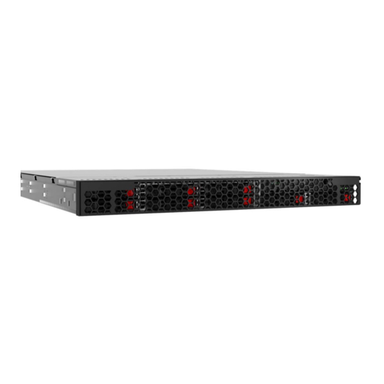
Front Panel The following information describes the front panel components for Versio systems. Figure 1-1: Versio Outer Front Panel Inner Front Panel The Versio inner front panel includes the following: • System Power (on/off) button • UID button • LED indicators •... -
Page 20: Front Panel Buttons
The control panel located on the front of the chassis has five LEDs. These LEDs provide you with critical information related to different parts of the system. Chapter 1 | Chassis Components Proprietary and Confidential © 2015 Imagine Communications Vers io H ard wa re In sta lla ti o n Man u al... -
Page 21: Sas3/Sata Leds
: The red LED indicates an SAS3/SATA drive failure. If one of the SAS3/SATA drives fail, you should be notified by your system management software. © 2015 Imagine Communications Chapter 1 | Chassis Components Proprietary and Confidential Ver sio Har dw a r e In sta ll at io n M a n ua l... -
Page 22: Disk Subsystems
Disk Subsystems This section details the Versio disk subsystems. Disk Subsystems The Versio disk subsystem is factory pre-configured and features the following RAID configuration: Organization • Server media drives (4 x 1 TB SATA drives in RAID 3) • Redundant OS and graphics media drives (6 x 120 GB SSD drives in RAID... -
Page 23: Back Panel
Back Panel The following information details the back panel components of the Versio system. Back Panel The following image shows the back panel components of the Versio system. Note that the exact device placement on your system may vary slightly from the Components graphic. -
Page 24: Broadcast I/O
: analog reference input : SDI output 3 For specification details see “Broadcast I/O” on page Chapter 1 | Chassis Components Proprietary and Confidential © 2015 Imagine Communications Vers io H ard wa re In sta lla ti o n Man u al... -
Page 25: Automation Port And Channel Assignments For Versio
Automation Port and Channel Assignments for Versio The following information outlines the port and channel assignments for preset Automation Inputs and Outputs from Versio. Automation Video I/O Type Function Notes Channel 1 (Out 1) Video Branded: Channel:1, 2, 3 • Channel 1: Live... - Page 26 AC outlets on different circuit breakers or connect the system to an Uninterruptible Power Supply (UPS). Chapter 1 | Chassis Components Proprietary and Confidential © 2015 Imagine Communications Vers io H ard wa re In sta lla ti o n Man u al...
-
Page 27: External Serial And Gpi Control
External Serial and GPI Control External control of the Versio system is available over RS-422 serial connectors and GPI (General Purpose Interface) inputs. The serial connectors and GPI outputs can also control external devices. The Versio system supports up to 8 serial connections, 8 GPI inputs, and 8 GPI outputs. The 1 RU height requires that a “fanout”... -
Page 28: Fanout Cables Lengths
). A 16 ft (485 cm) cable is also available (part number: 502120-00 502120-01 Figure 1-11. Available Fanout Cable Lengths Chapter 1 | Chassis Components Proprietary and Confidential © 2015 Imagine Communications Vers io H ard wa re In sta lla ti o n Man u al... -
Page 29: Fanout Cable Pinouts
GPO5 GPO6 GPI6 GPO6 GPO7 GPI7 GPO7 GPO8 GPI8 GPO8 © 2015 Imagine Communications Chapter 1 | Chassis Components Proprietary and Confidential Ver sio Har dw a r e In sta ll at io n M a n ua l... -
Page 30: Pinout Reference
RJ11 - 6 pos, 4 pin, 1 pair RJ14 - 6 pos, 4 pin, 2 pair RJ12 - 6 pos, 6 pin, 3 pair RJ45 - 8 pos, 8 pin, 4 pair RJ45 D-Series RJ12 ADC, Nexio, Versio RJ45 STANDARD RJ12 STANDARD HARRIS... -
Page 31: Ab4 Rj12 Gpi Pinout
There are two RJ12 to DB9 adapters available: tributary and master. Adapters Figure 1-12. RJ12 to DB9 Adapter (both models) © 2015 Imagine Communications Chapter 1 | Chassis Components Proprietary and Confidential Ver sio Har dw a r e In sta ll at io n M a n ua l... -
Page 32: Tributary Adapter: Ab4 (Master) Controlling External Device
The following is based on AB4 using the MASTER fanout cable. Harris 134-000722Q-00 MASTER SMPTE Harris DB9M RJ12F (part number: 134-000722Q-00 Chapter 1 | Chassis Components Proprietary and Confidential © 2015 Imagine Communications Vers io H ard wa re In sta lla ti o n Man u al... -
Page 33: System Installation
Chapter 2 System Installation... -
Page 34: Overview
Overview This chapter provides information about installing your Versio system, and includes the following topics: • “Chassis Components Installation” on page 33 • “Chassis Rack Installation” on page 40 • “BIOS Error Beep Codes” on page 47 Chapter 2 | System Installation Proprietary and Confidential ©... -
Page 35: Chassis Components Installation
You will need the following tools for the safe and proper installation of your system. • Phillips screw driver • Anti-static strap © 2015 Imagine Communications Chapter 2 | System Installation Proprietary and Confidential Ver sio Har dw a r e In sta ll at io n M a n ua l... -
Page 36: Install Hard Drives
Install Hard Drives The Versio comes equipped with hot-swappable hard drives. Only Harris Broadcast qualified HDDs are recommended for use in Versio chassis. Remove Hard Drive Trays from the Chassis Press the release button on the drive carrier. This extends the drive carrier handle. - Page 37 Push the hard drive into the hard drive bay until the hard drive clicks into the locked position. © 2015 Imagine Communications Chapter 2 | System Installation Proprietary and Confidential...
-
Page 38: Remove The Chassis Cover
Figure 2-3. Remove Chassis Cover Chapter 2 | System Installation Proprietary and Confidential © 2015 Imagine Communications Vers io H ard wa re In sta lla ti o n Man u al... -
Page 39: System Fans
Replace any failed fan at your earliest convenience with the same type and model. Note that the system can continue to run with a failed fan. The part number for the Versio system fan is Note: 131-100008Q01 Replace a System Fan Turn off the power to the system and unplug the system from the outlet. -
Page 40: Replace The Onboard Cr2032 Battery
Battery Holder Power Supply The Versio chassis comes equipped with two redundant 700/750W Watt power supplies. These power supplies are auto-switching capable and operate at a 100v to 240v input voltage. An amber light is illuminated on the power supply when the power is off. -
Page 41: Change The Power Supply
Release tab Pull the power supply out using the handle. Replace the failed power supply module with the same model. The part number for the Versio power supply module is Note: 122-100037-00 Push the new power supply module into the power bay until the tab clicks into the locked position. -
Page 42: Chassis Rack Installation
Determine the placement of each component in the rack before you install the rails. Chapter 2 | System Installation Proprietary and Confidential © 2015 Imagine Communications Vers io H ard wa re In sta lla ti o n Man u al... -
Page 43: Rack Mounting Considerations
Appropriate consideration of equipment nameplate ratings should be used when addressing this concern. © 2015 Imagine Communications Chapter 2 | System Installation Proprietary and Confidential Ver sio Har dw a r e In sta ll at io n M a n ua l... -
Page 44: Reliable Ground
The part number for the for Versio rack rail is Note: 149-100093Q00... -
Page 45: Install Inner Rails To The Chassis
"outward" just like the pre-attached inner rail. Slide the extension toward the front of the chassis. Secure the rail to the chassis with two screws. © 2015 Imagine Communications Chapter 2 | System Installation Proprietary and Confidential Ver sio Har dw a r e In sta ll at io n M a n ua l... -
Page 46: Install The Outer Rails To The Rack
Secure to front of rack. Attached outer rails together. Figure 2-7. Outer Rail Assembly Chapter 2 | System Installation Proprietary and Confidential © 2015 Imagine Communications Vers io H ard wa re In sta lla ti o n Man u al... -
Page 47: Install Chassis Into Rack
Align the chassis inner rails with the front of the outer rails on the rack. © 2015 Imagine Communications Chapter 2 | System Installation Proprietary and Confidential... - Page 48 (Optional) Insert and tighten the thumbscrews that hold the front of the server to the rack. Chapter 2 | System Installation Proprietary and Confidential © 2015 Imagine Communications Vers io H ard wa re In sta lla ti o n Man u al...
-
Page 49: Bios Error Beep Codes
PCI or Serial console redirection or IPMI SOL. 1 Continuous System OH System Overheat beep © 2015 Imagine Communications Chapter 2 | System Installation Proprietary and Confidential Ver sio Har dw a r e In sta ll at io n M a n ua l... - Page 50 Chapter 2 | System Installation Proprietary and Confidential © 2015 Imagine Communications Vers io H ard wa re In sta lla ti o n Man u al...
-
Page 51: Maintenance
Chapter 3 Maintenance... -
Page 52: Overview
Overview This chapter provides information about maintaining your Versio system, and includes the following topics: • “Hot Swap Power Supplies” on page 51 • “System Recovery” on page 52 • “Prevent Damage and Malfunction” on page 58 Chapter 3 | Maintenance Proprietary and Confidential ©... -
Page 53: Hot Swap Power Supplies
“Change the Power Supply” on page 39 for details on replacing a power supply module. © 2015 Imagine Communications Chapter 3 | Maintenance Proprietary and Confidential Ver sio Har dw a r e In sta ll at io n M a n ua l... -
Page 54: System Recovery
If you are using a third-party USB stick, use the following steps to format the USB stick for the WIM image. Insert the third-party USB stick into the USB port on the back of the Versio system. On the Versio system, open the Programs\PE_Apps folder. -
Page 55: Capture The Wim Image
Restart the system. Continuously press F11 during the POST to open the Boot Menu. Figure 3-2. Boot Menu © 2015 Imagine Communications Chapter 3 | Maintenance Proprietary and Confidential Ver sio Har dw a r e In sta ll at io n M a n ua l... -
Page 56: Apply The Wim Recovery Image
USB stick, you can capture the WIM image to a network share. Apply the WIM Use the following steps to apply a WIM image and restore your Versio system to the configuration captured by the WIM image. Recovery Image Insert the System Recovery USB stick containing your WIM image into the USB port on the back of the Versio system. - Page 57 From the Disk Discovery list, select the disk marked System. Figure 3-5. Select Disk Marked “System” In the Assign Letter list, select C. © 2015 Imagine Communications Chapter 3 | Maintenance Proprietary and Confidential Ver sio Har dw a r e In sta ll at io n M a n ua l...
- Page 58 The drive displays in the Step (2) field. You must use the Browse button to select the destination drive. Note: Chapter 3 | Maintenance Proprietary and Confidential © 2015 Imagine Communications Vers io H ard wa re In sta lla ti o n Man u al...
- Page 59 Eject from the menu. 21 Remove the System Recovery USB stick from the back of the system. 22 Shutdown the Versio system (Start > Shutdown). 23 Once the system has completely shut down, press the Power button on the front panel to restart the Versio system.
-
Page 60: Prevent Damage And Malfunction
Server systems waive the right for Harris Broadcast support to assist with any updates which have not been formally approved by Harris Broadcast. Chapter 3 | Maintenance Proprietary and Confidential © 2015 Imagine Communications Vers io H ard wa re In sta lla ti o n Man u al... -
Page 61: Automatic Updates
Harris Broadcast Graphics/Server systems from operating as expected. Versio systems are built on a Windows 7 ® 64-bit platform and, as such, comply with the platform design rules as they existed when the software was built. - Page 62 Chapter 3 | Maintenance Proprietary and Confidential © 2015 Imagine Communications Vers io H ard wa re In sta lla ti o n Man u al...
-
Page 63: Specifications
Chapter 4 Specifications... -
Page 64: Overview
Overview This chapter provides your Versio system specifications, and includes the following topics: • “Broadcast I/O” on page 63 • “Audio Processing” on page 65 • “SD Video Compression” on page 65 • “HD Video Compression” on page 66 •... -
Page 65: Versio System Specifications
Versio System Specifications The following specifications detail hardware and the associated capabilities for the Versio one rack unit. Some features may not be supported in all configurations; consult your sales representative for details. Specifications and designs are subject to change without notice. -
Page 66: Genlock (Ref In) Specification
• Port based aspect ratio conversion • User-based aspect ratio conversion * Versio output resolution can be set independently of input or media. Non-native content automatically converts to the selected format (HD: 1080i, 720p or SD: 525/625) via a built-in ARC and up/down converter. -
Page 67: Audio Processing
Audio Processing Table 4-3. Versio Audio Processing Specification Item Specification Channels & Formats • 8 pairs embedded per I/O channel • (4 pairs if using 24-bit PCM with SD video) Processing & • 16, 20, or 24-bit PCM, 48kHz Storage Compressed Audio •... -
Page 68: Hd Video Compression
• 1080i @ 29.97fps Mbps • 720p @ 59.94fps • 1080i @ 25fps • 720p @ 50fps Chapter 4 | Specifications Proprietary and Confidential © 2015 Imagine Communications Vers io H ard wa re In sta lla ti o n Man u al... -
Page 69: Chassis
• 6 x 40mm dual (back to back) cooling fans Regulatory • RoHS Compliances © 2015 Imagine Communications Chapter 4 | Specifications Proprietary and Confidential Ver sio Har dw a r e In sta ll at io n M a n ua l... -
Page 70: System Power
• 5% - 95% (non-condensing) Humidity Range Operating Altitude • 10,000 ft (3,048m) @ (77°F) 25°C Chapter 4 | Specifications Proprietary and Confidential © 2015 Imagine Communications Vers io H ard wa re In sta lla ti o n Man u al... -
Page 71: Integrated Devices
• 6 x 4GB DDR3 1333Mhz (PC3 10600, 24 GB) Operating System • Windows 7 64-bit © 2015 Imagine Communications Chapter 4 | Specifications Proprietary and Confidential Ver sio Har dw a r e In sta ll at io n M a n ua l... -
Page 72: Disk Subsystems
• RS-232, TCP/IP, Harris Broadcast clock interface • Read, generate and write VITC, including discontinuities Chapter 4 | Specifications Proprietary and Confidential © 2015 Imagine Communications Vers io H ard wa re In sta lla ti o n Man u al... -
Page 73: Remote Interface
Details Input/Output • RS-422 for external device control • TCP/IP socket or UDP over Ethernet for video playback, graphic branding and master control Protocols • Versio native protocol Graphic Branding Table 4-16. Graphic Branding Details Item Details Bit Depth • 32 bit •... -
Page 74: Dve (Option)
• Template defined position and motion control • Template defined crop and video resizing Chapter 4 | Specifications Proprietary and Confidential © 2015 Imagine Communications Vers io H ard wa re In sta lla ti o n Man u al... -
Page 75: Index
IPMI LAN port plug ........21 electrical safety guidelines ......10 ESD safety guidelines ........11 LEDs © 2015 Imagine Communications Index Proprietary and Confidential Ver sio Har dw a r e In sta ll at io n M a n ua l... - Page 76 ..........64 remote interface details .........71 video compression (SD) ........65 replace a failed power supply ......51 virus scan ............58 Index © 2015 Imagine Communications Vers io H ard wa re In sta lla ti o n Man u al...
- Page 77 WIM image ........52 Warning LED ..........19 initial image ..........52 WIM image .............52 Windows Automatic Updates ......58 © 2015 Imagine Communications Index Proprietary and Confidential Ver sio Har dw a r e In sta ll at io n M a n ua l...
- Page 78 Index © 2015 Imagine Communications Vers io H ard wa re In sta lla ti o n Man u al...
Need help?
Do you have a question about the Versio and is the answer not in the manual?
Questions and answers