Ricoh Aficio 200 Manuals
Manuals and User Guides for Ricoh Aficio 200. We have 3 Ricoh Aficio 200 manuals available for free PDF download: Service Manual, Reference Operation Manual
Ricoh Aficio 200 Service Manual (1024 pages)
Brand: Ricoh
|
Category: All in One Printer
|
Size: 15.75 MB
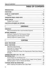
Table of Contents
Advertisement

Ricoh Aficio 200 Service Manual (29 pages)
Brand: Ricoh
|
Category: All in One Printer
|
Size: 0.99 MB
Table of Contents
Advertisement