Table of Contents
Advertisement
Quick Links
Advertisement
Table of Contents
Troubleshooting

Related Manuals for Paradyne FrameSaver FLEX 9123


Summary of Contents for Paradyne FrameSaver FLEX 9123
- Page 1 FrameSaver FLEX 9123 User’s Guide Document No. 9123-A2-GB20-20 August 2001...
- Page 2 Paradyne worldwide office locations, use one of the following methods: Internet: Visit the Paradyne World Wide Web site at www.paradyne.com. (Be sure to register your warranty at www.paradyne.com/warranty.) Telephone: Call our automated system to receive current information by fax or to speak with a company representative.
-
Page 3: Table Of Contents
Conventions Used ........1 About the FrameSaver FLEX 9123 System Overview . - Page 4 Contents 3 Configuration Basic Configuration ........Configuration Option Areas .
- Page 5 Contents 4 Security and Logins Limiting Access ......... . Controlling Asynchronous Terminal Access.
- Page 6 Contents FTP File Transfers ........5-40 Upgrading System Software .
- Page 7 Contents 7 Setting Up OpenLane for FrameSaver Devices and Activating SLV Capability OpenLane Support of FrameSaver Devices ....Setting Up the OpenLane SLM System ......Setting Up FrameSaver FLEX and SLV Support .
- Page 8 Frame Relay Link Alarm Defaults ......B-17 DLCI Alarm Defaults – Paradyne Area ..... B-19 DLCI Alarm Defaults –...
- Page 9 Contents C Connectors, Cables, and Pin Assignments Rear Panel ..........T1 Network Interface .
- Page 10 Contents viii August 2001 9123-A2-GB20-20...
-
Page 11: About This Guide
About This Guide Purpose and Intended Audience This document contains information that applies to the FrameSaver FLEX 9123 unit, which supports multiple types of service: leased line, frame relay, and managed frame relay. It is intended for system designers, engineers, administrators, and operators. - Page 12 Appendix E, Equipment List Equipment List. Index Lists key terms, acronyms, concepts, and sections. A master glossary of terms and acronyms used in Paradyne documents is → available on the World Wide Web at www.paradyne.com. Select Library → Technical Manuals...
-
Page 13: Product-Related Documents
Network Health – Traffic Accountant Reports Guide 09-10070-001 Network Health Reports Guide Complete Paradyne documentation for this product is available at www.paradyne.com. Select Library → Technical Manuals. To order a paper copy of this manual: Within the U.S.A., call 1-800-PARADYNE (1-800-727-2396) Outside the U.S.A., call 1-727-530-8623... -
Page 14: Conventions Used
About This Guide Conventions Used Convention Used to . . . Italic Indicate variable information (for example, DLCI nnnn ) . Menu selection sequence Provide an abbreviated method for indicating the selections to be made from a menu or selections from within a menu before performing a procedural step. -
Page 15: About The Framesaver Flex 9123
It is also compatible with Concord Communication’s Network Health software. FrameSaver FLEX 9123 units operate with other FrameSaver devices, and when teamed with FrameSaver devices in multinational applications, provide a complete global frame relay management solution. - Page 16 1. About the FrameSaver FLEX 9123 FrameSaver FLEX Feature Sets Depending upon the model ordered, the FrameSaver FLEX unit has the basic FrameSaver frame relay and diagnostic capability, or it is enhanced with additional SLV (Service Level Verification) reporting capability. These are referred to as feature sets, which provide different levels of intelligence for monitoring, managing, and reporting performance of the unit.
- Page 17 1. About the FrameSaver FLEX 9123 To obtain an Activation Certificate, provide the model to be upgraded (i.e., 9123), your OpenLane system license key number, and the number of FrameSaver units to be upgraded to FLEX SLV capability (the number of activations to be included on the certificate).
- Page 18 1. About the FrameSaver FLEX 9123 Basic FLEX Features The FrameSaver FLEX 9123 unit provides the following features: Easy Installation. Provides a simplified menu that allows the unit to be installed like a standard leased-line SNMP DSU/CSU, and allows selection of either leased line or frame relay service.
- Page 19 1. About the FrameSaver FLEX 9123 Auto-Configuration. Provides the following automatic configuration features: — Time Slot Discovery – For automatic configuration of all network DS0 assignments. — Frame Relay Discovery – For automatic discovery of network DLCIs and configuration of a user data port DLCIs, the PVC connection, and a management PVC, which is multiplexed with user data DLCIs.
- Page 20 1. About the FrameSaver FLEX 9123 Frame Relay Traffic Policing. Ensures proper alignment and correlation of CIR (Committed Information Rate) values between the FrameSaver unit and the network switch. When this feature is enabled, the unit can enforce CIR and EIR (Excess Information Rate), marking frames that exceed CIR as DE (Discard Eligible) using the same method used by the switch.
- Page 21 1. About the FrameSaver FLEX 9123 Advanced FLEX SLV Features The following additional features are provided with the advanced FLEX SLV feature set: TruePut™ Technology. Using Frame Delivery Ratios (FDR) and Data Delivery Ratios (DDR), throughput (within and above CIR, as well as between CIR and EIR, and above EIR) can be measured precisely, eliminating inaccuracies due to averaging.
-
Page 22: Openlane Slm System
1. About the FrameSaver FLEX 9123 OpenLane SLM System Being standards-based, the OpenLane SLM (Service Level Management) system can be used with other management applications like HP OpenView or IBM’s NetView. OpenLane includes HP OpenView adapters for integrating OpenLane features with the OpenView Web interface. -
Page 23: Netscout Manager Plus And Netscout Probes
1. About the FrameSaver FLEX 9123 NetScout Manager Plus and NetScout Probes Provides complete LAN and WAN traffic analysis and monitoring functions for FrameSaver devices. The following features are supported using this application: Thresholds for RMON 1 (Remote Monitoring, Version 1) alarms and events can be configured. - Page 24 1. About the FrameSaver FLEX 9123 1-10 August 2001 9123-A2-GB20-20...
-
Page 25: User Interface And Basic Operation
User Interface and Basic Operation This chapter tells you how to access, use, and navigate the menu-driven user interface. It includes the following: Logging On on page 2-2 Main Menu on page 2-4 Screen Work Areas on page 2-5 Navigating the Screens on page 2-6 —... -
Page 26: Logging On
2. User Interface and Basic Operation Logging On Start a session using one of the following methods: Telnet session via: — An in-band management channel through the frame relay network. — A local in-band management channel configured on the DTE port between the FrameSaver unit and the router. - Page 27 2. User Interface and Basic Operation If your login was . . . Then the . . . Valid Main Menu appears. Begin your session. NOTE: If your login is valid, but access is denied, there are two currently active sessions. Invalid Message, Invalid Password, appears on line 24, and the Login screen is redisplayed.
-
Page 28: Main Menu
2. User Interface and Basic Operation Main Menu Entry to all of the FrameSaver unit’s tasks begins at the Main Menu, which has six menus or branches. The Access Level at the top of the screen only appears when security has been set up. main Access Level: 1 9123-C-SLV... -
Page 29: Screen Work Areas
2. User Interface and Basic Operation Screen Work Areas There are two user work areas: Screen area – Where you input information into fields. Function keys area – Where you perform specific screen functions. Model Number Date and Time Menu Path main/config/system/slv 9123-C-SLV Device Name: Node A... -
Page 30: Navigating The Screens
2. User Interface and Basic Operation Screen Format Description Function Keys Area Specific functions that can be performed by pressing a specified key, then pressing Enter. Message Area System-related information and valid settings for input fields in the lower left corner. System and Test Status messages in the lower right corner. -
Page 31: Function Keys
2. User Interface and Basic Operation Function Keys All function keys (located in the lower part of the screen; see the example in Screen Work Areas on page 2-5) operate the same way throughout the screens. They are not case-sensitive, so upper- or lowercase letters can be used interchangeably. -
Page 32: Selecting From A Menu
2. User Interface and Basic Operation Selecting from a Menu Procedure To select from a menu: 1. Tab or press the down arrow key to position the cursor on a menu selection, or press the up arrow key to move the cursor to the bottom of the menu list. Each menu selection is highlighted as you press the key to move the cursor from position to position. -
Page 33: Selecting A Field
2. User Interface and Basic Operation Selecting a Field Once you reach the desired menu or screen, select a field to view or change, or issue a command. Press the Tab or right arrow key to move the cursor from one field to another. The current setting or value appears to the right of the field. - Page 34 2. User Interface and Basic Operation 2-10 August 2001 9123-A2-GB20-20...
- Page 35 Configuration This chapter includes the following: Basic Configuration on page 3-3 — Configuration Option Areas — Accessing and Displaying Configuration Options — Changing Configuration Options Saving Configuration Options — Using the Easy Install Feature on page 3-8 Setting Up So the Router Can Receive RIP on page 3-10 Entering System Information and Setting the System Clock on page 3-10...
- Page 36 3. Configuration Assigning Time Slots/Cross Connections on page 3-29 — Assigning Frame Relay Time Slots to the Network Interface — Assigning the Synchronous Data Port to Network Time Slots Clearing Assignments — Configuring Frame Relay for an Interface on page 3-34 Manually Configuring DLCI Records on page 3-37 Configuring PVC Connections...
- Page 37 3. Configuration Basic Configuration Configuration option settings determine how the FrameSaver unit operates. Use the FrameSaver unit’s Configuration Edit/Display menu to display or change configuration option settings. The Configuration Edit/Display menu of the FrameSaver 9123 is shown below. Configuration Menu main/config 9123-C-SLV Device Name: Node A...
- Page 38 The FrameSaver unit arrives with configured factory default settings, which are located in the Factory Default Configuration option area. You can find the default settings for configuration options in the: FrameSaver FLEX 9123 Quick Reference Configuration Option Tables on page 3-16 If the factory default settings do not support your network’s configuration, you can...
- Page 39 3. Configuration Accessing and Displaying Configuration Options To access and display configuration options, load (copy) the applicable configuration option set into the edit area. Procedure To load a set of configuration options for editing: 1. From the Main Menu, press the down arrow key so the cursor is on Configuration.
- Page 40 3. Configuration Changing Configuration Options Procedure To change configuration option settings: 1. From the Configuration Edit/Display menu, select a set of configuration options and press Enter. For example: Configuration → PVC Connections 2. Select the configuration options that are applicable to your network, and make Chapter 2, User Interface and appropriate changes to the setting(s).
- Page 41 3. Configuration Saving Configuration Options When changes to the configuration options are complete, use the Save function key to save your changes to either the Current, Customer 1, or Customer 2 configuration areas. NOTE: When changing settings, you must Save for changes to take effect. Procedure To save the configuration option changes: 1.
- Page 42 3. Configuration Using the Easy Install Feature The Easy Install feature allows the FrameSaver unit to be installed like a standard leased-line SNMP DSU/CSU. Once the unit is installed and minimal configuration is completed using this feature, the NOC (Network Operation Center) can complete configuration of the unit and verify the setup.
- Page 43 If you select Yes, the edit copy of the system options is updated to reflect the changed mode. A Save is required to apply option updates to the current configuration. FrameSaver FLEX 9123 Installation Instructions See the for additional information...
- Page 44 3. Configuration Setting Up So the Router Can Receive RIP Using the system’s standard Routing Information Protocol (RIP) feature, routing information is passed to the router over the management PVC, so the router can learn routes to FrameSaver FLEX and SLV devices. Node IP information should be set up (see Configuring Node IP Information on page 3-42).
- Page 45 3. Configuration Setting Up Auto-Configuration The auto-configuration feature allows you to select a method of automatic configuration and connection of DLCIs within the FrameSaver unit, as well as to automatically remove DLCIs and connections that are no longer supported by the network service provider.
- Page 46 3. Configuration Selecting a Frame Relay Discovery Mode When a Frame Relay Discovery Mode is active, the FrameSaver unit “discovers” network DLCIs from the network LMI status response message. It configures a network DLCI, a user data port DLCI, and automatically connects them to create a PVC.
- Page 47 3. Configuration NOTE: If 1MPort (the default) is not the setting required for your application, change the Frame Relay Discovery Mode before connecting the network cable or editing discovered option settings. Otherwise, the FrameSaver unit will start “discovering” DLCIs as soon as it powers up. To recover from this problem and when some DLCIs or PVC Connections have been configured manually, edit a selected “discovered”...
- Page 48 3. Configuration Automatically Removing a Circuit Using the automatic circuit removal feature, which comes enabled, network DLCIs and PVCs can be automatically removed from the unit’s configuration when the network service provider no longer supports them. Automatic deletion is based upon information from a LMI full status response on an active frame relay link.
- Page 49 3. Configuration Setting Up Back-to-Back Operation Using this special feature, you can set up two FrameSaver units that are connected back-to-back without frame relay switches between them, as in a test bench setup. Changing Operating Mode When setting up back-to-back operation: One unit must be configured for Standard operation, which is the setting for normal operation.
- Page 50 3. Configuration Configuration Option Tables Configuration option descriptions contained in this chapter are in menu order, even though this may not be the order in which you access each when configuring the unit. The following configuration option tables are included: Table 3-1, System Frame Relay and LMI Options.
- Page 51 3. Configuration Configuring Frame Relay and LMI for the System Select Frame Relay and LMI from the System menu to display or change the Frame Relay and LMI options for the entire system (see Table 3-1, System Frame Relay and LMI Options).
- Page 52 3. Configuration Table 3-1. System Frame Relay and LMI Options (2 of 3) Traffic Policing Possible Settings: Enable, Disable Default Setting: Disable Determines whether or not CIR (Committed Information Rate) and EIR (Excess Information Rate) will be enforced by the unit on frames being sent on network frame relay links.
- Page 53 3. Configuration Table 3-1. System Frame Relay and LMI Options (3 of 3) LMI Inbound Heartbeat (T2) Possible Settings: 5, 10, 15, 20, 25, 30 Default Setting: 15 Configures the LMI-defined T2 parameter, which sets the number of seconds between the receipt of status enquiry messages on the network side of the LMI.
- Page 54 3. Configuration Configuring Service Level Verification Options SLV options are selected from the System menu (see Table 3-2, Service Level Verification Options). Main Menu → Configuration → System → Service Level Verification To configure these options, Service Type on the Easy Install screen must be set to Frame Relay.
- Page 55 3. Configuration Table 3-2. Service Level Verification Options (2 of 2) SLV Timeout Clearing Event Threshold Available Settings: 1, 2, 3, 4 . . . 20 Default Setting: 1 Specifies the number of consecutive SLV messages that must be received before the DLCI Inactive status is cleared.
- Page 56 3. Configuration Configuring General System Options Select General from the System menu to configure the general system configuration options (see Table 3-3, General System Options). Main Menu → Configuration → System → General Table 3-3. General System Options Test Timeout Possible Settings: Enable, Disable Default Setting: Enable Determines whether or not loopback and pattern tests have a duration after which they...
- Page 57 3. Configuration Configuring the Physical Interfaces The following sections describe how to configure the characteristics for physical interfaces: Configuring the Network Interface Configuring the User Data Port Configuring the Network Interface When configuring the physical characteristics for the network interface, select Physical from the Network menu (see Table 3-4, Network Physical Interface Options).
- Page 58 3. Configuration Table 3-4. Network Physical Interface Options (2 of 4) Bit Stuffing Possible Settings: 62411, Disable Default Setting: 62411 Determines the type of bit insertion to provide ones density requirements for data transmitted to the network. Display Conditions – This option does not appear when Line Coding Format is set to B8ZS.
- Page 59 3. Configuration Table 3-4. Network Physical Interface Options (3 of 4) Network Initiated PLB Possible Settings: Enable, Disable Default Setting: Enable Allows the initiation and termination of the payload loopback (PLB) to be controlled by the receipt of PLB-Actuate and PLB-Release commands from the network. Display Conditions –...
- Page 60 3. Configuration Table 3-4. Network Physical Interface Options (4 of 4) Excessive Error Rate Threshold Possible Settings: 10E-4, 10E-5, 10E-6, 10E-7, 10E-8, 10E-9 Default Setting: 10E-4 Sets the error rate threshold that determines when an EER condition is declared. The excessive error rate is determined by the ratio of the number of CRC6 errors to the total number of bits received over a set period of time.
- Page 61 3. Configuration Configuring the User Data Port Select Physical from the Data Ports menu to configure the physical characteristics for the user data port (see Table 3-5, Data Port Physical Interface Options). Main Menu → Configuration → Data Ports → Physical Table 3-5.
- Page 62 3. Configuration Table 3-5. Data Port Physical Interface Options (2 of 2) Monitor RTS (Control) Possible Settings: Enable, Disable Default Setting: Enable Specifies whether the state of the Request To Send (RTS) circuits on the user data port will be used to determine when valid data communication is possible with the DTE. When the RTS off condition is detected, CTS is deasserted, LMI is declared down, and no further transfer of frame relay data can occur on this interface.
- Page 63 3. Configuration Assigning Time Slots/Cross Connections The Time Slot Assignment/Cross Connect feature provides an easy method of assigning time slots for frame relay data and creating cross-connections to the synchronous data interface. The system allows you to assign DS0s on the T1 network interface and between the user data port and network interface in order to share the T1 network.
- Page 64 3. Configuration Frame Relay Network Time Slot Assignment Screen Example main/config/tslot_assign/frame_relay 9123-C-SLV Device Name: Node A 3/20/2000 23:32 FRAME RELAY NETWORK 1 ASSIGNMENT Time Slot Discovery: Disable Available Available Available Available Available Available Available Available Available Available FrameRly1 FrameRly1 FrameRly1 FrameRly1 FrameRly1 FrameRly1 FrameRly1 FrameRly1 FrameRly1 FrameRly1 FrameRly1 FrameRly1 FrameRly1 FrameRly1 -------------------------------------------------------------------------------- Ctrl-a to access these functions, ESC for previous menu...
- Page 65 3. Configuration Procedure 1. Select Frame Relay Network Assignments. Main Menu → Configuration → Time Slot Assignment → Frame Relay Network Assignments or Main Menu → Easy Install → Time Slot Assignment Screen (When Service Type is set to Frame Relay, the default.) The Frame Relay Network Assignments screen appears.
- Page 66 3. Configuration Assigning the Synchronous Data Port to Network Time Slots If Service Type is set to Leased Line, the Sync Data Port Assignment screen appears. Use this screen to assign the synchronous data port to network interface time slots. Follow one of the following menu selection selections: Main Menu →...
- Page 67 3. Configuration Procedure 1. Select one of the following menu selection sequences: Main Menu → Configuration → Time Slot Assignment → Sync Data Port Assignments or Main Menu → Easy Install → Time Slot Assignment Screen (When Service Type is set to Leased Line.) 2.
- Page 68 3. Configuration Configuring Frame Relay for an Interface Select Frame Relay from the interface’s menu to display or change the Frame Relay options for an individual interface (see Table 3-6, Interface Frame Relay Options). Main Menu → Configuration → [Network/Data Ports] → Frame Relay To configure these options, Service Type on the Easy Install screen must be set to Configuring Frame Relay for an Interface Frame Relay.
- Page 69 3. Configuration Table 3-6. Interface Frame Relay Options (2 of 3) LMI Parameters Possible Settings: System, Custom Default Setting: System Allows you to use the system LMI options, or to set specific LMI options for this interface. System – Use system LMI options (see Table 3-1, System Frame Relay and LMI Options).
- Page 70 3. Configuration Table 3-6. Interface Frame Relay Options (3 of 3) LMI Inbound Heartbeat (T2) Possible Settings: 5, 10, 15, 20, 25, 30 Default Setting: 15 Configures the LMI-defined T2 parameter, which sets the number of seconds between the receipt of status enquiry messages on the network side of the LMI. Applies to the network side of a UNI only.
- Page 71 3. Configuration Manually Configuring DLCI Records The Auto-Configuration feature automatically configures DLCI Records and their PVC Connections. DLCI Records can also be created manually (see Table 3-7, DLCI Record Options). Main Menu → Configuration → [Network/Data Port] → DLCI Records Typically, DLCI Records only need to be configured when building Management PVCs between the NOC and the central site unit;...
- Page 72 3. Configuration Table 3-7. DLCI Record Options (2 of 3) CIR (bps) Possible Settings: 0 – 1536000 Default Setting: 64000 Determines the data rate for the DLCI that the network commits to accept and carry without discarding frames; the CIR in bits per second. Entry of an invalid rate causes the error message Value Out of Range (0 –...
- Page 73 3. Configuration Table 3-7. DLCI Record Options (3 of 3) DLCI Priority Possible Settings: Low, Medium, High Default Setting: High Specifies the relative priority for data received on the DLCI from an attached device (also known as quality of service ). All data on Port 1 is cut-through, as long as there is no higher-priority data queued from another user port.
- Page 74 3. Configuration Configuring PVC Connections The Auto-Configuration feature automatically configures PVC Connections and their DLCI Records. PVC Connections can also be created manually (see Table 3-8, PVC Connection Options). Main Menu → Configuration → PVC Connections From this screen, you can go directly to the Management PVC screen by selecting the MgmtPVCs function key for easy movement between screens.
- Page 75 3. Configuration Table 3-8. PVC Connection Options (2 of 2) Destination Link Possible Settings: Net1-FR1 Default Setting: Initially blank; no default. Specifies the frame relay interface used as the destination link; the to end of a from-to link. The only valid settings for this configuration option are frame relay interfaces that have at least one DLCI or EDLCI defined which are not part of a PVC connection or management link.
- Page 76 3. Configuration Setting Up Management and Communication Options The following sections explain options that can be selected from the Management and Communication menu: Configuring Node IP Information Configuring Management PVCs Configuring General SNMP Management Configuring Telnet and/or FTP Session Support Configuring SNMP NMS Security Configuring SNMP Traps Configuring the Ethernet Port...
- Page 77 3. Configuration Table 3-9. Node IP Options (1 of 3) Node IP Address Possible Settings: 001.000.000.000 – 223.255.255.255, Clear Default Setting: Clear (000.000.000.000) Specifies the IP address needed to access the node. Since an IP address is not bound to a particular port, it can be used for remote access via a management PVC.
- Page 78 3. Configuration Table 3-9. Node IP Options (2 of 3) Default IP Destination (continued) Ethernet – Specifies that the default destination is connected to the Ethernet port. Only appears when the Ethernet port’s Interface Status option is enabled. When selected, the Default Gateway Address must also be configured (see Table 3-15, Ethernet Port Options).
- Page 79 3. Configuration Table 3-9. Node IP Options (3 of 3) TS Management Link Access Level (continued) Level-1 – Allows Telnet or FTP access by network service providers with the capability to view unit information, change configuration options, and run tests. This is the highest access level allowed.
- Page 80 3. Configuration Configuring Management PVCs Select Management PVCs to define inband management links by adding or changing Management PVCs (see Table 3-10, Management PVC Options). First, DLCI records must have been configured for the interface where the Management Manually Configuring DLCI Records PVC will reside.
- Page 81 3. Configuration Table 3-10. Management PVC Options (2 of 3) Intf Subnet Mask Possible Settings: Node-Subnet-Mask, Calculate, Special ( nnn . nnn . nnn . nnn ) Default Setting: Node-Subnet-Mask Specifies the subnet mask associated with the IP address that is needed to access the unit when the management PVC is providing connectivity to an external IP network (through frame relay) that requires a specific subnet mask for the interface.
- Page 82 3. Configuration Table 3-10. Management PVC Options (3 of 3) Primary DLCI Possible Settings: 16 – 1007 Default Setting: Initially blank; no default. Specifies the DLCI number used for the management PVC after the frame relay interface is selected. The DLCI must be defined for the link (i.e., has a DLCI record), and it must not be part of a PVC connection or already assigned as a management PVC.
- Page 83 3. Configuration Configuring General SNMP Management Select General SNMP Management to add, change, or delete the information needed to allow the FrameSaver unit to be managed as an SNMP agent by the NMS supporting the SNMP protocols (see Table 3-11, General SNMP Management Options).
- Page 84 3. Configuration Table 3-11. General SNMP Management Options (2 of 2) Name 2 Access Possible Settings: Read, Read/Write Default Setting: Read Specifies the type of access allowed to the objects in the MIB. This is the type of access allowed for external SNMP managers accessing MIB objects using Community Name 2. Read –...
- Page 85 3. Configuration Table 3-12. Telnet and FTP Session Options (2 of 3) Session Access Level Possible Settings: Level-1, Level-2, Level-3 Default Setting: Level-1 Specifies the highest security level allowed when accessing the menu-driven user interface via a Telnet session. If a login is required for the session, the effective access level is also determined by the user’s access level.
- Page 86 3. Configuration Table 3-12. Telnet and FTP Session Options (3 of 3) FTP Session Possible Settings: Enable, Disable Default Setting: Enable Determines whether the system responds as a server when an FTP (file transfer protocol) client on an interconnected IP network requests an FTP session. This option must be enabled when downloading files.
- Page 87 3. Configuration Configuring SNMP NMS Security Select SNMP NMS Security from the Management and Communication menu to display, add, or change SNMP security configuration options for the FrameSaver unit to set up trap managers (see Table 3-13, SNMP NMS Security Options).
- Page 88 3. Configuration Table 3-13. SNMP NMS Security Options (2 of 2) Access Type Possible Settings: Read, Read/Write Default Setting: Read Specifies the type of access allowed for an authorized NMS when IP address validation is performed. Display Conditions – This option appears for each trap manager specified in the Number of Trap Managers configuration option.
- Page 89 3. Configuration Table 3-14. SNMP Traps Options (2 of 3) NMS n IP Address Possible Settings: 001.000.000.000 – 223.255.255.255, Clear Default Setting: Clear (000.000.000.000) Specifies the IP address that identifies the SNMP manager(s) to receive SNMP traps. Display Conditions – This option appears for each trap manager specified in the Number of Trap Managers configuration option.
- Page 90 3. Configuration Table 3-14. SNMP Traps Options (3 of 3) Link Traps Possible Settings: Disable, Up, Down, Both Default Setting: Both Determines whether SNMP linkDown or linkUp traps are sent to the currently configured trap manager(s). A linkDown trap indicates that the unit recognizes a failure in one of the interfaces.
- Page 91 3. Configuration Configuring the Ethernet Port Select Ethernet Port from the Management and Communication menu, or Ethernet Port Options Screen from the Easy Install screen, to configure the Ethernet port (see Table 3-15, Ethernet Port Options). Main Menu → Configuration → Management and Communication → Ethernet Port Main Menu →...
- Page 92 3. Configuration Table 3-15. Ethernet Port Options (2 of 2) Default Gateway Address Possible Settings: 001.000.000.000 – 223.255.255.255, Clear Default Setting: Clear (000.000.000.000) Specifies the IP address for the port’s default gateway. It is used for packets that do not have a route.
- Page 93 3. Configuration Configuring the Communication Port Select Communication Port from the Management and Communication menu to display or change the communication port configuration options (see Table 3-16, Communication Port Options). Main Menu → Configuration → Management and Communication → Communication Port Table 3-16.
- Page 94 3. Configuration Table 3-16. Communication Port Options (2 of 4) Stop Bits Possible Settings: 1, 2 Default Setting: 1 Determines the number of stop bits used for the COM port. 1 – Provides one stop bit. 2 – Provides two stop bits. Ignore Control Leads Possible Settings: Disable, DTR Default Setting: Disable...
- Page 95 3. Configuration Table 3-16. Communication Port Options (3 of 4) Inactivity Timeout Possible Settings: Enable, Disable Default Setting: Enable Determines whether a user session is disconnected after a specified time of inactivity (no keyboard activity). Display Conditions – This option only appears when Port Use is set to Terminal. Enable –...
- Page 96 3. Configuration Table 3-16. Communication Port Options (4 of 4) Possible Settings: None, Standard_out Default Setting: None Specifies which Routing Information Protocol (RIP) is used to enable routing of management data between devices. Display Conditions – This option only appears when Port Use is set to Net Link. None –...
- Page 97 3. Configuration Configuring the COM Port to Support an External Modem Select External Modem (Com Port) to display or change the configuration options that control call processing for an external device attached to the COM port (see Table 3-17, External Modem (COM Port) Options).
- Page 98 3. Configuration 3-64 August 2001 9123-A2-GB20-20...
- Page 99 Security and Logins This chapter includes the following: Limiting Access on page 4-2 Controlling Asynchronous Terminal Access on page 4-2 Controlling External COM Port Device Access on page 4-4 Controlling Telnet or FTP Access on page 4-4 Limiting Telnet Access —...
-
Page 100: Security And Logins
4. Security and Logins Limiting Access The FrameSaver unit provides access security on the following interfaces: Asynchronous (async) terminal Telnet SNMP Up to two direct or Telnet sessions can be active at any given time; that is, you can have two simultaneous Telnet sessions, or one Telnet session and one active asynchronous terminal session, or two simultaneous asynchronous terminal sessions. - Page 101 4. Security and Logins Procedure To limit asynchronous terminal access to the menu-driven user interface: 1. Select the Communication Port options. Main Menu → Configuration → Management and Communication → Communication Port 2. Set the following configuration options, as appropriate. To .
-
Page 102: Controlling External Com Port Device Access
4. Security and Logins Controlling External COM Port Device Access Dial-in access can be controlled when an external device (modem) is connected to the unit’s communication (COM) port. The External Device Commands option must be set to AT. Procedure To control dial-in access: 1. -
Page 103: Limiting Telnet Access
4. Security and Logins Limiting Telnet Access Telnet access can be limited by: Disabling Telnet access completely. Requiring a login for Telnet sessions that are not on the TS Management Link. Assigning an access level for Telnet sessions. Disabling TS Management Link access. To limit Telnet access via a service provider’s troubleshooting management link, Limiting Telnet or FTP Access Over the TS Management Link on page 4-7. -
Page 104: Limiting Ftp Access
4. Security and Logins Limiting FTP Access FTP access can be limited by: Disabling FTP access completely. Requiring a user ID and password to login. Limiting FTP bandwidth. Procedure To limit FTP access when the session is not on the TS Management Link: 1. -
Page 105: Limiting Telnet Or Ftp Access Over The Ts Management Link
4. Security and Logins Limiting Telnet or FTP Access Over the TS Management Link Procedure To limit Telnet or FTP access when the session is on the TS Management Link: 1. Select the Telnet and FTP Session options. Main Menu → Configuration → Management and Communication → Telnet and FTP Sessions 2. -
Page 106: Controlling Snmp Access
4. Security and Logins Controlling SNMP Access The FrameSaver unit supports SNMP Version 1, which provides limited security through the use of community names. There are three methods for limiting SNMP access: Disabling SNMP access. Assigning SNMP community names and the access type. Assigning IP addresses of those NMSs that can access the unit. -
Page 107: Assigning Snmp Community Names And Access Levels
4. Security and Logins Assigning SNMP Community Names and Access Levels The FrameSaver unit supports the SNMP protocol and can be managed by an SNMP manager. SNMP manager access can be limited by: Assigning the SNMP community names that are allowed to access the FrameSaver unit’s Management Information Base (MIB). -
Page 108: Limiting Snmp Access Through Ip Addresses
4. Security and Logins Limiting SNMP Access Through IP Addresses An additional level of security is provided by: Limiting the IP addresses of NMSs that can access the FrameSaver unit. Performing validation checks on the IP address of SNMP management systems attempting to access the FrameSaver unit. -
Page 109: Creating A Login
4. Security and Logins Creating a Login A login is required if security is enabled. (Security is enabled by the configuration options Login Required for the communication port, modem port, and Telnet Login Required or FTP Login Required for a Telnet or FTP Session.) Up to six login ID/password combinations can be created using ASCII text, and each login must have a specified access level. -
Page 110: Modifying A Login
4. Security and Logins Modifying a Login Logins are modified by deleting the incorrect login and creating a new one. Deleting a Login Procedure To delete a login record: 1. Select Administer Logins. Main Menu → Control → Administer Logins 2. -
Page 111: Operation And Maintenance
Operation and Maintenance This chapter includes the following information: Displaying System Information on page 5-2 Viewing LEDs and Control Leads on page 5-3 — LED Descriptions — Control Lead Descriptions Device Messages on page 5-7 Status Information on page 5-12 —... - Page 112 5. Operation and Maintenance FTP File Transfers on page 5-40 — Upgrading System Software — Determining Whether a Download Is Complete Changing Software — Transferring Collected Data — Displaying System Information Use the Identity screen to view identification information about the FrameSaver unit.
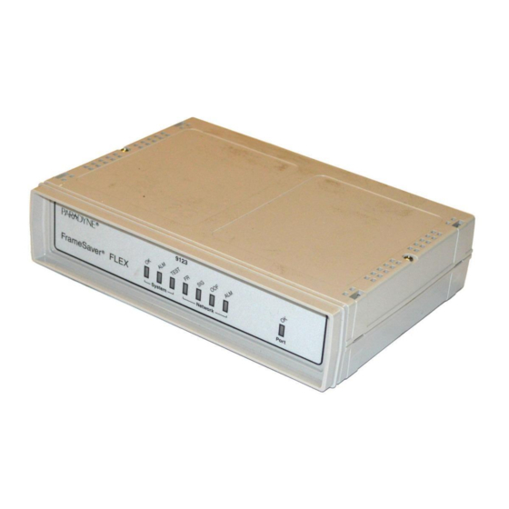
- Page 113 5. Operation and Maintenance Viewing LEDs and Control Leads The FrameSaver 9123 unit’s faceplate includes LEDs (light-emitting diodes) that provide status on the unit and its interfaces. 9123-C FrameSaver FrameSaver FLEX ® System Network Port 00-16707 The Display LEDs and Control Leads screen allows you to monitor a remote unit and is useful when troubleshooting control lead problems.
- Page 114 5. Operation and Maintenance LED Descriptions The following table identifies the alarms that cause the Alarm LED to light. See Table 5-2, Network Interface LEDs, and Table 5-3, User Data Port LED, for network and user data port interface LED information. Table 5-1.
- Page 115 5. Operation and Maintenance Table 5-2. Network Interface LEDs Label Indication Color What It Means Signal Green ON – A recoverable signal is present on the network interface. OFF – The signal cannot be recovered from the network interface. An LOS condition exists. Out of Frame Yellow ON –...
- Page 116 5. Operation and Maintenance Control Lead Descriptions Table 5-2, Network Interface LEDs, for a description of these leads. See Table 5-3, User Data Port LED, to interpret the user data port OK control lead. The LED descriptions and control lead descriptions are the same. In addition to these LEDs, additional control leads can be monitored through the Display LEDs and Control Leads screen.
-
Page 117: Device Messages
5. Operation and Maintenance Device Messages These messages appear in the messages area at the bottom of the screens. All device messages are listed in alphabetical order. Table 5-5. Device Messages (1 of 5) Message What It Indicates What To Do Access level is n , User’s access level is 2 No action is needed. - Page 118 5. Operation and Maintenance Table 5-5. Device Messages (2 of 5) Message What It Indicates What To Do Duplicate DLCI DLCI number entered is not No action is needed; previous Number unique for the frame relay contents of the DLCI number field link.
- Page 119 5. Operation and Maintenance Table 5-5. Device Messages (3 of 5) Message What It Indicates What To Do Limit of Mgmt PVCs New was selected from the Do not create the management reached PVC Connection Table and PVC. the m×aximum number of Delete another management management PVCs has PVC, and try again.
- Page 120 5. Operation and Maintenance Table 5-5. Device Messages (4 of 5) Message What It Indicates What To Do No Primary New or Modify was selected Configure additional DLCIs for the Destination Link DLCIs from the PVC Connection network link and try again. Available Table, but even though If a network DLCI has been...
- Page 121 5. Operation and Maintenance Table 5-5. Device Messages (5 of 5) Message What It Indicates What To Do Save Cancelled Changes were made on the No action is needed. Easy Install screen, but when it came to saving the changes, the Esc key was pressed or No was entered in response to the Save Changes? prompt.
-
Page 122: Status Information
5. Operation and Maintenance Status Information Status information is useful when monitoring the FrameSaver unit. The following illustration shows the Status menu for the FrameSaver 9123 unit. Status Menu main/status 9123-C-SLV Device Name: Node A 3/26/2000 23:32 STATUS System and Test Status LMI Reported DLCIs PVC Connection Status Time Slot Assignment Status... -
Page 123: System And Test Status Messages
5. Operation and Maintenance System and Test Status Messages System and test status information is selected from the Status menu. Main Menu → Status → System and Test Status The following information is included on this screen: Self-Test Results Messages Last System Reset Date and Time Health and Status Messages Test Status Messages... - Page 124 5. Operation and Maintenance Health and Status Messages The following table provides Health and Status messages that apply to the FrameSaver 9123 unit. Table 5-7. Health and Status Messages (1 of 3) Message What It Indicates AIS at Network 1 An Alarm Indication Signal (AIS) is received by the network interface.
- Page 125 5. Operation and Maintenance Table 5-7. Health and Status Messages (2 of 3) Message What It Indicates Lease Line Mode Active The FrameSaver unit is configured for leased line operation (see Service Type on the Easy Install screen). Link Down Administratively, The specified frame relay link has been disabled by frame relay link the unit due to LMI Behavior conditions or LMI...
- Page 126 5. Operation and Maintenance Table 5-7. Health and Status Messages (3 of 3) Message What It Indicates SLV Timeout, DLCI nnnn , An excessive number of SLV communication 1, 2, 3 frame relay link responses from the remote FrameSaver SLV unit have been missed on the specified multiplexed DLCI;...
- Page 127 5. Operation and Maintenance Test Status Messages These test messages appear in the right column of the System and Test Status screen. You have the option of allowing the test to continue or aborting the test. Chapter 6, Troubleshooting , for more information on tests, including how to start and stop them.
-
Page 128: Network Lmi-Reported Dlcis Status
5. Operation and Maintenance Network LMI-Reported DLCIs Status Network LMI-reported DLCI statuses are selected from the Status menu. Main Menu → Status → LMI Reported DLCIs The LMI Reported DLCIs screen displays the status and CIR (if supported by the switch) for each DLCI, whether the DLCI is configured or not. - Page 129 5. Operation and Maintenance Table 5-9. Network LMI-Reported DLCIs Status Field Status What It Indicates DLCI 16 through 1007 Identifies the Local Management Interface-reported DLCI numbers assigned to the selected interface – the identifying number assigned to the path between two frame relay FrameSaver units’...
-
Page 130: Pvc Connection Status
5. Operation and Maintenance PVC Connection Status PVC connection statuses are selected from the Status menu. Main Menu → Status → PVC Connection Status Only PVC connections with Source DLCIs configured to be Active are shown. This screen only appears when Service Type is set to Frame Relay. PVC Connection Status Screen Example main/status/connections 9123-C-SLV... - Page 131 5. Operation and Maintenance Table 5-10. PVC Connection Status (2 of 2) Field Status What It Indicates EDLCI 0 to 62 For multiplexed DLCIs only. Identifies an individual link/ connection embedded within a DLCI. Status Identifies whether the physical interfaces, LMIs, and DLCIs are all enabled and active for this PVC connection.
-
Page 132: Time Slot Assignment Status
5. Operation and Maintenance Time Slot Assignment Status Time Slot assignments are made using the Time Slot Assignment configuration Assigning Time Slots/Cross Connections in Chapter 3, Configuration , option. See for making time slot assignments. Use the Timeslot Assignment Status screen to display time slot assignments for the network channels. - Page 133 5. Operation and Maintenance The following information is available for network interface time slots (N01– N24): The Cross Connect Status Field (bottom) . . . Indicates . . . Unassgn The time slot is unassigned. FrameRly1 The time slot is assigned to the network frame relay link.
-
Page 134: Ip Routing Table
5. Operation and Maintenance IP Routing Table Use the IP Routing Table to see all the routes configured in the FrameSaver unit. Main Menu → Status → IP Routing Table IP Routing Table Screen Example main/status/ip_rout 9123-C-SLV Device Name: Node A 3/26/2000 23:32 Page 1 of 2 IP ROUTING TABLE... - Page 135 5. Operation and Maintenance Table 5-11. IP Routing Table Values (2 of 2) Column What It Indicates Type The method used to add the route to the table. RIP: The route was discovered through Routing Information Protocol. The route remains until its TTL (Time to Live) expires, a better route is provided via RIP, or there is a power reset.
-
Page 136: Performance Statistics
5. Operation and Maintenance Performance Statistics Use the Performance Statistics menu to display statistical information for a selected interface. Statistical information is useful when trying to determine the severity and frequency or duration of a condition. Main Menu → Status → Performance Statistics Physical and link layer statistics (Layers 1 and 2) are collected on the port. -
Page 137: Clearing Performance Statistics
5. Operation and Maintenance Clearing Performance Statistics Performance statistics counters can be reset to the baseline when using a directly-connected asynchronous terminal and your security Access Level is Level-1. This feature is useful when troubleshooting problems. Statistic counters are not actually cleared using this feature. True statistic counts are always maintained so SLAs can be verified, and they can be viewed from an SNMP NMS. -
Page 138: Service Level Verification Performance Statistics
5. Operation and Maintenance Service Level Verification Performance Statistics These statistics appear when Service Level Verification (SLV) is selected from the Performance Statistics menu. Main Menu → Status → Performance Statistics → Service Level Verification They only appear for the network interface and only if DLCIs are multiplexed. In addition, this screen only appears for units with the FLEX SLV feature set, when Service Type is set to Frame Relay. - Page 139 5. Operation and Maintenance Table 5-12. Service Level Verification Performance Statistics (2 of 2) Statistic What It Indicates Inbound Dropped Total number of bytes transmitted by the far-end device that were Characters * dropped in transit. The counts continue to increment until the maximum value is reached (2 –2), then the count starts over.
-
Page 140: Dlci Performance Statistics
5. Operation and Maintenance The statistics collected by the unit depend upon the device at the far end of the connection. If the far-end device is a FrameSaver SLV unit, frame relay, latency, and FDR/DDR (Frame Relay Delivery Ratio [delivered frames/offered frames]; Data Delivery Ratio [delivered octets/offered octets]) performance statistics are collected. - Page 141 5. Operation and Maintenance Table 5-13. DLCI Performance Statistics (2 of 2) Statistic What It Indicates With BECN Set The number of frames and octets sent on the selected DLCI of the frame relay link with backward explicit congestion notifications. BECNs are sent to notify users of data traffic congestion in the opposite direction of the frame carrying the BECN indicator.
-
Page 142: Frame Relay Performance Statistics
5. Operation and Maintenance Frame Relay Performance Statistics The following statistics appear when Frame Relay is selected from the Performance Statistics menu. Main Menu → Status → Performance Statistics → Frame Relay All counts continue to increment until the maximum value is reached (2 –2), then the count starts over. - Page 143 5. Operation and Maintenance Table 5-14. Frame Relay Performance Statistics (2 of 3) Statistic What It Indicates Frame Relay Errors (continued) Short Rx Frames The number of frames received over the Network or Port-1 interface that were less than 5-octets (five 8-bit bytes) in length. There may be a non-frame relay device on the other end of the link.
- Page 144 5. Operation and Maintenance Table 5-14. Frame Relay Performance Statistics (3 of 3) Statistic What It Indicates Frame Relay HDLC Errors Rx Total Errors The number of receiver errors on the interface. The following are included in this count: Receive invalid frames (short frames, long frames, invalid DLCIs, unknown DLCIs, and unknown errors) Rx Total Discards Receive errors (non-octet aligned frames, frames with CRC...
-
Page 145: Esf Line Performance Statistics
5. Operation and Maintenance ESF Line Performance Statistics These statistics appear when ESF Line is selected from the Performance Statistics menu for the network interface. Main Menu → Status → Performance Statistics → ESF Line Only seven T1 network statistical intervals appear on the screen at any one time. You can choose which intervals to display on your screen by entering: Interval Number (01–96) –... - Page 146 5. Operation and Maintenance ESF Line Performance Statistics Screen Example main/status/performance/esf 9123-C-SLV Device Name: Node A 3/26/2000 23:32 Network 1 ESF LINE PERFORMANCE STATISTICS Current Interval Timer ESF Error Events Near=123 Far = 124 Near = 15 Far = 12 ---ES-- --UAS-- --SES--...
- Page 147 5. Operation and Maintenance The following performance statistics are collected for ESF line conditions. Statistic What It Indicates Errored Seconds (ES) Any second with one or more ESF Error events. Unavailable Seconds Any second in which service is unavailable. Begins incrementing (UAS) at the onset of 10 consecutive seconds of severely errored seconds (SES), and stops incrementing after 10 consecutive...
-
Page 148: Ethernet Performance Statistics
5. Operation and Maintenance Ethernet Performance Statistics The following statistics appear when Ethernet is selected from the Performance Statistics menu. Main Menu → Status → Performance Statistics → Ethernet Statistic What It Indicates Port Rate (Mbps) The operating rate as detected on the Ethernet port. One of the following may appear for this statistic: Disconnected –... -
Page 149: Trap Event Log
5. Operation and Maintenance Trap Event Log The Trap Event Log displays all traps stored in the SNMP trap event log. The following log example describes the alarm conditions that will generate an SNMP trap for a physical interface, and for the frame relay LMIs and DLCIs. These alarm conditions also generate Health and Status messages seen on the System and Test Status screen. -
Page 150: Ftp File Transfers
5. Operation and Maintenance FTP File Transfers The FrameSaver unit supports a standard File Transfer Protocol (FTP) server over Transmission Control Protocol (TCP). A complete binary image of the configuration files can be copied to a host to provide a backup. To use this feature, the unit must be configured to support Telnet and FTP Sessions. - Page 151 5. Operation and Maintenance Procedure To initiate an FTP session: 1. Start the FTP client program on your host. For example, on a UNIX host, type ftp, followed by the FrameSaver unit’s IP address. 2. If a login and password are required (see Creating a Login in Chapter 4, Security and Logins ), you are prompted to enter them.
-
Page 152: Upgrading System Software
5. Operation and Maintenance Upgrading System Software If you need to upgrade the FrameSaver unit’s program code, you must transfer the upgrade of the nam.ocd file in the system memory directory using the put command. NOTE: Upgrades can be performed through the network using a Management PVC, or through the COM port if Port Use is set to Net Link (see Table 3-16, in Chapter 3, Configuration ). -
Page 153: Determining Whether A Download Is Complete
5. Operation and Maintenance Determining Whether a Download Is Complete To see whether a download has completed, check the Identity screen. Main Menu → Status → Identity Check Alternate Software Rev. under the NAM Identity column. If a software revision number appears, the file transfer is complete. If In Progress appears, the file is still being transferred. -
Page 154: Transferring Collected Data
5. Operation and Maintenance Transferring Collected Data SLV user history statistics and LMI packet capture data can be uploaded to an NMS or a Network Associates Sniffer using FTP, which is faster than other methods. The rate at which the data file is transferred is the rate set by the FTP Max Transfer Rate (Kbps) option (see Table 3-12, Telnet and FTP Session in Chapter 3, Configuration) . -
Page 155: Troubleshooting
Troubleshooting This chapter includes the following: Problem Indicators on page 6-2 Resetting the Unit and Restoring Communication on page 6-3 — Resetting the Unit from the Control Menu — Resetting the Unit By Cycling the Power Restoring Communication with a Misconfigured Unit —... - Page 156 6. Troubleshooting Physical Tests on page 6-20 — Line Loopback — Payload Loopback Repeater Loopback — Send Line Loopback — — Data Channel Loopbacks on a Frame Relay Link — Send and Monitor Pattern Tests — DTE Loopback IP Ping Test on page 6-28 Lamp Test on page 6-30...
- Page 157 6. Troubleshooting Resetting the Unit and Restoring Communication You can reset the unit in one of four ways: Reset it from the Control menu. Cycle the power. Reset the configuration options for the COM port, or reload the factory default settings.
- Page 158 6. Troubleshooting Restoring Communication with a Misconfigured Unit Misconfiguring the unit could render the menu-driven user interface inaccessible. If this occurs, connectivity to the unit can be restored via a directly connected asynchronous terminal. Procedure To reset COM port settings: 1.
- Page 159 6. Troubleshooting Troubleshooting Management Link Feature A dedicated troubleshooting management link is available to help service providers isolate device problems within their networks. This feature allows Telnet or FTP access to the unit on this link. Troubleshooting over this link is essentially transparent to customer operations.
- Page 160 6. Troubleshooting Viewing Captured Packets from the Menu-Driven User Interface The twelve most recent LMI events are stored in the trace log. Once the capture buffer or trace log is full, the oldest packets are overwritten. To view the most recently captured packets using the menu-driven user interface: LMI Packet Capture Utility →...
- Page 161 6. Troubleshooting Alarms Table 6-1, Alarm Conditions, describes the alarm conditions that will generate an SNMP trap for a physical interface, and the frame relay LMIs and DLCIs. These alarm conditions also generate Health and Status messages seen on the System and Test Status screen.
- Page 162 6. Troubleshooting Table 6-1. Alarm Conditions (2 of 4) Alarm Condition What It Indicates What To Do Link Down The specified frame relay Verify that the network LMI is up. If Administratively, link has been disabled by it is, contact your network frame relay link the unit due to LMI Behavior provider.
- Page 163 6. Troubleshooting Table 6-1. Alarm Conditions (3 of 4) Alarm Condition What It Indicates What To Do LOS at Network 1 A Loss of Signal (LOS) condition is detected on the network interface. Clears when the ratio of ones to zeros received is greater than or equal to 12.5%.
- Page 164 6. Troubleshooting Table 6-1. Alarm Conditions (4 of 4) Alarm Condition What It Indicates What To Do SLV Timeout, An excessive number of Verify that the network LMI is up. If DLCI nnnn , SLV communication it is, contact your network service frame relay link responses from the remote provider.
-
Page 165: Viewing The Trap Event Log
6. Troubleshooting Viewing the Trap Event Log The Trap Event Log displays all traps stored in the SNMP trap event log. ASCII trap strings used to describe trap events are provided in the tables contained in Standards Compliance for SNMP Traps in Appendix B, SNMP MIBs and Traps, and RMON Alarm Defaults . - Page 166 6. Troubleshooting Table 6-2. Device Problems (2 of 2) Symptom Possible Cause Solutions Failure xxxxxxxx The unit has detected an Record the 8-digit code from appears at the top of internal software failure. the System and Test Status the System and Test screen.
-
Page 167: Frame Relay Pvc Problems
6. Troubleshooting Frame Relay PVC Problems Table 6-3. Frame Relay PVC Problems Symptom Possible Cause Solutions No receipt or Cross Connection of the Verify the PVC connections transmission of data DLCIs are configured and DLCIs by checking the incorrectly. network-discovered DLCIs on the LMI Reported DLCIs screen. -
Page 168: Tests Available
6. Troubleshooting Tests Available The following tests are available to a FrameSaver FLEX 9123. Test Menu Example main/test 9123-C-SLV Device Name: Node A 3/26/2000 23:32 TEST Network PVC Tests Data Port PVC Tests Network Physical Tests Data Port Physical Tests... -
Page 169: Test Timeout Feature
6. Troubleshooting Test Timeout Feature A Test Timeout feature is available to automatically terminate a test (as opposed to manually terminating a test) after it has been running a specified period of time. It is recommended that this feature be used when the FrameSaver unit is remotely managed through an inband data stream (PVC). -
Page 170: Aborting All Tests
6. Troubleshooting Procedure To start and stop a loopback or a set-pattern test: 1. Follow this menu selection sequence: Main Menu → Test 2. Select an interface and test (e.g., Network or Data Port PVC Tests) and press Enter. The selected test screen appears. Start appears in the Command column. Inactive appears in the Status column. -
Page 171: Pvc Tests
6. Troubleshooting PVC Tests PVC tests can be run on a requested DLCI for a selected interface. The FrameSaver unit must be operating in frame relay mode. When PVC tests are on a multiplexed DLCI between FrameSaver devices, they are nondisruptive to data, so user data can continue to be sent during a test. -
Page 172: Pvc Loopback
6. Troubleshooting PVC Loopback The PVC Loopback loops frames back to the selected interface on a per-PVC basis. This test logically (not physically) loops back frames received from another FrameSaver device through the selected frame relay PVC to the same device. Main Menu →... -
Page 173: Monitor Pattern
6. Troubleshooting Monitor Pattern This test monitors packets filled with a hexadecimal 55 test pattern and sequence number over the selected interface and DLCI to another FrameSaver device. To monitor a pattern test on a link: Main Menu → Test → [Network PVC Tests/Data Port PVC Tests] The current number of sequence and data errors are shown under the Result column when the FrameSaver unit is in sync. -
Page 174: Physical Tests
6. Troubleshooting Physical Tests A FrameSaver 9123 unit’s physical tests screen for the network interface is shown below. Main Menu → Test → [Network Physical Tests/Data Port Physical Tests] This example shows the Network Physical Tests screen, for the model with 64 PVCs and the FLEX SLV upgrade. -
Page 175: Line Loopback
6. Troubleshooting Line Loopback The local Line Loopback (LLB) loops the information received on the selected interface back to the source of the loopback. When used with a pattern test at the remote node, LLB determines whether the problem is with the sending device or the T1 facility. -
Page 176: Payload Loopback
6. Troubleshooting Payload Loopback The local Payload Loopback (PLB) loops the information received on the selected interface back to the network after it has passed through the receive and transmit framing section of the device. Use the PLB to determine whether the problem is with the T1 facility or in the circuitry of the remote device. -
Page 177: Repeater Loopback
6. Troubleshooting Repeater Loopback The local Repeater Loopback (RLB) loops data received from the user data port after the signal has passed through the framing circuitry. Use the RLB to ensure that all of the data is correct up to the point where it is sent over the interface. This helps to indicate that the FrameSaver unit is operational. -
Page 178: Send Line Loopback
6. Troubleshooting Send Line Loopback The remote Line Loopback (LLB) up and down codes are in-band codes that allow control of a remote device. The LLB Up code invokes a line loopback in the remote unit while the LLB Down code terminates the remote line loopback. Network loopbacks are defined in AT&T TR 62411. -
Page 179: Data Channel Loopbacks On A Frame Relay Link
6. Troubleshooting Data Channel Loopbacks on a Frame Relay Link A network-initiated Data Channel Loopback (DCLB) that loops data over the frame relay link (DS0s) received on the network interface through the FrameSaver unit’s framing circuitry and back to the same interface. A DCLB can be controlled over the frame relay link using one of the following in-band methods: V.54 Loopback. -
Page 180: Send And Monitor Pattern Tests
6. Troubleshooting Send and Monitor Pattern Tests The pattern tests enable a FrameSaver unit to either send or monitor a known bit pattern. These tests generate industry-standard bit patterns that can be used to determine whether information is being correctly transmitted across a circuit. The following test patterns are available: —... -
Page 181: Dte Loopback
6. Troubleshooting DTE Loopback The local DTE external Loopback (DTLB) test loops the received signal on the DTE interface back to the DTE without affecting the operation of the remaining ports. Use this test to isolate problems on the user data port. Main Menu →... -
Page 182: Ip Ping Test
6. Troubleshooting IP Ping Test An IP Ping test can be run to test connectivity between the FrameSaver unit and any FrameSaver unit, router, or NMS to which it has a route. In addition, the test can be run to access a remote unit for configuration purposes. Times when you might want to run an IP Ping test are: To test connectivity between the FrameSaver unit and any FrameSaver unit in Procedure 1... - Page 183 6. Troubleshooting Procedure 2 To ping the NMS at the central site: 1. Verify that the central site NMS has the FrameSaver unit’s IP address in its routing table so it can communicate with the FrameSaver unit. 2. Verify that the central site NMS’s router has the FrameSaver unit’s IP address in its routing table so it can communicate with the FrameSaver unit.
-
Page 184: Lamp Test
6. Troubleshooting Lamp Test The FrameSaver unit supports a Lamp Test to verify that all LEDs are lighting and functioning properly. All LEDs flash or blink on and off at the same time every 1/2 second during execution of the test. When the test is stopped, the LEDs are restored to their normal condition. - Page 185 Setting Up OpenLane for FrameSaver Devices and Activating SLV Capability This chapter includes: OpenLane Support of FrameSaver Devices on page 7-1 Setting Up the OpenLane SLM System on page 7-2 Setting Up FrameSaver FLEX and SLV Support on page 7-3 Ordering FLEX SLV Activations on page 7-4 To Find Your License Key Number...
-
Page 186: Setting Up Openlane For Framesaver Devices And Activating Slv Capability
7. Setting Up OpenLane for FrameSaver Devices and Activating SLV Capability Web-based diagnostic tests: end-to-end, PVC loopbacks, connectivity, and physical interface tests Basic device configuration, including RMON alarm and threshold configuration when the unit has the advanced FLEX SLV feature set activated Automatic device and PVC discovery for SLV devices with their SLV Delivery Ratio configuration option enabled Easy firmware downloads to an entire network or parts of the network... -
Page 187: Setting Up Framesaver Flex And Slv Support
7. Setting Up OpenLane for FrameSaver Devices and Activating SLV Capability Setting Up FrameSaver FLEX and SLV Support With OpenLane SLM’s extensive online Help, the application is self-documenting and you have access to the most current system information. Procedure To set up FrameSaver FLEX and FLEX SLV support: 1. -
Page 188: Ordering Flex Slv Activations
If your network service provider (NSP) manages the network, contact the service provider. If you are a network service provider or distributor, contact Paradyne at 1-800-727-2396, www.paradyne.com, via a purchase order, or your Electronic Data Interchange (EDI). If submitting a purchase order by fax, send it to 1-727-532-5270. -
Page 189: The Activation Certificate
7. Setting Up OpenLane for FrameSaver Devices and Activating SLV Capability The Activation Certificate An Activation Certificate will be sent to you via Federal Express. NOTE: If you ordered an Activation Certificate via e-mail, Activation Certificate information will be e-mailed to you so you can start activating units immediately. -
Page 190: Administering And Managing Flex Slv Activations
7. Setting Up OpenLane for FrameSaver Devices and Activating SLV Capability Administering and Managing FLEX SLV Activations The OpenLane SLM system provides the following features that allow you to administer and manage your Activation Certificates and FLEX SLV activations. From the Firmware/Feature Maintenance menu, you can: Add or view the status of activations, and see how many activations remain on each certificate. -
Page 191: Entering An Activation Certificate
7. Setting Up OpenLane for FrameSaver Devices and Activating SLV Capability Entering an Activation Certificate Once you receive an Activation Certificate, enter the Activation Certificate number into your OpenLane SLM system’s database. Procedure To enter the Activation Certificate number: 1. Open the OpenLane SLM application and provide your access level, which must be Admin. -
Page 192: Scheduling Activations
7. Setting Up OpenLane for FrameSaver Devices and Activating SLV Capability Scheduling Activations You can activate one, many, or all FrameSaver devices at any time, until all the activations ordered for the certificate have been completed. NOTE: Once SLV capability is activated in a FrameSaver device, the unit cannot be returned to a non-SLV state. -
Page 193: Checking The Status Of Scheduled Activations
7. Setting Up OpenLane for FrameSaver Devices and Activating SLV Capability Checking the Status of Scheduled Activations You can check the status of scheduled activations or cancel activations at any time prior to the activations taking place by selecting View/Abort scheduled task status from the Firmware/Feature Maintenance menu. - Page 194 7. Setting Up OpenLane for FrameSaver Devices and Activating SLV Capability 7-10 August 2001 9123-A2-GB20-20...
-
Page 195: Setting Up Netscout Manager Plus For Framesaver Devices
Setting Up NetScout Manager Plus for FrameSaver Devices This chapter includes NetScout Manager Plus information as it relates to FrameSaver FLEX devices. It includes the following: Preparation on page 8-2 Configuring NetScout Manager Plus on page 8-3 — Adding FrameSaver FLEX Units to the NetScout Manager Plus Network —... - Page 196 A template of alarms and values for configuring alarms and several templates for creating history files specific to the FrameSaver unit are available. OpenLane paradyne directories include the following: Properties: paradyne.fsd file found in OpenLane/netscout/alarms/directory Properties: paradyne.fst file found in OpenLane/netscout/alarms/directory...
- Page 197 8. Setting Up NetScout Manager Plus for FrameSaver Devices Configuring NetScout Manager Plus For the NetScout Manager Plus main window to appear, make sure your environment is set up exactly as specified in your NetScout Readme file. You need Copy the OpenLane directory to a user directory. Add frame relay agents to the NetScout Manager.
- Page 198 — IP address — Enter 1 for the frame relay logical interface to be monitored. — Properties File: Select paradyne. 7. Select the OK button at the bottom of the screen to add the agent, discover its DLCIs, and return to the Configuration Manager main window.
- Page 199 DLCI. OpenLane provides a template for configuring alarms. DLCI alarms can be configured manually, but using the Paradyne alarm defaults template greatly reduces configuration time. The following alarms are configured for each DLCI included in the Paradyne MIB: — Frames Sent (SLVFramesSnt) — Rx DLCI Utilization (SLVrxDLCIUtil) —...
- Page 200 8. Setting Up NetScout Manager Plus for FrameSaver Devices Editing Alarms Procedure 1. From the NetScout Manager Plus main window, with the FrameRelay and Admin radio buttons still selected, click on the Config Manager icon to open the Configuration Manager main window. 2.
- Page 201 8. Setting Up NetScout Manager Plus for FrameSaver Devices 4. Edit any trap defaults that may be required. See Step 4 of Adding SLV Alarms Manually for field settings you may want to change. 5. Select the OK button (at the bottom of the screen) to apply your changes. The window closes and the Configuration Manager main window reappears.
- Page 202 8. Setting Up NetScout Manager Plus for FrameSaver Devices Adding SLV Alarms Manually For FrameSaver units with the SLV and SLM Reporting feature set, once DLCIs have been discovered, SLV alarms should be defined and assigned to each DLCI. When configuring alarms manually, every alarm must be configured for each DLCI; that is, if there are eight alarms and 20 DLCIs, 160 trap configurations must be created (8 x 20).
- Page 203 Select or Enter . . . Domain User Defined DLCI DLCI number for trap being assigned Stats Type PARADYNE Trap Variable Trap variable to be configured Key1 The ifIndex for the frame relay logical interface is 1 Key2 DLCI number (same as DLCI above)
- Page 204 8. Setting Up NetScout Manager Plus for FrameSaver Devices Creating History Files Up to 14 additional user history tables can be created in the FrameSaver unit for each interface. An interface is a specific DLCI or the entire frame relay interface. A table must be created for each DLCI or frame relay link to be monitored.
- Page 205 8. Setting Up NetScout Manager Plus for FrameSaver Devices Procedure 1. Open a terminal window and go to $NSHOME/usr. 2. Copy an example or interface-specific file to a new file that contains the user history table number. 3. Open the new file using a text editor. The variables in the file are listed with their OIDs (Object IDs).
- Page 206 8. Setting Up NetScout Manager Plus for FrameSaver Devices Installing the User-Defined History Files Once the user-defined history files have been created, the files need to be installed. History files are installed from the command-line prompt in NetScout Manager Plus. Should the FrameSaver unit be reset, these files will need to be reinstalled.
-
Page 207: Monitoring A Dlci's History Data
8. Setting Up NetScout Manager Plus for FrameSaver Devices Monitoring a DLCI’s History Data Once the monitoring variables have been defined, a problem DLCI can monitored. Procedure To monitor user history data: 1. From the NetScout Manager Plus main window, with the FrameRelay radio button still selected, select the Traffic radio button. - Page 208 8. Setting Up NetScout Manager Plus for FrameSaver Devices 5. Select History List from the View menu. The History List window opens. The newly defined user history variables should appear on this list. 6. Highlight the desired set of user history variables, and select the OK button. Data is gathered based upon the configured user history variables.
- Page 209 8. Setting Up NetScout Manager Plus for FrameSaver Devices Using the 2D or 3D Bar to view the user history data collected, you can click on a particular bar and get an expanded view of the data. 8. Click anywhere on this window to return to the previous window view (see Step 7 of this procedure).
-
Page 210: Monitoring The Agent Using Netscout Manager Plus
8. Setting Up NetScout Manager Plus for FrameSaver Devices Monitoring the Agent Using NetScout Manager Plus Once the FrameSaver FLEX agent has been added to NetScout Manager Plus, select either the Traffic or Protocol radio button to monitor the newly added agent, or one of its DLCIs. - Page 211 8. Setting Up NetScout Manager Plus for FrameSaver Devices Procedure 1. Select the Traffic radio button to monitor the newly added agent, or one of its DLCIs. 2. Highlight an agent in the agent list box so that its DLCIs appear in the DLCI list box (under the agent list box).
- Page 212 8. Setting Up NetScout Manager Plus for FrameSaver Devices 8-18 August 2001 9123-A2-GB20-20...
- Page 213 Setting Up Network Health for FrameSaver Devices FrameSaver units are compatible with Concord Communication’s Network Health software. For FrameSaver units with the SLV and SLM reporting feature set, Network Health has released the first in a series of software modules that integrate FrameSaver SLV enhanced performance statistics into its reporting package (see the example FrameSaver SLV Plus At-a-Glance Report on page 9-9).
-
Page 214: Setting Up Network Health For Framesaver Devices
9. Setting Up Network Health for FrameSaver Devices Installation and Setup of Network Health Refer to the Network Health Installation Guide for installation instructions, and follow the instructions applicable to your network platform. Once Network Health is installed, you need to set up the application so it will support FrameSaver units. Each Network Health application provides a different set of functions, called a module. -
Page 215: Discovering Framesaver Elements
9. Setting Up Network Health for FrameSaver Devices Discovering FrameSaver Elements Once licenses are entered and you have access to the applications, the Discover dialog box opens. Use this dialog box to search for FLEX units in your network and discover their DLCIs. -
Page 216: Configuring The Discovered Elements
9. Setting Up Network Health for FrameSaver Devices Configuring the Discovered Elements Network Health sets the speed for discovered elements when it polls the unit for the first time. For a FrameSaver FLEX unit, the speed set would be the unit’s CIR. No additional configuration should be required. -
Page 217: Grouping Elements For Reports
9. Setting Up Network Health for FrameSaver Devices Grouping Elements for Reports Once the discovery process is completed and required changes are made, the newly discovered elements (DLCIs) should be organized into a group for Health reporting. Grouping makes for easier monitoring and management of similar node types (e.g., all FLEX and SLV elements). -
Page 218: Generating Reports For A Group
9. Setting Up Network Health for FrameSaver Devices Generating Reports for a Group Once Network Health has had sufficient time to gather data from the polled DLCIs and the DLCIs have been grouped, you can start generating reports. When selecting a report Section, select WAN from the drop-down list. See Running Reports from the Console in the Network Health Reports Guide for additional information. -
Page 219: About Trend Reports
9. Setting Up Network Health for FrameSaver Devices About Trend Reports By specifying specific variables like bandwidth, trend analysis can be performed and shown on Trend Reports. Up to ten variables for a DLCI, or ten DLCIs on one variable can be generated on a single trend report. Information can be presented in a line graph, pie chart, bar chart, or table format. - Page 220 9. Setting Up Network Health for FrameSaver Devices — Elements Summary Report – Compares DLCI traffic with volume and the baseline, bandwidth utilization, and errors. Use this report for DLCI detail information and comparison, to identify DLCIs with above or below average volume so they can be investigated when there are any significant changes.
- Page 221 9. Setting Up Network Health for FrameSaver Devices — FrameSaver SLV Plus At-a-Glance Report For FrameSaver units with the SLV and SLM reporting feature set, performs trend analysis on up to ten specified variables for DLCIs. This is the first Network Health report to integrate the FrameSaver FLEX SLV unit’s unique monitoring capabilities, using the unit’s SLV-advanced network statistics.
- Page 222 9. Setting Up Network Health for FrameSaver Devices Trend Reports – Perform trend analysis on up to ten specified variables for DLCIs. Variables other than bandwidth can be selected for a trend report (e.g., burst octets), but a bandwidth trend report should be generated when investigating problems that appear on Exceptions Reports, Supplemental Reports, and Health reports.
-
Page 223: A Menu Hierarchy
Menu Hierarchy Menus The following menus are a graphical representation of the FrameSaver FLEX 9123 unit’s menu organization. The following menu structures are shown: Frame Relay mode on page A-2 Leased Line mode on page A-4 9123-A2-GB20-20 August 2001... - Page 224 A. Menu Hierarchy Menu Hierarchy – Frame Relay Mode MAIN MENU Status Status Test System and Test Status LMI Reported DLCIs Configuration PVC Connection Status Auto-Configuration Timeslot Assignment Status Control IP Routing Table Easy Install Performance Statistics Trap Event Log Display LEDs and Control Leads Identity...
- Page 225 A. Menu Hierarchy MAIN MENU Status Test Configuration Auto-Configuration Auto-Configuration • Frame Relay Discovery Mode Control • Automatic Circuit Removal Easy Install MAIN MENU Status Test Configuration Auto-Configuration Control Control System Information Easy Install Administer Logins Change Operating Mode Select Software Release LMI Packet Capture Utility Disconnect Modem Reset Device...
- Page 226 A. Menu Hierarchy Menu Hierarchy – Leased Line Mode MAIN MENU Status Status Test System and Test Status Timeslot Assignment Status Configuration IP Routing Table Control Performance Statistics Easy Install Display LEDs and Control Leads Identity System and Timeslot IP Routing Performance Identity Test Status...
- Page 227 A. Menu Hierarchy MAIN MENU Status Test Configuration Control Control System Information Easy Install Administer Logins Select Software Release Disconnect Modem Reset Device System Information Administer Logins Select Software Release • Device Name • Login ID • Current Release • System Name, •...
- Page 228 A. Menu Hierarchy August 2001 9123-A2-GB20-20...
- Page 229 FrameSaver Unit’s sysDescr (system 1) FrameSaver Unit’s sysObjectID (system 2) — Interfaces Group (mib-2) on page B-4 — Paradyne Indexes to the Interface Table (ifTable) — NetScout Indexes to the Interface Table (ifTable) Standards Compliance for SNMP Traps on page B-6 Trap: warmStart —...
-
Page 230: Mib Support
Enterprise MIB RMON Version 1 MIB (RFC 1757) RMON Version 2 MIB (RFC 2021) Downloading MIBs and SNMP Traps Paradyne standard and enterprise MIBs are available from the Paradyne World Wide Web site. Procedure To access Paradyne MIBs: 1. Access the Paradyne World Wide Web site at www.paradyne.com. -
Page 231: System Group (Mib-2)
The following is the system description (sysDescr [system 1]) for the NMS subsystem in the FrameSaver 9123 unit: PARADYNE T1 FrameSaver Flex; Model: 9123-C; S/W Release: (MM.mm.bb [MM=Major.mm=minor.bb=build] format) ; NAM CCA number: (hardware version in hhhh-hhh format) ; Serial number: sssssss FrameSaver Unit’s sysObjectID (system 2) -
Page 232: Interfaces Group (Mib-2)
RFC 1213, which is an SNMPv1 MIB, is provided in this section. Paradyne Indexes to the Interface Table (ifTable) The following table provides the ifName for each interface type, the ifDescr, and the ifIndex that Paradyne has assigned to each. Table B-1. Paradyne Interface Objects Information... -
Page 233: Netscout Indexes To The Interface Table (Iftable)
B. SNMP MIBs and Traps, and RMON Alarm Defaults NetScout Indexes to the Interface Table (ifTable) For remote monitoring at sites where FrameSaver units are operating with NetScout Probes, use the following ifName, ifDescr, and ifIndex. Table B-2. NetScout Interface Objects Information ifName Description ifDescr (ifEntry 2) -
Page 234: Standards Compliance For Snmp Traps
B. SNMP MIBs and Traps, and RMON Alarm Defaults Standards Compliance for SNMP Traps This section describes the FrameSaver unit’s compliance with SNMP format standards and with its special operational trap features. All traps have an associated string to help you decipher the meaning of the trap. Strings associated with an interface with a substring containing $ifString have the following format: ‘DLCI $dlciNumber “$circuitId”... - Page 235 B. SNMP MIBs and Traps, and RMON Alarm Defaults Trap: warmStart This trap indicates that the FrameSaver unit has been reset and has stabilized. Table B-3. warmStart Trap Trap What It Indicates Possible Cause warmStart FrameSaver unit has just Reset command sent. reinitialized and stabilized Power disruption.
- Page 236 B. SNMP MIBs and Traps, and RMON Alarm Defaults Traps: linkUp and linkDown These traps are supported on the following interfaces: Physical sublayer interfaces: network, Ethernet, and synchronous data ports Frame relay logical link layer interfaces Table B-5. linkUp and linkDown Traps Trap What It Indicates Possible Cause...
- Page 237 B. SNMP MIBs and Traps, and RMON Alarm Defaults Table B-6. linkUp and linkDown Variable-Bindings (1 of 2) Interface Variable-Bindings Possible Cause Physical Sublayer Network ifIndex (RFC 1573) linkDown – One or more alarm conditions are active on the (Supported by the ifAdminStatus interface.
- Page 238 B. SNMP MIBs and Traps, and RMON Alarm Defaults Table B-6. linkUp and linkDown Variable-Bindings (2 of 2) Interface Variable-Bindings Possible Cause Physical Sublayer (cont'd) Ethernet Port ifIndex (RFC 1573) linkDown – Communication is not possible over the Ethernet ifAdminStatus port.
- Page 239 B. SNMP MIBs and Traps, and RMON Alarm Defaults Traps: enterprise-Specific These traps indicate that an enterprise-specific event has occurred. Supported enterprise-specific traps are listed below. Table B-7. enterprise-Specific Traps and Variable-Bindings (1 of 3) Trap Variable-Bindings Possible Cause enterpriseCIR- devFrExtDlciIfIndex CIR has changed due to the LMI Change(15)
- Page 240 B. SNMP MIBs and Traps, and RMON Alarm Defaults Table B-7. enterprise-Specific Traps and Variable-Bindings (2 of 3) Trap Variable-Bindings Possible Cause enterpriseMissedSLV- devFrExtDlciIfIndex SLV Timeout Error Event Down(16) (devFrExt.mib) Threshold has been exceeded. String: devFrExtDlciDlci (devFrExt.mib) ‘SLV down on $ifString due to excessive SLV packet loss.
- Page 241 B. SNMP MIBs and Traps, and RMON Alarm Defaults Table B-7. enterprise-Specific Traps and Variable-Bindings (3 of 3) Trap Variable-Bindings Possible Cause enterpriseTest- For physical interfaces and At least one test has been started Start(5) frame relay links: on an interface or virtual circuit. String: ifIndex (RFC 1573) ‘$testString test started on...
- Page 242 B. SNMP MIBs and Traps, and RMON Alarm Defaults Traps: RMON-Specific Two traps are defined to support the Alarm and Events Groups of RMON. See RMON Alarm and Event Defaults on page B-15 for the default values that will generate RMON-specific traps. Table B-8.
-
Page 243: Rmon Alarm And Event Defaults
FrameSaver unit, shows the alarm and event types, the interval used when generating alarms, and thresholds. Physical Interface Alarm Defaults Frame Relay Link Alarm Defaults DLCI Alarm Defaults – Paradyne Area DLCI Alarm Defaults – NetScout Area Standards Compliance for SNMP Traps on page B-6 for information about... - Page 244 B. SNMP MIBs and Traps, and RMON Alarm Defaults Physical Interface Alarm Defaults This alarm only applies to the FrameSaver unit’s network interface. Table B-9. Network Physical Interface Alarm Defaults Rising Falling Sample Event Threshold Threshold Item Type MIB/Tag/OID Interval Type Default Default...
- Page 245 B. SNMP MIBs and Traps, and RMON Alarm Defaults Frame Relay Link Alarm Defaults These alarms apply to the FrameSaver unit’s frame relay link interfaces. They are created during RMON initialization. Table B-10. Frame Relay Link Alarm Defaults (1 of 2) Rising Falling Sample...
- Page 246 B. SNMP MIBs and Traps, and RMON Alarm Defaults Table B-10. Frame Relay Link Alarm Defaults (2 of 2) Rising Falling Sample Event Threshold Threshold Item Type MIB/Tag/OID Interval Type Default Default Rx Overruns MIB: pdn_FrExt.mib (E) 900 secs Rising (15 mins) Tag: devFrExtLinkRxOverruns OID: .1.3.6.1.4.1.1795.2.24.2.
- Page 247 These alarms apply to all DLCIs on the network interface and can be created during RMON initialization or when a DLCI is created. They are put into the Paradyne alarm area. Table B-11. DLCI Alarm Defaults – Paradyne Area Rising Falling...
- Page 248 SLA between the customer and service provider. Up to eight alarms per interface are allowed. Any additional alarms are added to the Paradyne Area alarms and they cannot be changed using NetScout software. Editing Alarms in Chapter 8, Setting Up NetScout Manager Plus for FrameSaver Devices .
- Page 249 B. SNMP MIBs and Traps, and RMON Alarm Defaults Table B-12. Static DLCI Alarm Defaults – NetScout Area (2 of 2) Rising Falling Sample Event Threshold Threshold Item Type MIB/Tag/OID Interval Type Default Default Tx Frames MIB: pdn_FrExt.mib (E) 60 secs None Must be Exceeding CIR...
-
Page 250: Object Id Cross-References (Numeric Order)
B. SNMP MIBs and Traps, and RMON Alarm Defaults Object ID Cross-References (Numeric Order) The FrameSaver unit supports automatic generation of RMON alarm and event information. Each alarm sets an SNMP variable to monitor. When the threshold set for the monitored variable is exceeded, an SNMP trap is sent and/or a log entry is made. - Page 251 B. SNMP MIBs and Traps, and RMON Alarm Defaults Table B-14. History OID Cross-Reference (1 of 5) Object ID (OID) Item MIB/Tag .1.3.6.1.2.1.2.2.1..1.3.6.1.2.1.2.2.1.5.I Link Speed MIB: MIB II (RFC 1573) Tag: ifSpeed .1.3.6.1.2.1.2.2.1.10.I All DLCI + LMI Rx Octets MIB: MIB II (RFC 1573) Tag: ifInOctets MIB: MIB II (RFC 1573)
- Page 252 B. SNMP MIBs and Traps, and RMON Alarm Defaults Table B-14. History OID Cross-Reference (2 of 5) Object ID (OID) Item MIB/Tag .1.3.6.1.4.1.1795.2.24.2.6.9.4..1.3.6.1.4.1.1795.2.24.2.6.9.4.1.1.3.I.D DLCI CIR MIB: pdn_FrExt.mib (E) Tag: devFrExtDlciFrCIR .1.3.6.1.4.1.1795.2.24.2.6.9.4.1.1.7.I.D Tx DEs MIB: pdn_FrExt.mib (E) Tag: devFrExtDlciTxDE MIB: pdn_FrExt.mib (E) .1.3.6.1.4.1.1795.2.24.2.6.9.4.1.1.8.I.D Tx BECNs...
- Page 253 B. SNMP MIBs and Traps, and RMON Alarm Defaults Table B-14. History OID Cross-Reference (3 of 5) Object ID (OID) Item MIB/Tag .1.3.6.1.4.1.1795.2.24.2.6.9.4 ..1.3.6.1.4.1.1795.2.24.2.6.9.4.1.1.57.I.D Network Frames Dropped MIB: pdn_FrExt.mib (E) Above CIR Within EIR Tag: devFrExtDlciRxFrNetDrop- CirToEir .1.3.6.1.4.1.1795.2.24.2.6.9.4.1.1.59.I.D Network Frames Offered Above MIB: pdn_FrExt.mib (E)
- Page 254 B. SNMP MIBs and Traps, and RMON Alarm Defaults Table B-14. History OID Cross-Reference (4 of 5) Object ID (OID) Item MIB/Tag .1.3.6.1.4.1.1795.2.24.2.6.9.4.5.2.1..1.3.6.1.4.1.1795.2.24.2.6.9.4.5.2.1.2.I.D.N Burst Upper Limit MIB: pdn_FrExt.mib (E) (1–5) Tag: devFrExtBurstUpLimit .1.3.6.1.4.1.1795.2.24.2.6.9.4.5.2.1.3.I.D.N Burst Octets MIB: pdn_FrExt.mib (E) (1–5) Tag: devFrExtBurstOctets MIB: pdn_FrExt.mib (E)
- Page 255 B. SNMP MIBs and Traps, and RMON Alarm Defaults Table B-14. History OID Cross-Reference (5 of 5) Object ID (OID) Item MIB/Tag .1.3.6.1.4.1.1795.2.24.2.6.9.4.10.3.1..1.3.6.1.4.1.1795.2.24.2.6.9.4.10.3.1.2.I.N Port Burst Upper Limits (1–4) MIB: pdn_FrExt.mib (E) Tag: devFrExtLinkUtilUpLimit .1.3.6.1.4.1.1795.2.24.2.6.9.4.10.3.1.3.I.N Rx Port Burst Octets MIB: pdn_FrExt.mib (E) (1–5) Tag: devFrExtLinkUtilRxOctets...
- Page 256 B. SNMP MIBs and Traps, and RMON Alarm Defaults Table B-15. Alarm OID Cross-Reference (1 of 2) Object ID (OID) Item MIB/Tag .1.3.6.1.2.1.10.32.2.1..1.3.6.1.2.1.10.32.2.1.4.I.D Rx FECNs MIB: FR DTE MIB (RFC 2115) Tag: frCircuitReceivedFECNs .1.3.6.1.2.1.10.32.2.1.5.I.D Rx BECNs MIB: FR DTE MIB (RFC 2115) Tag: frCircuitReceivedBECNs MIB: FR DTE MIB (RFC 2115) .1.3.6.1.2.1.10.32.2.1.6.I.D...
- Page 257 B. SNMP MIBs and Traps, and RMON Alarm Defaults Table B-15. Alarm OID Cross-Reference (2 of 2) Object ID (OID) Item MIB/Tag .1.3.6.1.4.1.1795.2.24.2.6.9.4..1.3.6.1.4.1.1795.2.24.2.6.9.4.3.1.7.I.D Current Latency MIB: pdn_FrExt.mib (E) Tag: devFrExtLatencyLatest .1.3.6.1.4.1.1795.2.24.2.6.9.4.4.2.1.2.I.N Frame Size Upper Limits MIB: pdn_FrExt.mib (E) (1–5) Tag: devFrExtFrameSzUpLimit MIB: pdn_FrExt.mib (E)
- Page 258 B. SNMP MIBs and Traps, and RMON Alarm Defaults B-30 August 2001 9123-A2-GB20-20...
-
Page 259: C Connectors, Cables, And Pin Assignments
Connectors, Cables, and Pin Assignments This appendix shows the FrameSaver unit’s rear panel, and the pin assignments for the connectors/interfaces and cables. Rear Panel The following illustration shows the FrameSaver 9123 unit’s rear panel. ETHERNET POWER 00-16690 The sections that follow provide pin assignments for each interface. NOTE: In the pin assignment tables of this appendix, if the pin number is not shown, it is not being used. -
Page 260: T T1 Network Interface
C. Connectors, Cables, and Pin Assignments T1 Network Interface The T1 network interface/connector is an RJ48C 8-position keyed modular jack. T1 Network Cable (Feature No. 3100-F1-500) Network access is via a 20-foot cable with an RJ48C unkeyed plug-type connector on each end. The following table shows pin assignments and the purpose of each. Function Circuit Direction... -
Page 261: Com Port Connector
C. Connectors, Cables, and Pin Assignments COM Port Connector The following table provides the pin assignments for the FrameSaver unit’s 25-position EIA-232C communication port connector. Signal Direction Pin # Shield (GND) — DCE Transmit Data (TXD) From DTE (In) DCE Receive Data (RXD) To DTE (Out) DCE Request To Send (RTS) From DTE (In) -
Page 262: Standard Eia-232-D Crossover Cable
C. Connectors, Cables, and Pin Assignments Standard EIA-232-D Crossover Cable A standard crossover cable can be used to connect the COM port to an external modem. The external modem must be configured so it is compatible with Configuring an External Modem the FrameSaver unit. -
Page 263: Configuring An External Modem
C. Connectors, Cables, and Pin Assignments Configuring an External Modem Procedure To configure an external modem: 1. Disconnect the asynchronous terminal from the standard cable. See Standard EIA-232-D Crossover Cable on page C-4 for an illustration of the COM Port connection. -
Page 264: Data Port Connector
C. Connectors, Cables, and Pin Assignments Data Port Connector The following table provides the pin assignments for the 34-position V.35 connector to the DTE. 34-Pin Signal ITU CT# Direction Socket Shield — Signal Ground/Common — Request to Send (RTS) To DSU (In) Clear to Send (CTS) From DSU (Out) Data Set Ready (DSR) -
Page 265: Ethernet Port Connector
C. Connectors, Cables, and Pin Assignments Ethernet Port Connector The following table provides the pin assignments for the FrameSaver unit’s 8-position RJ45 Ethernet port unkeyed modular jack. Signal Direction Pin # 10BaseT Transmit Data (TD +) To LAN Interface (Out) 10BaseT Transmit Data (TD –) To LAN Interface (Out) 10BaseT Receive Data (RD +) - Page 266 C. Connectors, Cables, and Pin Assignments August 2001 9123-A2-GB20-20...
-
Page 267: D Technical Specifications
Technical Specifications Table D-1. FrameSaver FLEX 9123 Technical Specifications (1 of 2) Specification Criteria Approvals FCC Part 15 Class A digital device FCC Part 68 Refer to the equipment’s label for the Registration Number. Industry Canada Refer to the equipment’s label for the Certification Number. - Page 268 D. Technical Specifications Table D-1. FrameSaver FLEX 9123 Technical Specifications (2 of 2) Specification Criteria T1 Network Interface 8-position modular unkeyed USOC RJ48C jack Data rates Up to 1.536 Mbps Services supported Fractional T1 service, frame relay service Physical interface (USA)
- Page 269 E-2 for cables you can order. Model/Feature Description Number FrameSaver FLEX Units FrameSaver FLEX 9123 T1 Remote Site with 64 PVCs and 9123-A1-213 Basic FLEX Feature Set. Includes 1-Slot Housing, 120 Vac Power Supply, Network Cable, Installation Instructions, and Quick Reference.
- Page 270 E. Equipment List Model/Feature Description Number NMS Products OpenLane Enterprise 7805-D1-001 OpenLane Workgroup 7805-D1-003 NetScout Manager Plus – For UNIX or Windows NT 9180 NetScout Server – For UNIX or Windows NT 9190 NetScout WebCast – For UNIX or Windows NT 9155 Optional Features Wall Mounting Kit for 1-Slot Housing...
- Page 271 Index Numerics inverse, 1-4 55 hexadecimal Proxy, 3-58 test pattern, 6-18–6-19 assign community names and access levels, 4-9 frame relay time slots, 3-29 aborting tests, 6-16 synchronous data port, 3-32 Access time slots and cross connections, 3-29 Dial-In, 3-63 AT commands, 3-63 Easy, 3-8 At-a-Glance Reports, 9-6 Name, 3-49...
- Page 272 Index Character Connectivity Length, 3-59 test, 6-19 Control matching, 2-9 keys, 2-6 automatic determination, 1-5 lead descriptions, 5-6 enforcement, 3-18 Leads statistics, 5-28 Ignore, 3-60 CIR (bps), 3-38 Leads and LEDs, 5-3 Circuit Identifier, 3-26 menu/branch, 2-4 circuit multiplexed PVCs, 6-19 controlling Clearing asynchronous terminal access, 4-2...
- Page 273 Index Device messages, 5-7 EDLCI, 3-48 troubleshooting problems, 6-11 Destination, 3-41 Dial-In Access, 3-63 Source, 3-40 disabling SNMP access, 4-8 Discard Eligible (DE), 3-47 at Network, 5-14, 6-7 Disconnect LED, 5-4–5-5 Time (Minutes), 3-51, 3-61 linkDown trap, B-9 discovering elements/DLCIs, 9-3 EIA-232C Discovery COM Port connector, C-3...
- Page 274 Index Health and Status, 6-2 messages, 5-14 faceplate, 5-3 history FDR, 1-7 adding files, 8-10 feature sets installing files, 8-12 advanced FLEX SLV, 1-2 monitoring DLCI, 8-13 basic FLEX, 1-2 Hop, 5-24 field is blank/empty, 2-9 file transfer, 5-40 protocol, 3-52 FR Mode ICMP LED, 5-4...
- Page 275 Index local external DTE loopback, 3-28 Lamp Test, 5-17, 6-30 locked out, 4-3, 4-11, 6-4 last reset, 5-13 logging in, 2-2 latency, 1-7 logging out, 2-3 Leased Line Login, 4-1 mode, 3-9 creating, 4-11 LEDs, 6-2, 6-11 ID, 4-11 and control leads modifying and deleting, 4-12 displaying, 5-3 Required, 3-50, 3-60, 4-3, 4-5–4-6...
- Page 276 Index messages Network Device, 5-7 assigning data port to time slots, 3-32 cable pin assignments, C-2 Health and Status, 5-14 Self-Test Results, 5-13 Com Link Down, 5-15, 6-9 system, 2-6 configuring the interface, 3-23 System and Test Status, 5-13 DLCI records Test Status, 5-17 options, 3-37 Health (Concord) reports, 9-1...
- Page 277 Index problem indicators, 6-2 product-related documents, xi packet capture Proprietary RIP, 3-48, 3-55, 3-62 uploading data, 5-44 Protocol utility, 6-5 address resolution, 1-4, 3-58 packets, 3-47 LMI, 3-34 Parity, 3-59 Routing Information (RIP), 3-48, 3-62 pass-through operation, 3-9 Simple Network Management (SNMP), 3-49 Password, 4-11 Proxy ARP, 3-58 patents, A...
- Page 278 Index RJ45 setting Ethernet Port connector, C-7 Date & Time (system clock), 3-10 date and time, 3-10 RJ48C network cable, C-2 RLB, 6-23 setting up RMON auto-configuration, 3-11 alarm and event defaults, B-15 SNMP trap managers, 3-53 Specific Traps, B-14 so router can receive RIP, 3-10 Traps, 3-56 user history collection, 1-6–1-7...
- Page 279 Index statistics, 1-7, 5-26 elements, 9-3 LMI Inbound Heartbeat, 3-19, 3-36 selecting performance intervals for display, 5-35 uploading to an NMS, 5-44 LMI N4 Measurement Period, 3-19, 3-36 Status tab key, 2-6 Activation Certificates, 7-7 Tc, 3-38 checking TCP, 5-40 scheduled activations, 7-9 Telnet checking Activation Certificate, 7-7...
- Page 280 Index Transmit Clock Invert, 3-27 UNI, 3-18–3-19, 3-35–3-36 Source, 3-27 upgrading Transmit Timing, 3-24 system software, 5-42 transparent operation, 3-9 uploading data, 5-44 Trap user history Event Log, 5-39, 6-11 adding files, 8-10 Managers installing files, 8-12 Number of, 3-54 monitoring DLCI, 8-13 Traps statistics gathering, 1-6–1-7...