Table of Contents
Advertisement
Advertisement
Table of Contents

Related Manuals for Omron GX-ID1611


Summary of Contents for Omron GX-ID1611
- Page 1 EtherCAT Remote I/O Terminal GX-series EtherCAT Slave Units ® User’s Manual GX-ID GX-OD GX-OC GX-MD GX-AD GX-DA GX-EC GX-ILM XWT-ID XWT-OD Digital I/O Units Analog I/O Units Encoder Input Units IO-Link Master Unit W488-E1-09...
- Page 2 No patent liability is assumed with respect to the use of the information contained herein. Moreover, because OMRON is constantly striving to improve its high-quality products, the information contained in this manual is subject to change without notice. Every precaution has been taken in the preparation of this manual. Neverthe- less, OMRON assumes no responsibility for errors or omissions.
-
Page 3: Gx-Series Ethercat Slave Unit User's Manual
GX-series EtherCAT Slave Units User’s Manual Revised October 2018... -
Page 5: Gx-Series Ethercat Slave Unit User's Manual
Introduction Thank you for purchasing a GX-series EtherCAT Slave Unit. This manual contains information you need to know to use the EtherCAT Slave Unit. Before use, please make sure that you thoroughly read the manual and have a full understanding of the products functions and performance. - Page 6 ) to AWG20 (0.5mm AXF12142 Sheath diameter: 1.2 to 2.0 mm AWG28 (0.08mm ) to AWG24 (0.2mm AXF12146 Yellow Sheath diameter: 0.7 to 1.2 mm OMRON connectors Model Specification Applicable wire range Spring AWG28 (0.08mm ) to AWG20 (0.5mm XN2A-1430 clamp type Sheath diameter: 1.5 mm max.
-
Page 7: Icon
Icon The meanings of the icons used in this manual are as follows. Precautions for Safe Use Indicates precautions on what to do and what not to do to ensure using the product safely. Precautions for Correct Use Indicates precautions on what to do and what not to do to ensure proper operation and perfor- mance. - Page 8 Structure of This Manual This manual consists of the following chapters. Chapters Contents Chapter 1 EtherCAT Network Explains about the EtherCAT features and the network configuration. Chapter 2 EtherCAT Slave Unit Overviews the GX-series EtherCAT Slave Unit and its various types. Chapter 3 Basic Usage Procedures Explains the setup method and usage procedures by using...
-
Page 9: Terms And Conditions Agreement
Omron’s exclusive warranty is that the Products will be free from defects in materials and workman- ship for a period of twelve months from the date of sale by Omron (or such other period expressed in writing by Omron). Omron disclaims all other warranties, express or implied. -
Page 10: Application Considerations
Disclaimers Performance Data Data presented in Omron Company websites, catalogs and other materials is provided as a guide for the user in determining suitability and does not constitute a warranty. It may represent the result of Omron’s test conditions, and the user must correlate it to actual application requirements. Actual perfor- mance is subject to the Omron’s Warranty and Limitations of Liability. -
Page 11: Safety Precautions
Safety Precautions Labels and Meanings to Ensure Safe Usage To ensure safe usage of the EtherCAT Slave Unit, the precautions in this manual are displayed with the following labels and symbols. The precautions explained in this section describe important information regarding safety. These pre- cautions must be followed without fail. - Page 12 WARNING Do not attempt to take any Unit apart and do not touch the interior of any Unit while the power is being supplied. Also, do not turn ON the power supply while the cover is open. Doing any of these may result in electric shock. Do not attempt to disassemble, repair, or modify any Units.
- Page 13 The CPU Unit refreshes I/O even when the program is stopped (i.e., even in PRO- GRAM mode). Confirm safety thoroughly in advance before changing the status of any part of memory allocated to I/O Units, Special I/O Units, or CPU Bus Units. Any changes to the data allocated to any Unit specifically the Special I/O Units/CPU Bus Units may result in unexpected operation of the loads connected to the Unit.
-
Page 14: Precautions For Safe Use
Precautions for Safe Use Observe the following precautions when using the Unit. Power Supply • Always use the power supply voltage specified in this manual. An incorrect voltage may result in malfunction or burning. • Take appropriate measures to ensure that the specified power with the rated voltage and fre- quency is supplied. - Page 15 • Do not apply voltages to the Input Slave Units in excess of the rated input voltage. Excess voltage or loads may result in burning. • Do not apply voltages or connect loads to the Outputs Slave Units in excess of the maximum switching capacity.
-
Page 16: Precautions For Correct Use
Precautions for Correct Use • Wire all connections correctly according to instructions in this manual. Failure to install them may result in serious accidents. • Do not operate the control system in the following locations: • Location subject to direct sunlight. •... -
Page 17: Regulations And Standards
Whether the products conform to the standards in the system used by the customer, however, can- not be checked by OMRON and must be checked by the customer. EMC-related performance of the OMRON devices that comply with EU Directives will vary depending on the configuration, wiring, and other conditions of the equipment or control panel on which the OMRON devices are installed. -
Page 18: Conformance To Ul And Csa Standards
GX-series product must also comply with the standards, consult with your OMRON representative. Application conditions are defined according to the installation location. Application may not be possible for some installation locations. - Page 19 Related Manuals The following manuals also deal with EtherCAT. Refer to them for details. Man No. Name of manuals Contents W488 GX-series EtherCAT Slave Units Describes part names, functions, installation, and wiring User’s Manual and also provides tables of specifications and objects for the GX-series IO-Link Master Unit (W488-E1-05 or later).
-
Page 20: Version Upgrade Information
Version Upgrade Information This section explains the functions that have been added or changed due to the unit version upgrade of the GX-series EtherCAT Slave Units. For the compatible versions of Support Software for the EtherCAT Slave Units, refer to A-7 Version Information on page A-83. - Page 21 Details of Upgrade from Unit Version 1.1 to 1.2 The following changes have been made in the upgrade from unit version 1.1 to 1.2 of the GX-series Digital I/O Slave Units, Analog I/O Slave Units, and Encoder Input Slave Units. Item Unit version 1.1 Unit version 1.2...
-
Page 22: Table Of Contents
CONTENTS Contents Introduction ......................1 Intended Readers ............................1 How to Read the Manual ..................2 Page Structure............................. 2 Icon ................................3 Structure of This Manual ..................4 Terms and Conditions Agreement ................5 Warranty, Limitations of Liability ........................5 Application Considerations .......................... - Page 23 CONTENTS Section 3 Basic Usage Procedures Setup Examples and Basic Procedure ................3-2 3-1-1 System Setting Examples......................3-2 3-1-2 Basic Procedure ......................... 3-3 Setting and Wiring Hardware ....................3-4 3-2-1 Mounting and Setting EtherCAT Master Unit ................3-4 3-2-2 Mounting and Setting Slave Units....................3-4 3-2-3 Wiring Communications Cables....................
- Page 24 7-3-2 Error Mode Output ........................7-8 Specifications for Each Slave Unit ..................7-9 7-4-1 2-tier Terminal Block Type 16-point Input Slave Unit GX-ID1611/ID1621 ......... 7-10 7-4-2 2-tier Terminal Block Type 16-point Output Slave Unit GX-OD1611/OD1621......7-14 7-4-3 2-tier Terminal Block Relay Type 16-point Output Slave Unit GX-OC1601....... 7-18 7-4-4 2-tier Terminal Block Type 8-point Input and 8-point Output Slave Unit GX-MD1611/MD1621 ...
- Page 25 CONTENTS 8-3-1 AD Conversion Available Point Setting..................8-7 8-3-2 Moving Average .......................... 8-8 8-3-3 Disconnected Line Detection ....................8-10 8-3-4 User adjustment........................8-10 Overview of the Analog Output Slave Unit................ 8-12 8-4-1 Output Range and Converted Data ..................8-12 8-4-2 I/O Data Allocation (PDO Mapping) ..................
- Page 26 CONTENTS Section 11 Expansion Unit 11-1 Overview of the Expansion Unit..................11-2 11-1-1 Connecting Expansion Units ..................... 11-2 11-1-2 I/O Power Supply ........................11-3 11-2 Specifications of Expansion Unit..................11-4 11-2-1 8-point Input Expansion Unit XWT-ID08/ID08-1................ 11-5 11-2-2 8-point Output Expansion Unit XWT-OD08/OD08-1 ..............11-8 11-2-3 16-point Input Expansion Unit XWT-ID16/ID16-1..............11-11 11-2-4 16-point Output Expansion Unit XWT-OD16/OD16-1 .............
- Page 27 EtherCAT Network This chapter explains the overview of EtherCAT network. 1-1 Overview of EtherCAT Networks ....... . . 1-2 1-1-1 Features of EtherCAT .
-
Page 28: Overview Of Ethercat Networks
1 EtherCAT Network Overview of EtherCAT Networks EtherCAT (Ethernet Control Automation Technology) is a high-performance industrial network system based on Ethernet system and can realize faster and more efficient communications. Each node achieves a short communications cycle time by transmitting Ethernet frames at high speed. Furthermore, even though EtherCAT is a unique protocol, it offers excellent general-purpose applicability. - Page 29 1 EtherCAT Network It is the "EtherCAT datagram" stored directly in an Ethernet frame that exchanges data regularly between the EtherCAT Master Unit and Slave Units. Each "EtherCAT datagram" is configured with header (data length, including address of one or more Slave Units, etc.), data, working counter (check bit).
-
Page 30: Communications Types Of Ethercat
1 EtherCAT Network 1-1-3 Communications types of EtherCAT EtherCAT provides the following two types of communication functions. PDO communications are always updating data per communication cycle on EtherCAT, while SDO communications are processed in between those updates. Process data communications functions (PDO communications) This communication function is used to transfer process data in real time in a fixed-cycle. -
Page 31: Connection Examples Of Ethercat
1 EtherCAT Network 1-1-4 Connection Examples of EtherCAT This section explains the connection examples of EtherCAT network. EtherCAT Master Unit DC24V Digital I/O Slave Unit Servo Drive Servomotor Inverter IO-Link Master Unit IO-Link device IO-Link 1 - 5 GX-series EtherCAT Slave Unit User’s Manual... -
Page 32: Configuration Elements Of Ethercat Network
1 EtherCAT Network Configuration Elements of EtherCAT Network This section explains the configuration devices and usages of EtherCAT network. 1-2-1 Configuration Devices of EtherCAT Network The devices composing an EtherCAT network are shown in the figure below. EtherCAT Master Unit (Configuration Tool) DC24V RS-232C port connection... -
Page 33: Overview Of Configuration Devices
It can be used either by connecting to the EtherCAT Master Unit or as a substitute of the EtherCAT Master Unit. When using an OMRON EtherCAT master, the Sysmac Studio is used to configure the settings of the EtherCAT network and each Slave Unit. For details on the versions of the Sysmac Studio that support the GX-series EtherCAT Slave Units, refer to A-7 Version Information on page A-83. - Page 34 1 EtherCAT Network Separate from Unit power supply when wiring. 1 - 8 GX-series EtherCAT Slave Unit User’s Manual...
-
Page 35: Ethercat Slave Unit
EtherCAT Slave Unit This chapter explains the overview of EtherCAT Slave Unit. 2-1 Overview of EtherCAT Slave Unit ....... . . 2-2 2-1-1 Slave Units Usage . -
Page 36: Overview Of Ethercat Slave Unit
Controllers and the Sysmac Studio Automation Software to achieve optimum functionality and ease of operation. A GX-series EtherCAT Slave Unit is classified as a Sysmac device.* * “Sysmac devices” is a generic name for EtherCAT Slave Units and other OMRON control components that were designed with the same communications and user interface specifications. -
Page 37: Types Of Ethercat Slave Units
Slave Units List Digital I/O Slave Unit Type Appearance I/O points Model Features Models with • Equipped with a 16 inputs (NPN) GX-ID1611 2-tier removable screw 16 inputs (PNP) GX-ID1621 terminal terminal block block 16 outputs (NPN) GX-OD1611 • Possible to mount an... - Page 38 2 EtherCAT Slave Unit Type Appearance I/O points Model Features e-CON 16 inputs (NPN) GX-ID1618 • Equipped with an Connectors e-CON connector • Expansion Unit cannot 16 inputs (PNP) GX-ID1628 be mounted 16 outputs (NPN) GX-OD1618 16 outputs (PNP) GX-OD1628 8 inputs and 8 outputs GX-MD1618 (NPN)
- Page 39 XWT-ID08 • Can be connected to 2-tier the following Digital I/O 8 inputs (PNP) XWT-ID08-1 terminal Slave Unit block GX-ID1611/ID1621/O 8 outputs (NPN) XWT-OD08 D1611/OD1621/OC16 8 outputs (PNP) XWT-OD08-1 • Can connect only 1 16 inputs (NPN) XWT-ID16 Expansion Unit per...
-
Page 40: Installation, I/O Connection, And Power Supply Methods For Each Slave Unit
Digital I/O Slave Unit Slave Unit Internal External power Type Model installation connection power supply method method supply GX-ID1611 GX-ID1621 GX-OD1611 Models with 2-tier GX-OD1621 terminal block GX-OC1601 I/O power supply GX-MD1611 M3 screw must be supplied GX-MD1621 terminal externally for... - Page 41 2 EtherCAT Slave Unit Encoder Input Slave Unit Slave Unit Internal External power Type Model installation connection power supply method method supply I/O power supply GX-EC0211 M3 screw Shared with Models with screw must be supplied DIN track terminal unit power terminal blocks externally for GX-EC0241...
- Page 42 2 EtherCAT Slave Unit 2 - 8 GX-series EtherCAT Slave Unit User’s Manual...
- Page 43 Basic Usage Procedures This chapter explains the procedure of using EtherCAT Slave Units based on specific setting examples. 3-1 Setup Examples and Basic Procedure ......3-2 3-1-1 System Setting Examples .
-
Page 44: Basic Usage Procedures
System Setting Examples Connect each of the following Slave Units to the EtherCAT Master Unit and make the settings. EtherCAT Master Unit Digital I/O Slave Unit GX-ID1611 (16 inputs) Expansion Unit XWT-ID16 (16 inputs) Set the node address to 1. -
Page 45: Basic Procedure
3 Basic Usage Procedures Reference The setting example explained here is the basic setting of GX-series EtherCAT Slave Units. If more detailed settings are required in actual operation, refer to the manual of the EtherCAT Master Unit or pages on this manual explaining the detail for each Slave Unit (Chapter 7 to Chapter 11). -
Page 46: Setting And Wiring Hardware
3 Basic Usage Procedures Setting and Wiring Hardware Make settings and wiring of the EtherCAT Master Unit and Slave Units, and power supply. 3-2-1 Mounting and Setting EtherCAT Master Unit Mount the EtherCAT Master Unit at the prescribed location and make settings of Unit No. and so on. For the detailed explanation, refer to the manual of the EtherCAT Master Unit to be used. -
Page 47: Starting Communications
3 Basic Usage Procedures Starting Communications Start the system, allocate I/O data of Slave Units, and then start the EtherCAT communications. For operational state and details of it, refer to "5-3 Communications State Transitions" in page 5 - 4. If you use an IO-Link Master Unit, refer to the IO-Link System User’s Manual (W570) for IO-Link communications settings and for information on starting IO-Link communications. -
Page 48: Checking Operations
3 Basic Usage Procedures Checking Operations Confirm that the LED indicators of the EtherCAT Master Unit and Slave Units are normal status and that I/O data is correctly read and written. Moreover, make parameter settings for Slave Units as required. If you use an IO-Link Master Unit, refer to the IO-Link System User’s Manual (W570) for the method to confirm the operation of IO-Link communications. -
Page 49: Installation And Wiring
Installation and Wiring This chapter explains the mounting and wiring methods of the EtherCAT Slave Unit. 4-1 Mounting Slave Units ......... . . 4-2 4-1-1 Mounting Preparation . -
Page 50: Mounting Slave Units
4 Installation and Wiring Mounting Slave Units This section describes the DIN Track mounting method for GX-series Digital I/O Slave Units, Analog I/O Slave Units, and Encoder Input Slave Units. 4-1-1 Mounting Preparation Prepare the following devices. Product name Model Comment PFP-50N Length 50 cm... -
Page 51: Removal Method
4 Installation and Wiring DIN track DIN track mounting hook Hook the bottom side of the end plate to the bottom side of the DIN track and then hook the top side. Attach an end plate on each side of the Unit. End plate Precautions for Safe Use After the operation, make sure to check that the Slave Unit is securely mounted. -
Page 52: Connecting To Ethercat Network
4 Installation and Wiring Connecting to EtherCAT Network This section explains how to lay down EtherCAT network. 4-2-1 Precautions for Network Connection Observe the precautions below when laying down the EtherCAT network. Precautions at laying down network • When laying down an EtherCAT network, take sufficient safety measures and construct the network according to the standards. -
Page 53: Preparation For Connecting Network
4 Installation and Wiring 4-2-2 Preparation for Connecting Network The following accessories are available for GX-series Digital I/O Slave Units, Analog I/O Slave Units, and Encoder Input Slave Units. Product name Comment Twisted-pair cable 100BASE-TX (Category 5 or higher) (Cables with connectors Double-shield (aluminum tape + braided shielding) below are also allowed.) Category 5 or higher... -
Page 54: Connecting Communications Cables And Connectors
4 Installation and Wiring 4-2-3 Connecting Communications Cables and Connectors Connect a communications cable and a connector by wiring them straight as shown below. Wire color Wire color Pin No. Pin No. White-Green White-Green Green Green White-Orange White-Orange Blue Blue White-Blue White-Blue Orange... -
Page 55: Connecting To Communications Cables
4 Installation and Wiring 4-2-4 Connecting to Communications Cables EtherCAT networks allow free wiring in any connection forms. Connection before and after the GX-series EtherCAT Slave Units shall be made in daisy chain connection. Connect the communications cable from the EtherCAT Master Unit to the [CN IN] connector of the Slave Units. -
Page 56: Connecting To Unit Power Supply And I/O Power Supply
4 Installation and Wiring Connecting to Unit Power Supply and I/O Power Supply The following power supplies are required to operate the EtherCAT network. • Unit power supply: For communication and internal operation of Slave Units. • I/O power supply: For input/output operation of external I/O devices of each Slave Unit. This section explains how to supply the unit power supply and I/O power supply. -
Page 57: Unit Power Supply Specifications
Between output and AC power supply as well as between output and Isolation chassis ground We recommend S8JX series power supplies made by OMRON for the unit power supply for Slave Units. Precautions for Correct Use • The I/O power supply for the input section of the e-CON connector type Slave Units is shared with the unit power supply. - Page 58 Also, the following screwdriver is recommended for removing pin terminals. Model Manufacturer XW4Z-00C OMRON IO-Link Master Unit Supply the Unit power supply and the I/O power supply through the same power supply connector. (Notes) Supply the Unit power supply and the I/O power supply from separate sources.
-
Page 59: Connecting The I/O Power Supply
4 Installation and Wiring 4-3-4 Connecting the I/O Power Supply Digital I/O Slave Units, Analog I/O Slave Units, and Encoder Input Slave Units Units with screw terminal blocks It supplies the 24-VDC I/O power to the I/O power supply terminal on each Slave Unit. For the locations of I/O power supply terminals, see the terminal layout diagrams for each Slave Unit or wiring diagrams in Chapter 7 to Chapter 10. - Page 60 Also, the following screwdriver is recommended for removing pin terminals. Model Manufacturer XW4Z-00C OMRON IO-Link Master Unit Supply the Unit power supply and the I/O power supply through the same power supply connector. (Notes) Supply the Unit power supply and the I/O power supply from separate sources.
-
Page 61: Connecting An External Device
4 Installation and Wiring Connecting an External Device Connect an external device to the I/O terminal of a Slave Unit. The method of connection differs between Units with screw terminal blocks and Units with e-CON connectors. 4-4-1 Connecting to a Screw Terminal Block After mounting a crimp terminal to the cable of the external device to be connected, connect it to the terminal block. -
Page 62: Connecting To E-Con Connector Terminals
) to AWG20 (0.5mm AXF12142 Sheath diameter: 1.2 to 2.0 mm AWG28 (0.08mm ) to AWG24 (0.2mm AXF12146 Yellow Sheath diameter: 0.7 to 1.2 mm OMRON connectors Model Specification Applicable wire range Spring AWG28 (0.08mm ) to AWG20 (0.5mm XN2A-1470 clamp type Sheath diameter: 1.5 mm max. - Page 63 Core wires Strip sheaths of core wires Using OMRON connectors Align the cable with the STRIP GAUGE described on the side of the connector. Remove 7 to 8 mm of the wiring sheath, and twist the exposed wires several times.
- Page 64 Use a pliers, or equivalent to press the cover into the body. At this point, press the cover straight in such that the cover is horizontal to the body. Using OMRON connectors Use a flat-blade screwdriver to push the operation lever inside the connector's operation opening until it locks, as shown in the following diagram.
-
Page 65: Connecting The M12 Connector
4 Installation and Wiring Insert the wire all the way to the back of the wire insertion opening. Check that the sheath of the wire is inserted into the wire insertion opening, and that the end of the conductor has passed through the connection part. Connection part Wire sheath part Wire insertion opening... - Page 66 4 Installation and Wiring 4 - 18 GX-series EtherCAT Slave Unit User’s Manual...
-
Page 67: Ethercat Communications
EtherCAT Communications This chapter explains the overview of EtherCAT communications. 5-1 Structure of CAN application protocol over EtherCAT (CoE) ..5-2 5-2 EtherCAT Slave Information File (ESI File) ......5-3 5-3 Communications State Transitions . -
Page 68: Structure Of Can Application Protocol Over Ethercat (Coe)
5 EtherCAT Communications Structure of CAN application protocol over EtherCAT (CoE) Normally, multiple protocols can be transferred by EtherCAT. But GX-series EtherCAT Slave Units use "CAN application protocol over EtherCAT (CoE)", a communication interface to be applied for EtherCAT devices, as the device profile of the open network standard "CAN application protocol." The figure below shows the structure of CoE in GX-series EtherCAT Slave Units. -
Page 69: Ethercat Slave Information File (Esi File)
5 EtherCAT Communications EtherCAT Slave Information File (ESI File) An EtherCAT Slave Information (ESI) file contains the setting information of an EtherCAT Slave Unit. Various EtherCAT communications setting can be defined from the ESI files of connected Slave Units and the network connection information. ESI files are installed in the configuration tool to create network configuration information. -
Page 70: Communications State Transitions
5 EtherCAT Communications Communications State Transitions The EtherCAT State Machine (ESM) indicates the state transition model of EtherCAT Slave Unit communications control. It is controlled by EtherCAT Master Unit. The following figure shows the communications state transitions from power ON. Power ON Initialization Pre-Operational... -
Page 71: Process Data Objects (Pdo)
5 EtherCAT Communications Process Data Objects (PDO) 5-4-1 Overview The process data objects (PDO) are used for real-time data transfer via cyclic communications. There are two types in PDO: RxPDO that receives data from the EtherCAT Master Unit and TxPDO that sends the present value from a EtherCAT Slave Unit to the EtherCAT Master Unit. -
Page 72: Sync Manager Pdo Assignment Settings
5 EtherCAT Communications The figure below shows an example of PDO mapping. Object dictionary Index Object contents 1ZZZ hex 01 hex 6TTT hex TT hex 1ZZZ hex 6UUU hex UU hex 02 hex 1ZZZ hex 03 hex 6YYY hex YY hex PDO-Length : 32 Bit PDO_1 Object A... -
Page 73: Fixed Pdo Mapping
5 EtherCAT Communications 5-4-4 Fixed PDO Mapping The tables below show the details of fixed PDO mapping for GX-series EtherCAT Slave Units. Note that it is not possible to change fixed PDO details. PDO mapping for Digital I/O Slave Unit Fixed PDO mapping of a Digital I/O Slave Unit is determined by the number of inputs and/or outputs per Unit and whether or not Expansion Units are connected. - Page 74 5 EtherCAT Communications 512th transmit PDO Mapping Sysmac errors Sysmac Error (2002 hex) (1BFF hex) Reference You cannot assign 1700 hex and 1701 hex or 1B00 hex and 1B01 hex at the same time. Analog I/O Slave Unit PDO Mappings 257th receive PDO Mapping Write analog output 16-bit (6411 hex) *1...
- Page 75 5 EtherCAT Communications IO-Link Master Unit 1st receive PDO Port1 Output Data (7000 hex) Mapping (1600 hex) 2nd receive PDO Port2 Output Data (7010 hex) Mapping (1601 hex) 3rd receive PDO Port3 Output Data (7020 hex) Mapping (1602 hex) 4th receive PDO Port4 Output Data (7030 hex) Mapping (1603 hex)
-
Page 76: Service Data Object (Sdo)
5 EtherCAT Communications Service Data Object (SDO) 5-5-1 Overview GX-series EtherCAT Slave Units support the SDO communications. The EtherCAT Master Unit is able to make parameter settings and monitor status by reading and writing data from and to entries in object dictionaries via the SDO communications. 5-5-2 Abort Codes The table below shows abort codes of SDO communications errors. -
Page 77: Ethercat Master Unit - Slave Unit Communications
5 EtherCAT Communications EtherCAT Master Unit - Slave Unit Communications This section explains the communication modes between the Master Unit and GX-series EtherCAT Slave Unit. 5-6-1 FREE RUN Mode In the FREE RUN mode, a Slave Unit operates asynchronously with the EtherCAT Master Unit. The Digital I/O Slave Units and Analog I/O Slave Units operate in the FREE RUN mode. - Page 78 5 EtherCAT Communications Communications cycle The communications cycle is determined by setting output frequency of Sync0 signal (interrupt signal in DC mode 1). 125 μs, 250 μs, 500 μs, 1 ms, 2 ms, 4 ms The settings are performed on the EtherCAT Master Unit side. For the setting method, refer to the manual of the EtherCAT Master Unit to be used.
-
Page 79: Emergency Messages
5 EtherCAT Communications Emergency Messages GX-series EtherCAT Slave Units are able to notify emergency messages to the EtherCAT Master Unit by using the SDO communications if they detect errors. 5-7-1 Emergency Message Notification It is possible to set whether or not to notify emergency messages via the SDO communications. Target indexes are sub-index 05 hex: (Flags) in 10F3 hex (Diagnostic History). -
Page 80: Diagnosis History
5 EtherCAT Communications 5-7-2 Diagnosis History Any GX-series EtherCAT Slave Unit other than the GX-ILM08C can save up to eight emergency messages in non-volatile memory inside the Slave Unit. The saved messages can be read with SDO communications. Indexes to be read are sub-indexes 06 hex to 0D hex (Diagnosis messages 1 to 8) among 10F3 hex (Diagnosis History). -
Page 81: Sysmac Device Functions
Sysmac Device Functions “Sysmac devices” is the generic name of control component products that were designed with communications and user interface specifications that are unified for OMRON control components. This functions of these procedures are called Sysmac device functions. This section describes functions that are available when you combine NJ/NX-series or other Machine Automation Controllers with the Automation Software. - Page 82 5 EtherCAT Communications Saving node address settings If the node address switches are set to 00, the software setting is enabled and the node address that is set on the Sysmac Studio is used. To use the software setting, execute the Write Slave Node Address menu command on the Edit Network Configuration Tab Page for EtherCAT.
- Page 83 5 EtherCAT Communications Displaying serial numbers The serial number that is stored in non-volatile memory in the Slave Unit is given in 1018 hex-04 hex (Serial number). Controllers that support Sysmac device functions can use serial numbers to verify the network configuration.
- Page 84 5 EtherCAT Communications 5 - 18 GX-series EtherCAT Slave Unit User’s Manual...
- Page 85 Basic Specifications of Slave Units This chapter explains EtherCAT communication specifications, Slave Units performance specifications, and the specifications of common areas. 6-1 EtherCAT Communications Specifications ......6-2 6-2 General Specifications .
-
Page 86: Ethercat Communications Specifications
6 Basic Specifications of Slave Units EtherCAT Communications Specifications This section provides the communications specifications of GX-series Digital I/O Slave Units, Analog I/O Slave Units, and Encoder Input Slave Units. Refer to "10-4-1 Specifications" in page 10 - 9 for the EtherCAT communications specifications for the GX-ILM08C. -
Page 87: General Specifications
6 Basic Specifications of Slave Units General Specifications This section provides the general specifications of GX-series Digital I/O Slave Units, Analog I/O Slave Units, and Encoder Input Slave Units. Refer to "10-4-1 Specifications" in page 10 - 9 for the general specifications for the GX-ILM08C. Item Specification 20.4 to 26.4 VDC (24 VDC −15% to +10%) -
Page 88: Specifications Of Common Areas
6 Basic Specifications of Slave Units Specifications of Common Areas This section explains the specifications of indicator, switches, and connectors commonly mounted in each Slave Unit. 6-3-1 Status Indicators It indicates the current state of an EtherCAT Slave Unit. L/A IN L/A OUT [PWR] indicator Indicates the unit power supply state. - Page 89 6 Basic Specifications of Slave Units [RUN] indicator It indicates the operation state. Color State Contents Init state Blinking Pre-Operational state Green Single flash Safe-Operational state Operational state For details on each state, refer to "5-3 Communications State Transitions" in page 5 - 4. [ERR] indicator It indicates the information of an error.
-
Page 90: Node Address Setting Switches
Setting the node address (× 1) Setting the node address (× 10) Note that the node address set values vary as shown below when the EtherCAT Master Unit is made by OMRON or by other manufacturers. Set value for node address Node address... - Page 91 000, always use the Configuration Tool to change the node address to a value between 1 and 65,535. (This applies when an OMRON NJ/NX-series EtherCAT Master Unit is used. If a master manufactured by another company is used, the set value can be used as an ID.)
-
Page 92: Communications Connectors
6 Basic Specifications of Slave Units • The code printed above the node address setting switches differs according to the unit version of the IO-Link Master Unit, as shown below. Unit version Code Version 1.0 NODE ADDRESS Version 1.1 or later 6-3-3 Communications Connectors The Connectors are used to connect the communications cables. - Page 93 6 Basic Specifications of Slave Units IO-Link Master Unit M12 connectors (D-coding, female) are used for the communications connectors as shown below. GX-ILM08C EtherCAT communications connector, OUT EtherCAT communications connector, IN The specifications are given below. • Electrical specifications: Conform to IEEE 802.3 standards. •...
- Page 94 6 Basic Specifications of Slave Units • Recommended Cables with Connectors X S5 - T 4 2 ― ― ― ― ― ― ― ― (1) (2) (3) (4) (5) (6) (1) Connector Model H: Cable with Connector on One End W: Cable with Connectors on Both Ends (2) Type T: Ethernet (mating section: M12, D coding)
-
Page 95: Unit Power Supply Connector
6 Basic Specifications of Slave Units 6-3-4 Unit Power Supply Connector The Connector is used to connect the unit power supply (24 VDC). Digital I/O Slave Units, Analog I/O Slave Units, and Encoder Input Slave Units Fixing screw Name Specification −V 24 VDC −V... - Page 96 6 Basic Specifications of Slave Units IO-Link Master Unit Supply the Unit power supply and the I/O power supply through the same power supply connector. (Notes) Supply the Unit power supply and the I/O power supply from separate sources. An M12 connector (A-coding, male) is used for the power supply connector. GX-ILM08C Power supply connector ...
-
Page 97: I/O Power Supply Connector
6 Basic Specifications of Slave Units 6-3-5 I/O Power Supply Connector Connect I/O power supply for external device operation (24 VDC). Digital I/O Slave Units, Analog I/O Slave Units, and Encoder Input Slave Units The I/O power supply connector is mounted on the following type of Slave Unit with e-CON connector and output contacts. - Page 98 6 Basic Specifications of Slave Units 6 - 14 GX-series EtherCAT Slave Unit User’s Manual...
-
Page 99: Digital I/O Slave Unit
7-4 Specifications for Each Slave Unit ....... . 7-9 7-4-1 2-tier Terminal Block Type 16-point Input Slave Unit GX-ID1611/ID1621 . . . 7-10 7-4-2... -
Page 100: Digital I/O Slave Unit
7 Digital I/O Slave Unit Digital I/O Slave Unit Digital I/O Slave Units refer to slaves with processing functions for digital I/O data (ON/OFF signals). Moreover, this Slave Unit has the input filter function (input only) and the output setting function at communications error (output only). -
Page 101: I/O Data Allocation (Pdo Mapping)
7 Digital I/O Slave Unit I/O Data Allocation (PDO Mapping) I/O data of Digital I/O Slave Units are allocated to the input/output areas of the I/O memory of the EtherCAT Master Unit, respectively. For the detailed explanation of allocation method, refer to the manual of EtherCAT Master Unit to be connected. - Page 102 7 Digital I/O Slave Unit 16-point Expansion Unit Offset (byte) 7 bit 0 bit Input data of the Expansion Unit (7 to 0 bit) Input data of the Expansion Unit (15 to 8 bit) 16-point Input Slave Unit and 8-point Expansion Unit Offset (byte) 7 bit...
-
Page 103: Output Data Allocation
7 Digital I/O Slave Unit Sysmac error status Offset (byte) 7 bit 0 bit Sysmac error status (7 to 0 bit) 7-2-2 Output Data Allocation Output data of Digital I/O Slave Units consists of 2 types: Output data of the Slave Unit and output data of Expansion Unit (if mounted). - Page 104 7 Digital I/O Slave Unit 16-point Expansion Unit Offset (byte) 7 bit 0 bit Output data of the Expansion Unit (7 to 0 bit) Output data of the Expansion Unit (15 to 8 bit) 16-point Output Slave Unit and 8-point Expansion Unit Offset (byte) 7 bit...
-
Page 105: Functions Of Digital I/O Slave Units
7 Digital I/O Slave Unit Functions of Digital I/O Slave Units Digital I/O Slave Units have the following convenient functions, in addition to the I/O signal processing. 7-3-1 Input Filter Overview of functions Purpose This function prevents data changes and unstable data, which may be caused by fluctuation of input data and unstable contact state due to chattering and noise. -
Page 106: Error Mode Output
7 Digital I/O Slave Unit Note that when this function is used, the timing when the contact actually turns ON (or OFF) is delayed for the set time (ON delay time). The ON delay time is expressed by "input delay time (time required to read input) + input filter time." Moreover, if the input filter is used for the Expansion Units as well, the ON delay time becomes longer because the input delay time is longer than when only Slave Unit is used. -
Page 107: Specifications For Each Slave Unit
Refer to the following corresponding page to each model. Reference page Internal Type Model Names and Wiring Specification circuits functions diagram diagram GX-ID1611 7-10 7-11 7-12 7-13 GX-ID1621 GX-OD1611 2-tier terminal 7-14 7-15 7-16 7-17 GX-OD1621... -
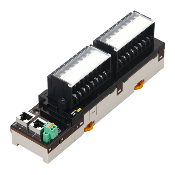
Page 108: 2-Tier Terminal Block Type 16-Point Input Slave Unit Gx-Id1611/Id1621
7 Digital I/O Slave Unit 7-4-1 2-tier Terminal Block Type 16-point Input Slave Unit GX-ID1611/ID1621 Specification Specification Item GX-ID1611 GX-ID1621 Input capacity 16 points Internal I/O common 15 VDC min. (between each input 15 VDC min. (between each input ON voltage... - Page 109 7 Digital I/O Slave Unit Names and functions Terminal arrangement diagram 10 to 18 1 to 9 Name Function Communications connectors Unit power supply connector Refer to "6-3 Specifications of Common Areas" in Page 6 - 4. Status indicators Node Address setting Switches Indicates the state of an input contact (ON/OFF).
- Page 110 7 Digital I/O Slave Unit Internal circuits diagram GX-ID1611 (NPN) CN IN Photocoupler TX− 24 VDC RX− Physical • • layer • • CN OUT Photocoupler • • • • TX− • • • • RX− • • •...
- Page 111 7 Digital I/O Slave Unit Wiring diagram GX-ID1611 (NPN) I/O power supply (24 VDC) NPN output 3-wire sensor 2-wire sensor (Photoelectric sensor, (Limit switch, etc.) proximity sensor) GX-ID1621 (PNP) I/O power supply (24 VDC) PNP output 3-wire sensor...
-
Page 112: 2-Tier Terminal Block Type 16-Point Output Slave Unit Gx-Od1611/Od1621
7 Digital I/O Slave Unit 7-4-2 2-tier Terminal Block Type 16-point Output Slave Unit GX-OD1611/OD1621 Specification Specification Item GX-OD1611 GX-OD1621 Output capacity 16 points Rated current 0.5 A/output, 4.0 A/common (ON current) Internal I/O common 1.2 V max. 1.2 V max. Residual voltage (0.5 ADC, between each output terminal (0.5 ADC, between each output terminal... - Page 113 7 Digital I/O Slave Unit Names and functions Terminal arrangement diagram 10 to 18 1 to 9 Name Function Communications connectors Unit power supply connector Refer to "6-3 Specifications of Common Areas" in Page 6 - 4. Status indicators Node Address setting Switches Indicates the state of an output contact (ON/OFF).
- Page 114 7 Digital I/O Slave Unit Internal circuits diagram GX-OD1611 (NPN) CN IN Photocoupler TX− 24 VDC RX− Physical • • layer • • CN OUT • • • • TX− Photocoupler • • • • RX− • • • •...
- Page 115 7 Digital I/O Slave Unit Wiring diagram GX-OD1611 (NPN) I/O power supply (24 VDC) Solenoid valve, etc. Solenoid valve, etc. GX-OD1621 (PNP) I/O power supply (24 VDC) Solenoid valve, etc. Solenoid valve, etc. Precautions for Correct Use When using an inductive load, such as a solenoid valve, either use a built-in diode for absorbing the counterelectromotive force or install an external diode.
-
Page 116: 2-Tier Terminal Block Relay Type 16-Point Output Slave Unit Gx-Oc1601
7 Digital I/O Slave Unit 7-4-3 2-tier Terminal Block Relay Type 16-point Output Slave Unit GX-OC1601 Specification Item Specification Output capacity 16 points Mounted relays DRTA-NY5W-K Resistance load Rated load 250 VAC 2 A/output, common 8 A 30 VDC 2 A/output, common 8 A Rated ON current 3 A/output Maximum contact voltage... - Page 117 7 Digital I/O Slave Unit Names and functions Terminal arrangement diagram 10 to 18 COM1 1 to 9 COM0 Name Function Communications connectors Unit power supply connector Refer to "6-3 Specifications of Common Areas" in Page 6 - 4. Status indicators Node Address setting Switches Indicates the state of an output contact (ON/OFF).
- Page 118 7 Digital I/O Slave Unit Reference Replacing relays To replace output section relays, first remove the cover using the following procedure. (1) Grab the handle with a finger and bend it upward. (2) The side deflects in the direction of the arrow and the hook is removed. (3) Press down the relay socket lever in the arrow direction using a driver and so on.
- Page 119 7 Digital I/O Slave Unit Internal circuits diagram Photocoupler DRTA-NY5W-K CN IN TX− RX− • Physical • layer • Photocoupler CN OUT • • • • TX− • • COM0 RX− Photocoupler DRTA-NY5W-K UNIT PS DC-DC converter −V (No-isolation • type) •...
-
Page 120: 2-Tier Terminal Block Type 8-Point Input And 8-Point Output Slave Unit Gx-Md1611/Md1621
7 Digital I/O Slave Unit 7-4-4 2-tier Terminal Block Type 8-point Input and 8-point Output Slave Unit GX-MD1611/MD1621 Specification Common to input section and output section Specification Item GX-MD1611 GX-MD1621 Internal I/O common I/O indicators LED display (yellow) Unit power supply current 80 mA max. - Page 121 7 Digital I/O Slave Unit Output section Specification Item GX-MD1611 GX-MD1621 Output capacity 8 points Rated output current 0.5 A/output, 2.0 A/common 1.2 V max. 1.2 V max. Residual voltage (0.5 ADC, between each output terminal (0.5 ADC, between each output terminal and the G terminal) and the V terminal) Leakage current...
- Page 122 7 Digital I/O Slave Unit Names and functions Terminal arrangement diagram Left side (input) Right side (output) 12 to 22 1 to 11 Name Function Communications connectors Unit power supply connector Refer to "6-3 Specifications of Common Areas" in Page 6 - 4. Status indicators Node Address setting Switches Indicates the state of an input contact (ON/OFF).
- Page 123 7 Digital I/O Slave Unit Internal circuits diagram GX-MD1611 (NPN) CN IN Photocoupler 24 VDC TX− RX− • • Photocoupler Physical • • layer • • CN OUT • • TX− Photocoupler 24 VDC RX− • • • • UNIT PS •...
- Page 124 7 Digital I/O Slave Unit Wiring diagram GX-MD1611 (NPN) I/O power supply I/O power supply (24 VDC) (24 VDC) Solenoid valve, etc. Solenoid valve, etc. NPN output 3-wire sensor 2-wire sensor (Photoelectric sensor, (Limit switch, etc.) proximity sensor) GX-MD1621 (PNP) I/O power supply I/O power supply (24 VDC)
- Page 125 7 Digital I/O Slave Unit Precautions for Correct Use • The V1 and V2 terminals as well as the G1 and G2 terminals of the I/O power supply are not connected internally. Supply power separately for V1-G1 and V2-G2. • When using an inductive load, such as a solenoid valve, either use a built-in diode for absorbing the counterelectromotive force or install an external diode.
-
Page 126: 3-Tier Terminal Block Type 16-Point Input Slave Unit Gx-Id1612/Id1622
7 Digital I/O Slave Unit 7-4-5 3-tier Terminal Block Type 16-point Input Slave Unit GX-ID1612/ID1622 Specification Specification Item GX-ID1612 GX-ID1622 Input capacity 16 points Internal I/O common 15 VDC min. (between each input 15 VDC min. (between each input ON voltage terminal and the V terminal) terminal and the G terminal) 5 VDC max. - Page 127 7 Digital I/O Slave Unit Names and functions Terminal arrangement diagram 1 to 9 V1 V1 V1 V1 V1 V1 V1 V1 V2 V2 V2 V2 V2 V2 V2 V2 10 to 18 G1 G1 G1 G1 G1 G1 G1 G1 19 to 27 G2 G2 G2 G2 G2 G2 G2 G2 Name...
- Page 128 7 Digital I/O Slave Unit Internal circuits diagram GX-ID1612 (NPN) CN IN 24 VDC TX− Photocoupler RX− Physical 0 to 7 layer CN OUT Internal • • • • circuits • • TX− 24 VDC RX− Photocoupler 8 to 15 UNIT PS DC-DC converter...
- Page 129 7 Digital I/O Slave Unit Wiring diagram GX-ID1612 (NPN) I/O power supply (24 VDC) 2-wire sensor NPN output 3-wire sensor (Limit switch, etc.) (Photoelectric sensor, proximity sensor) GX-ID1622 (PNP) I/O power supply (24 VDC) 2-wire sensor PNP output 3-wire sensor (Limit switch, etc.) (Photoelectric sensor, proximity sensor)
- Page 130 7 Digital I/O Slave Unit Precautions for Correct Use • The V1 and V2 terminals as well as the G1 and G2 terminals of the I/O power supply are not connected internally. Supply power separately for V1-G1 and V2-G2. • Do not wire NC terminals. Reference Wire colors have been changed according to revisions in the JIS standards for photoelectric and proximity sensors.
-
Page 131: 3-Tier Terminal Block Type 16-Point Output Slave Unit Gx-Od1612/Od1622
7 Digital I/O Slave Unit 7-4-6 3-tier Terminal Block Type 16-point Output Slave Unit GX-OD1612/OD1622 Specification Specification Item GX-OD1612 GX-OD1622 Output capacity 16 points Rated current (ON 0.5 A/output, 4.0 A/common current) Internal I/O common 1.2 V max. 1.2 V max. Residual voltage (0.5 ADC, between each output terminal (0.5 ADC, between each output terminal... - Page 132 7 Digital I/O Slave Unit Names and functions Terminal arrangement diagram 1 to 9 V1 V1 V1 V1 V1 V1 V1 V1 V2 V2 V2 V2 V2 V2 V2 V2 10 to 18 G1 G1 G1 G1 G1 G1 G1 G1 19 to 27 G2 G2 G2 G2 G2 G2 G2 G2 Name...
- Page 133 7 Digital I/O Slave Unit Internal circuits diagram GX-OD1612 (NPN) CN IN 24 VDC TX− RX− Physical Output (0 to 7) layer Photocoupler CN OUT Internal TX− circuits • • • • • • RX− 24 VDC UNIT PS DC-DC converter Output (8 to 15)
- Page 134 7 Digital I/O Slave Unit Wiring diagram GX-OD1612 (NPN) I/O power supply (24 VDC) Solenoid valve, etc. NPN input 3-wire external device (Emitter of photoelectric sensor) GX-OD1622 (PNP) I/O power supply (24 VDC) Solenoid valve, etc. PNP input 3-wire external device (Emitter of photoelectric sensor)
- Page 135 7 Digital I/O Slave Unit Precautions for Correct Use • The V1 and V2 terminals as well as the G1 and G2 terminals of the I/O power supply are not connected internally. Supply power separately for V1-G1 and V2-G2. • Use a maximum current of 500 mA for each V1, V2, G1, and G2 terminals aside from the I/O power supply terminals.
-
Page 136: 3-Tier Terminal Block Type 8-Point Input And 8-Point Output Slave Unit Gx-Md1612/Md1622
7 Digital I/O Slave Unit 7-4-7 3-tier Terminal Block Type 8-point Input and 8-point Output Slave Unit GX-MD1612/MD1622 Specification Common to input section and output section Specification Item GX-MD1612 GX-MD1622 Internal I/O common I/O indicators LED display (yellow) Unit power supply current 90 mA max. - Page 137 7 Digital I/O Slave Unit Output section Specification Item GX-MD1612 GX-MD1622 Output capacity 8 points Rated output current 0.5 A/output, 2.0 A/common 1.2 V max. 1.2 V max. Residual voltage (0.5 ADC, between each output terminal (0.5 ADC, between each output terminal and the G terminal) and the V terminal) Leakage current...
- Page 138 7 Digital I/O Slave Unit Names and functions Terminal arrangement diagram 1 to 9 V1 V1 V1 V1 V1 V1 V1 V1 V2 V2 V2 V2 V2 V2 V2 V2 10 to 18 19 to 27 G1 G1 G1 G1 G1 G1 G1 G1 G2 G2 G2 G2 G2 G2 G2 G2 Name Function...
- Page 139 7 Digital I/O Slave Unit Internal circuits diagram GX-MD1612 (NPN) CN IN 24 VDC TX− Photocoupler RX− Physical 0 to 7 layer CN OUT Internal • • circuits • • TX− • • 24 VDC RX− 0 to 7 UNIT PS DC-DC Photocoupler...
- Page 140 7 Digital I/O Slave Unit Wiring diagram GX-MD1612 (NPN) I/O power supply I/O power (24 VDC) supply (24 VDC) 2-wire sensor NPN output 3-wire Solenoid valve, etc. NPN input 3-wire (Limit switch, etc.) sensor external device (Photoelectric sensor, (Emitter of proximity sensor) photoelectric sensor) ...
- Page 141 7 Digital I/O Slave Unit Precautions for Correct Use • The V1 and V2 terminals as well as the G1 and G2 terminals of the I/O power supply are not connected internally. Supply power separately for V1-G1 and V2-G2. • Use a maximum current of 500 mA for each V1, V2, G1, and G2 terminals aside from the I/O power supply terminals.
-
Page 142: E-Con Connector Type 16-Point Input Slave Unit Gx-Id1618/Id1628
7 Digital I/O Slave Unit 7-4-8 e-CON Connector Type 16-point Input Slave Unit GX-ID1618/ID1628 Specification Specification Item GX-ID1618 GX-ID1628 Input capacity 16 points Internal I/O common 15 VDC min. (between each input 15 VDC min. (between each input ON voltage terminal and the V terminal) terminal and the G terminal) 5 VDC max. - Page 143 7 Digital I/O Slave Unit Names and functions Terminal arrangement diagram GX-ID1618 GX-ID1628 IN10 IN11 IN12 IN13 IN14 IN15 IN10 IN11 IN12 IN13 IN14 IN15 Name Function Communications connectors Unit power supply connector Refer to "6-3 Specifications of Common Areas" in Page 6 - 4. Status indicators Node Address setting Switches Indicates the state of an input contact (ON/OFF).
- Page 144 7 Digital I/O Slave Unit Internal circuits diagram GX-ID1618 (NPN) CN IN TX− Photocoupler RX− Physical Short-circuit protection element layer CN OUT TX− RX− Photocoupler • • Short-circuit • protection element UNIT PS DC-DC converter (No-isolation −V type) GX-ID1628 (PNP) CN IN Short-circuit protection element...
- Page 145 7 Digital I/O Slave Unit Wiring diagram GX-ID1618 (NPN) IN12 IN10 IN11 IN13 IN14 IN15 2-wire sensor NPN output 3-wire sensor (Limit switch, etc.) (Photoelectric sensor, proximity sensor) GX-ID1628 (PNP) IN10 IN11 IN12 IN13 IN14 IN15 2-wire sensor PNP output 3-wire sensor (Limit switch, etc.) (Photoelectric sensor,...
-
Page 146: E-Con Connector Type 16-Point Output Slave Unit Gx-Od1618/Od1628
7 Digital I/O Slave Unit 7-4-9 e-CON Connector Type 16-point Output Slave Unit GX-OD1618/OD1628 Specification Specification Item GX-OD1618 GX-OD1628 Output capacity 16 points Rated current (ON 0.5 A/output, 4.0 A/common current) Internal I/O common 1.2 V max. 1.2 V max. Residual voltage (0.5 ADC, between each output terminal (0.5 ADC, between each output terminal... - Page 147 7 Digital I/O Slave Unit Names and functions Terminal arrangement diagram Name Function Communications connectors Unit power supply connector Refer to "6-3 Specifications of Common Areas" in Page 6 - 4. Status indicators Node Address setting Switches Indicates the state of an output contact (ON/OFF). Output indicators (0 to 15) Not lit: Contact OFF (output OFF state) Lit in yellow: Contact ON (output ON state)
- Page 148 7 Digital I/O Slave Unit Internal circuits diagram GX-OD1618 (NPN) CN IN TX− RX− Photocoupler Physical OUT0 layer CN OUT TX− RX− • • Photocoupler • UNIT PS DC-DC OUT1 converter −V (No-isolation type) • • • GX-OD1628 (PNP) CN IN TX−...
- Page 149 7 Digital I/O Slave Unit Wiring diagram GX-OD1618 (NPN) I/O power supply (24 VDC) Solenoid valve, etc. NPN input 3-wire external device (Emitter of photoelectric sensor) GX-OD1628 (PNP) I/O power supply (24 VDC) Solenoid valve, etc. PNP input 3-wire external device (Emitter of photoelectric sensor) 7 - 51 GX-series EtherCAT Slave Unit User’s Manual...
- Page 150 7 Digital I/O Slave Unit Precautions for Correct Use • The I/O power supply connectors are equipped with two sets of V and G terminals. One set of terminals is used for the I/O power supply for the unit, and the other set is used for the I/O power supply to the next unit.
-
Page 151: E-Con Connector Type 8-Point Input And 8-Point Output Slave Unit
7 Digital I/O Slave Unit 7-4-10 e-CON Connector Type 8-point Input and 8-point Output Slave Unit GX-MD1618/MD1628 Specification Common to input section and output section Specification Item GX-MD1618 GX-MD1628 Internal I/O common I/O indicators LED display (yellow) Unit power supply current 120 mA max. - Page 152 7 Digital I/O Slave Unit Output section Specification Item GX-MD1618 GX-MD1628 Output capacity 8 points Rated output current 0.5 A/output, 2.0 A/common 1.2 V max. 1.2 V max. Residual voltage (0.5 ADC, between each output terminal (0.5 ADC, between each output terminal and the G terminal) and the V terminal) Leakage current...
- Page 153 7 Digital I/O Slave Unit Names and functions Terminal arrangement diagram GX-MD1618 GX-MD1628 Top side: input Bottom side: output Top side: input Bottom side: output ● Name Function Communications connectors Unit power supply connector Refer to "6-3 Specifications of Common Areas" in Page 6 - 4. Status indicators Node Address setting Switches Indicates the state of an input contact (ON/OFF).
- Page 154 7 Digital I/O Slave Unit Internal circuits diagram GX-MD1618 (NPN) CN IN Photocoupler TX− • Short-circuit • • RX− protection element • Physical • • layer CN OUT TX− RX− Photocoupler OUT0 UNIT PS DC-DC converter −V (No-isolation type) ...
- Page 155 7 Digital I/O Slave Unit Wiring diagram GX-MD1618 (NPN) I/O power supply (24 VDC) 2-wire sensor Solenoid valve, etc. NPN output 3-wire NPN input 3-wire (Limit switch, etc.) sensor external device (Photoelectric sensor, (Emitter of proximity sensor) photoelectric sensor) ...
- Page 156 7 Digital I/O Slave Unit Precautions for Correct Use • The I/O power supply connectors are equipped with two sets of V and G terminals. One set of terminals is used for the I/O power supply for the unit, and the other set is used for the I/O power supply to the next unit.
-
Page 157: E-Con Connector Type 32-Point Input Slave Unit Gx-Id3218/Id3228
7 Digital I/O Slave Unit 7-4-11 e-CON Connector Type 32-point Input Slave Unit GX-ID3218/ID3228 Specification Specification Item GX-ID3218 GX-ID3228 Input capacity 32 points Internal I/O common 15 VDC min. (between each input 15 VDC min. (between each input ON voltage terminal and the V terminal) terminal and the G terminal) 5 VDC max. - Page 158 7 Digital I/O Slave Unit Names and functions Terminal arrangement diagram • GX-ID3218 IN12 IN12 IN10 IN11 IN13 IN14 IN15 IN10 IN11 IN13 IN14 IN15 • GX-ID3228 IN12 IN10 IN11 IN13 IN14 IN15 IN10 IN11 IN12 IN13 IN14 IN15 7 - 60 GX-series EtherCAT Slave Unit User’s Manual...
- Page 159 7 Digital I/O Slave Unit Name Function Communications connectors Unit power supply connector Refer to "6-3 Specifications of Common Areas" in Page 6 - 4. Status indicators Node Address setting Switches Indicates the state of an input contact (ON/OFF). Input indicators Not lit: Contact OFF (input OFF state) (IN1 0 to 15, IN2 0 to 15) Lit in yellow: Contact ON (input ON state)
- Page 160 7 Digital I/O Slave Unit Internal circuits diagram GX-ID3218 (NPN) CN IN TX− Photocoupler RX− Physical Short-circuit protection element layer CN OUT TX− RX− Photocoupler • • Short-circuit • protection element UNIT PS DC-DC converter (No-isolation −V type) GX-ID3228 (PNP) CN IN Short-circuit protection element...
- Page 161 7 Digital I/O Slave Unit Wiring diagram GX-ID3218 (NPN) IN12 IN12 IN10 IN11 IN13 IN14 IN15 IN10 IN11 IN13 IN14 IN15 2-wire sensor NPN output 3-wire sensor (Limit switch, etc.) (Photoelectric sensor, proximity sensor) GX-ID3228 (PNP) IN10 IN11 IN12 IN13 IN14...
-
Page 162: E-Con Connector Type 32-Point Output Slave Unit Gx-Od3218/Od3228
7 Digital I/O Slave Unit 7-4-12 e-CON Connector Type 32-point Output Slave Unit GX-OD3218/OD3228 Specification Specification Item GX-OD3218 GX-OD3228 Output capacity 32 points Rated current (ON 0.5 A/output, 4.0 A/common current) Internal I/O common 1.2 V max. 1.2 V max. Residual voltage (0.5 ADC, between each output terminal (0.5 ADC, between each output terminal... - Page 163 7 Digital I/O Slave Unit Names and functions Terminal arrangement diagram OUT1 OUT2 Name Function Communications connectors Unit power supply connector Refer to "6-3 Specifications of Common Areas" in Page 6 - 4. Status indicators Node Address setting Switches Indicates the state of an output contact (ON/OFF).
- Page 164 7 Digital I/O Slave Unit Internal circuits diagram GX-OD3218 (NPN) CN IN Left side TX− Photocoupler OUT0 RX− • • • Physical layer CN OUT • • • TX− RX− UNIT PS DC-DC converter Right side (No-isolation Photocoupler −V type) OUT0 •...
- Page 165 7 Digital I/O Slave Unit Wiring diagram GX-OD3218 (NPN) I/O power supply (24 VDC) Solenoid valve, etc. NPN input 3-wire external device (Emitter of photoelectric sensor) GX-OD3228 (PNP) I/O power supply (24 VDC) Solenoid valve, etc. PNP input 3-wire external device (Emitter of photoelectric sensor) 7 - 67 GX-series EtherCAT Slave Unit User’s Manual...
- Page 166 7 Digital I/O Slave Unit Precautions for Correct Use • The I/O power supply connectors on the left and right are equipped with two sets of V and G terminals. One set of terminals is used for the I/O power supply for the unit, and the other set is used for the I/O power supply to the next unit.
-
Page 167: Gx-Md3218/Md3228
7 Digital I/O Slave Unit 7-4-13 e-CON Connector Type 16-point Input and 16-point Output Slave Unit GX-MD3218/MD3228 Specification Common to input section and output section Specification Item GX-MD3218 GX-MD3228 Internal I/O common I/O indicators LED display (yellow) Unit power supply current 150 mA max. - Page 168 7 Digital I/O Slave Unit Output section Specification Item GX-MD3218 GX-MD3228 Output capacity 16 points Rated output current 0.5 A/output, 2.0 A/common 1.2 V max. 1.2 V max. Residual voltage (0.5 ADC, between each output terminal (0.5 ADC, between each output terminal and the G terminal) and the V terminal) Leakage current...
- Page 169 7 Digital I/O Slave Unit Names and functions Terminal arrangement diagram Right side (output) Left side (input) IN12 IN10 IN11 IN13 IN14 IN15 Name Function Communications connectors Unit power supply connector Refer to "6-3 Specifications of Common Areas" in Page 6 - 4. Status indicators Node Address setting Switches Indicates the state of an input contact (ON/OFF).
- Page 170 7 Digital I/O Slave Unit Internal circuits diagram GX-MD3218 (NPN) CN IN Left side TX− Photocoupler RX− Short-circuit protection element Physical layer CN OUT • • TX− • RX− • • • Photocoupler OUT0 Right side UNIT PS DC-DC converter (No-isolation −V...
- Page 171 7 Digital I/O Slave Unit Wiring diagram GX-MD3218 (NPN) IN10 IN11 IN12 IN13 IN14 IN15 I/O power supply (24 VDC) Solenoid valve, etc. NPN input 3-wire 2-wire sensor NPN output 3-wire external device (Limit switch, etc.) sensor (Emitter of photoelectric sensor) (Photoelectric sensor, proximity sensor) ...
- Page 172 7 Digital I/O Slave Unit Precautions for Correct Use • The I/O power supply connectors are equipped with two sets of V and G terminals. One set of terminals is used for the I/O power supply for the unit, and the other set is used for the I/O power supply to the next unit.
-
Page 173: Mounting Dimensions
7 Digital I/O Slave Unit Mounting Dimensions The mounting dimensions of a Digital I/O Slave Unit are shown below. 7-5-1 2-tier Terminal Block Type GX-ID1611/ID1621/OD1611/OD1621 (mm) GX-OC1601 (mm) 7 - 75 GX-series EtherCAT Slave Unit User’s Manual... -
Page 174: 3-Tier Terminal Block Type
7 Digital I/O Slave Unit GX-MD1611/MD1621 (mm) 7-5-2 3-tier Terminal Block Type 10.1 (mm) 7 - 76 GX-series EtherCAT Slave Unit User’s Manual... -
Page 175: E-Con Connector Type
7 Digital I/O Slave Unit 7-5-3 e-CON Connector Type GX-ID1618/ID1628 (mm) GX-OD1618/OD1628/MD1618/MD1628 (mm) 7 - 77 GX-series EtherCAT Slave Unit User’s Manual... - Page 176 7 Digital I/O Slave Unit GX-ID3218/ID3228 (mm) GX-OD3218/OD3228 (mm) 7 - 78 GX-series EtherCAT Slave Unit User’s Manual...
- Page 177 7 Digital I/O Slave Unit GX-MD3218/MD3228 (mm) 7 - 79 GX-series EtherCAT Slave Unit User’s Manual...
- Page 178 7 Digital I/O Slave Unit 7 - 80 GX-series EtherCAT Slave Unit User’s Manual...
-
Page 179: Analog I/O Slave Unit
Analog I/O Slave Unit This chapter explains the overview of the Analog I/O Slave Unit. 8-1 Analog I/O Slave Unit ......... . . 8-2 8-2 Overview of the Analog Input Slave Unit . -
Page 180: Analog I/O Slave Unit
8 Analog I/O Slave Unit Analog I/O Slave Unit Analog I/O Slave Units refer to slaves with processing functions for analog I/O data (voltage value/current value). Other functions of the Slave Unit include the Moving Average and User Adjustment. 8 - 2 GX-series EtherCAT Slave Unit User’s Manual... -
Page 181: Overview Of The Analog Input Slave Unit
8 Analog I/O Slave Unit Overview of the Analog Input Slave Unit Analog Input Slave Unit convert (AD conversion) analog input signals such as 1 to 5 V and 4 to 20 mA to digital data (binary values) and store them in the EtherCAT Master Unit. 8-2-1 Input Range and Converted Data Input analog signals are converted to digital data in the following manner using a set input range. - Page 182 8 Analog I/O Slave Unit Input range 1 to 5 V Voltage of 1 to 5 V is converted to data from 0000 to 1F40 hex (0 to 8000). The input data range for which conversion is possible is 0.8 to 5.2 V and here the output data is FE70 to 20D0 hex (−400 to +8400).
- Page 183 8 Analog I/O Slave Unit Input range −10 to +10 V Voltage of −10 to +10 V is converted to data from F060 to 0F40 hex (−4000 to +4000). The input data range for which conversion is possible is −11 to +11 V and here the output data is EED0 to 1130 hex (−4400 to +4400).
-
Page 184: I/O Data Allocation (Pdo Mapping)
8 Analog I/O Slave Unit 8-2-2 I/O Data Allocation (PDO Mapping) An Analog Input Slave Unit has input data for four channels and Sysmac error status. It is allocated to the IN area of I/O memory of the EtherCAT Master Unit. Refer to the manual of the EtherCAT Master Unit for allocation methods. -
Page 185: Function Of The Analog Input Slave Unit
8 Analog I/O Slave Unit Function of the Analog Input Slave Unit An Analog Input Slave Units has the following convenient functions, in addition to the I/O signal processing. 8-3-1 AD Conversion Available Point Setting Overview of functions Purpose This function sets to skip processing unused points, and enhances the speed of refresh cycles of analog input. -
Page 186: Moving Average
8 Analog I/O Slave Unit 8-3-2 Moving Average Overview of functions Purpose The function averages the inputs if they fluctuates minutely due to noise and so on as shown in the figure below, and obtains smooth input values. Analog input value Actual input Input after averaging processing... - Page 187 8 Analog I/O Slave Unit Analog conversion time (number of AD conversion available points × 500 μs) Actual analog conversion data Time [ms] Initial Initial Initial Initial Moving average Moving average value = (D1 × 4) /4 data data data data calculation (Initial) Moving average...
-
Page 188: Disconnected Line Detection
8 Analog I/O Slave Unit 8-3-3 Disconnected Line Detection Overview of functions Purpose The function detects a disconnection of analog input signal line. Note that this function is valid only when the input range is "1 to 5 V" or "4 to 20 mA." ... - Page 189 8 Analog I/O Slave Unit Converted data After correction Before correction 100% Voltage/current The correctable range is from −5% to +5% each of the minimum and maximum input values. The correctable range for each input range is as follows. Input range Low limit High limit −0.25 to +0.25 V...
-
Page 190: Overview Of The Analog Output Slave Unit
8 Analog I/O Slave Unit Overview of the Analog Output Slave Unit An Analog Output Slave Unit converts (DA conversion) digital data (binary value) stored in the EtherCAT Master Unit to analog signals such as 1 to 5 V and 4 to 20 mA and output them. 8-4-1 Output Range and Converted Data Digital data that is output is converted to analog data using a set output range as shown below. - Page 191 8 Analog I/O Slave Unit Output range 0 to 10 V Data from 0000 to 1F40 hex (0 to 8000) is converted to voltage from 0 to 10 V and output. The output data range for which conversion is possible is FE70 to 20D0 hex (−400 to +8400) and here the output data is −0.5 to +10.5 V.
-
Page 192: I/O Data Allocation (Pdo Mapping)
8 Analog I/O Slave Unit Output range setting The output range is set using the output range setting switch (DIP switch) of a Slave Unit or by SDO communications. When SDO communication is used for the setting, the target index is 3201 hex. For the set value, refer to the corresponding index of "Appendix A-1 Object Dictionary"... -
Page 193: Function Of The Analog Output Slave Unit
8 Analog I/O Slave Unit Function of the Analog Output Slave Unit An Analog Output Slave Unit has the following convenient functions, in addition to the output signal processing. 8-5-1 DA Conversion Available Point Setting Overview of functions Purpose This function sets to skip processing unused points, and enhances the speed of refresh cycles of analog output. -
Page 194: Analog Output Fault Action
8 Analog I/O Slave Unit 8-5-2 Analog Output Fault Action Overview of functions Purpose This function outputs set values if a communications error occurs. Details of functions It is possible to set a value to be output when a communications error occurs for each point. Select an output value from the following 5 patterns. -
Page 195: User Adjustment
8 Analog I/O Slave Unit 8-5-3 User Adjustment Overview of functions Purpose If final output voltage and current deviates due to characteristics of output devices and methods of connection, correct the "deviation" and adjust outputs. Details of functions This function corrects conversion values of output voltages and currents at 2 points, 0% and 100%, as shown in the figure below. -
Page 196: Overview Of Each Slave Unit Type
8 Analog I/O Slave Unit Overview of Each Slave Unit Type This section shows the specification of Analog I/O Slave Units, names and functions of each part, internal circuit diagram, and wiring diagram. Refer to the following corresponding page to each model. Reference page Internal Type... -
Page 197: 4-Point Input Slave Unit Gx-Ad0471
8 Analog I/O Slave Unit 8-6-1 4-point Input Slave Unit GX-AD0471 Specification Specification Item Voltage input Current input Input capacity 4 points (possible to set number of enabled points) 0 to 5 V 1 to 5 V Input range 4 to 20 mA 0 to 10 V −10 to +10 V Input range setting... - Page 198 8 Analog I/O Slave Unit Names and functions Terminal arrangement diagram − − − − Name Function Communications connectors Unit power supply connector Refer to "Specifications of Common Areas" in Page 6 - 4. Status indicators Node Address setting Switches Input range setting Switches DIP switches for setting input range (Refer to the following section.) Terminal block for analog input signals...
- Page 199 8 Analog I/O Slave Unit • Input range setting switches Set input range by combination of individual DIP switches. To enable settings of these switches, it is necessary to turn Pin8 (input range setting method) ON in advance. Pin No. Setting Specification Setting of input CH1/CH2 range (common)
- Page 200 8 Analog I/O Slave Unit Internal circuits diagram 510 kΩ 250 Ω V− 510 kΩ Analog GND Wiring diagram Short-circuit * V1+ I1+ V2+ I2+ V3+ I3+ V4+ I4+ V4− NC V1− AG V2− AG V3− AG Voltage input Current input Short-circuit the “V positive”...
-
Page 201: 2-Point Output Slave Unit Gx-Da0271
8 Analog I/O Slave Unit 8-6-2 2-point Output Slave Unit GX-DA0271 Specification Specification Item Voltage output Current output Output capacity 2 points (possible to set number of enabled points) 0 to 5 V 1 to 5 V Output range 4 to 20 mA 0 to 10 V −10 to +10 V Output range setting... - Page 202 8 Analog I/O Slave Unit Terminal arrangement diagram − − Name Function Communications connectors Unit power supply connector Refer to "Specifications of Common Areas" in Page 6 - 4. Status indicators Node Address setting Switches DIP switches for setting output range (Refer to the following Output range setting Switches section.) Terminal block for analog output signals...
- Page 203 8 Analog I/O Slave Unit • Setting of output CH1 range (Pin1 to Pin3) Output range Pin1 Pin2 Pin3 0 to 5 V 1 to 5 V 0 to 10 V −10 to +10 V 4 to 20 mA • Setting of output CH2 range (Pin4 to Pin6) Output range Pin4 Pin5...
- Page 204 8 Analog I/O Slave Unit Wiring diagram V1+ I1+ V2+ I2+ 1− 2− Output 1: At voltage output Output 2: At current output External device External device Precautions for Correct Use Do not wire NC terminals. 8 - 26 GX-series EtherCAT Slave Unit User’s Manual...
-
Page 205: Mounting Dimensions
8 Analog I/O Slave Unit Mounting Dimensions The mounting dimensions of an Analog I/O Slave Unit are shown below. (mm) 8 - 27 GX-series EtherCAT Slave Unit User’s Manual... - Page 206 8 Analog I/O Slave Unit 8 - 28 GX-series EtherCAT Slave Unit User’s Manual...
- Page 207 Encoder Input Slave Unit This chapter explains the overview of Encoder Input Slave Unit. 9-1 Encoder Input Slave Unit ........9-2 9-2 I/O Data Allocation .
-
Page 208: Encoder Input Slave Unit
9 Encoder Input Slave Unit Encoder Input Slave Unit An Encoder Input Slave Unit has 5 V and 24 V open collector input function or line driver input function. The open collector input can be measured up to 500 kHz and the line driver input up to 4 MHz. 9 - 2 GX-series EtherCAT Slave Unit User’s Manual... -
Page 209: I/O Data Allocation
9 Encoder Input Slave Unit I/O Data Allocation I/O data of Encoder Input Slave Units are allocated to the input/output areas of the I/O memory of the EtherCAT Master Unit, respectively. Also, the Sysmac error status is allocated to the IN area of I/O memory of the EtherCAT Master Unit. The ESI file are used to allocate I/O data. - Page 210 9 Encoder Input Slave Unit The data allocation is as follows when using the default settings. Counter status + counter present value data + external latch A data + external latch B data (size = 26 bytes) Offset (byte) CRUN1 CERR1 Reserved...
- Page 211 9 Encoder Input Slave Unit Counter status + counter present value data + external latch A data + external latch B data + Sysmac error status (size = 27 bytes) Offset (byte) CRUN1 CERR1 Reserved EXLB1 EXLA1 EXRES1 RACK1 PACK1 CRUN2 CERR2...
-
Page 212: Output Data Allocation
9 Encoder Input Slave Unit Abbreviations used for the counter status information description have the following meanings. Abbreviation Status name Operation Soft switch "Present value preset execution" completion flag Present value preset PACKn 0→1: Preset execution completed execution completed 1→0: Soft switch "Present value preset execution" is set to 0 Soft switch "Present value internal reset execution"... - Page 213 9 Encoder Input Slave Unit The data allocation is as follows when using the default settings. Soft switch + preset command value (size = 12 bytes) Offset (byte) Reserved Reserved Reserved Reserved Reserved INPRES1 PSET1 CENB1 Reserved EXLBC1 EXLAC1 EXRESC1 Reserved EXLBE1...
-
Page 214: Function Of The Encoder Input Slave Units
9 Encoder Input Slave Unit Function of the Encoder Input Slave Units This section explains the function of Encoder Input Slave Units. 9-3-1 Count Mode The Count Mode is run by the Circular Counter. 9-3-2 Circular Counter Set the maximum Circular Counter value and perform incremental/decremental count in the range from 0 to the maximum value or from the maximum value to 0. -
Page 215: Input Signal Types
9 Encoder Input Slave Unit Precautions for Safe Use • If you change the maximum Circular Counter value when the counter is stopped or operating, restart the counter to enable using the new maximum value in counter operation. • If the set value is read without restarting, the set value after change can be read, but the actual count operation is performed with the set value before change. - Page 216 9 Encoder Input Slave Unit When phase A/B phase difference pulse is input, the connection with external input devices becomes as follows. Encoder Input Slave Unit Input A Input B Encoder Input Z (Reset Input) Code + pulse input Input A is count pulse signal and input B is count direction control signal.
-
Page 217: Encoder Direction Setting
9 Encoder Input Slave Unit When incremental/decremental pulses are input, the connection with external input devices becomes as follows. Encoder Input Slave Unit Encoder or other Input A pulse generators Incremental pulse Input B Encoder or other Input Z pulse generators Decremental pulse Precautions for Safe Use... -
Page 218: Counter Reset
9 Encoder Input Slave Unit 9-3-5 Counter Reset It is possible to reset counter value for each channel using the elements shown below. Counter reset bit The counter of each channel is reset to 0 by changing soft switch "present value internal reset execution"... -
Page 219: Counter Preset
9 Encoder Input Slave Unit 9-3-6 Counter Preset It is possible to preset counter value for each channel using the elements shown below. Counter preset bit The counter present value is overwritten by "preset command value" by changing soft switch "present value preset execution"... -
Page 220: Specifications For Each Slave Unit
9 Encoder Input Slave Unit Specifications for Each Slave Unit This section shows the specification of Encoder Input Slave Units, names and functions of each part, internal circuit diagram, and wiring diagram. Refer to the following corresponding page to each model. Reference page Internal Type... -
Page 221: Open Collector Input Type Gx-Ec0211
9 Encoder Input Slave Unit 9-4-1 Open collector input type GX-EC0211 Specification Slave Unit specifications Item Specification Counter point 2 points Counter phase A Counter phase B Input signal Counter phase Z Latch input (A/B) Counter reset input Counter enabled status LED display (green) display Input indicators... - Page 222 9 Encoder Input Slave Unit Pulse input timing specifications Counter input phase Z Counter input phase A/B Input pulse duty: 50% voltage Terminal Terminal input input voltage voltage Relationship between phase A and phase B at phase difference pulse input voltage Phase A voltage...
- Page 223 9 Encoder Input Slave Unit Latch/reset input specifications Specification Item Latch input (A/B) Reset input Internal I/O common 20.4 to 26.4 VDC (24 VDC −15 to +10%) 20.4 to 26.4 VDC (24 VDC −15 to +10%) Input voltage Input impedance 4.0 kΩ...
- Page 224 9 Encoder Input Slave Unit • Input indicators Name State Contents Name State Contents Lit green. Counter operating Lit green. Counter operating Counter stopped Counter stopped Input A (phase A signal/count Input A (phase A signal/count pulse signal/incremental count pulse signal/incremental count yellow.
- Page 225 9 Encoder Input Slave Unit • Terminal block Terminal block Terminal name Contents number Encoder power supply input (power supply input at twisted-pair wiring) Encoder power supply input (power supply input at twisted-pair wiring) Encoder power supply input (power supply input at twisted-pair wiring) LA1/LA2 Latch A input...
- Page 226 9 Encoder Input Slave Unit Internal circuits diagram CN IN TX− Photocoupler RX− Physical layer 1.2 kΩ 1.5 kΩ CN OUT TX− 430 Ω RX− Photocoupler UNIT PS 1.2 kΩ 1.5 kΩ DC-DC converter (No-isolation 430 Ω −V type) Photocoupler 1.2 kΩ...
- Page 227 9 Encoder Input Slave Unit Wiring diagram Sensor power supply (24 VDC) RSV RSV V1 RSV LA2 LB2 RST2 RSV RSV V1 RSV LA1 LB1 RST1 A24 B24 Z24 A24 B24 Z24 White: White: Phase B Phase B Black: Black: Phase A Phase A Orange:...
- Page 228 9 Encoder Input Slave Unit Sensor power supply (24 VDC) RSV RSV V1 RSV LA1 LB1 RST1 RSV RSV V1 RSV LA2 LB2 RST2 A24 B24 Z24 A24 B24 Z24 Black: Phase A Reset Latch Phase Phase Phase White: Phase B Reset Latch Orange: Phase Z...
-
Page 229: Line Driver Input Type Gx-Ec0241
9 Encoder Input Slave Unit 9-4-2 Line Driver Input Type GX-EC0241 Specification Slave Unit specifications Item Specification Counter point 2 points Counter phase A Counter phase B Input signal Counter phase Z Latch input (A/B) Counter reset input Counter enabled status LED display (green) display Input indicators... - Page 230 9 Encoder Input Slave Unit Pulse input timing specifications Counter input phase A/B Counter input phase Z Input pulse duty: 50% voltage voltage A/B (+) Z (+) voltage Terminal Terminal input input A/B (−) Z (−) voltage Relationship between phase A and phase B at phase difference pulse input voltage A (+) voltage...
- Page 231 9 Encoder Input Slave Unit Latch/reset input specifications Specification Item Latch input (A/B) Reset input Internal I/O common 20.4 to 26.4 VDC (24 VDC −15 to +10%) 20.4 to 26.4 VDC (24 VDC −15 to +10%) Input voltage Input impedance 4.0 kΩ...
- Page 232 9 Encoder Input Slave Unit • Input indicators Name State Contents Name State Contents Lit green. Counter operating Lit green. Counter operating Counter stopped Counter stopped Input A (phase A signal/count Input A (phase A signal/count pulse signal/incremental count pulse signal/incremental count yellow.
- Page 233 9 Encoder Input Slave Unit • Terminal block Terminal block Terminal name Contents number LA1/LA2 Latch A input LB1/LB2 Latch B input RST1/RST2 Reset input Internal circuit/sensor power supply input (Spare) Phase A input (+) Phase B input (+) Phase Z input (+) (Spare) Sensor power supply output Sensor power supply output...
- Page 234 9 Encoder Input Slave Unit Internal circuits diagram CN IN DC-DC TX− converter (No-isolation RX− Line type) receiver Physical layer A− CN OUT 4.7 kΩ TX− 4.7 kΩ RX− B− 4.7 kΩ 4.7 kΩ UNIT PS DC-DC Z− converter 4.7 kΩ (No-isolation −V type)
- Page 235 9 Encoder Input Slave Unit Wiring diagram Internal circuit / sensor power supply (24 VDC) RSV RSV RSV RSV RSV RSV LA2 LB2 RST2 RSV RSV RSV RSV RSV RSV LA1 LB1 RST1 A − B − Z − A − B −...
-
Page 236: Mounting Dimensions
9 Encoder Input Slave Unit Mounting Dimensions The mounting dimensions of an Encoder Input Slave Unit are shown below. 10.1 [mm] 9 - 30 GX-series EtherCAT Slave Unit User’s Manual... -
Page 237: Io-Link Master Unit
IO-Link Master Unit 10-1 What Is an IO-Link Master Unit? ....... . . 10-2 10-1-1 Introduction . -
Page 238: What Is An Io-Link Master Unit
10 IO-Link Master Unit 10-1 What Is an IO-Link Master Unit? 10-1-1 Introduction An IO-Link Master Unit is a slave that has I/O processing functions for IO-Link communications with IO-Link devices and I/O processing functions for digital I/O data (ON/OFF signals) with non-IO_Link devices. -
Page 239: Support Software To Be Used
10 IO-Link Master Unit 10-1-3 Support Software to Be Used The following support software tools are used for IO-Link Systems. Application Controller I/O allocation setting PDO assignment IO-Link master Settings/monitor for for controller setting setting I/O-Link device NJ/NX-series Sysmac Studio Sysmac Studio Sysmac Studio CX-ConfiguratorFDT... -
Page 240: I/O Data Allocations: Pdo Mapping
10 IO-Link Master Unit 10-2 I/O Data Allocations: PDO Mapping The data in the IO-Link Master Unit is allocated in the OUT and IN areas in the I/O memory of the EtherCAT Master Unit. Also, the Sysmac error status is allocated to the IN area of I/O memory of the EtherCAT Master Unit. Refer to the manual of the EtherCAT Master Unit for allocation methods. - Page 241 10 IO-Link Master Unit The following data is allocated for the default settings. • Unit version 1.0 Input offset (words) D15: I/O Power On/Off Status, Input Data Enabled Flags D14: IO-Link Communications Module Processing Error, D08 to D13: Not used. Error Status for I/O Port 2 Error Status for I/O Port 1 Error Status for I/O Port 4...
-
Page 242: Allocating Output Data
10 IO-Link Master Unit 10-2-2 Allocating Output Data The IO-Link Master Unit has the following types of output data. You can allocate the required data in the OUT area. Default I/O Data name Size Details allocation Digital Output Data 2 bytes This is the digital output data in SIO(DO) Mode. -
Page 243: Functions Of The Io-Link Master Unit
10 IO-Link Master Unit 10-3 Functions of the IO-Link Master Unit This section provides an overview of the functions of the IO-Link Master Unit. For details, refer to the IO-Link System User’s Manual (W570). Function name Description I/O data (process data) in the IO-Link devices is cyclically exchanged with the IO-Link Master Unit as the IO-Link communications master. - Page 244 10 IO-Link Master Unit Function name Description This function turns OFF outputs from the IO-Link Master Unit when an error occurs in communications with the controller in IO-Link Mode or in Load rejection for controller an SIO mode. communications error This prevents output operations with incorrect values when a communications error occurs.
-
Page 245: Specifications
10 IO-Link Master Unit 10-4 Specifications This section gives the specifications and part names of the IO-Link Master Unit, describes its functions, and provides wiring diagrams. 10-4-1 Specifications Communications Specifications The following table gives the EtherCAT communications specifications of the GX-ILM08C. Refer to "6-1 EtherCAT Communications Specifications"... - Page 246 10 IO-Link Master Unit General Specifications The following table gives the general specifications of the GX-ILM08C. Item Specification Unit power supply 20.4 to 26.4 VDC (24 VDC −15%/+10%) voltage 20.4 to 26.4 VDC (24 VDC −15%/+10%) I/O power supply Noise resistance Conforms to IEC 61000-4-4, 2 kV (power line).
- Page 247 10 IO-Link Master Unit Unit Specifications The specifications for the GX-ILM08C are given below. Item Specification Unit name IO-Link Master Unit Model GX-ILM08C Number of IO-Link ports COM1: 4.8 kbps Communications Baud rate COM2: 38.4 kbps specifications COM3: 230.4 kbps Rated voltage 24 VDC (20.4 to 26.4 VDC) Device power...
- Page 248 10 IO-Link Master Unit Item Specification IN communications Internal connector Isolation circuits circuit OUT communications connector connector IO-Link Non- circuits Unit power supply isolated 24 V power Circuit layout supply Unit power supply circuits connector Power supply connector I/O power Non-isolated supply 24 V power supply...
-
Page 249: Part Names And Functions
10 IO-Link Master Unit 10-4-2 Part Names and Functions Name Function EtherCAT communications EtherCAT cable connection: IN side connector, IN M12 connector (D-coding, female) EtherCAT communications EtherCAT cable connection: OUT side connector, OUT M12 connector (D-coding, female) Connects to Unit power supply and I/O power supply cable. Power supply connector M12 connector (A-coding, male) Connect to IO-Link sensor cables (IO-Link connector type: Class... - Page 250 10 IO-Link Master Unit Status Indicators L/A IN Indicator This indicator shows the input communications status. For the indicator specifications, refer to "6-3-1 Status Indicators" in Page 6 - 4. L/A OUT Indicator This indicator shows the output communications status. For the indicator specifications, refer to "6-3-1 Status Indicators"...
- Page 251 10 IO-Link Master Unit I/O Indicators C/E Indicator These indicator show the IO-Link communications status and error status. Label Color Status Meaning IO-Link communications are in progress during operation in Lit. IO-Link Mode. • IO-Link communications are stopped during operation in Green IO-Link Mode.
- Page 252 10 IO-Link Master Unit I/O Connectors Port 1 Port 2 Port 3 Port 4 Port 5 Port 6 Port 7 Port 8 Power Supply Connector Signal Description UNT_P+ Unit power supply + Unit power supply − UNT_P− I/O_P+ I/O power supply + I/O power supply −...
-
Page 253: Mounting Dimensions
10 IO-Link Master Unit 10-5 Mounting Dimensions The mounting dimensions of the IO-Link Master Unit are shown below. GX-ILM08C 49.1 44.9 Two, M5 40.7 or 5.3-dia. holes 15.1 24.8 13.5 32.8 Mounting dimensions 46.5 35.15 (mm) 10 - 17 GX-series EtherCAT Slave Unit User’s Manual... -
Page 254: Communications Performance
10 IO-Link Master Unit 10-6 Communications Performance This section describes the I/O response times of the GX-series IO-Link Master Unit. The I/O response time is the time required for the following processing: The CPU Unit processes an external signal input to one EtherCAT slave, and another EtherCAT (CoE) slave outputs the processed result as an external signal. - Page 255 10 IO-Link Master Unit Output Data I/O data type IO-Link process output data from IO-Link Digital output data in SIO (DO) Mode communications in IO-Link Mode Parameter × 0.091 × Pout_size + 0.001 (Total size (in 0.091 × Pout_size + 0.001 ×...
-
Page 256: Determining The Io-Link Communications Cycle
10 IO-Link Master Unit 10-6-2 Determining the IO-Link Communications Cycle The IO-Link communications cycle depends on the baud rate of the IO-Link devices, as described below. Refer to the instruction manuals for individual IO-Link devices for the IO-Link device baud rates. When the IO-Link Device Baud Rate Is COM3 (230.4 kbps) The IO-Link communications cycle depends on whether the minimum cycle time of the IO-Link devices is less than or equal to 1.1 ms or greater than 1.1 ms, as described below. -
Page 257: Connected Device Specifications And Models
10 IO-Link Master Unit 10-7 Connected Device Specifications and Models EtherCAT Cables Cables to Connect a GX-type IO-Link Master Unit to a Master or Slave with an RJ45 Connector Num- Avail- Cable ber of Specifica- able connec- Cable Name and appearance cable Model tion... - Page 258 10 IO-Link Master Unit Power Supply Cables for GX-type IO-Link Master Units Number Avail- Cable of cable able connec- Specifica- Cable Name and appearance Model tion conduc- connec- tion length tors tors direction Smart- Straight XS5F-D421-C80-F XS5F Connector with Cable, M12 socket Socket on One End on one end...
- Page 259 10 IO-Link Master Unit Extension Cables from Sensors with M12 Plugs Num- Avail- ber of Cable con- Specifica- able Cable Name and appearance cable nection Model tion connec- length con- direction tors ductors XS5W Connector with Cable M12 socket Smart- Straight/ XS5W-D421-C81-F...
- Page 260 10 IO-Link Master Unit Name and appearance Specification Connector type Materials Model XS5Z-11 Smartclick Waterproof Cover Smartclick con- nector *1 When mounting the M12 Threaded Waterproof Cover on a connector, always tighten it to a torque of 0.39 to 0.49 N·m. *2 When mounting a Smartclick Waterproof Cover on a connector, torque management is not required.
-
Page 261: Expansion Unit
Expansion Unit This chapter overviews the Expansion Unit. 11-1 Overview of the Expansion Unit ....... . . 11-2 11-1-1 Connecting Expansion Units . -
Page 262: Overview Of The Expansion Unit
11 Expansion Unit 11-1 Overview of the Expansion Unit One Expansion Unit can be added to a Digital I/O Slave Unit (GX-ID 1611/ID1621/ OD1611/OD1621/OC1601) (2-tier terminal block type16-point Slave Unit) The use of Expansion Units enables flexible I/O capacity expansion. This section explains how to connect the Expansion Unit and supply the unit power. -
Page 263: I/O Power Supply
Expansion Unit Input Output XWT-ID08(-1) XWT-ID16(-1) XWT-OD08(-1) XWT-OD16(-1) Slave Unit GX-ID1611 Power is supplied only to the Slave Unit. Power is supplied to both the Slave Unit Input Power supply to the Expansion Unit is not and Expansion Unit. GX-ID1621 required. -
Page 264: Specifications Of Expansion Unit
11 Expansion Unit 11-2 Specifications of Expansion Unit The chart below shows the Expansion Unit specifications, component names and functions, internal circuits and wiring diagram. Refer to the following corresponding page to each model. Reference page Internal Model Names and Wiring Specification circuits... -
Page 265: Point Input Expansion Unit Xwt-Id08/Id08-1
11 Expansion Unit 11-2-1 8-point Input Expansion Unit XWT-ID08/ID08-1 Specification Specification Item XWT-ID08 XWT-ID08-1 Internal I/O common I/O capacity 8 inputs 15 VDC min. (between each input 15 VDC min. (between each input ON voltage terminal and the V terminal) terminal and the G terminal) 5 VDC max. - Page 266 11 Expansion Unit Name Function Indicates the state of each input contact (ON/OFF). Input indicators (0 to 7) Not lit: Contact OFF (input OFF state) Lit in yellow: Contact ON (input ON state) Slave connector Connects the connector on the right side of the Slave Unit. Connects external devices and the I/O power supply.
- Page 267 11 Expansion Unit Wiring diagram XWT-ID08 (NPN) I/O power supply (24 VDC) NPN output 3-wire 2-wire sensor sensor (Limit switch, etc.) (Photoelectric sensor, proximity sensor) XWT-ID08-1 (PNP) I/O power supply PNP output 3-wire 2-wire sensor sensor (Limit switch, etc.) (Photoelectric sensor, proximity sensor) Reference...
-
Page 268: Point Output Expansion Unit Xwt-Od08/Od08-1
11 Expansion Unit 11-2-2 8-point Output Expansion Unit XWT-OD08/OD08-1 Specification Specification Item XWT-OD08 XWT-OD08-1 Internal I/O common I/O capacity 8 outputs Rated output current 0.5 A/output, 2.0 A/common 1.2 V max. 1.2 V max. Residual voltage (0.5 ADC, between each output terminal (0.5 ADC, between each output terminal and the G terminal) and the V terminal) - Page 269 11 Expansion Unit Name Function Indicates the state of each output contact (ON/OFF). Output indicators (0 to 7) Not lit: Contact OFF (output OFF state) Lit in yellow: Contact ON (output ON state) Slave connector Connects the connector on the right side of the Slave Unit. Connects external devices and the I/O power supply.
- Page 270 11 Expansion Unit Wiring diagram XWT-OD08 (NPN) I/O power supply (24 VDC) Solenoid valve, etc. Solenoid valve, etc. XWT-OD08-1 (PNP) I/O power supply (24 VDC) Solenoid valve, etc. Solenoid valve, etc. Precautions for Correct Use When using an inductive load, such as a solenoid valve, either use a built-in diode for absorbing the counterelectromotive force or install an external diode.
-
Page 271: Point Input Expansion Unit Xwt-Id16/Id16-1
11 Expansion Unit 11-2-3 16-point Input Expansion Unit XWT-ID16/ID16-1 Specification Specification Item XWT-ID16 XWT-ID16-1 Internal I/O common I/O capacity 16 inputs 15 VDC min. (between each input 15 VDC min. (between each input ON voltage terminal and the V terminal) terminal and the G terminal) 5 VDC max. - Page 272 11 Expansion Unit Names and functions Terminal arrangement diagram 10 to 18 1 to 9 Name Function Indicates the state of each input contact (ON/OFF). Input indicators (0 to 15) Not lit: Contact OFF (input OFF state) Lit in yellow: Contact ON (input ON state) Slave connector Connects the connector on the right side of the Slave Unit.
- Page 273 11 Expansion Unit Internal circuits diagram XWT-ID16 (NPN) Photocoupler 24 VDC • • • • Photocoupler • • • • • • • • • • • • • • • • • XWT-ID16-1 (PNP) 24 VDC Photocoupler •...
- Page 274 11 Expansion Unit Wiring diagram XWT-ID16 (NPN) I/O power supply (24 VDC) NPN output 3-wire sensor 2-wire sensor (Photoelectric sensor, (Limit switch, etc.) proximity sensor) XWT-ID16-1 (PNP) I/O power supply (24 VDC) PNP output 3-wire 2-wire sensor sensor (Limit switch, etc.) (Photoelectric sensor, proximity sensor)
-
Page 275: Point Output Expansion Unit Xwt-Od16/Od16-1
11 Expansion Unit 11-2-4 16-point Output Expansion Unit XWT-OD16/OD16-1 Specification Specification Item XWT-OD16 XWT-OD16-1 Internal I/O common I/O capacity 16 outputs Rated output current 0.5 A/output, 4.0 A/common 1.2 V max. 1.2 V max. Residual voltage (0.5 ADC, between each output terminal (0.5 ADC, between each output terminal and the G terminal) and the V terminal) - Page 276 11 Expansion Unit Names and functions Terminal arrangement diagram 10 to 18 1 to 9 Name Function Indicates the state of each output contact (ON/OFF). Output indicators (0 to 15) Not lit: Contact OFF (output OFF state) Lit in yellow: Contact ON (output ON state) Slave connector Connects the connector on the right side of the Slave Unit.
- Page 277 11 Expansion Unit Internal circuits diagram XWT-OD16 (NPN) Photocoupler 24 VDC • • • • • • • • Photocoupler • • • • • • • • • • • • • • • • • XWT-OD16-1 (PNP) 24 VDC Photocoupler •...
- Page 278 11 Expansion Unit Wiring diagram XWT-OD16 (NPN) I/O power supply (24 VDC) Solenoid valve, etc. Solenoid valve, etc. XWT-OD16-1 (PNP) I/O power supply (24 VDC) Solenoid valve, etc. Solenoid valve, etc. Precautions for Correct Use When using an inductive load, such as a solenoid valve, either use a built-in diode for absorbing the counterelectromotive force or install an external diode.
-
Page 279: Mounting Dimensions
11 Expansion Unit 11-3 Mounting Dimensions The mounting dimensions of the Expansion Unit are shown below. XWT-ID08/ID08-1/OD08/OD08-1 43.9 29.9 49.7 (mm) XWT-ID16/ID16-1/OD16/OD16-1 43.9 0 1 2 3 4 5 6 7 0 1 2 3 4 5 6 7 8 9 10 11 12 13 14 15 8 9 10 11 12 13 14 15 29.9... - Page 280 11 Expansion Unit 11 - 20 GX-series EtherCAT Slave Unit User’s Manual...
- Page 281 Troubleshooting and Maintenance This chapter explains actions to be taken at errors, troubleshooting, and equipment maintenance. 12-1 Troubleshooting ..........12-2 12-1-1 Errors that Can be Checked with Status Indicator and Actions to Take .
-
Page 282: Troubleshooting
12 Troubleshooting and Maintenance 12-1 Troubleshooting 12-1-1 Errors that Can be Checked with Status Indicator and Actions to Take Errors can be notified by status indicators on Slave Units. In this section, the states of status indicator are indicated using the following abbreviations. Abbreviation Definition Flickering (ON (50 ms) - OFF (50 ms) flashing) - Page 283 12 Troubleshooting and Maintenance [L/A IN] [PWR] [RUN] [ERR] [L/A OUT] Description Cause Actions indicator indicator indicator If the error does not clear even after the A hardware failure power is turned ON occurred. again, the Slave Unit − hardware is damaged. Hardware error Replace the Slave Unit.
- Page 284 − − established in Check that EtherCAT physical layer Master Unit is operating correctly. If using an OMRON EtherCAT Master Unit, check the The host master EtherCAT Master Unit has not been mode and Slave Unit started. node addresses. If...
- Page 285 12 Troubleshooting and Maintenance [L/A IN] [PWR] [RUN] [ERR] [L/A OUT] Description Cause Actions indicator indicator indicator After checking the following items, restart the Slave Unit according to the specification of connected EtherCAT Master Unit. [Item about communication cable] • Is the communications cable wired correctly? •...
- Page 286 * Due to the EtherCAT specification, a communication timeout does not occur with those Slave Units that only handle input data. The GX-series Slaves that have only input data are listed below. • GX-AD0471 • GX-ID1611 • GX-ID1611+XWT-ID08 • GX-ID1611+XWT-ID16 • GX-ID1611+XWT-ID08-1 •...
-
Page 287: Errors Unique To Each Slave Unit
12 Troubleshooting and Maintenance [L/A IN] [PWR] [RUN] [ERR] [L/A OUT] Description Actions indicator indicator indicator After checking the following items, restart the Slave Unit according to the specification of connected EtherCAT Master Unit. • Is the communications cable Synchronization error (at −... - Page 288 12 Troubleshooting and Maintenance Slave Unit type Symptom Cause Measures The number of I/O points increase or decrease I/O communications when Expansion Units are stopped after mounting or mounted or removed. The Allocate I/O data again to removing an Expansion number of I/O points may the EtherCAT Master Unit.
- Page 289 12 Troubleshooting and Maintenance Slave Unit type Symptom Cause Measures The I/O power is not Check that the I/O power supplied. is supplied. Set the I/O power supply I/O power supply voltage voltage within the rated is outside the rated range. voltage.
- Page 290 12 Troubleshooting and Maintenance Slave Unit type Symptom Cause Measures Restore the sensor The disconnection The sensor is connection. indication does not clear. disconnected. Check the connected sensor and input type. Disconnection can not be Disconnection is not detected for ranges other Check that the input range detected.
- Page 291 12 Troubleshooting and Maintenance Slave Unit type Symptom Cause Measures Check wiring of input A Input wiring is wrong. and input B. The I/O power is not Check that the I/O power supplied. is supplied. Set the I/O power supply I/O power supply voltage voltage within the rated is outside the rated range.
- Page 292 12 Troubleshooting and Maintenance Slave Unit type Symptom Cause Measures When the count is enabled, execute the Parameters that are Some functions are not count enable command enabled at the timing that reflected even after after the count disable the count status changes parameters have been command.
-
Page 293: Error Notification Methods And Types
Sysmac error detected in the application. These errors Sysmac Error TxPDO and the master is status are displayed only on the OMRON Status Codes" notified of errors every cycle. Sysmac Studio Support Software. in page 12 - 14 Notification is provided of "12-1-5... -
Page 294: Sysmac Error Status Codes
12 Troubleshooting and Maintenance 12-1-4 Sysmac Error Status Codes A table that describes the error event codes that are displayed on the Sysmac Studio is given below. This function is supported by unit version 1.1 or later of the GX-series Digital I/O Slave Units, Analog I/O Slave Units, and Encoder Input Slave Units and unit version 1.0 or later of the GX-series IO-Link Master Unit. - Page 295 12 Troubleshooting and Maintenance Error Descriptions This section describes the information that is given for individual errors. Controller Error Descriptions The items that are used to describe individual errors (events) are described in the following copy of an error table. Event name Gives the name of the error.
- Page 296 12 Troubleshooting and Maintenance Error Descriptions Event name Expansion Unit Hardware Error Event code 04A00000 hex Meaning An Expansion Unit was disconnected during operation or a signal between the Slave Unit and Expansion Unit was broken. Source EtherCAT Master Function Module Source details Slave Detection...
- Page 297 12 Troubleshooting and Maintenance Event name Non-volatile Memory Checksum Error Event code 14A00000 hex Meaning An error occurred in the control parameters. Source EtherCAT Master Function Module Source details Slave Detection When timing establishing communications after turning ON power to the Slave Unit Error attributes Level...
- Page 298 12 Troubleshooting and Maintenance Event name I/O Disconnection Detected Event code 64CC0000 hex Meaning An I/O signal line is disconnected. Source EtherCAT Master Function Module Source details Slave Detection Continuously timing after communications are established Error attributes Level Minor fault Recovery Error reset (after Log category...
-
Page 299: Emergency Error Code
12 Troubleshooting and Maintenance Event name Non-volatile Memory Hardware Error Event code 04A10000 hex Meaning An error occurred in non-volatile memory. Source EtherCAT Master Function Module Source details Slave Detection When timing establishing communications after turning ON power to the Slave Unit Error attributes Level... - Page 300 12 Troubleshooting and Maintenance Notification to Error Diagnosis Name of error Contents EtherCAT Measures history code Master Unit A non-volatile memory data error occurred. Initialize non-volatile memory from a Configuration Tool or Non-volatile An error occurred in with SDO Memory non-volatile memory Saved Can be notified...
-
Page 301: Application Layer Status Codes
12 Troubleshooting and Maintenance Notification to Error Diagnosis Name of error Contents EtherCAT Measures history code Master Unit If the error is still Slave displayed after Hardware error in the Hardware Error restarting the power 7100 hex analog conversion Saved Cannot be notified (analog supply, the Slave Unit... - Page 302 12 Troubleshooting and Maintenance Notification AL status Diagnosis Name of error Contents Measures to EtherCAT code history Master Unit An error was detected in Check the Sync TxPDO Setting the TxPDO settings (e.g., Can be Manager settings in the 001E hex Error a logic setting error in the saved...
-
Page 303: Equipment Maintenance
12 Troubleshooting and Maintenance 12-2 Equipment Maintenance This section describes routine equipment maintenance, in particular cleaning methods, inspection methods, and handling methods when replacing Slave Units. 12-2-1 Cleaning Perform the following cleaning regularly to ensure the equipment is kept in the best condition possible. •... -
Page 304: Handling When Replacing Units
• Check that the new Unit does not have errors after replacement. • If returning malfunctioning devices for repair, attach a detailed description of the malfunction to the device and send the device to the OMRON representative listed at the end of this manual or to your OMRON representative. -
Page 305: Appendix
Appendix A-1 Object Dictionary ..........A-2 A-1-1 Object Dictionary Area . -
Page 306: Object Dictionary
1000 hex-1FFF hex CoE Communications area servers for designated communications 2000 hex-2FFF hex Manufacturer Specific area 1 Variables defined for all OMRON products Variables defined for GX-series EtherCAT Slave 3000 hex-5FFF hex Manufacturer Specific area 2 Units Variables defined for CiA401 generic I/O module... -
Page 307: A-1-3 Object Description Format
A Appendix A-1-3 Object Description Format In this manual, objects are described in the following format. Object description format <Index> <Object name> Range: <Setting range> Unit: <Unit> Default: <Default setting> Attribute: <Data attribute> Size: <Size> Access: <Access> PDO map: <Possible/Not possible> Object description format with sub-indexes <Index>... -
Page 308: A-1-4 Communication Objects
Manufacturer Manufacturer Manufacturer device DeviceType hardware software name Slave Unit Expansion Unit version version − 00010191 hex GX-ID1611/GX-ID1621 GX-ID1611+ID08(-1)/ XWT-ID08 (−1) 00010191 hex GX-ID1621+ID08(-1) GX-ID1611+ID16(-1)/ "V1.00 " GX-ID1611 XWT-ID16 (−1) 00010191 hex space (20 hex) of GX-ID1621+ID16(-1) (space (20 hex) - Page 309 A Appendix Model Manufacturer Manufacturer Manufacturer device DeviceType hardware software name Slave Unit Expansion Unit version version − 00020191 hex GX-OD1611/GX-OD1621 GX-OD1611+ID08(-1)/ XWT-ID08 (−1) 00030191 hex GX-OD1621+ID08(-1) GX-OD1611+ID16(-1)/ GX-OD1611 XWT-ID16 (−1) 00030191 hex GX-OD1621+ID16(-1) /OD1621 GX-OD1611+OD08(-1)/ XWT-OD08 (−1) 00020191 hex GX-OD1621+OD08(-1) GX-OD1611+OD16(-1)/ XWT-OD16 (−1)
- Page 310 A Appendix Model Manufacturer Manufacturer Manufacturer device DeviceType hardware software name Slave Unit Expansion Unit version version "GX-EC0211 " − GX-EC0211 00010000 hex (space (20 hex) of 11 characters) "GX-EC0241 " "V1.00 " space (20 hex) of − GX-EC0241 00010000 hex (space (20 hex) of 11 (space (20 hex) 20 characters...
- Page 311 00000017 00010000 XWT-ID08 0000000F 00010000 XWT-ID08 00000018 00010000 XWT-ID08-1 00000013 00010000 XWT-ID08-1 0000001C 00010000 XWT-ID16 00000010 00010000 XWT-ID16 00000019 00010000 GX-ID1611 XWT-ID16-1 00000014 00010000 GX-ID1621 XWT-ID16-1 0000001D 00010000 XWT-OD08 00000011 00010000 XWT-OD08 0000001A 00010000 XWT-OD08-1 00000015 00010000 XWT-OD08-1 0000001E 00010000...
- Page 312 A Appendix 10F3 hex Diagnosis History Sub-index 0: Number of entries Range: − Unit: − Attribute: − Default: 0D hex Size: 1 byte (U8) Access: RO PDO map: Not possible Sub-index 1: Maximum Messages Range: − Unit: − Attribute: − Default: 00 hex Size: 1 byte (U8) Access: RO...
- Page 313 A Appendix The following is for GX-ILM08C. Read/Write Operation • The subindex of the newest diagnosis history is returned (06 hex to 45 hex). Read • If there are no records in the diagnosis history, 00 hex is returned. • Write the number of the diagnosis history between 06 and 45 hex. •...
-
Page 314: A-1-5 Pdo Mapping Object
A Appendix A-1-5 PDO Mapping Object Indexes 1600 hex to 17FF hex are used for Receive PDO mapping, and indexes 1A00 hex to 1BFF hex are used for Transmit PDO mapping. Sub-indexes after sub-index 1 provide information about the application object being mapped. Indexes Bit length Indexes... - Page 315 A Appendix Range: − Unit: − Attribute: − Default: 32200801 hex Size: 1 byte (BOOL) Access: RO PDO map: Not possible Sub-index 9: 9th Output Object to be mapped Range: − Unit: − Attribute: − Default: 32200901 hex Size: 1 byte (BOOL) Access: RO PDO map: Not possible Sub-index 10: 10th Output Object to be mapped...
- Page 316 − − − 01 hex 61000110 hex − − XWT-ID08 (−1) 01 hex 61200120 hex − − GX-ID1611/ID1621 XWT-ID16 (−1) 01 hex 61200120 hex XWT-OD08 (−1) 01 hex 63000110 hex 01 hex 61000110 hex XWT-OD16 (−1) 01 hex 63000110 hex...
- Page 317 A Appendix 1B01 hex 258th transmit PDO Mapping Sub-index 0: Number of objects Range: − Unit: − Attribute: − Default: Differ by Slave Unit types* Size: 1 byte (U8) Access: RO PDO map: Not possible Sub-index 1: 1st Input Object to be mapped Range: −...
- Page 318 A Appendix Sub-index 19: 19th Input Object to be mapped Range: − Unit: − Attribute: − Default: 30201301 hex Size: 1 byte (BOOL) Access: RO PDO map: Not possible Sub-index 20: 20th Input Object to be mapped Range: − Unit: − Attribute: −...
- Page 319 Slave Unit Expansion Unit Number of objects Number of objects − − 10 hex − XWT-ID08 (−1) 20 hex − GX-ID1611/ID1621 XWT-ID16 (−1) 20 hex XWT-OD08 (−1) 10 hex 10 hex XWT-OD16 (−1) 10 hex 10 hex − − 10 hex XWT-ID08 (−1)
- Page 320 A Appendix Analog I/O Slave Unit 1700 hex 257th receive PDO Mapping Sub-index 0: Number of objects Range: − Unit: − Attribute: − Default: 02 hex Size: 1 byte (U8) Access: RO PDO map: Not possible Sub-index 1: 1st Output Object to be mapped Range: −...
- Page 321 A Appendix Encoder Input Slave Unit 1700 hex 257th receive PDO Mapping Sub-index 0: Number of objects Range: − Unit: − Attribute: − Default: 02 hex Size: 1 byte (U8) Access: RO PDO map: Not possible Sub-index 1: 1st Output Object to be mapped Range: −...
- Page 322 A Appendix 1702 hex 259th receive PDO Mapping Sub-index 0: Number of objects Range: − Unit: − Attribute: − Default: 20 hex Size: 1 byte (U8) Access: RO PDO map: Not possible Sub-index 1: 1st Output Object to be mapped Range: −...
- Page 323 A Appendix Sub-index 19: 19th Output Object to be mapped Range: − Unit: − Attribute: − Default: 40211301 hex Size: 1 byte (BOOL) Access: RO PDO map: Not possible Sub-index 20: 20th Output Object to be mapped Range: − Unit: − Attribute: −...
- Page 324 A Appendix 1B01 hex 258th transmit PDO Mapping Sub-index 0: Number of objects Range: − Unit: − Attribute: − Default: 02 hex Size: 1 byte (U8) Access: RO PDO map: Not possible Sub-index 1: 1st Input Object to be mapped Unit: −...
- Page 325 A Appendix 1B04 hex 261th transmit PDO Mapping Sub-index 0: Number of objects Range: − Unit: − Attribute: − Default: 10 hex Size: 1 byte (U8) Access: RO PDO map: Not possible Sub-index 1: 1st Input Object to be mapped Range: −...
- Page 326 A Appendix IO-Link Master Unit 1600 hex 1st receive PDO Mapping Sub-index 0: Number of objects in this PDO Unit: − Attribute: − Range: 00 to 10 hex Default: 01 hex Size: 1 byte (U8) Access: RW PDO map: Not possible Sub-index 1: 1st Output Object to be mapped Unit: −...
- Page 327 A Appendix 1A00 hex 1st transmit PDO Mapping Sub-index 0: Number of objects in this PDO Unit: − Attribute: − Range: 00 to 10 hex Default: 01 hex Size: 1 byte (U8) Access: RW PDO map: Not possible Sub-index 1: 1st Input Object to be mapped Unit: −...
- Page 328 A Appendix 1B03 hex 260th transmit PDO Mapping Sub-index 0: Number of objects in this PDO Unit: − Attribute: − Range: 00 to 10 hex Default: 01 hex Size: 1 byte (U8) Access: RW PDO map: Not possible Sub-index 1: 1st Input Object to be mapped Unit: −...
- Page 329 A Appendix All Slave Units 1BFE hex 511th transmit PDO Mapping Sub-index 0: Number of objects in this PDO Unit: − Attribute: − Range: 00 to 10 hex Default: 02 hex Size: 1 byte (U8) Access: RO PDO map: Not possible Sub-index 1: 1st Input Object to be mapped Unit: −...
-
Page 330: A-1-6 Sync Manager Communication Object
A Appendix A-1-6 Sync Manager Communication Object The communication memory of EtherCAT is set by the objects from 1C00 hex to 1C13 hex. 1C00 hex Sync Manager Communication Type Sub-index 0: Number of used SM channels Range: − Unit: − Attribute: −... - Page 331 • It indicates the TxPDOs used by this sync manager. * The default settings for Sync Manager 2 PDO Assignment and Sync Manager 3 PDO Assignment are different for OMRON software and software from other companies. The default settings are given in the following table. A - 27...
-
Page 332: Digital I/O Slave Unit
A Appendix Default Settings for OMRON Software • Digital I/O Slave Unit Sync manager 2 PDO Sync manager 3 PDO Model assignment assignment Number of Number of Assigned Assigned Slave Unit Expansion Unit assigned assigned PDO 1 PDO 1 RxPDOs TxPDOs −... -
Page 333: Io-Link Master Unit
A Appendix • IO-Link Master Unit Sync manager 2 PDO Sync manager 3 PDO assignment assignment Model Number of Number of Assigned Assigned assigned assigned PDO 1 PDO 1 RxPDOs TxPDOs GX-ILM08C 09 hex 1600 hex 10 hex 1A00 hex 1601 hex 1A01 hex 1602 hex... -
Page 334: Expansion Unit
− − 00 hex 01 hex 1B01 hex − XWT-ID08 (−1) 00 hex 01 hex 1B01 hex − GX-ID1611/ID1621 XWT-ID16 (−1) 00 hex 01 hex 1B01 hex XWT-OD08 (−1) 01 hex 1701 hex 01 hex 1B01 hex XWT-OD16 (−1) 01 hex... - Page 335 You cannot assign 1700 hex and 1702 hex or 1B03 hex and 1B04 hex for Encoder Input Slave Units at the same time. When using the OMRON Support Software, only 1700 hex and 1B00 hex can be set for Digital I/O Slave Units and only 1700 hex and 1B03 hex can be set for Encoder Input Slave Units.
-
Page 336: A-1-7 Manufacturer Specific Objects
A Appendix A-1-7 Manufacturer Specific Objects This section explains the CiA401 generic I/O module device profile implemented in GX-series EtherCAT Slave Units and the objects specially mounted in GX-series EtherCAT Slave Units. All Slave Units Manufacturer Specific area 1 2100 hex Error History Clear Range: −... - Page 337 A Appendix 2200 hex Communication Error Setting Unit: number of Range: 00 hex to 0F hex Default: 01 hex Attribute: C* sequences Size: 1 byte (U8) Access: RW PDO map: Not possible • Object mounted only on Slave Units operating in the DC mode. •...
- Page 338 A Appendix Digital I/O Slave Unit Manufacturer Specific area 2 3000 hex Input Time Constant Sub-index 0: Filter Constant Unit: − Range: 00 hex to 07 hex Default: 02 hex Attribute: D* Size: 1 byte (U8) Access: RW PDO map: Not possible •...
- Page 339 A Appendix 3020 hex Read input bits Sub-index 0: Number of input bits Unit: − Attribute: − Range: 00 hex to 32 hex Default: Differ by Slave Unit types Size: 1 byte (U8) Access: RO PDO map: Not possible Sub-index 1: Input Bit00 Unit: −...
- Page 340 A Appendix Sub-index 19: Input Bit18 Unit: − Attribute: − Range: 00 hex to 01 hex Default: 00 hex Size: 1 byte (BOOL) Access: RO PDO map: Possible Sub-index 20: Input Bit19 Unit: − Attribute: − Range: 00 hex to 01 hex Default: 00 hex Size: 1 byte (BOOL) Access: RO...
- Page 341 A Appendix 3220 hex Read output bits Sub-index 0: Number of output bits Unit: − Attribute: − Range: 00 hex to 32 hex Default: Differ by Slave Unit types* Size: 1 byte (U8) Access: RO PDO map: Not possible Sub-index 1: Output Bit00 Unit: −...
- Page 342 A Appendix Sub-index 19: Output Bit18 Unit: − Range: 00 hex to 01 hex Default: 00 hex Attribute: A Size: 1 byte (BOOL) Access: RW PDO map: Possible Sub-index 20: Output Bit19 Unit: − Range: 00 hex to 01 hex Default: 00 hex Attribute: A Size: 1 byte (BOOL)
- Page 343 A Appendix Device Profile area 6000 hex Read input 8bit Sub-index 0: Number of inputs 8bit Unit: − Attribute: − Range: 00 hex to 04 hex Default: Differ by Slave Unit types* Size: 1 byte (U8) Access: RO PDO map: Not possible Sub-index 1: Read input 1st byte Unit: −...
- Page 344 A Appendix 6200 hex Write output 8bit Sub-index 0: Number of outputs 8bit Unit: − Attribute: − Range: 00 hex to 04 hex Default: Differ by Slave Unit types** Size: 1 byte (U8) Access: RW PDO map: Not possible Sub-index 1: Write output 1st byte Unit: −...
- Page 345 A Appendix 6326 hex Error mode output 32bit Sub-index 0: Number of outputs 32bit Range: − Unit: − Attribute: − Default: 01 hex Size: 1 byte (U8) Access: RO PDO map: Not possible Sub-index 1: Error mode output 1st double word Unit: −...
- Page 346 16-bit 32-bit − 16 inputs XWT-ID08 ( −1) 24 inputs XWT-ID16 ( −1) 32 inputs GX-ID1611 /ID1621 16 inputs and XWT-OD08 ( −1) 8 outputs 16 inputs and XWT-OD16 ( −1) 16 outputs 8 inputs and XWT-ID08 ( −1)
- Page 347 A Appendix Analog Input Slave Unit Manufacturer Specific area 2 3100 hex Analogue Input Available Channel Choice Unit: − Range: 0000 hex to 000F hex Default: 000F hex Attribute: R* Size: 2 bytes (U16) Access: RW PDO map: Not possible •...
- Page 348 A Appendix 3112 hex Analogue Input Adjustment High Execute Sub-index 0: Number of channel Range: − Unit: − Attribute: − Default: 04 hex Size: 1 byte (U8) Access: RO PDO map: Not possible Sub-indexes 1 to 4: CH1-4 Adjustment High Execute Range: −...
- Page 349 A Appendix 3115 hex Analogue Input Adjustment Low Execute Sub-index 0: Number of channel Range: − Unit: − Attribute: − Default: 04 hex Size: 1 byte (U8) Access: RO PDO map: Not possible Sub-indexes 1 to 4: CH1-4 Adjustment Low Execute Range: −...
- Page 350 A Appendix Device Profile area 6401 hex Read Analogue Input 16bit Sub-index 0: Number of channel Range: − Unit: − Attribute: − Default: 04 hex Size: 1 byte (U8) Access: RO PDO map: Not possible Sub-indexes 1 to 4: CH1-4 Input 16bit Unit: −...
- Page 351 A Appendix 3210 hex Analogue Output Adjustment High Value Sub-index 0: Number of channel Range: − Unit: − Attribute: − Default: 02 hex Size: 1 byte (U8) Access: RO PDO map: Not possible Sub-indexes 1 to 2: CH1-2 Adjustment High Value Range: −...
-
Page 352: Voltage
A Appendix 3215 hex Analogue Output Adjustment Low Execute Sub-index 0: Number of channel Range: − Unit: − Attribute: − Default: 02 hex Size: 1 byte (U8) Access: RO PDO map: Not possible Sub-indexes 1 to 2: CH1-2 Adjustment Low Execute Range: −... - Page 353 A Appendix 3241 hex Analogue Output Fault Value Sub-index 0: (Number of channel Range: − Unit: − Attribute: − Default: 02 hex Size: 1 byte (U8) Access: RO PDO map: Not possible Sub-indexes 1 to 2: CH1-2 Error Mode Unit: − Range: * Default: 0000 hex Attribute: R*...
- Page 354 A Appendix 4002 hex Encoder Input Setting Sub-index 0: Number of channel Range: − Unit: − Attribute: − Default: 02 hex Size: 1 byte (U8) Access: RO PDO map: Not possible Sub-indexes 1 to 2: CH1-2 Pulse Input Setting Unit: − Range: 00 hex to 04 hex Default: 02 hex Attribute: B*...
- Page 355 A Appendix 4012 hex Latch Value A Sub-index 0: Number of channel Range: − Unit: − Attribute: − Default: 02 hex Size: 1 byte (U8) Access: RO PDO map: Not possible Sub-indexes 1 to 2: CH1-2 Latch Value A Range: 00000000 hex to Unit: −...
- Page 356 A Appendix Sub-index 15: CH1 Clear Ext Latch B Unit: − Range: 00 hex to 01 hex Default: 00 hex Attribute: A Size: 1 byte (BOOL) Access: RW PDO map: Possible Sub-index 17: CH2 Count Possible Unit: − Range: 00 hex to 01 hex Default: 00 hex Attribute: A Size: 1 byte (BOOL)
- Page 357 A Appendix 4031 hex Status Flag Sub-index 0: Number of channel Unit: − Attribute: − Range: 00 hex to 16 hex Default: 16 hex Size: 1 byte (U8) Access: RO PDO map: Not possible Sub-index 1: CH1 Present Value Preset Execution Completed Unit: −...
- Page 358 A Appendix IO-Link Master Unit Manufacturer-specific Area 2 3000 hex I/O Port Status Sub-index 0: Number of entries Range: − Unit: − Attribute: − Default: 01 hex Size: 1 byte (U8) Access: RO PDO map: Not possible Sub-index 1: I/O Port Status Range: −...
- Page 359 A Appendix 3002 hex Port3_4 I/O Port Error Status Sub-index 0: Number of entries Range: − Unit: − Attribute: − Default: 01 hex Size: 1 byte (U8) Access: RO PDO map: Not possible Sub-index 1: Port3_4 I/O Port Error Status Range: −...
- Page 360 A Appendix The contents of Error Status for Ports 5 and 6 are given below. The status can be accessed either as WORD data or BOOL data. Default I/O allo- Data Meaning Data range Unit Data type Access value cation attribute Port 5 IO-Link Communications FALSE...
- Page 361 A Appendix 3005 hex Digital Input Data Sub-index 0: Number of entries Range: − Unit: − Attribute: − Default: 01 hex Size: 1 byte (U8) Access: RO PDO map: Not possible Sub-index 1: Digital Input Data Range: − Unit: − Attribute: −...
- Page 362 A Appendix 3201 hex IO-Link Device Verification Setting Sub-index 0: Number of entries Range: − Unit: − Attribute: − Default: 08 hex Size: 1 byte (U8) Access: RO PDO map: Not possible Sub-index 1: Port1 Device Verification Setting Unit: − Range: 00 to 02 hex Default: 00 hex Attribute: R...
- Page 363 A Appendix 3202 hex Backup Setting Sub-index 0: Number of entries Range: − Unit: − Attribute: − Default: 08 hex Size: 1 byte (U8) Access: RO PDO map: Not possible Sub-index 1: Port1 Backup Setting Unit: − Range: 00 hex or 01 hex Default: 00 hex Attribute: R Size: 1 byte (U8)
- Page 364 A Appendix 3203 hex Restore Setting Sub-index 0: Number of entries Range: − Unit: − Attribute: − Default: 08 hex Size: 1 byte (U8) Access: RO PDO map: Not possible Sub-index 1: Port1 Restore Setting Unit: − Range: 00 hex or 01 hex Default: 00 hex Attribute: R Size: 1 byte (U8)
- Page 365 A Appendix 3204 hex Load Rejection Output Setting Sub-index 0: Number of entries Range: − Unit: − Attribute: − Default: 08 hex Size: 1 byte (U8) Access: RO PDO map: Not possible Sub-index 1: Port1 Load Rejection Output Setting Unit: − Range: 00 hex or 01 hex Default: 00 hex Attribute: R...
- Page 366 A Appendix 3205 hex Input Filter Setting Sub-index 0: Number of entries Range: − Unit: − Attribute: − Default: 08 hex Size: 1 byte (U8) Access: RO PDO map: Not possible Sub-index 1: Port1 Input Filter Value Setting Unit: − Range: 00 to 0B hex Default: 00 hex Attribute: R...
- Page 367 A Appendix *1 Command is used to clear the IO-Link device backup data that is stored in the IO-Link Master Unit. The meanings of the set values are as follows: Set value Meaning 01 hex Clears the IO-Link backup data. 00 hex Does not clear the IO-Link backup data.
- Page 368 A Appendix *1 Supported by the unit version 1.1 or later. The meanings of the set values are as follows: Set value Meaning 00 hex • IO-Link Mode Disables the digital input collection. • SIO (DI) Mode or SIO (DO) Mode You cannot use the digital input collection in SIO (DI) Mode or SIO (DO) Mode.
- Page 369 A Appendix 4000 hex Port1 Message for IO-Link device Sub-index 0: Number of entries Range: − Unit: − Attribute: − Default: 11 hex Size: 1 byte (U8) Access: RO PDO map: Not possible Sub-index 1: Control Unit: − Range: 00 hex, 02 hex or 03 hex Default: 00 hex Attribute: R Size: 1 byte (U8)
- Page 370 A Appendix 4070 hex Port8 Message for IO-Link device Sub-index 0: Number of entries Range: − Unit: − Attribute: − Default: 11 hex Size: 1 byte (U8) Access: RO PDO map: Not possible Sub-index 1: Control Unit: − Range: 00 to 03 hex Default: 00 hex Attribute: R Size: 1 byte (U8)
- Page 371 A Appendix 6000 hex Port1 Input Data Sub-index 0: Number of entries Range: − Unit: − Attribute: − Default: 10 hex Size: 1 byte (U8) Access: RO PDO map: Not possible Sub-index 1: Port1 Input Data01 Unit: − Attribute: − Range: 0000 to FFFF hex Default: 0000 hex Size: 2 bytes (ARRAY[0..1] OF BYTE)
- Page 372 A Appendix 7000 hex Port1 Output Data Sub-index 0: Number of entries Range: − Unit: − Attribute: − Default: 10 hex Size: 1 byte (U8) Access: RO PDO map: Not possible Sub-index 1: Port1 Output Data01 Unit: − Attribute: − Range: 0000 to FFFF hex Default: 0000 hex Size: 2 bytes (ARRAY[0..1] OF BYTE)
- Page 373 A Appendix 8000 hex Port1 IO-Link Device Configuration Data Sub-index 0: Number of entries Range: − Unit: − Attribute: − Default: 28 hex Size: 1 byte (U8) Access: RO PDO map: Not possible Sub-index 4: Device ID Unit: − Range: 00000000 to 00FFFFFF hex Default: 00000000 hex Attribute: R Size: 4 bytes (U32)
- Page 374 A Appendix 8001 hex Port1 Serial Number Configuration Data Range: - Unit: - Default: - Attribute: R Size: 16 bytes (VS) Access: RW PDO map: Not possible · · · 8071 hex Port8 Serial Number Configuration Data Range: - Unit: - Default: - Attribute: R Size: 16 bytes (VS)
- Page 375 A Appendix 9000 hex Port1 IO-Link Device Information Area Sub-index 0: Number of entries Range: − Unit: − Attribute: − Default: 25 hex Size: 1 byte (U8) Access: RO PDO map: Not possible Sub-index 4: Device ID Unit: − Attribute: − Range: 00000000 to 00FFFFFF hex Default: 00000000 hex Size: 4 bytes (U32)
- Page 376 A Appendix 9001 hex Port1 Serial Number Information Area Range: - Unit: - Default: - Attribute: - Size: 16 bytes (VS) Access: RO PDO map: Not possible · · · 9071 hex Port8 Serial Number Information Area Range: - Unit: - Default: - Attribute: - Size: 16 bytes (VS)
- Page 377 A Appendix A020 hex Port3 IO-Link Master Object Sub-index 0: Number of entries Range: − Unit: − Attribute: − Default: 01 hex Size: 1 byte (U8) Access: RO PDO map: Not possible Sub-index 1: Port3 Lost Frames Unit: − Range: 00 to FF hex Default: 00 hex Attribute: A Size: 1 byte (U8)
-
Page 378: Current Consumption Summary
Model consumption consumption 80 mA max. at 24 VDC 80 mA max. at 24 VDC GX-ID1611 GX-ID1621 90 mA max. at 20.4 VDC 90 mA max. at 20.4 VDC 80 mA max. at 24 VDC 80 mA max. at 24 VDC... -
Page 379: A-2-4 Io-Link Master Unit
A Appendix A-2-4 IO-Link Master Unit Model Unit power supply current consumption GX-ILM08C 60 mA max. (for 24 VDC) A-2-5 Expansion Unit Unit power supply current Unit power supply current Model Model consumption consumption XWT-ID08 5 mA max. XWT-ID08-1 5 mA max. XWT-OD08 5 mA max. -
Page 380: Precautions With Connecting Two-Wire Dc Sensors
A Appendix A-3 Precautions with Connecting Two-wire DC Sensors When using a two-wire DC sensor with a DC input type Slave Unit, check that the following conditions have been met. Failure to meet these conditions may result in operating errors. A-3-1 Relation between ON Voltage of a Unit with DC Inputs and Sensor Residual Voltage... -
Page 381: A-3-3 Relation Between Off Current Of A Unit With Dc Inputs And Sensor Leakage Current
A Appendix A-3-3 Relation between OFF Current of a Unit with DC Inputs and Sensor Leakage Current ≥ I leak : OFF current of a Unit with DC inputs : Sensor's leakage current leak Connect a bleeder resistor if the sensor's leakage current is greater than the OFF current of a with Unit DC inputs. -
Page 382: Wiring External Output Signal Lines
A Appendix A-4 Wiring External Output Signal Lines Observe the following points when wiring external output signal lines. • To absorb reverse electromotive force when an inductive load is connected to an output signal, connect a diode near the inductive load. Inductive Output Diode... -
Page 383: I/O Power Supply Current
A Appendix A-5 I/O Power Supply Current The I/O power supply current to be supplied to the V and G terminals of each Digital I/O Slave Unit is provided by the following equation. The points to which I/O power must be supplied are divided into small blocks. The I/O power supply currents supplied to these points are calculated in block units. - Page 384 A Appendix • Rated output current of 4.0 mA/common • I/O power supply current consumption of 10 mA max. (at 20.4 to 26.4 VDC). Also, relays are two-wire output devices, so there is no output device current consumption. Therefore, I/O power supply current supplied to V and G terminals =10 mA + (20 mA × 5 points) = 110 mA <...
-
Page 385: Glossary
A Appendix A-6 Glossary Use the following list of EtherCAT terms for reference. Abbrevia- Term Description tion Status for indicating information on errors that occur in an application − AL status (application layer status) on a slave. A function for continuing the communications even when cable −... - Page 386 A Appendix Abbrevia- Term Description tion Slave Information Interface Slave information that is stored in non-volatile memory in the slave. − subindex Sub-address of an object within the object dictionary. Collection of control elements to coordinate access to concurrently sync manager used objects.
-
Page 387: Version Information
A Appendix A-7 Version Information The following table shows the correspondence between the unit version of each EtherCAT Slave Unit model and the compatible version of Support Software. If you use your EtherCAT Slave Unit with the corresponding version or a higher version of Support Software, all the functions supported by the unit version of the EtherCAT Slave Unit are available. - Page 388 A Appendix A - 84 GX-series EtherCAT Slave Unit User’s Manual...
-
Page 389: Index
INDEX EtherCAT telegram ............1-3 Expansion Unit ..............2-2 extension cables from sensors with M12 plugs ..10-23 Abort codes ..............5-10 External control input ...........9-12, 9-13 Analog I/O slave ..............2-2 External latch A enabled ..........9-7 Application object ............5-5 External latch A generation flag ........9-6 External latch B enabled ..........9-7 External latch B generation flag ........9-6 External latch value A .............9-3... - Page 390 Sync manager PDO assignment table ......5-6 Sync manager PDO mapping ........5-6 Sysmac Device Functions ..........5-15 M12 Connector ............. 4-17 Sysmac error status ............. 5-15 M8 Socket/M12 plug ........... 10-22 Mapping table ..............5-5 Maximum Circular Counter value ........9-8 Terminal block ..............
- Page 391 Revision History A manual revision code appears as a suffix to the catalog number on the front cover of the manual. Cat. No. W488-E1-09 Revision code The following table outlines the changes made to the manual during each revision. Page numbers refer to the previous version.
- Page 392 GX-series EtherCAT Slave Unit User’s Manual Revision-2...
- Page 394 The Netherlands Hoffman Estates, IL 60169 U.S.A. Tel: (31)2356-81-300/Fax: (31)2356-81-388 Tel: (1) 847-843-7900/Fax: (1) 847-843-7787 © OMRON Corporation 2010-2018 All Rights Reserved. OMRON (CHINA) CO., LTD. OMRON ASIA PACIFIC PTE. LTD. In the interest of product improvement, Room 2211, Bank of China Tower, No.