Table of Contents
Advertisement
Quick Links
Advertisement
Chapters
Table of Contents

Related Manuals for Omron DRT2 Series


Summary of Contents for Omron DRT2 Series
- Page 1 Cat. No. W404-E1-01 DRT2 Series DeviceNet Slaves OPERATION MANUAL...
- Page 2 DRT2 Series DeviceNet Slaves Operation Manual Produced September 2002...
- Page 4 OMRON. No patent liability is assumed with respect to the use of the information contained herein. Moreover, because OMRON is con- stantly striving to improve its high-quality products, the information contained in this manual is subject to change without notice.
- Page 6 TABLE OF CONTENTS PRECAUTIONS ........Intended Audience ............General Precautions .
- Page 7 TABLE OF CONTENTS SECTION 6 Environment-resistive Slaves......Common Specifications for Environment-resistive Slaves ......Connecting Communications Cables to Environment-resistive Slaves .
- Page 8 Describes the models, specifications, functions, operating procedures, W380 Operation Manual and applications of CS-series and CJ-series DeviceNet Master Units. DeviceNet DRT2 Series Describes the models, specifications, functions, operating procedures, W404 Slaves Operation Manual (this and applications of DRT2-series Smart Slave Units.
- Page 9 to IP67). Information on Slave settings, mounting and wiring methods are also provided separately for each Slave type. Section 7 provides information on the time required for a complete communications cycle, for an out- put response to be made to an input, to start the system, and to send messages. Section 8 describes error processing, periodic maintenance operations, and troubleshooting proce- dures needed to keep the DeviceNet Network operating properly.
-
Page 10: Table Of Contents
PRECAUTIONS This section provides general precautions for installing and using the DeviceNet Smart Slave and related devices. The information contained in this section is important for the safe and reliable application of the DeviceNet Smart Slave. You must read this section and understand the information contained before attempting to set up or operate a DeviceNet network using DeviceNet Smart Slaves. -
Page 11: Intended Audience
Intended Audience Intended Audience This manual is intended for the following personnel, who must also have knowledge of electrical systems (an electrical engineer or the equivalent). • Personnel in charge of purchasing FA systems. • Personnel in charge of designing FA systems. •... -
Page 12: General Precautions
It is extremely important that a PLC and all PLC Units be used for the speci- fied purpose and under the specified conditions, especially in applications that can directly or indirectly affect human life. You must consult with your OMRON representative before applying a PLC system to the above men- tioned applications. xiii... -
Page 13: Safety Precautions
Safety Precautions Safety Precautions !WARNING Never attempt to disassemble any Units while power is being supplied. Doing so may result in serious electrical shock or electrocution. !WARNING Provide safety measures in external circuits (i.e., not in the Programmable Controller), including the following items, to ensure safety in the system if an abnormality occurs due to malfunction of the PLC or another external factor affecting the PLC operation. -
Page 14: Operating Environment Precautions
Operating Environment Precautions Operating Environment Precautions Install the system properly according to the directions in this manual. Do not operate the control system in the following places. • Locations subject to direct sunlight. • Locations subject to temperatures or humidity outside the range specified in the specifications. -
Page 15: Application Precautions
Application Precautions Application Precautions Observe the following precautions when using the DeviceNet Smart Slave. • Fail-safe measures must be taken by the customer to ensure safety in the event of incorrect, missing, or abnormal signals caused by broken signal lines, momentary power interruptions, or other causes. •... - Page 16 Application Precautions • Wire the communications cables separately from the power lines or high-tension lines. • Do not bend the communications cables excessively. • Do not pull on the communications cables excessively. • Do not place objects on top of the communications cables. •...
-
Page 17: Ec Directives
EMC Directives OMRON devices that comply with EC Directives also conform to the related EMC standards, so that they can more easily be built in to other devices or the overall machine. The actual products have been checked for conformity to EMC standards. - Page 18 SECTION 1 Smart Slaves and Features This section provides an overview of the DeviceNet DRT2-series Smart Slaves, including lists of models, and information on features that were not included in the DRT1-series Slaves. DRT2 Features ..........1-1-1 Overview.
-
Page 19: Drt2 Features
Section 1-1 DRT2 Features DRT2 Features 1-1-1 Overview The DRT2-series Smart Slaves can be used to collect various information that improves the operating rate of the equipment, in addition to performing basic input and output of ON/OFF signals. A maintenance system can be configured separately from the control system. This enables a balance between control and maintenance using an existing DeviceNet network, contributing to reduced startup time, shorter recovery time when problems occur, and preventative maintenance of the equipment. - Page 20 Section 1-1 DRT2 Features Slave Comments User-set names can be assigned and saved in the Slave for each Unit. I/O Comments User-set names can be assigned and saved in the Slave for each of the I/O contacts, such as sensors or valves, that are connected to the Slave. Communications Error The error statuses (communications error cause code and communications History Monitor...
- Page 21 Section 1-1 DRT2 Features Operation Time Monitor The time that lapses from when the output turns ON to when the input turns ON can be measured at high speed from the Slave (without relying on the lad- der program). The Slave also maintains a set value for monitoring the opera- tion time, and will provide notification the Status Area if the set time is exceeded.
- Page 22 Section 1-1 DRT2 Features Peak/Bottom Hold (Input The maximum (peak) and minimum (bottom) values input to Analog Input Ter- Units Only) minals can be held. These values can then be compared with alarm set val- ues, and flags turned ON as appropriate to indicate the status (comparator function).
-
Page 23: Drt2 Slaves
Section 1-2 DRT2 Slaves DRT2 Slaves The DRT2-series Smart Slaves are classified into the following categories. • General-purpose Slaves Slaves with digital I/O functions using standard connectors for communi- cations cables. • Environment-resistive Slaves Slaves with I/O functions using round waterproof connectors for communi- cations cables. -
Page 24: Smart Slave Feature Support
Section 1-2 DRT2 Slaves 1-2-4 Smart Slave Feature Support Yes: Supported.; No: Not supported. Type Remote I/O Terminals Environment-resistive Terminals Feature Input Output Input Output Operation Time Monitor Yes (for inputs + outputs only) Contact Operation Counter Unit ON Time Monitor Total ON Time Monitor Naming Units Naming connected devices... -
Page 25: Installing And Connecting Slaves
Section 1-2 DRT2 Slaves 1-2-5 Installing and Connecting Slaves Slave type Communi- Name Model Slave I/O con- Connect- Internal I/O power cations installa- nection power supply cables tion method devices supply General- Standard Remote I/O DRT2-ID16 DIN Track M3 termi- Terminal Shares Requires... - Page 26 Section 1-2 DRT2 Slaves Slave type Communi- Name Model Slave I/O con- Connect- Internal I/O power cations installa- nection power supply cables tion method devices supply Environ- Round Environ- DRT2-ID08C Screw- Round Cable with Shares Shares ment-resis- communi- ment-resis- mounted water- XS2 Con- communi-...
- Page 27 Section 1-2 DRT2 Slaves...
- Page 28 SECTION 2 Example System Startup This section provides information on hardware aspects of Masters and Slaves connected to a DeviceNet Network to ensure the proper operation of the system. Included are system configuration examples, basic procedures for wiring, details on mounting and setting Master and Slave Units, procedures for connecting cables and power supplies, creating I/O tables, creating and registering scan lists, and checking operation of the system.
-
Page 29: Basic Procedures And Configuration Examples
Section 2-1 Basic Procedures and Configuration Examples Basic Procedures and Configuration Examples The examples shown here provide the basic operating procedures for DeviceNet. 2-1-1 Basic Procedures The basic application procedures are as follows: For details on settings and connections, refer to the operation manual for the Master Unit. For further details on Slave Units, refer to SECTION 5 General-purpose Slaves and SECTION 6 Environment-resistive Slaves. -
Page 30: Preparations
Select the following Units as shown in 2-1-2 System Configuration Example. Master Unit:CS1W-DRM21 Slave Units:DRT2-ID16 + XWT-ID08 DRT2-OD16 + XWT-OD08 There is a complete line of OMRON Master Units and Slave Units available that are compatible with DeviceNet. Select Units that suit the needs of the system. 2-2-2 Wiring Either Thick Cables or Thin Cables can be used to wire a DeviceNet Network. -
Page 31: Setting And Wiring Hardware
Setting and Wiring Hardware For details on methods of supplying communications power, refer to the DeviceNet Operation Manual (W267). Note Use the OMRON Connectors shown below when using Thick Cables and multi-drop connections for wiring. XW4B-05C4-TF-D (With set screws) Setting and Wiring Hardware Use the following procedures to mount, set, and wire the hardware. -
Page 32: Mounting And Setting Slaves
Section 2-3 Setting and Wiring Hardware CJ1W-DRM21 DRM21 Indicators Unit No. switch UNIT This rotary switch sets the single-digit hexadecimal unit number of the Master on the DeviceNet network. Node address switches These rotary switches set the double-digit decimal node address of the Unit. 4 HOLD ESTP DIP switches... -
Page 33: Mounting Connecting Devices
Section 2-3 Setting and Wiring Hardware 2-3-3 Mounting Connecting Devices The following connecting devices require being mounted: • T-branch Taps: Secure to the control panel with screws, or mount to a DIN track. • Terminal-block Terminating Resistors: Secure to the control panel with screws. -
Page 34: Starting Communications
Section 2-4 Starting Communications Starting Communications After setting and wiring the hardware, turn ON the communications power supply, the internal power supply of each node, and the I/O power supply, and then start communications using the following procedure. 2-4-1 Creating I/O Tables for the Master Unit I/O tables must be created in the CPU Unit to distinguish between the different Slaves mounted to the PLC. -
Page 35: Creating And Registering Scan Lists
Section 2-4 Starting Communications 3. Turn ON the power to the Master Unit. Note The power supplies listed above can all be turned ON simultaneously. The external I/O power supply can be turned ON at any time. 2-4-3 Creating and Registering Scan Lists Scan lists are lists that register the information that is transferred between Master Units and Slaves. -
Page 36: Checking Operation
Section 2-5 Checking Operation Select the fixed allocation areas 1 to 3. Set the Master Unit’s setting switch for fixed allocation areas 1 to 3 (bit 00 of word n) from OFF to ON. Enable the scan lists. Set the scan list enable switch (bit 00 of word n) from OFF to ON. - Page 37 Section 2-5 Checking Operation Precautions In the system configuration examples in this section, Slave I/O is allocated in the Master Unit’s CIO Area for fixed remote I/O communications as shown in the following diagram. OUT area IN area Not used Not used CIO 3200 CIO 3300...
- Page 38 SECTION 3 Common Slave Specifications This section provides specifications and indicator displays that are common to all Slaves. The allocation of remote I/O memory for Smart Slaves is also described here. Common Slave Specifications ........3-1-1 Communications Specifications .
-
Page 39: Common Slave Specifications
Section 3-1 Common Slave Specifications Common Slave Specifications 3-1-1 Communications Specifications Item Specifications Communications protocol DeviceNet Supported connections Remote I/O: Master-Slave connection (communications) (Poll/Bit-Strobe/COS/Cyclic) Conform to DeviceNet specifications. Connection forms Combination of multi-drop and T-branch connections (for trunk or branch lines) Baud rate 500 kbps, 250 kbps, or 125 kbps Communications media... - Page 40 Section 3-1 Common Slave Specifications Indicator Color Status Definition Meaning Green Online/connected Network is operating normally (communications established). Flashing Online/ not connected Network is operating normally, but communica- tions have not been established. Critical link failure Communications error (Unit has detected that network communications are not possible).
-
Page 41: Devicenet Remote I/O Communications
Section 3-2 DeviceNet Remote I/O Communications DeviceNet Remote I/O Communications This section describes how DRT2-slave data can be allocated for remote I/O communications with the Master Unit. 3-2-1 Overview of Remote I/O Allocations for Smart Slaves Unlike the DRT1-series Slaves, the DRT2-series Smart Slaves store data internally. - Page 42 Section 3-2 DeviceNet Remote I/O Communications Fixed Allocation Type Allocating default I/O data Allocating selected I/O data (patterns) Description I/O data is allocated to fixed addresses in the Selected I/O data (pattern) is allocated to fixed Master Unit in order of node address. addresses in the Master Unit.
-
Page 43: I/O Allocations For Smart Slaves
Section 3-2 DeviceNet Remote I/O Communications Type Selecting I/O data and allocating to user-defined addresses Description Select up to two types of I/O data, and allocate to user-defined addresses in the Master Unit. Method 1. Select up to two types of I/O data using the Configurator. 2. - Page 44 Section 3-2 DeviceNet Remote I/O Communications Method 3 can be performed by allocating real I/O data and Generic Status Flags independently in the Master’s connection path using the Configura- tor. (This method can be used only with CS/CJ-series Master Units.) Example of Allocation Using Method 2 Master CPU Unit IN Area...
- Page 45 Section 3-2 DeviceNet Remote I/O Communications Note 1. Bits 00 and 01 (I/O power supply voltage statuses 1 and 2, respectively) indicate the status of the system power supply, as follows Name System configuration Basic Unit Basic Unit Basic Unit Basic Unit only Input...
- Page 46 Section 3-2 DeviceNet Remote I/O Communications Example 2: Using 16 outputs. OUT Area Address header Allocated 16 outputs. IN Area Address header Generic Status Flags Example 3: Using 16 inputs and 8 inputs (Expansion Unit). IN Area Address header Allocated 16 inputs. Address header + 1 Generic Status Flags Allocated 8 inputs.
-
Page 47: I/O Allocation With The Configurator (Ver. 2.@ Or Later)
Section 3-2 DeviceNet Remote I/O Communications quently, increasing network traffic and possibly affecting the communications cycle time. I/O Data for Analog Input Terminal (DRT2-AD04) Data (patterns) Analog Data 1 (8 input bytes) (default) Analog Data 2 (8 input bytes) Generic Status Flags (1 input byte) Top/Valley Detection Timing Flags (2 input bytes) Analog Status Flags (4 input bytes) Analog Data 1 + Analog Data 2 (8 input bytes) - Page 48 Section 3-2 DeviceNet Remote I/O Communications 3. Click the General Tab and select the desired setting from the pull-down menu under the Default Connection Path field. 4. Click the Download Button and then click the Reset Button. 5. Click the OK Button. Default Connection Path (General-purpose Slave) Selection IN/OUT...
- Page 49 Section 3-2 DeviceNet Remote I/O Communications Example: Using 16 inputs, 8 outputs, and status information. Address CIO 3200 8 outputs CIO 3300 16 inputs CIO 3500 Generic Status Flags Procedure 1,2,3... 1. In the Network Configuration Window, select the Master Unit, and double- click or click the right mouse button and select Parameter –...
- Page 50 Section 3-2 DeviceNet Remote I/O Communications output data, the IN size for poll connection is set to input data, and OUT size for poll connection is set to output data. 3. Click the OK Button. Note If there are checks in the checkboxes but the connection path settings are left blank, the following settings will be made automatically.
- Page 51 Section 3-2 DeviceNet Remote I/O Communications 4. Click the I/O Allocation (IN) Tab and edit the I/O allocations. Select the Smart Slave to be set and click the Edit Button to display the Edit I/O Allocate Window. Set the Poll settings (indicates input data) to block 1, allocated 3300. Set the COS settings (indicates generic data) to block 2, allocated 3500.
- Page 52 Section 3-2 DeviceNet Remote I/O Communications 6. In the same way as above, click the I/O Allocation (OUT) Tab and edit the I/O allocations. Set to block 1, allocated 3200. 7. Return to the General Tab Page and click Download. Note When Auto allocation as is registered.
- Page 53 Section 3-2 DeviceNet Remote I/O Communications...
- Page 54 SECTION 4 Functions This section describes the functions of DRT2-series Smart Slaves and their applications, including operation procedures using a DeviceNet Configurator. Maintenance Mode Window and Main Window ..... . 4-1-1 Maintenance Mode Window.
-
Page 55: Maintenance Mode Window And Main Window
Maintenance Mode Window and Main Window Maintenance Mode Window and Main Window The OMRON DeviceNet Configurator (Ver. 2.20 or later) is provided with two Network display windows, consisting of the standard Main Window and a Maintenance Mode Window. The windows can be easily switched by clicking icon or selecting maintenance mode under the View Menu. -
Page 56: Common Slave Functions
Section 4-2 Common Slave Functions Slave. Maintenance information Refreshes the maintenance information for the current Slave. Refreshes the maintenance information for the current Slave. The Smart Slave’s maintenance counter can be saved in flash memory. Normally, the contact operation counter records the value every six minutes, so the number of operations may not be recorded accurately, depending on when the contact’s power is turned OFF. -
Page 57: Network Power Supply Voltage Monitor
Section 4-2 Common Slave Functions Note When changing the baud rate of the Master Unit, always turn the Slave’s Net- work power supply OFF and ON again. The Slave’s baud rate will be automatically set to the Configurator’s baud rate when the Configurator is used to set a Smart Slave when there is no Master. -
Page 58: Unit Conduction Time Monitor
Section 4-2 Common Slave Functions 5. Click the Download Button, and then click the Reset Button to reset the Unit. 6. Click the OK Button. 4-2-3 Unit Conduction Time Monitor Function Overview The total ON time (unit: 0.1 hrs) of the Slave’s internal circuit power can be calculated and recorded. -
Page 59: Slave Comments
Section 4-2 Common Slave Functions 3. Select the General Tab. 4. Enter the desired value in the Unit Conduction Time field. 5. Click the Download Button, and then click the Reset Button to reset the Unit. 6. Click the OK Button. 4-2-4 Slave Comments Function Overview... - Page 60 Section 4-2 Common Slave Functions 3. Select the General Tab. 4. Enter the desired name in the Comment field. 5. Click the Download Button, and then click the Reset Button to reset the Unit. 6. Click the OK Button. Setting Method 2 The procedure for this setting method is the same from both the Main Window and the Maintenance Mode Window.
-
Page 61: I/O Comments
Section 4-2 Common Slave Functions 4-2-5 I/O Comments Function Overview The user can assign a name for each of the Unit’s I/O contacts (up to 32 char- acters) and record it in the Unit. The connected device can be checked for each I/O contact, allowing faulty devices to be identified during remote main- tenance. - Page 62 Section 4-2 Common Slave Functions ter the desired name and click the OK Button. 5. Select the General Tab, click the Download Button, and then click the Re- set Button to reset the Unit. 6. Click the OK Button. Setting Method 2 The procedure for this setting method is the same from both the Main Window and the Maintenance Mode Window.
-
Page 63: Communications Error History Monitor
Section 4-2 Common Slave Functions Note With Analog Terminals, comments input using setting method 1 are not auto- matically reflected in this window. Before saving the comments to an I/O com- ment file, make the settings using setting method 2. 4. -
Page 64: Last Maintenance Date
Section 4-2 Common Slave Functions 2. Click the right mouse button over the icon of the DRT2-series Smart Slave to be set in the Network Configuration Window, and select Monitor. 3. Select the Error History Tab in the Monitor Device Window. The commu- nications error history for the last four errors that occurred will be dis- played, as shown in the following window. -
Page 65: Remote I/O Terminal And Environment-Resistive Terminal Functions
Section 4-3 Remote I/O Terminal and Environment-resistive Terminal Functions Slave to be set and select Parameter and Edit to display the Edit Device Parameters Window.) 2. Click the General Tab, and select the desired date from the pull-down menu for the Last Maintenance Date field. (Click the Today Button to enter the current date.) 3. -
Page 66: Input Filter
Section 4-3 Remote I/O Terminal and Environment-resistive Terminal Functions Checking Using the The method used to check information from the DeviceNet Configurator (Ver. DeviceNet 2.20 or later) is described here. Configurator 1,2,3... 1. Turn ON the power to the DRT2-series Smart Slave. 2. - Page 67 Section 4-3 Remote I/O Terminal and Environment-resistive Terminal Functions OFF Response Time When input data changes to OFF, the input data is read five times for the period of the set interval (1/5 of the OFF response time). If all values are OFF, the input is turned OFF.
-
Page 68: Power On Delay
Section 4-3 Remote I/O Terminal and Environment-resistive Terminal Functions 4-3-3 Power ON Delay Function Overview The I/O power is monitored, and input is stopped when the I/O power is OFF and for 100 ms after the I/O power is turned ON (i.e., until the power supply becomes stable). - Page 69 Section 4-3 Remote I/O Terminal and Environment-resistive Terminal Functions • Counting unit: One operation Slave Recorded in the Slave Number of operations I/O power OFF→ON Output device Number of times output (relay, etc.) contact changes to ON. Note 1. The Contact Operation Counter and Total ON Time Monitor cannot be used at the same time for a single contact.
-
Page 70: Total On Time Monitor
Section 4-3 Remote I/O Terminal and Environment-resistive Terminal Functions Value field, and then click the OK Button. 5. After checking that the setting for the monitor value is reflected in the Edit Device Parameters Window, select the General Tab and click the Down- load Button. - Page 71 Section 4-3 Remote I/O Terminal and Environment-resistive Terminal Functions Measurement for ON time of 0.5 s: In Fig. 1, the actual ON time is 0.5 s×3 = 1.5 s. The measurement will be taken once during this ON time, so the total ON time will be measured as 1 s. Reading taken approximately every second.
-
Page 72: Operation Time Monitor (Remote I/O Terminals Only)
Section 4-3 Remote I/O Terminal and Environment-resistive Terminal Functions 3. Select the IN Tab. 4. Double-click the I/O Comment field of the applicable contact to display the following window. Select Time under Detection Mode and after entering a value in the Value field, click the OK Button. 5. - Page 73 Section 4-3 Remote I/O Terminal and Environment-resistive Terminal Functions • Measuring unit: ms Slave Operating Measured time Recorded in time Slave Input contact B Output contact A (Example: Sensor) (Example: Cylinder) Problem? The robot is operating abnormally. Output contact A (Example: Cylinder) Input contact B (Example: Sensor)
- Page 74 Section 4-3 Remote I/O Terminal and Environment-resistive Terminal Functions changes to ON until the input changes to ON. Output Input Operation Time Monitor (Previous value) Output Input Output; Input; Measures this time period. 4. The precision of the measured time is ±6 ms when the ON delay is 0, and the ON delay time is then added.The display resolution for the measured time (ON delay 10 ms: ±16 ms), is displayed in 2-ms units when the ON delay is 2 ms or less, and in the measuring unit of the set ON delay time...
-
Page 75: Sensor Disconnected Detection (Environment-Resistive Terminal Input Units Only)
Section 4-3 Remote I/O Terminal and Environment-resistive Terminal Functions 4. Double-click the Equipment Name field of the applicable device to display the following window. Enter the set value in the Operation Time field and click the OK Button. 5. Check that the value set in the Operation Time field is reflected in the Edit Device Parameters Window. -
Page 76: Detection Of Sensor Power Short-Circuit (Environment-Resistive Terminal Input Units Only)
Section 4-3 Remote I/O Terminal and Environment-resistive Terminal Functions 2. For 16-point Input Units, the settings cannot be set to both enable and dis- able within the same connector. 3. After a Sensor disconnection is detected, a delay of up to 1.2 s will occur before the Sensor Disconnected Flag turns ON. - Page 77 Section 4-3 Remote I/O Terminal and Environment-resistive Terminal Functions ate normally.) Check which connector has been detected to have a shorted Sensor using the LED indicators on the Slave Unit. (Refer to the following information.) When a Sensor short-circuit is detected, Short-circuited Bit in the Status Area will be turned ON.
-
Page 78: External Load Short-Circuit Detection (Environment-Resistive Terminal Output Units Only)
1. Refer to details on load short-circuit protection in Load Short-circuit Pro- tection: DRT2-OD08C and DRT2-OD08C-1. 2. The OMRON S8@@ Power Supply Unit is recommended for the I/O power supply. The load short-circuit detection function uses the transistor’s ther- mal shutdown, so when a power supply unit with a low-capacity rating or instantaneous shutoff overcurrent protection is used, the load short-circuit may not be detected. - Page 79 Section 4-3 Remote I/O Terminal and Environment-resistive Terminal Functions Note Refer to SECTION 6 Environment-resistive Slaves for the position of the actual indicator. Manual Recovery Mode When the cause of the short-circuit is removed and the corresponding contact is correctly rewired, the short-circuit protection status is cleared by turning ON the I/O power or the communications power.
- Page 80 Section 4-3 Remote I/O Terminal and Environment-resistive Terminal Functions Checking Shorted Devices The procedure for this checking method is the same from both the Main Win- dow and the Maintenance Mode Window. 1,2,3... 1. Turn ON the power to the DRT2-series Smart Slave. 2.
- Page 81 Section 4-3 Remote I/O Terminal and Environment-resistive Terminal Functions...
- Page 82 SECTION 5 General-purpose Slaves This section provides the specifications and describes the components, terminal arrangements, basic procedures for wiring, and methods for connecting cables of General-purpose Slaves. Information on Slave settings, mounting and wiring methods are also provided separately for each Slave type. Common Specifications for General-purpose Slaves .
-
Page 83: Common Specifications For General-Purpose Slaves
Section 5-1 Common Specifications for General-purpose Slaves Common Specifications for General-purpose Slaves The following table lists specifications which are common to all General-pur- pose Slaves. For details of specifications for each Slave, refer to the following Slave specifications pages. Item Specifications Communications power 11 to 25 V DC... -
Page 84: Connecting Communications Cables To General-Purpose Slaves
Section 5-2 Connecting Communications Cables to General-purpose Slaves Connecting Communications Cables to General-purpose Slaves Communications cables are connected to General-purpose Slaves using nor- mal square connectors. 5-2-1 Connecting Communications Cables Use the following procedure to prepare the communications cables and con- nect them to the connectors. - Page 85 Insert the line into the terminal and then crimp. The following crimp tool is also available. PHOENIX CONTACT, ZA3 Crimp Tool The OMRON XW4Z-00C The end of the screwdriver has the following dimensions. Screwdriver for tightening Side View Front View line set screws is also available.
-
Page 86: Connecting Communications Cables To The Nodes
Section 5-2 Connecting Communications Cables to General-purpose Slaves ground to 100 Ω max. T-branch Tap or Power Supply Tap CAN H Communications Shield cable CAN L − V− Communications power supply V− Communications power supply Ground (100 Ω max.) Ground Ω... -
Page 87: Mounting Terminating Resistors
Section 5-2 Connecting Communications Cables to General-purpose Slaves When inserting two lines into the same hole, first insert them together into a pressure-welded terminal, as shown below. Pressure-welded terminal for 2 lines Crimp terminal Lines We recommend using the following crimp terminals and crimp tools. Pressure-welded terminal Pressure-welding tool PHOENIX CONTACT... -
Page 88: Remote I/O Terminals With Transistors
Section 5-3 Remote I/O Terminals with Transistors Terminal-block The DRS1-T Terminal Block has a built-in Terminating Resistor. Attach crimp Terminating Resistors terminals to the communications cable in the same way as connecting a stan- dard terminal block, and securely screw the terminals to the Terminal-block Terminating Resistor. - Page 89 Section 5-3 Remote I/O Terminals with Transistors Setting Node Addresses Using the DeviceNet Configurator 1,2,3... 1. Click the right mouse button over the icon of the corresponding DRT2-se- ries Smart Slave in the Network Configuration Window, and select Change Node Address. 2.
-
Page 90: Increasing I/O Using An Expansion Unit
Section 5-3 Remote I/O Terminals with Transistors of the corresponding DRT2-series Smart Slave. Select Parameter and Edit to display the Edit Device Parameters Window. 2. Select the OUT Tab. 3. Double-click the name of the applicable terminal to display the following window. - Page 91 Section 5-3 Remote I/O Terminals with Transistors Basic Unit Expansion Unit Inputs Outputs DRT2-OD16 None XWT-ID08-(1) XWT-OD08-(1) XWT-ID16-(1) XWT-OD16-(1) Mounting Expansion Units 1,2,3... 1. Remove the cover from the right side of the Basic Unit. 2. Join the connector of the Expansion Unit directly to the connector of the Basic Unit.
-
Page 92: Remote I/O Terminals With Transistors And 16 Inputs: Drt2-Id16 (Npn) And Drt2-Id16-1 (Pnp)
Section 5-3 Remote I/O Terminals with Transistors Device combination I/O power supply to Expansion Unit Basic Output Unit (OUT) + Expan- Required. (I/O power supply required for both sion Input Unit (IN): Units.) Example: DRT2-OD16+XWT-ID16 Basic Output Unit (OUT) + Expan- Required. - Page 93 Section 5-3 Remote I/O Terminals with Transistors Internal Circuits DRT2-ID16 (NPN) Photocoupler V 24 V DC CAN H Physi- DRAIN layer CAN L Photocoupler V− DC-DC converter (isolated) DRT2-ID16-1 (PNP) V 24 V DC Photocoupler CAN H Physi- DRAIN layer CAN L Photocoupler V−...
-
Page 94: Remote I/O Terminals With Transistors And 16 Outputs: Drt2-Od16 (Npn) And Drt2-Od16-1 (Pnp)
Section 5-3 Remote I/O Terminals with Transistors DRT2-ID16-1 (PNP) 24 V DC − I/O power supply 3-wire sensor with 2-wire sensor PNP output (e.g., limit (photoelectric or switch) proximity sensor) Note Wire colors in parentheses are the previous JIS colors for photoelectric and proximity sensors. - Page 95 Section 5-3 Remote I/O Terminals with Transistors Item Specifications ON delay time 0.5 ms max. OFF delay time 1.5 ms max. Number of circuits 16 points with one common Component Names and Functions: DRT2-OD16 and DRT2-OD16-1 Rotary switches Used to set node address. DeviceNet Output indicators indicators...
- Page 96 Section 5-3 Remote I/O Terminals with Transistors DRT2-OD16-1 (PNP) V 24 V DC Photo- coupler CAN H Physi- DRAIN layer CAN L V− Photo- coupler DC-DC converter (isolated) Wiring DRT2-OD16 (NPN) 24V DC − I/O power supply Solenoid Valve DRT2-OD16-1 (PNP) 24 V DC −...
-
Page 97: Xwt-Id08 (Npn) And Xwt-Id08-1 (Pnp)
Section 5-3 Remote I/O Terminals with Transistors Dimensions: DRT2-OD16 and DRT2-OD16-1 43.9 29.9 49.7 5-3-5 Remote I/O Terminal Expansion Units with Transistors and 8 Inputs: XWT-ID08 (NPN) and XWT-ID08-1 (PNP) Input Specifications Item Specifications Model XWT-ID08 XWT-ID08-1 Internal I/O common NPN Input points 8 points ON voltage... - Page 98 Section 5-3 Remote I/O Terminals with Transistors Component Names and Functions: XWT-ID08 and XWT-ID08-1 Input indicators Indicate the input status of each contact. XWT-ID08 REMOTE TERMINAL Detachable terminal block Internal Circuits XWT-ID08 (NPN) Photo- coupler V 24 V DC Photo- coupler XWT-ID08-1 (PNP) Photo-...
- Page 99 Section 5-3 Remote I/O Terminals with Transistors Wiring XWT-ID08 (NPN) 24 V DC − I/O power supply 3-wire sensor with 2-wire sensor NPN output (e.g., limit (photoelectric or switch) proximity sensor) XWT-ID08-1 (PNP) 24 V DC − I/O power supply 3-wire sensor with PNP output (photoelectric or...
-
Page 100: Xwt-Id16 (Npn) And Xwt-Id16-1 (Pnp)
Section 5-3 Remote I/O Terminals with Transistors Dimensions: XWT-ID08 and XWT-ID08-1 43.9 29.9 49.7 5-3-6 Remote I/O Terminal Expansion Units with Transistors and 16 Inputs: XWT-ID16 (NPN) and XWT-ID16-1 (PNP) Input Specifications Item Specifications Model XWT-ID16 XWT-ID16-1 Internal I/O common NPN Input points 16 points ON voltage... - Page 101 Section 5-3 Remote I/O Terminals with Transistors Component Names and Functions: XWT-ID16 and XWT-ID16-1 Input indicators Indicate the input status of each contact. 14 15 XWT-ID16 REMOTE TERMINAL Detachable terminal block Internal Circuits XWT-ID16 (NPN) Photo- coupler V 24 VDC Photo- coupler XWT-ID16-1 (PNP)
- Page 102 Section 5-3 Remote I/O Terminals with Transistors Wiring XWT-ID16 (NPN) 24 V DC − I/O power supply 3-wire sensor with 2-wire sensor NPN output (e.g., limit (photoelectric or switch) proximity sensor) XWT-ID16-1 (PNP) 24 V DC − I/O power supply 3-wire sensor with 2-wire sensor PNP output...
-
Page 103: Remote I/O Terminal Expansion Units With Transistors And 8 Outputs:
Section 5-3 Remote I/O Terminals with Transistors Dimensions: XWT-ID16 and XWT-ID16-1 43.9 29.9 49.7 5-3-7 Remote I/O Terminal Expansion Units with Transistors and 8 Outputs: XWT-OD08 (NPN) and XWT-OD08-1 (PNP) Output Specifications Item Specifications Model XWT-OD08 XWT-OD08-1 Internal I/O common NPN Output points 8 points Rated output current 0.5 A/point, 2.0 A/common... - Page 104 Section 5-3 Remote I/O Terminals with Transistors Internal Circuits XWT-OD08 (NPN) Photo- coupler V 24 V DC Photo- coupler XWT-OD08-1 (PNP) Photo- V 24 V DC coupler Photo- coupler Wiring XWT-OD08 (NPN) 24 V DC − I/O power supply Valve Solenoid...
-
Page 105: Remote I/O Terminal Expansion Units With Transistors And 16 Outputs:
Section 5-3 Remote I/O Terminals with Transistors XWT-OD08-1 (PNP) 24 V DC − I/O power supply Valve Solenoid Dimensions: XWT-OD08 and XWT-OD08-1 43.9 29.9 49.7 5-3-8 Remote I/O Terminal Expansion Units with Transistors and 16 Outputs: XWT-OD16 (NPN) and XWT-OD16-1 (PNP) Output Specifications Item Specifications... - Page 106 Section 5-3 Remote I/O Terminals with Transistors Component Names and Functions: XWT-OD16 and XWT-OD16-1 Output indicators Indicate the output status of each contact. 14 15 XWT-OD16 REMOTE TERMINAL Detachable terminal block Internal Circuits XWT-OD16 (NPN) Photo- coupler V 24 V DC Photo- coupler XWT-OD16-1 (PNP)
- Page 107 Section 5-3 Remote I/O Terminals with Transistors Wiring XWT-OD16 (NPN) 24 V DC − I/O power supply Valve Solenoid XWT-OD16-1 (PNP) 24 V DC − I/O power supply Valve Solenoid Dimensions: XWT-OD16 and XWT-OD16-1 43.9 29.9 49.7...
-
Page 108: Mounting In Control Panels
Section 5-3 Remote I/O Terminals with Transistors 5-3-9 Mounting in Control Panels A Remote I/O Terminal (Basic Unit or Expansion Unit) can be mounted in a control panel using either of the following methods. Using DIN Track Mount the back of the Remote I/O Terminal to a 35-mm DIN Track. To mount the Terminal, pull down on the mounting hook on the back of the Terminal with a screwdriver, latch the DIN Track onto the back of the Terminal, and then secure the Terminal to the DIN Track. - Page 109 Section 5-3 Remote I/O Terminals with Transistors Wiring the I/O Power Refer to the wiring details for Slave for information on the terminal arrange- Supply ment at the terminal block. Connect an I/O power supply to the Expansion Unit if required. (Refer to 5-3-2 Increasing I/O Using an Expansion Unit.) Example: I/O power supply for a DRT2-ID16 Remote I/O Terminal.
- Page 110 SECTION 6 Environment-resistive Slaves This section provides the specifications and describes the components, terminal arrangements, basic procedures for wiring, and methods for connecting cables of Environment-resistive Slaves (conforming to IP67). Information on Slave settings, mounting and wiring methods are also provided separately for each Slave type. Common Specifications for Environment-resistive Slaves .
-
Page 111: Common Specifications For Environment-Resistive Slaves
Section 6-1 Common Specifications for Environment-resistive Slaves Common Specifications for Environment-resistive Slaves The following table lists specifications that are common to all Environment- resistive Slaves. For details on specifications for each Slave, refer to the fol- lowing Slave specifications pages. Item Specifications Communications power supply... -
Page 112: Connecting Communications Cables To Environment-Resistive Slaves
Section 6-2 Connecting Communications Cables to Environment-resistive Slaves Indicator Color Status Definition Meaning Yellow Device operational Input ON Unrecoverable fault Output load shorted Device operational Input OFF/input power The box indicates the number of the corresponding connector. Connecting Communications Cables to Environment- resistive Slaves Communications cables are connected to Environment-resistive Slaves using round connectors. -
Page 113: System With Slaves Using Round Connectors And Regular Square Connectors
Section 6-2 Connecting Communications Cables to Environment-resistive Slaves 6-2-2 System with Slaves Using Round Connectors and Regular Square Connectors CS/CJ-series DeviceNet Master Unit DCA1-5CN@@W1 Thin Cable or DCA1-5CN@@@1 Thin Cable or DCA2-5CN@@W1 Thick Cable with DCA2-5CN@@@1 Thick Cable with shielded connectors on both ends. shielded connector on one end DCN2-1 (micro-size), DCN3-11 or DCN3-12... - Page 114 Section 6-2 Connecting Communications Cables to Environment-resistive Slaves Model Description DCA1-5CN@@W5 Cable with shielded connector on both ends (male plug on mini-size end, female socket on micro-size end) DCN2-1 Shielded T-branch Connector (for one branch line) Thick Cables with Connectors: Mini-size Model Description DCA2-5CN@@W1...
-
Page 115: Example System Assembly
Section 6-2 Connecting Communications Cables to Environment-resistive Slaves The following connectors with built-in terminating resistance are also avail- able. A Terminating Resistor can also be connected to a T-branch Connector. Model Details DRS2-1 Shielded Connector (male plug, micro-size) with termi- nating resistance. -
Page 116: Environment-Resistive Terminals
Section 6-3 Environment-resistive Terminals Environment-resistive Terminals 6-3-1 Node Address, Baud Rate, and Output Hold/Clear Settings This section describes the Environment-resistive Terminal’s node address setting, baud rate settings, and hold/clear outputs for communications error setting. These settings are made as follows: Node address setting: Rotary switches Baud rate setting: Automatic follow-up Output hold/clear setting: Software switch... - Page 117 Section 6-3 Environment-resistive Terminals Item Specifications Sensor power supply Maximum communications power supply voltage: +0 V voltage Minimum communications power supply voltage: −1.5 V ON delay time 1.5 ms max. OFF delay time 1.5 ms max. Number of circuits 8 points with one common I/O Status Indicators The I/O status indicator displays and their meanings are shown in the follow- ing table.
- Page 118 Section 6-3 Environment-resistive Terminals Component Names and Functions: DRT2-ID08C and DRT2-ID08C-1 Input connectors DeviceNet communications connector Connector 1 Connector 3 Connector 5 Connector 7 DeviceNet indicators Top: MS indicator Bottom: NS indicator Connector 8 Connector 2 Connector 4 Connector 6 Rotary switches I/O status indicators Used to set node addresses.
- Page 119 Section 6-3 Environment-resistive Terminals DRT2-ID08C-1 (PNP) CAN-H CAN-L Short- circuit or disconne ction detection circuit DRAIN Short- circuit or disconne ction detection circuit Wiring DRT2-ID08C (NPN) CAN L V− CAN H Input 0 Input 2 Input Input DRAIN Input 1 Input 3 Input 5 Input 7...
- Page 120 Section 6-3 Environment-resistive Terminals DRT2-ID08C-1 (PNP) CAN L CAN H V− Input 0 Input 2 Input Input DRAIN Input 7 Input 1 Input 3 Input 5 2-wire Sensor 3-wire Sensor with (e.g., limit switch) PNP output (photoelectric or proximity Sensor) Note 1.
-
Page 121: Environment-Resistive Terminals With 16 Transistor Inputs (Ip67): Drt2-Hd16C (Npn) And Drt2-Hd16C-1 (Pnp)
Section 6-3 Environment-resistive Terminals 6-3-3 Environment-resistive Terminals with 16 Transistor Inputs (IP67): DRT2-HD16C (NPN) and DRT2-HD16C-1 (PNP) Input Specifications Item Specifications Model DRT2-HD16C DRT2-HD16C-1 Internal I/O common NPN Input points 16 points ON voltage 9 V DC min. (between each 9 V DC min. - Page 122 Section 6-3 Environment-resistive Terminals Indicator Color Status Meaning Yellow Input 6 is ON. The Sensor power of connector 4 has shorted. Flashing The Sensor of con- nector 4 is discon- nected. Yellow Input 7 is ON. Yellow Input 8 is ON. The Sensor power of connector 5 has shorted.
- Page 123 Section 6-3 Environment-resistive Terminals Component Names and Functions: DRT2-HD16C and DRT2-HD16C-1 Input connectors DeviceNet communications connector Connector 1 Connector 3 Connector 5 Connector 7 DeviceNet indicators Top: MS indicator Bottom: NS indicator Connector 8 Connector 2 Connector 4 Connector 6 Rotary switches I/O status indicators Used to set node addresses.
- Page 124 Section 6-3 Environment-resistive Terminals DRT2-HD16C-1 (PNP) Photocoupler Input 0 CAN H CAN L Short- Input 1 circuit DRAIN V− disconn Photocoupler ection detectio n circuit Communications connector Wiring DRT2-HD16C (NPN) CAN L CAN H V− Input Input 4 Input 0 Input 8 DRAIN Input 13...
- Page 125 Section 6-3 Environment-resistive Terminals DRT2-HD16C-1 (PNP) CAN L CAN H V− Input 4 Input 12 Input 0 Input 8 DRAIN Input 1 Input 5 Input 13 Input 9 Input 15 Input 11 Input 7 Input 3 Input 14 Input Input 6 Input 2 3-wire Sensor with 2-wire Sensor...
-
Page 126: Environment-Resistive Terminals With 8 Transistor Outputs (Ip67): Drt2-Od08C (Npn) And Drt2-Od08C-1 (Pnp)
Section 6-3 Environment-resistive Terminals 6-3-4 Environment-resistive Terminals with 8 Transistor Outputs (IP67): DRT2-OD08C (NPN) and DRT2-OD08C-1 (PNP) Output Specifications Item Specifications Model DRT2-OD08C DRT2-OD08C-1 Internal I/O common NPN Output points 8 points (uses one word in the Master) Rated output current 1.5 A/point, 8.0 A/common 20.4 to 26.4 V DC (24 V DC, −15 to +10%) I/O power supply voltage... - Page 127 Section 6-3 Environment-resistive Terminals Component Names and Functions: DRT2-OD08C and DRT2-OD08C-1 External power supply connector Output connectors DeviceNet communications connector Connector 1 Connector 3 Connector 5 Connector 7 DeviceNet indicators Top: MS indicator Bottom: NS indicator Connector 8 Connector 2 Connector 4 Connector 6 Rotary switches I/O status indicators...
- Page 128 Section 6-3 Environment-resistive Terminals DRT2-OD08C-1 (PNP) OUT0 CAN-H CAN-L V− DRAIN OUT1 Wiring DRT2-OD08C (NPN) CAN L Output 2 Output 4 Output 0 Output CAN H V− DRAIN Output Output 5 Output 1 Output 3 I/O power supply Solenoid or valve Solenoid or valve Note Power cannot be supplied to output devices from output connector G.
- Page 129 Section 6-3 Environment-resistive Terminals DRT2-OD08C-1 (PNP) CAN L Output 4 Output 2 Output 0 Output V− CAN H DRAIN Out- Output Output 1 Output 5 put 3 I/O power supply Solenoid or valve Solenoid or valve Note Power cannot be supplied to output devices from output connector V. Supply power to output devices externally.
- Page 130 Section 6-3 Environment-resistive Terminals be turned OFF to prevent damage to the transistor, the Load Shorted Flag will be turned ON, and the indicator will light red. In automatic recovery mode (Fig. 2), the short-circuit protection status will be automatically cleared and the output current will start to flow again when the transistor’s shutdown temperature (Tj) drops to the reset temperature (Tr).
-
Page 131: Mounting In Control Panels
Section 6-3 Environment-resistive Terminals When the Load Shorted Flag turns ON, either hold the status of the bit in the user program and program to turn OFF all the Unit’s outputs, or use an Explicit message to read the contact that is shorted and turn it OFF. The Short-circuited Bit is allocated in the fifth bit in the Unit’s status information area. -
Page 132: Wiring The Internal Power Supply, I/O Power Supply, And I/O Lines
Section 6-3 Environment-resistive Terminals 6-3-6 Wiring the Internal Power Supply, I/O Power Supply, and I/O Lines Wiring the Internal Power Supply and I/O Power Supply Input Terminals: DRT2- The internal power supply and I/O power supply share the communications ID08C, DRT2-ID08C-1, power supply so an external power supply is not required. - Page 133 2. The OMRON S8@@ Power Supply Unit is recommended for the I/O power supply. The load short-circuit detection function uses the transistor's ther- mal shutdown, so when a Power Supply Unit with a low-capacity rating or instantaneous shutoff overcurrent protection is used, the load short-circuit may not be detected.
- Page 134 Section 6-3 Environment-resistive Terminals Use one of the following Y-joints when connecting a DRT2-HD16C or DRT2- HD16C-1 Environment-resistive Terminal with 16 inputs to Sensors or limit switches, except when the Sensor has diagnostic output. Connector Model Y-joint with plug/socket (connector on both ends) XS2R-D426-@11F Y-joint with plug/socket (without cable) XS2R-D426-1...
- Page 135 2. There are two kinds of wiring for OMRON Two-wire Proximity Switches (pre-wired with connector). One switch has IEC pin arrangement (M1GJ type) and the other has OMRON pin arrangement (M1J type). Refer to the following table to determine the appropriate Environment-resistive Termi- nal to use with each kind of switch.
- Page 136 SECTION 7 Analog Slaves This section provides the specifications, terminal arrangements, mounting procedures, and connection methods of Analog I/O Terminals. Information is included on types of I/O data that can be allocated, allocation methods and procedures, and math operation processing. Setting methods using the Configurator are also described. Overview of Analog Slaves.
-
Page 137: Overview Of Analog Slaves
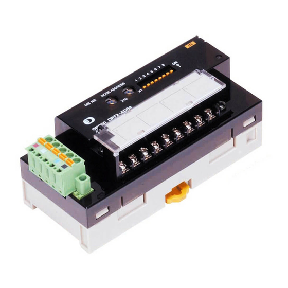
Master, and to set Ana- log Slave functions and perform monitoring. 7-1-2 Comparison of DRT1 and DRT2 Functions Analog Input Terminals Slave DRT1 Series DRT2 Series Model DRT1-AD04 DRT1-AD04H DRT2-AD04 Analog points 4 inputs Input range (signals) 0 to 5 V, 1 to 5 V, 0 to 10 V,–10... - Page 138 Section 7-1 Overview of Analog Slaves Slave DRT1 Series DRT2 Series Model DRT1-AD04 DRT1-AD04H DRT2-AD04 Input switching (Sets Supported. (Set using DIP Not supported. Supported (Set using Configu- number of AD con- switch: Select either 2 or 4 rator: Select from 1 to 4 points)
-
Page 139: List Of Data Processing Functions
Section 7-1 Overview of Analog Slaves Slave DRT1 Series DRT2 Series Model DRT1-DA02 DRT2-DA02 Communications error output Set using the DIP switch. Set using the Configurator. Scaling, user adjustment Not supported. Supported. (Set using the Configurator.) (maintenance function), cumu- lative counter (maintenance... -
Page 140: Analog Data Operation Flowcharts (Analog Input Terminals)
Section 7-1 Overview of Analog Slaves Function Details Default Error output value setting Sets the value output when a communications error occurs Low limit for each output. Last maintenance date Records the date of the last maintenance in the Unit. 2002/1/1 7-1-4 Analog Data Operation Flowcharts (Analog Input Terminals) -
Page 141: I/O Data Allocated In The Master
Section 7-1 Overview of Analog Slaves referred to as analog data, and can be allocated in the Master individually or in combination with Status Flags. The data is selected using the Configurator or explicit messages. For Analog Data 1, comparison operations with four alarm set values can be performed (comparator function). - Page 142 Section 7-1 Overview of Analog Slaves Individual Input Data I/O data Details Assembly Instance Analog Data 1 (8 input bytes) • Used for monitoring analog values. • Select one type of data from analog input value, peak value, bot- tom value, top value, valley value, or rate of change. (Default allo- cation: Analog input value) Note The comparator can be used with Analog Data 1.
-
Page 143: Allocating I/O Data In The Master
Generic Status Flags (11 input bytes) Note Data can be allocated using other data combinations, but only when an OMRON CS/CJ-series Master Unit is used. Analog Output Analog Output Terminals support one type of input data and output data each. - Page 144 Section 7-1 Overview of Analog Slaves Allocation method I/O data that can be allocated in the Master Allocated area in Allocated I/O data Master Fixed allocations Default I/O data allocation Allocates only analog input values for 4 points (8 input bytes).
-
Page 145: Procedure For Allocating I/O In The Master
Section 7-1 Overview of Analog Slaves 7-1-8 Procedure for Allocating I/O in the Master Application Step 1 Step 2 Step 3 Enable/disable Select analog 1. Allocate I/O 2. Allocate functions data data in fixed user-defined data combinations in user-defined area Set using the Configurator in the Set using the Set using the... -
Page 146: Application Procedure Flowchart
Section 7-1 Overview of Analog Slaves 7-1-9 Application Procedure Flowchart Connect the communications cables Set the node address (using rotary switches or Configurator) Use the same input range for Input 0 and 1 Use the same input range for Input 2 and 3 With the Configurator online, set the input range from Set the input range by turning ON DIP the Slave’s Edit Device Parameters Window, download... -
Page 147: Common Procedures
Section 7-2 Common Procedures Common Procedures 7-2-1 Connecting Communications Cables Communications cables are connected using the same methods as for Gen- eral-purpose Slaves. Refer to 5-2 Connecting Communications Cables to General-purpose Slaves for details. 7-2-2 Node Address and Baud Rate Settings The Analog Slaves’... -
Page 148: Mounting In Control Panels
Section 7-2 Common Procedures 2. The following window will be displayed. Enter the node address. 3. Click the OK Button. Note Any node address within the setting range can be used as long as it is not already set for another node. Setting the same node address for more than one node will cause a node address duplication error and communications will not start. -
Page 149: Wiring The I/O Lines
Section 7-3 Analog Input Terminals Mounting Direction Unless specific restrictions are given for the Slave, it can be mounted in any of the following six directions. 7-2-4 Wiring the I/O Lines The I/O lines are all wired to M3 screw terminals. Connect M3 crimp terminals to the wires and then connect them to the Termi- nal Block. - Page 150 Section 7-3 Analog Input Terminals Performance Specifications Item Specifications Voltage input Current input Input points 4 points (Inputs 0 to 3) Input signal range 0 to 5 V 0 to 20 mA 1 to 5 V 4 to 20 mA 0 to 10 V –10 to 10 V Input range setting method...
- Page 151 Section 7-3 Analog Input Terminals Setting the Input Signal Range Setting with the DIP The input range can be set using the DIP switch or the Configurator. Switch Each pin is set according to the following table. Pin No. Setting Specifications Input Terminal: Input range set- Default setting: All pins OFF...
- Page 152 Section 7-3 Analog Input Terminals the Configurator to set separate input signal ranges for each of the Inputs 0 to 3 if required. 2. When all the four inputs from 0 to 3 are not used, the number of AD con- version points can be set using the Configurator to speed up the conver- sion cycle for each input.
- Page 153 Section 7-3 Analog Input Terminals Wiring Connect the terminals of the Analog Input Terminal for each Input Unit accord- ing to the following diagrams, depending on whether a voltage input or a cur- rent input is being used. − − −...
- Page 154 Section 7-3 Analog Input Terminals Input Range: 0 to 10 V The voltage range 0 to 10 V corresponds to 0000 to 1770 hex (0 to 6,000). The convertible data range is FED4 to 189C hex ( 300 to 6,300). Negative –...
-
Page 155: I/O Data Allocation Methods
Section 7-3 Analog Input Terminals below the input range (input current less than 3.2 mA), a disconnection is detected and the data is set to 7FFF hex. Conversion data Hexadecimal (decimal) 189C (6300) 1770 (6000) 7FFF 3.2 mA Current 0000 (0) 4 mA 20 mA 20.8 mA FED4 (−300) - Page 156 Section 7-3 Analog Input Terminals Window, click the right mouse button over the Slave icon and select Pa- rameters and Edit.) 2. Click the Tab Page for the input where analog data is to be selected. From the data on which math operations have been performed, select two types of data from the pull-down menu as Analog Data 1 and Analog Data 2.
- Page 157 Section 7-3 Analog Input Terminals Example: Allocating Analog Data 1 + Top/Valley Detection Timing Flags in the Master. Analog Data 1 for Input 0 Analog Data 1 for Input 1 Analog Data 1 for Input 2 Analog Data 1 for Input 3 Top Detection Timing Flag Valley Detection Timing Flag The following method can be used to allocate data from the Configurator.
- Page 158 Section 7-3 Analog Input Terminals 1,2,3... 1. Double-click the icon of the Master Unit to which I/O will be allocated and open the Edit Device Parameters Window. (From the Maintenance Mode Window, click the right mouse button over the Master Unit icon and select Parameters and Edit.) 2.
- Page 159 Section 7-3 Analog Input Terminals Set the Cyclic settings (Analog Data 1 + Top/Valley Detection Timing Flags + Generic Status Flags in this example) to block 2, allocated 3500 (word CIO 3500). 6. Click the OK Button and use the following window to confirm that I/O has been allocated correctly.
- Page 160 Section 7-3 Analog Input Terminals The data format used for allocating data in the Master is shown below. Data is allocated as two’s complements (8 bytes = 4 words). Analog Data 1 for Input 0 Analog Data 1 for Input 1 Analog Data 1 for Input 2 Analog Data 1 for Input 3 Analog Data 2 (Instance...
- Page 161 Section 7-3 Analog Input Terminals Top/Valley Detection These flags turn ON for the one-shot time when detecting the top or valley for Timing Flags (Instance the top/valley hold function. 132) These flags are used to time reading the values held as the top and valley val- ues at the Master.
- Page 162 Section 7-3 Analog Input Terminals The details for each bit are shown in the following table. Abbrevia Name Details tion Compara- Low Low Limit Turns ON when the value of tor result Alarm Flag data allocated in Analog Data 1 drops below the Low Low Limit alarm setting.
- Page 163 Section 7-3 Analog Input Terminals Top/Valley Detection This data pattern consists of the Top/Valley Detection Timing Flags followed Timing Flags + Generic by Generic Status Flags and is allocated in the Master using the following Status Flags (Instance data format, shown by byte (3 bytes). 151) Bit 7 Bit 6...
- Page 164 Section 7-3 Analog Input Terminals The following format is used when this data pattern is allocated, starting from the rightmost byte of the Master Word 15 Analog Data 1 for Input 0 Analog Data 1 for Input 1 Analog Data 1 for Input 2 Analog Data 1 for Input 3 Top Detection Valley Detection...
-
Page 165: Functions And Settings
Section 7-3 Analog Input Terminals The details for each bit are shown in the following table. Abbreviation Name Details Hold Flag for The hold function is performed for Ana- Input 0 log Input 0 while this flag is ON. The hold function stops and the last value is held when the flag goes OFF. - Page 166 Section 7-3 Analog Input Terminals Conversion points Details 2 points Converting Inputs 0 and 1. DRT2-AD Used points 1 point Converting Input 0 only. DRT2-AD Used points Setting Using the DeviceNet Configurator 1,2,3... 1. Double-click the icon of the Analog Slave to be set in the Main Window and open the Edit Device Parameters Window.
- Page 167 Section 7-3 Analog Input Terminals When the input value fluctuates frequently, averaging can be used to produce a stable input value, as shown in the following diagram. Input analog value Actual input Averaged input Setting Using the DeviceNet Configurator 1,2,3... 1.
- Page 168 Section 7-3 Analog Input Terminals selected, scaling is performed according to the range used, as shown in the following table. Input 0 to 5 V 0 to 10 V 1 to 5 V 10 to 0 to 20 4 to 20 –...
- Page 169 Section 7-3 Analog Input Terminals Upper limit 7FFE 100% scaling value Scaled line 0% scaling Offset value (–28,000 to 28,000) Input signal range 100% Setting Using the DeviceNet Configurator 1,2,3... 1. Double-click the icon of the Analog Slave to be set in the Main Window and open the Edit Device Parameters Window.
- Page 170 Section 7-3 Analog Input Terminals 3. Click the Scaling Tab, and select either Default Scaling or User Scaling. 4. For user scaling, set the 0% value in the Scaling point 1 field, and set the 100% value in the Scaling point 2 field.
- Page 171 Section 7-3 Analog Input Terminals 5. For offset compensation, set the offset value in the Scaling Offset field. Also select either Default Scaling or User Scaling in the Scaling Type field. 6. Return to the General Tab, click the Download Button, and then click the Reset Button to reset the Unit.
- Page 172 Section 7-3 Analog Input Terminals program that considers the transmission delay when the Hold Flag is turned ON, then enables the peak/bottom hold values after a fixed time interval. Setting Using the DeviceNet Configurator 1,2,3... 1. Double-click the icon of the Analog Slave to be set in the Main Window and open the Edit Device Parameters Window.
- Page 173 Section 7-3 Analog Input Terminals 5. Click the Download Button and then click the Reset Button to reset the Unit. 6. Click the OK Button and exit the window. Top/Valley Hold Top/valley hold is used to hold the top and valley values of the analog input value.
- Page 174 Section 7-3 Analog Input Terminals 2. Select the Tab Page for the input where top/valley hold is to be set, and se- lect Top/Valley Hold under the Function Choice heading. 3. Return to the General Tab, click the Download Button, and then click the Reset Button to reset the Unit.
- Page 175 Section 7-3 Analog Input Terminals Timing for Setting Data Analog input value Set hysteresis value x 2 Valley hold value Top/Valley Detection Timing Flag Delay Setting Hysteresis Using the DeviceNet Configurator 1,2,3... 1. Input the value for hysteresis in the Hysteresis field in the Top/Valley Tab under the Function Choice heading.
- Page 176 Section 7-3 Analog Input Terminals One-shot Time Setting 1,2,3... 1. Input the desired value in the SHOT Off Delay field of the Top/Valley Tab under the Function Choice heading. 2. Return to the General Tab, click the Download Button, and then click the Reset Button to reset the Unit.
- Page 177 Section 7-3 Analog Input Terminals regarded as the rate of change. To prevent this occurring, use moving aver- age processing, which will set a longer sampling cycle. Desired gradient Fluctuation in analog value Short sampling cycle Long sampling cycle Setting Using the DeviceNet Configurator 1,2,3...
- Page 178 Section 7-3 Analog Input Terminals 3. To set the sampling cycle, click the Rate of Change Tab and input the de- sired value for the sampling cycle in the Sampling Rate field. 4. Return to the General Tab, click the Download Button, and then click the Reset Button to reset the Unit.
- Page 179 Section 7-3 Analog Input Terminals threshold, and the flag repeatedly turns ON or OFF, setting hysteresis will sta- bilize the flag operation. HH set value or Hysteresis width H set value Hysteresis width LL set value or L set value LL Alarm Flag or L Alarm Flag HH Alarm Flag or...
- Page 180 Section 7-3 Analog Input Terminals 3. Click the Comparator Tab and set each of the alarm values. The example here shows the setting for Alarm Trip Point High (HH limit set value). 4. To set the hysteresis value, input the desired value in the Hysteresis field. Note The hysteresis value set for the comparator function is also used by the top/valley hold function.
- Page 181 Section 7-3 Analog Input Terminals 5. To set the OFF delay function, input the desired value in the Comparator Off Delay field. 6. Return to the General Tab, click the Download Button, and then click the Reset Button to reset the Unit. 7.
- Page 182 Section 7-3 Analog Input Terminals The following table shows the input ranges that support user adjustment. Input range Low Limit High Limit 0 to 5 V –0.25 to 0.25 V 4.75 to 5.25 V 1 to 5 V –0.8 to 1.2 V 4.8 to 5.2 V 0 to 10 V –0.5 to 0.5 V...
- Page 183 Section 7-3 Analog Input Terminals 6. Click the Fix lower adjusting value Button, and input the adjusted value. 7. To return an adjusted value to the default setting, click the Default Setting Button. 8. Close the Adjustment Window, return to the General Tab, click the Down- load Button, and then click the Reset Button to reset the Unit.
- Page 184 Section 7-3 Analog Input Terminals Setting Using the DeviceNet Configurator 1,2,3... 1. Double-click the icon of the Analog Slave to be set in the Main Window and open the Edit Device Parameters Window. (From the Maintenance Mode Window, click the right mouse button over the Slave icon and select Pa- rameters and Edit.) 2.
- Page 185 Section 7-3 Analog Input Terminals 4. To set the monitor value, click the Cumulated Count Tab, and input the de- sired value in the Threshold Cumulated Counter field. 5. Return to the General Tab, click the Download Button, and then click the Reset Button to reset the Unit.
- Page 186 Section 7-3 Analog Input Terminals 2. Click the General Tab, and select the applicable date from the pull-down menu in the Last Maintenance Date field. (To enter the current date, select Today, which is at the bottom of the pull-down menu.) 3.
-
Page 187: Calculating The Conversion Cycle
Section 7-3 Analog Input Terminals from the pull-down menu in the Last Maintenance Date field. (To enter the current date, select Today, which is at the bottom of the pull-down menu.) 3. Return to the General Tab, click the Download Button, and then click the Reset Button to reset the Unit. -
Page 188: Analog Output Terminals
Section 7-4 Analog Output Terminals Math operation Additional time for each point Rate of change 0.030 Cumulative counter 0.035 Calculation Example When using three points, and applying scaling to the first and second inputs, and the cumulative counter to the third input, the maximum AD conversion cycle time can be obtained by using the following formula. - Page 189 Section 7-4 Analog Output Terminals Item Specifications Voltage output Current output DA conversion data –10 to 10 V range: F448 to 0BB8 hex full scale (–3,000 to 3,000) Other ranges: 0000 to 1770 hex full scale (0 to 6,000) ± DA conversion range: 5% FS of the above data ranges.
- Page 190 Section 7-4 Analog Output Terminals 2. Always set pin 8 to ON if the DIP switch is used to set the range. If this pin is OFF, the DIP switch settings will not be enabled. 3. The DIP switch settings are read when the power is turned ON. Output Range Settings Output 0 Signal range...
- Page 191 Section 7-4 Analog Output Terminals 5. Click the OK Button and exit the window. Internal Circuits − Analog GND The negative terminals for output 0 and output 1 are connected internally. Wiring The terminal wiring varies according to whether voltage or current output is used.
- Page 192 Section 7-4 Analog Output Terminals Output Range: 1 to 5 V The values 0000 to 1770 hex (0 to 6,000) correspond to the voltage range 1 to 5 V. The output range is 0.8 to 5.2 V. Voltage 5.2 V 0.8 V Conversion data Hexadecimal (decimal)
-
Page 193: I/O Data Types And Allocation Methods
Section 7-4 Analog Output Terminals Output Range: 0 to 20 mA The values 0000 to 1770 hex (0 to 6,000) correspond to the current range 0 to 20 mA. The output range is 0 to 21 mA. Current 21 mA 20 mA 0 mA Conversion data... - Page 194 Section 7-4 Analog Output Terminals I/O Data Allocated in the Master Allocating Only Analog Output Values (Default I/O Data) When using the Analog Output Terminal’s default settings, only the analog output values are allocated as I/O in the two words (four bytes) of the Master’s OUT Area.
- Page 195 Section 7-4 Analog Output Terminals Allocating User-defined I/O Data Analog data that has been processed using math operations and Status Flags can be selected and allocated as I/O in the Master in any combination. The Configurator can be used to allocate the I/O in the Master. This method is supported by CS/CJ-series DeviceNet Master Units only.
- Page 196 Section 7-4 Analog Output Terminals Connection, and then select Generic Status from the pull-down menu in the Con. Path field for input. 4. Click the OK Button. 5. Click the I/O Allocation (IN) or I/O Allocation (OUT) Tab, and edit the I/O allocations.
- Page 197 Section 7-4 Analog Output Terminals 6. Click the OK Button and use the following window to confirm that I/O has been allocated correctly. 7. Return to the General Tab, and click the Download Button. 8. Click the OK Button and exit the window. I/O Data (Patterns) Analog Output Data Analog Output Data is used to allocate two words (four bytes) of output data in...
-
Page 198: Functions And Setting Methods
Section 7-4 Analog Output Terminals Abbrevia- Name Details tion Unit Error Flag Turns ON when analog con- version stops due to a Unit error. Reserved. (Always 0.) The following format is used when the Generic Status Flags are allocated, starting from the rightmost byte of the Master Word Generic Status Flags 7-4-3... - Page 199 Section 7-4 Analog Output Terminals User Scaling User scaling allows analog output values to be scaled to user-defined values. The conversion values for 100% and 0% are set using the Configurator. Input 0 to 5 V 0 to 10 V 1 to 5 V –10 to 0 to 20...
- Page 200 Section 7-4 Analog Output Terminals Setting Using the DeviceNet Configurator 1,2,3... 1. Double-click the icon of the Analog Slave to be set in the Main Window and open the Edit Device Parameters Window. (From the Maintenance Mode Window, click the right mouse button over the Slave icon and select Pa- rameters and Edit.) 2.
- Page 201 Section 7-4 Analog Output Terminals 4. For user scaling, set the 0% value in the Scaling point 1 field, and set the 100% value in the Scaling point 2 field. 5. For offset compensation, set the offset value in the Scaling Offset field. Also select either Default Scaling or User Scaling in the Scaling Type field.
- Page 202 Section 7-4 Analog Output Terminals User Adjustment Depending on factors such as the characteristics and connection methods of the output device, the output can be adjusted to compensate for error in the final output. The following diagram shows when compensation is applied to the conversion line at the two points for 0% and 100%.
- Page 203 Section 7-4 Analog Output Terminals 2. Select the Tab Page for the output to be adjusted, and click the Adjust- ment Button. (At the same time set the output range again.) Adjusting the Low Limit 3. Output the value that is equivalent to 0% from the Master Unit. Always per- form adjustment with the 0% value.
- Page 204 Section 7-4 Analog Output Terminals correct 100% value is output from the output device. After compensation is completed, click the Fix upper adjusting value Button. Note If the High Limit adjustment is not performed for the 100% value, a discrep- ancy will occur when the Low Limit is adjusted, so always adjust the Low Limit of Output Terminals before adjusting the High Limit.
- Page 205 Section 7-4 Analog Output Terminals Setting Using the DeviceNet Configurator 1,2,3... 1. Double-click the icon of the Analog Slave to be set in the Main Window and open the Edit Device Parameters Window. (From the Maintenance Mode Window, click the right mouse button over the Slave icon and select Pa- rameters and Edit.) 2.
- Page 206 Section 7-4 Analog Output Terminals 4. To set the monitor value, click the Cumulated Count Tab, and input the de- sired value in the Threshold Cumulated Counter field. 5. Return to the General Tab, click the Download Button, and then click the Reset Button to reset the Unit.
- Page 207 Section 7-4 Analog Output Terminals 2. Select the Tab Page for the output where the error output value is to be set, and select the desired item from the pull-down menu in the Fault State field. 3. Return to the General Tab, click the Download Button, and then click the Reset Button to reset the Unit.
- Page 208 SECTION 8 Communications Timing This section provides information on the time required for a complete communications cycle, for an output response to be made to an input, to start the system, and to send messages. Remote I/O Communications Characteristics......8-1-1 I/O Response Time .
-
Page 209: Remote I/O Communications Characteristics
Remote I/O Communications Characteristics This section describes the characteristics of DeviceNet remote I/O communi- cations when OMRON Master and Slave Units are being used. Use this sec- tion for reference when planning operations that require precise I/O timing. The equations provided here are valid under the following conditions: •... - Page 210 Section 8-1 Remote I/O Communications Characteristics The Output Slave’s communications time/Slave (Refer to RT-OUT page 198.) The PLC’s peripheral servicing cycle time PLC2 Note Refer to SECTION 5 General-purpose Slaves and SECTION 6 Environment- resistive Slaves for details on Input and Output Slaves’ ON and OFF delay times.
- Page 211 Section 8-1 Remote I/O Communications Characteristics CVM1- and CV-series PLCs (Synchronous Mode) Minimum I/O Response The minimum I/O response time occurs with the I/O timing shown in the fol- Time lowing diagram. Cycle time Instruction Periph- Instruction Periph- Periph- Instruction eral ser- eral ser- eral ser-...
- Page 212 Section 8-1 Remote I/O Communications Characteristics Maximum I/O Response The maximum I/O response time occurs with the I/O timing shown in the fol- Time lowing diagram. Cycle time Periph- Instruction Periph- Instruction Periph- Periph- Instruction Instruction eral ser- eral ser- eral ser- eral ser- execution...
- Page 213 Section 8-1 Remote I/O Communications Characteristics CS, CJ, C200HX/HG/HE (-Z), and C200HS PLCs Minimum I/O Response The minimum I/O response time occurs when the DeviceNet Slave I/O Time refreshing is executed just after the input signal is received by the Master and I/O is refreshed for the Slave first in the next I/O refresh cycle.
-
Page 214: Communications Cycle Time And Refresh Time
Section 8-1 Remote I/O Communications Characteristics Maximum I/O Response The maximum I/O response time occurs with the I/O timing shown in the fol- Time lowing diagram. Instruction Instruction Instruction execution execution execution Master Unit Input Output The Input Slave’s ON (OFF) delay The Output Slave’s ON (OFF) delay The whole Network’s communications cycle time (Refer to page 198.) - Page 215 Section 8-1 Remote I/O Communications Characteristics = Σ (communications time for each Slave) + MULTIPLE I/O TERMINAL processing time + Explicit messages processing time + 0.01 × N + 1.0 [ms] Communications time for each Slave: Time required for each Slave. (Refer to page 7-9.) Σ (communications time for each Slave) is the total of the processing of each Slave in the Network.
-
Page 216: More Than One Master In Network
Section 8-1 Remote I/O Communications Characteristics The number of output bytes Baud rate BYTE-IN BYTE-OUT 500 kbps 0.306 ms 0.040 ms 0.036 ms 250 kbps 0.542 ms 0.073 ms 0.069 ms 125 kbps 1.014 ms 0.139 ms 0.135 ms The number of output bytes (B ) for Input Slaves only is 0, and the number of input bytes (B ) for Output Slaves only is 0. -
Page 217: System Startup Time
Section 8-1 Remote I/O Communications Characteristics First, the Network is divided into two groups: Master A and the Slaves in remote I/O communications with it, and Master B and the Slaves in remote I/O communications with it. Group B Group A Master B Master A Slave a... -
Page 218: Message Communications Characteristics
Section 8-2 Message Communications Characteristics Program Example As shown in the preceding table, it takes time for DeviceNet communications to start up. This programming uses flags in the Master Status Area to prevent the Slaves’ I/O processing from being performed until the Master Unit and remote I/O communications have started up. - Page 219 Section 8-2 Message Communications Characteristics Message Message communications time = 2 (see note) + 0.11 × T + 0.6 (ms) Communications : Baud rate (500 kbps: T = 2; 250 kbps: T = 4; 125 kbps: T = 8) Only (Remote I/O Communications Not Used) Note The communications cycle when remote I/O communications are not being...
- Page 220 SECTION 9 Troubleshooting and Maintenance This section describes error processing, periodic maintenance operations, and troubleshooting procedures needed to keep the DeviceNet Network operating properly. We recommend reading through the error processing procedures in both this manual and the operation manual for the master being used before operation so that operating errors can be identified and corrected more quickly.
-
Page 221: Indicators And Error Processing
Section 9-1 Indicators and Error Processing Indicators and Error Processing 9-1-1 Error Occurring in the Slave Unit MS/NS indicators Details Probable cause and remedy Remote I/O communi- Remote I/O Commu- Remote I/O communications and/or cations or message nications or message message communications are being ON (green) communications in... -
Page 222: Troubleshooting
Section 9-2 Troubleshooting MS/NS indicators Details Probable cause and remedy Bus Off error detected Bus Off status (com- Check the following items and restart munications stopped the Slave. ON (green) due to multiple data Do Master/Slave baud rates match? errors) Are lengths of cables (trunk and branch lines) correct? ON (red) - Page 223 If there is nearby equipment that generates electrical noise, take steps to shield the Master, Slaves, and communications cables from the noise. If an error has occurred in a network with an OMRON Master Unit, refer to the Mas- ter Unit's Operation Manual.
-
Page 224: Maintenance
If another company’s Master is being used, refer to the relevant operation manual. Check whether the Slave is registered in the Master’s scan list. If an OMRON Master Unit is being used, a new Slave cannot be added to the network if the Master is operating with the scan list enabled. -
Page 225: Inspection
After replacement make sure that there are no errors with the new Unit. When a Unit is being returned for repair, attach a sheet of paper detailing the problem and return the Unit to your OMRON dealer. If there is a faulty contact, try wiping the contact with a clean, lint-free cloth dampened with alcohol. - Page 226 Note The number of bytes designated for Class ID, Instance ID, and Attribute ID depend on the Master Unit. When sent from an OMRON DeviceNet Master, the Class ID and Instance ID are 2 bytes (4 digits), and Attribute ID is 1 byte (2 digits).
- Page 227 Appendix A DeviceNet Explicit Messages Service Code For normal completion, the value when the leftmost bit of the service code specified in the command turns ON is stored as shown in the following table. Function Command service code Response service code Read data 10 Hex 90 Hex...
- Page 228 Appendix A DeviceNet Explicit Messages Setting and Monitoring the Unit Conduction Time Explicit Read/ Function Command Response message write Service Class ID Instance Attribute Data size code Unit Main- Read Reads the set value 0E Hex 95 Hex 01 Hex 73 Hex 4 bytes tenance Set...
- Page 229 Appendix A DeviceNet Explicit Messages Explicit Read/ Function Command Response message write Service Class Instance Attribute Data size code Set value Read Reads the set value for 0E Hex 08 Hex 01 to 20 68 Hex 4 bytes (input) for the total ON time (unit: 00000000 to Total ON...
- Page 230 Appendix A DeviceNet Explicit Messages Setting and Monitoring the Terminal (Output) Explicit Read Function Command Response message /write Service Class Instance Attribute Data size code Terminal Read Reads the monitor mode 0E Hex 09 Hex 01 to 20 65 Hex 1 byte Mainte- for maintenance infor-...
- Page 231 Appendix A DeviceNet Explicit Messages Setting and Monitoring Operation Time Explicit Read Function Command Response message /write Service Class ID Instance Attribut Data size code e ID Set Value Read Reads the monitor value 0E Hex 97 Hex 01 to 10 67 Hex 2 bytes for Opera-...
- Page 232 Appendix A DeviceNet Explicit Messages Setting and Monitoring Detection of Sensor Power Short-circuit Explicit Read/ Function Command Response message write Service Class ID Instance Attribute Data size code Sensor Read Reads the short-circuit 0E Hex 08 Hex 01 to 10 69 Hex 1 byte Power...
- Page 233 Appendix A DeviceNet Explicit Messages Explicit Read/ Function Command Response message write Service Class ID Instance Attribute Data size code Sensor Dis- Read Reads the Sensor con- 0E Hex 08 Hex 01 to 10 6A Hex 1 byte connected nected/disconnected 00 Hex: Status status for the input (No.
- Page 234 Appendix A DeviceNet Explicit Messages Writing Maintenance Information Explicit Read/ Function Command Response message write Service Class ID Instance Attribute Data size code Mainte- Save Records the mainte- 16 Hex 95 Hex 01 Hex 75 Hex nance nance counter in the Counter Slave’s memory.
- Page 235 Appendix A DeviceNet Explicit Messages Note 1. The Attribute (7E Hex) is bit 7 of the Generic Status and so the size is fixed at 4 bytes and has the following format. Size, 0002 Fixed IN+OUT combined, terminals 0 to 7 The bit turns ON when the set value is exceeded.
- Page 236 Appendix A DeviceNet Explicit Messages Setting and Reading for Analog Input Terminals Explicit Read Function Command Response message /write Service Class Instance Attribute Data size code Analog Read Reads the value for 0E Hex 0A Hex 01 to 04 03 Hex 2 bytes 2 byte Data 1...
- Page 237 Appendix A DeviceNet Explicit Messages Explicit Read Function Command Response message /write Service Class Instance Attribute Data size code Scaling Write/ Sets an analog value as Write: 0A Hex 01 to 04 70 Hex 2 bytes 2 bytes Point 1 Set- Read the 0% value for user 10 Hex...
- Page 238 Appendix A DeviceNet Explicit Messages Explicit Read Function Command Response message /write Service Class Instance Attribute Data size code Rate of Read Reads the rate of 0E Hex 0A Hex 01 to 04 8E Hex 2 bytes Change change for each sam- Value Read pling cycle.
- Page 239 Appendix A DeviceNet Explicit Messages Setting and Reading for Analog Output Terminals Explicit Read Function Command Response message /write Service Class Instance Attribute Data size code Analog Out- Read Reads analog output 0E Hex 0B Hex 01 to 02 03 Hex 2 bytes put Value values.
- Page 240 Appendix A DeviceNet Explicit Messages Explicit Read Function Command Response message /write Service Class Instance Attribute Data size code Cumulative Write/ Sets the unit for the Write: 0B Hex 01 to 02 94 Hex 1 byte Counter Read cumulative counter. 10 Hex Unit Setting 0: Hour (count hours);...
- Page 241 Appendix A DeviceNet Explicit Messages The command data is written in words starting from D01000 in the PLC and the response data is stored in words starting from D02000. If the command does not end normally, the end code is stored in D00006 and the send command is re-exe- cuted.
- Page 242 Appendix B Using Another Company’s Master Unit This appendix explains how to operate an OMRON Slave when the Slave is connected to a Master manufac- tured by another company. Note If the Slave has outputs, do not communicate with the Master through a bit strobe connection.
- Page 243 Device Profiles of General-purpose and Environment-resistive Slaves General data Compatible DeviceNet Specifications Volume I - Release 1.3 Volume II - Release 1.3 Vendor name OMRON Corporation Vendor ID = 47 Device profile name Slaves: Generic purpose Profile number = 7 Discrete I/O...
- Page 244 Device Profiles of Analog Slaves General data Compatible DeviceNet Specifications Volume I - Release 1.3 Volume II - Release 1.3 Vendor name OMRON Corporation Vendor ID = 47 Device profile name Slaves: Generic Profile number = 0 Manufacturer catalog number...
- Page 245 Appendix B Using Another Company’s Master Unit Object Mounting Identity Object (0x01) Object class Attribute Not supported Service Not supported Object Attribute Contents Get (read) Set (write) Value instance Vendor Device type See note. Product code See note. Revision Status (bits supported) Bit 0 only Serial number Unique for each Unit...
- Page 246 Appendix B Using Another Company’s Master Unit Model Device type Product Product name code DRT2-OD16 XWT-OD16-1 DRT2-OD16 DRT2-OD16-1 None DRT2-OD16-1 DRT2-OD16-1 XWT-ID08 DRT2-OD16-1 DRT2-OD16-1 XWT-ID16 DRT2-OD16-1 DRT2-OD16-1 XWT-OD08 DRT2-OD16-1 DRT2-OD16-1 XWT-OD16 DRT2-OD16-1 DRT2-OD16-1 XWT-ID08-1 DRT2-OD16-1 DRT2-OD16-1 XWT-ID16-1 DRT2-OD16-1 DRT2-OD16-1 XWT-OD08-1 DRT2-OD16-1 DRT2-OD16-1 XWT-OD16-1...
- Page 247 Appendix B Using Another Company’s Master Unit Message Router Object (0x02) Object class Attribute Not supported Service Not supported Object instance Attribute Not supported Service Not supported Vendor specifica- None tion addition DeviceNet Object (0x03) Object class Attribute Not supported Service Not supported Object...
- Page 248 Appendix B Using Another Company’s Master Unit General-purpose Slaves (Input) Instance number Type Bit allocation Supported model Assembly instance 4 Input DRT2-OD16(-1) + XWT-ID08(-1) 8 inputs DRT2-ID08C(-1) Assembly instance 5 Input DRT2-ID16(-1) 16 inputs DRT2-ID16(-1) + XWT-OD08(-1) DRT2-ID16(-1) + XWT-OD16(-1) DRT2-OD16(-1) + XWT-ID16(-1) DRT2-HD16C(-1) Assembly instance 6...
- Page 249 Appendix B Using Another Company’s Master Unit General-purpose Slaves (Output) Instance number Type Bit allocation Supported model Assembly instance 34 Output DRT2-ID16(-1) + XWT-OD08(-1) 8 outputs DRT2-OD08C(-1) Assembly instance 35 Output DRT2-OD16(-1) 16 outputs DRT2-ID16(-1) + XWT-OD16(-1) DRT2-OD16(-1) + XWT-ID08(-1) DRT2-OD16(-1) + XWT-ID16(-1) Assembly instance 36 Output...
- Page 250 Appendix B Using Another Company’s Master Unit Instance number Byte Bit allocation Supported model Instance 144 Input 0, Analog Data 1 DRT2-AD04 Analog Data 1 + Ana- log Data 2 Input 1, Analog Data 1 Input 2, Analog Data 1 Input 3, Analog Data 1 Input 0, Analog Data 2 Input 1, Analog Data 2...
- Page 251 Appendix B Using Another Company’s Master Unit Analog Slaves (Output) Instance number Byte Bit allocation Supported model Instance 190 DRT2-AD04 Hold Flags Instance 192 Input 0, Analog Data DRT2-DA02 Analog output data Input 1, Analog Data...
- Page 252 Appendix B Using Another Company’s Master Unit Connection Object (0x05) Object class Attribute Not supported Service Not supported Maximum number of active connections Object Section Information Maximum number of instances instance 1 Instance type Explicit Message Production Cyclic trigger Transport type Server Transport class Attribute...
- Page 253 Appendix B Using Another Company’s Master Unit Object Section Information Maximum number of instances instance 2 Instance type Explicit Message Production Cyclic trigger Transport type Server Transport class Attribute Contents Get (read) Set (write) Value State Instance type 01 (hexadeci- mal) Transport class 82 (hexadeci-...
- Page 254 Appendix B Using Another Company’s Master Unit Model Name Produced Produced Produced Consumed Consumed Consumed connection connection connection connection connection connection Basic Unit Expansion size path length path size path length path Unit DRT2- None Input Data 0002 (hexa- 0006 20_04_24_ 0000 ID16(-1)
- Page 255 Appendix B Using Another Company’s Master Unit Model Name Produced Produced Produced Consumed Consumed Consumed connection connection connection connection connection connection Basic Unit Expansion size path length path size path length path Unit DRT2- XWT-ID16 Output Data - 0000 0002 (hexa- 0006 20_04_24_ OD16(-1)
- Page 256 Appendix B Using Another Company’s Master Unit Model Name Produced Produced Produced Consumed Consumed Consumed connection connection connection connection connection connection Basic Unit Expansion size path length path size path length path Unit DRT2-AD04 Analog data 0010 (hexa- 0006 20_04_24_ 0000 (hexa- 0000 1 + Analog...
- Page 257 Appendix B Using Another Company’s Master Unit Object Section Information Maximum number of instances instance 3 Instance type Explicit Message Production Cyclic trigger Transport type Server Transport class Attribute Contents Get (read) Set (write) Value State Instance type 01 (hexadeci- mal) Transport class 82 (hexadeci-...
- Page 258 Appendix B Using Another Company’s Master Unit Model Name Produced Produced Produced Consumed Consumed connection connection connection connection connection Basic Unit Expan- size path length path path length path sion Unit DRT2- None Input Data 0002 (hexa- 0006 20_04_24_05 0000 ID16(-1) decimal) _30_03...
- Page 259 Appendix B Using Another Company’s Master Unit Model Name Produced Produced Produced Consumed Consumed connection connection connection connection connection Basic Unit Expan- size path length path path length path sion Unit DRT2- XWT- Output Data 0000 0006 OD16(-1) ID16(-1) Input Data 0002 (hexa- 0006 20_04_24_05...
- Page 260 Appendix B Using Another Company’s Master Unit Object Section Information Maximum number of instances instance 4 Instance type COS Cyclic Production Cyclic trigger Transport type Server Transport class Attribute Contents Get (read) Set (write) Value State Instance type 01 (hexadeci- mal) Transport class trigger...
- Page 261 Appendix B Using Another Company’s Master Unit Model Name Produced Produced Produced Consumed Consumed connection connection connection connection connection Basic Unit Expan- size path length path path length path sion Unit DRT2- None Input Data 0002 (hexa- 0006 20_04_24_05 0000 ID16(-1) decimal) _30_03...
- Page 262 Appendix B Using Another Company’s Master Unit Model Name Produced Produced Produced Consumed Consumed connection connection connection connection connection Basic Unit Expan- size path length path path length path sion Unit DRT2- XWT- Output Data 0000 0006 OD16(-1) ID16(-1) Input Data 0002 (hexa- 0006 20_04_24_05...
- Page 263 Appendix B Using Another Company’s Master Unit Model Name Produced Produced Produced Consumed Consumed connection connection connection connection connection Basic Unit Expan- size path length path path length path sion Unit DRT2-AD04 Analog data 1 0010 (hexa- 0006 20_04_24_90 0000 + Analog data decimal) _30_03...
- Page 264 Appendix C Connectable Devices General-purpose Slaves Model Specifications Manufacturer DRT2-ID16 Remote I/O Terminal with 16 transistor inputs (NPN) OMRON DRT2-ID16-1 Remote I/O Terminal with 16 transistor inputs (PNP) OMRON DRT2-OD16 Remote I/O Terminal with 16 transistor outputs (NPN) OMRON DRT2-OD16-1...
- Page 265 Cable with shielded mini-size connector on one end (male plug) OMRON Note 1. The cables made by Nihon Wire & Cable Company Ltd. Are sold through the OMRON 24 Service Co., Ltd. The product specifications are identical to the OMRON cable specifications.
- Page 266 Reverse current prevention, ground terminal provided. DCN1-1P One-branch tap for power supply. OMRON Use this tap when connecting a communications power supply. Two connectors and two fuses are standard. Note The Power Supply Sharing Taps are sold through the OMRON 24 Service Co., Ltd.
- Page 267 DRT2-OD08C(-1) Model Specifications Manufacturer XS4W-D421-1@@-A Cable with connectors on both ends (socket and plug) OMRON XS4F-D421-1@@-A Cable with connector on one end (female socket) XS4H-D421-1@@-A Cable with connector on one end (male plug) Always use DeviceNet Communications Connectors that conform to DeviceNet Connector standards.
- Page 268 Appendix D Current Consumption Summary General-purpose Slaves Model Communications current consumption DRT2-ID16 60 mA max. DRT2-ID16-1 60 mA max. DRT2-OD16 60 mA max. DRT2-OD16-1 60 mA max. XWT-ID08 (See note.) 5 mA max. XWT-ID08-1 (See note.) 5 mA max. XWT-ID16 (See note.) 10 mA max.
- Page 269 Appendix D Current Consumption Summary...
- Page 270 Appendix E Precautions with Connecting Two-wire DC Sensors When using a two-wire Sensor with a Slave using transistor inputs, check that the following conditions have been met. Failure to meet these conditions may result in operating errors. Relation between ON Voltage of Slave with Transistor Inputs and Sensor Residual Voltage ≤...
- Page 271 Appendix E Precautions with Connecting Two-wire DC Sensors Relation between OFF Current of Slave with Transistor Inputs and Sensor Leakage Current ≥ I leak OFF current of a Slave with Transistor Inputs Sensor’s leakage current leak Connect a bleeder resistor if I is greater than I leak The bleeder resistor constant can be calculated using the following equation.
- Page 272 Index AD conversion cycle time cables calculating communications cables xvii Analog Slaves AD conversion points Environment-resistive Slaves analog data Environment-resistive Terminals Analog Output Data General-purpose Slaves operation flowcharts models rate of change nodes selecting connecting Analog Input Terminals to Analog Slaves AD conversion data to Environment-resistive Slaves dimensions...
- Page 273 Index changing square setting Contact Operation Counter cycle time Contact Operation Monitor DeviceNet remote I/O Control Panels errors mounting in history monitor control system hold/clear crimp terminals output values models settings cumulative counter message communications time divisions refresh time specifications Cumulative Counter Flag starting timing...
- Page 274 Index maintaining remote I/O communications data allocation Environment-resistive Slaves specifications cables weight current consumption enclosure ratings Generic Status Flags functions grounding indicators precautions models precautions xvii remote I/O communications data allocation Hold Flag specifications hysteresis weight Environment-resistive Terminals baud rate communications cables features I/O comments...
- Page 275 Index replacing Units application writing maintenance dates cables xvii circuits Masters connecting two-wire DC sensors from other companies connectors mounting EC Directives xviii settings environment message communications time general xiii mounting grounding moving average processing packing multi-drop connections power supply safety scan list xvii...
- Page 276 Index Analog Output Terminals DRT2-HD16C (NPN) communications DRT2-HD16C-1 (PNP) Environment-resistive Slaves DRT2-ID08C (NPN) Environment-resistive Terminals DRT2-ID16 (NPN) Expansion Units DRT2-ID16-1 (PNP) General-purpose Slaves DRT2-OD08C (NPN) Remote I/O Terminals DRT2-OD08C-1 (PNP) Slaves (common) DRT2-OD16 (NPN) DRT2-OD16-1 (PNP) switches Expansion Units DIP switches I/O lines reading I/O power supply...
- Page 277 Index...
- Page 278 Revision History A manual revision code appears as a suffix to the catalog number on the front cover of the manual. Cat. No. W404-E1-01 Revision code The following table outlines the changes made to the manual during each revision. Page numbers refer to the previous version.
- Page 279 Revision History...
- Page 280 Wegalaan 67-69, NL-2132 JD Hoofddorp The Netherlands Tel: (31)2356-81-300/Fax: (31)2356-81-388 OMRON ELECTRONICS LLC 1 East Commerce Drive, Schaumburg, IL 60173 U.S.A. Tel: (1)847-843-7900/Fax: (1)847-843-8568 OMRON ASIA PACIFIC PTE. LTD. 83 Clemenceau Avenue, #11-01, UE Square, Singapore 239920 Tel: (65)6835-3011/Fax: (65)6835-2711...
- Page 281 Authorized Distributor: Cat. No. W404-E1-01 Note: Specifications subject to change without notice Printed in Japan...