Sign In
Upload
Manuals
Brands
Omron Manuals
Network Hardware
DeviceNet XWT-OD08
Omron DeviceNet XWT-OD08 Manuals
Manuals and User Guides for Omron DeviceNet XWT-OD08. We have
3
Omron DeviceNet XWT-OD08 manuals available for free PDF download: Operation Manual, User Manual
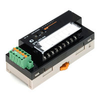
OMRON DeviceNet XWT-OD08 Operation Manual (596 pages)
DeviceNet Slaves
Brand:
OMRON
| Category:
Network Hardware
| Size: 12.97 MB
Table of Contents
Table of Contents
7
Precautions
14
Intended Audience
15
General Precautions
16
Safety Precautions
17
Operating Environment Precautions
18
Application Precautions
19
Conformance to EC Directives
21
Applicable Directives
21
Concepts
21
Section 1 Smart Slaves and Features
22
Smart Slaves and Features
22
DRT2 Features
23
Overview
23
Features
23
DRT2 Slaves
28
General-Purpose Slaves
28
Environment-Resistive Slaves
30
Analog Slaves
31
Smart Slave Feature Support
32
Installing and Connecting Slaves
38
Section 2 Example System Startup
42
Example System Startup
42
Basic Procedures and Configuration Examples
43
Basic Procedures
43
System Configuration Example
43
Preparations
44
Selecting Units
44
Wiring
44
Communications Power Supply
44
Setting and Wiring Hardware
45
Mounting and Setting the Master Unit
45
Mounting and Setting Slaves
46
Mounting Connecting Devices
47
Connecting Cables
47
Starting Communications
48
Creating I/O Tables for the Master Unit
48
Starting the System
49
Creating and Registering Scan Lists
49
Checking Operation
50
Indicator Status
50
Reading and Writing Data
50
Section 3 Common Slave Specifications
52
Common Slave Specifications
52
Common Slave Specifications
53
Communications Specifications
53
MS and NS Indicators
53
Devicenet Remote I/O Communications
55
Overview of Remote I/O Allocations for Smart Slaves
55
I/O Allocations for Smart Slaves
57
I/O Allocation with the Configurator (Ver. 2.@ or Later)
63
Section 4 Functions of All Slaves, General-Purpose Slaves, and Environment-Resistive Slaves
68
And Environment-Resistive Slaves
68
Maintenance Mode Window and Main Window
69
Normal Window
69
Maintenance Mode Window
70
Device Monitor Window
72
Common Slave Functions
73
Automatic Baud Rate Recognition
73
Network Power Supply Voltage Monitor
74
Unit Conduction Time Monitor
75
Slave Comments
76
I/O Comments
78
Communications Error History Monitor
80
Last Maintenance Date
81
Functions of General-Purpose Slaves and Environment-Resistive Slaves
82
I/O Power Status Monitor
82
Input Filter
83
Power on Delay
85
Contact Operation Counter
85
Total on Time Monitor
87
Operation Time Monitor
89
Sensor Disconnected Detection
93
Detection of Sensor Power Short-Circuit
95
External Load Short-Circuit Detection
97
4-3-10 External Load Disconnected Detection
101
Section 5 General-Purpose Slaves
104
Common Specifications for General-Purpose Slaves
106
Current Consumption and Weights
106
Connecting Communications Cables to General-Purpose Slaves
108
Connecting Communications Cables
108
Connecting Communications Cables to the Nodes
110
Maintenance Information Window
112
Checking Maintenance Information
113
Mounting Terminating Resistors
112
Remote I/O Terminals with Transistors
118
Node Address, Baud Rate, and Output Hold/Clear Settings
118
Increasing I/O Using an Expansion Unit
121
Remote I/O Terminals with 8 Transistor Inputs
123
DRT2-ID08 (NPN) and DRT2-ID08-1 (PNP)
123
Remote I/O Terminals with 8 Transistor Outputs
125
DRT2-OD08 (NPN) and DRT2-OD08-1 (PNP)
126
Remote I/O Terminals with 16 Transistor Inputs
128
DRT2-ID16 (NPN) and DRT2-ID16-1 (PNP)
128
Remote I/O Terminals 16 Transistor Outputs
131
DRT2-OD16 (NPN) and DRT2-OD16-1 (PNP)
131
Remote I/O Terminals with 8 Transistor Inputs and 8 Transistor Outputs: DRT2-MD16 (NPN) and DRT2-MD16-1 (PNP)
134
Remote I/O Terminal with 16 Relay Outputs: DRT2-ROS16
137
Remote I/O Terminal Expansion Units with 8 Transistor Inputs: XWT-ID08 (NPN) and XWT-ID08-1 (PNP)
141
Remote I/O Terminal Expansion Units 16 Transistor Inputs
144
XWT-ID16 (NPN) and XWT-ID16-1 (PNP)
145
5-5-11 Remote I/O Terminal Expansion Units with 8 Transistor Outputs
147
XWT-OD08 (NPN) and XWT-OD08-1 (PNP)
147
5-5-12 Remote I/O Terminal Expansion Units with 16 Transistor Outputs
150
XWT-OD16 (NPN) and XWT-OD16-1 (PNP)
150
Transistor Remote Input Terminals with 16 Points and 3-Tier I/O Terminal Blocks: DRT2-ID16TA (NPN) and DRT2-ID16TA-1 (PNP)
153
Transistor Remote Output Terminals with 16 Points and 3-Tier I/O Terminal Blocks: DRT2-OD16TA (NPN) and DRT2-OD16TA-1 (PNP)
156
5-5-15 Transistor Remote I/O Terminals with 8 Inputs and 8 Outputs and
160
Drt2-Md16Ta-1 (Pnp)
160
5-5-16 Mounting in Control Panels
163
5-5-17 Wiring the I/O Power Supply and I/O Lines
164
Connector Terminals with Transistors
165
Node Address, Baud Rate, and Output Hold/Clear Settings
165
Industry Standard Sensor Connector Assembly, Wiring, and Installation
166
Connector Terminals with 16 Transistor Inputs: DRT2-ID16S (NPN) and DRT2-ID16S-1 (PNP)
169
Connector Terminals
171
Outputs): DRT2-MD16S (NPN) and DRT2-MD16S-1 (PNP)
171
Transistor Remote Input Terminals with 16 Points and Connectors
174
DRT2-ID16ML(X) (NPN) and DRT2-ID16ML(X)-1 (PNP)
174
Connector Terminals (MIL Connector Type with 16 Outputs): DRT2-OD16ML(X) (NPN) and DRT2-OD16ML(X)-1 (PNP)
178
Transistor Remote Input Terminals with 32 Points and Connectors
181
DRT2-ID32ML (NPN) and DRT2-ID32ML-1 (PNP)
181
Transistor Remote Output Terminals with 32 Points and Connectors
187
DRT2-OD32ML (NPN) and DRT2-OD32ML-1 (PNP)
187
Transistor Remote I/O Terminals with 16 Inputs and
191
Drt2-Md32Ml-1 (Pnp)
191
Board-Type Connector Terminals with 32 Inputs and
205
Drt2-Id32Bv (Npn)/Drt2-Id32Bv-1 (Pnp)
205
Board-Type Connector Terminals with 32 Outputs and
209
Drt2-Od32Bv (Npn)/Drt2-Od32Bv-1 (Pnp)
209
Board-Type Connector Terminals with 16 Inputs, 16 Outputs and MIL Connectors: DRT2-MD32B (NPN)/DRT2-MD32B-1 (PNP) and
213
Drt2-Md32Bv (Npn)/Drt2-Md32Bv-1 (Pnp)
213
Screw-Less Clamp Terminals
224
Node Address, Baud Rate, and Output Hold/Clear Settings
224
Wiring to a Screw-Less Clamp Terminal Block
224
I/O Indicators
226
Screw-Less Clamp Terminals with 16 Transistor Inputs
226
Screw-Less Clamp Terminals with 32 Transistor Inputs
230
Screw-Less Clamp Terminals with and 16 Transistor Outputs
235
Screw-Less Clamp Terminals with and 32 Transistor Outputs
241
Screw-Less Clamp Terminals with 16 Transistor Inputs and Outputs
246
Mounting to a Control Panel
252
Section 6 Environment-Resistive Slaves
254
Common Specifications for Environment-Resistive Slaves
255
Current Consumption, Weight, Enclosure Ratings
256
I/O Indicators
256
Connecting Communications Cables to Environment-Resistive Slaves
257
System with Slaves Using Round Connectors Only
257
System with Slaves Using Round Connectors and Regular Square
258
Connectors
258
Communications Cables for Environment-Resistive Terminals
258
Example System Assembly
260
Maintenance Information Window
260
Checking Maintenance Information
260
Advanced Environment-Resistive Terminals
266
Node Address, Baud Rate, and Output Hold/Clear Settings
266
Environment-Resistive Terminals with 8 Transistor Inputs (IP67): DRT2-ID08C (NPN) and DRT2-ID08C-1 (PNP)
266
Environment-Resistive Terminals with 16 Transistor Inputs (IP67): DRT2-HD16C (NPN) and DRT2-HD16C-1 (PNP)
271
Environment-Resistive Terminals with 8 Transistor Outputs (IP67): DRT2-OD08C (NPN) and DRT2-OD08C-1 (PNP)
276
Standard Environment-Resistive Terminals
281
Node Address, Baud Rate, and Output Hold/Clear Settings
281
Environment-Resistive Terminals with 4 Transistor Inputs (IP67): DRT2-ID04CL (NPN) and DRT2-ID04CL-1 (PNP)
282
Environment-Resistive Terminals with 8 Transistor Inputs (IP67): DRT2-ID08CL (NPN) and DRT2-ID08CL-1 (PNP)
286
Environment-Resistive Terminals with 16 Transistor Inputs (IP67): DRT2-HD16CL (NPN) and DRT2-HD16CL-1 (PNP)
289
Environment-Resistive Terminals with 4 Transistor Outputs (IP67): DRT2-OD04CL (NPN) and DRT2-OD04CL-1 (PNP)
293
Environment-Resistive Terminals with 8 Transistor Outputs (IP67): DRT2-OD08CL (NPN) and DRT2-OD08CL-1 (PNP)
296
Environment-Resistive Terminals with 16 Transistor Outputs (IP67): DRT2-WD16CL (NPN) and DRT2-WD16CL-1 (PNP)
299
Environment-Resistive Terminals with 8 Transistor Inputs and 8 Transistor Outputs (IP67): DRT2-MD16CL (NPN) and DRT2-MD16CL-1 (PNP)
303
Mounting and Wiring Environment-Resistive Slaves
307
Mounting in Control Panels
307
Wiring the Internal Power Supply, I/O Power Supply, and I/O Lines
307
Analog Slaves
312
Overview of Analog Slaves
313
Common Procedures
329
Maintenance Information Window
331
Analog Input Terminals
336
Analog Output Terminals
380
Temperature Input Terminals
398
Communications Timing
464
Remote I/O Communications Characteristics
465
Message Communications Characteristics
474
Troubleshooting and Maintenance
476
Indicators and Error Processing
477
Troubleshooting
478
Maintenance
487
A Devicenet Explicit Messages
490
For All Slaves at Once
560
D Connectable Devices
574
E Current Consumption Summary
584
F Precautions with Connecting Two-Wire DC Sensors
588
Index
590
Revision History
596
Advertisement
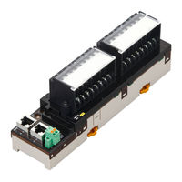
Omron DeviceNet XWT-OD08 User Manual (394 pages)
GX-series, EtherCAT Remote I/O Terminal EtherCAT Slave Units
Brand:
Omron
| Category:
Touch terminals
| Size: 8.79 MB
Table of Contents
Icon
7
Structure of this Manual
9
Terms and Conditions Agreement
9
Application Considerations
10
Safety Precautions
11
Precautions for Safe Use
14
Precautions for Correct Use
16
Regulations and Standards
17
Conformance to UL and CSA Standards
18
Related Manuals
20
Version Upgrade Information
20
Table of Contents
22
Section 1 Ethercat Network
28
Overview of Ethercat Networks
28
Features of Ethercat
28
Structure of Ethercat
28
Communications Types of Ethercat
30
Connection Examples of Ethercat
31
Configuration Elements of Ethercat Network
32
Configuration Devices of Ethercat Network
32
Overview of Configuration Devices
33
Ethercat Slave Unit
35
Section 2 Ethercat Slave Unit
36
Overview of Ethercat Slave Unit
36
Slave Units Usage
36
Features of GX-Series Ethercat Slave Units
36
Types of Ethercat Slave Units
37
Slave Units List
37
Installation, I/O Connection, and Power Supply Methods for each Slave Unit
40
Basic Usage Procedures
44
Setup Examples and Basic Procedure
44
System Setting Examples
44
Basic Procedure
45
Setting and Wiring Hardware
46
Mounting and Setting Ethercat Master Unit
46
Mounting and Setting Slave Units
46
Wiring Communications Cables
46
Connecting Power Supplies
46
Wiring I/O Devices
46
Starting Communications
47
Starting a System
47
Setting Ethercat Communications
47
Starting Ethercat Communications
47
Checking Operations
48
Checking Unit Displays
48
Confirming Data Read and Write
48
Setting Slave Unit Parameter
48
Installation and Wiring
49
Mounting Slave Units
50
Mounting Preparation
50
Mounting Direction
50
Mounting Method
50
Removal Method
51
Connecting to Ethercat Network
52
Precautions for Network Connection
52
Preparation for Connecting Network
53
Connecting Communications Cables and Connectors
54
Connecting to Communications Cables
55
Connecting to Unit Power Supply and I/O Power Supply
56
Precautions at Supplying Unit Power and I/O Power
56
Unit Power Supply Specifications
57
Connecting the Unit Power Supply
57
Connecting the I/O Power Supply
59
Connecting an External Device
61
Connecting to a Screw Terminal Block
61
Connecting to E-CON Connector Terminals
62
Connecting the M12 Connector
65
Ethercat Communications
67
Structure of CAN Application Protocol over Ethercat (Coe)
68
Ethercat Slave Information File (ESI File)
69
Communications State Transitions
70
Process Data Objects (PDO)
71
Overview
71
PDO Mapping Settings
71
Sync Manager PDO Assignment Settings
72
Fixed PDO Mapping
73
Service Data Object (SDO)
76
Overview
76
Abort Codes
76
Ethercat Master Unit - Slave Unit Communications
77
FREE RUN Mode
77
DC Mode
77
Emergency Messages
79
Emergency Message Notification
79
Diagnosis History
80
Sysmac Device Functions
81
Section 6 Basic Specifications of Slave Units
86
Ethercat Communications Specifications
86
General Specifications
87
Specifications of Common Areas
88
Status Indicators
88
Node Address Setting Switches
90
Communications Connectors
92
Unit Power Supply Connector
95
I/O Power Supply Connector
97
Digital I/O Slave Unit
99
Digital I/O Slave Unit
100
7-1 Digital I/O Slave Unit
101
Section 7 Digital I/O Slave Unit
101
I/O Data Allocation (PDO Mapping)
101
Input Data Allocation
101
Output Data Allocation
103
Functions of Digital I/O Slave Units
105
Input Filter
105
Error Mode Output
106
Specifications for each Slave Unit
107
2-Tier Terminal Block Type 16-Point Input Slave Unit GX-ID1611/ID1621
108
2-Tier Terminal Block Type 16-Point Output Slave Unit GX-OD1611/OD1621
112
2-Tier Terminal Block Relay Type 16-Point Output Slave Unit GX-OC1601
116
2-Tier Terminal Block Type 8-Point Input and 8-Point Output Slave Unit GX-MD1611/MD1621
120
3-Tier Terminal Block Type 16-Point Input Slave Unit GX-ID1612/ID1622
126
3-Tier Terminal Block Type 16-Point Output Slave Unit GX-OD1612/OD1622
131
3-Tier Terminal Block Type 8-Point Input and 8-Point Output Slave Unit GX-MD1612/MD1622
136
E-CON Connector Type 16-Point Input Slave Unit GX-ID1618/ID1628
142
E-CON Connector Type 16-Point Output Slave Unit GX-OD1618/OD1628
146
E-CON Connector Type 8-Point Input and 8-Point Output Slave Unit
151
Gx-Md1618/Md1628
151
E-CON Connector Type 32-Point Input Slave Unit GX-ID3218/ID3228
157
E-CON Connector Type 32-Point Output Slave Unit GX-OD3218/OD3228
162
Gx-Md3218/Md3228
167
E-CON Connector Type 16-Point Input and 16-Point Output Slave Unit GX-MD3218/MD3228
167
Mounting Dimensions
173
2-Tier Terminal Block Type
173
3-Tier Terminal Block Type
174
E-CON Connector Type
175
Analog I/O Slave Unit
179
Analog I/O Slave Unit
180
8-1 Analog I/O Slave Unit
181
Section 8 Analog I/O Slave Unit
181
Overview of the Analog Input Slave Unit
181
Input Range and Converted Data
181
I/O Data Allocation (PDO Mapping)
184
Function of the Analog Input Slave Unit
185
AD Conversion Available Point Setting
185
Moving Average
186
Disconnected Line Detection
188
User Adjustment
188
Overview of the Analog Output Slave Unit
190
Output Range and Converted Data
190
I/O Data Allocation (PDO Mapping)
192
Function of the Analog Output Slave Unit
193
DA Conversion Available Point Setting
193
Analog Output Fault Action
194
User Adjustment
195
Overview of each Slave Unit Type
196
4-Point Input Slave Unit GX-AD0471
197
2-Point Output Slave Unit GX-DA0271
201
Mounting Dimensions
205
Encoder Input Slave Unit
208
9-1 Encoder Input Slave Unit
209
I/O Data Allocation
209
Input Data Allocation
209
Output Data Allocation
212
Function of the Encoder Input Slave Units
214
Count Mode
214
Circular Counter
214
Input Signal Types
215
Encoder Direction Setting
217
Counter Reset
218
Counter Preset
219
Counter Value Latch
219
Specifications for each Slave Unit
220
Open Collector Input Type GX-EC0211
221
Line Driver Input Type GX-EC0241
229
Mounting Dimensions
236
IO-Link Master Unit
237
What Is an IO-Link Master Unit
238
Introduction
238
Devices
238
Support Software to be Used
239
I/O Data Allocations: PDO Mapping
240
Allocating Input Data
240
Allocating Output Data
242
Functions of the IO-Link Master Unit
243
Specifications
245
Part Names and Functions
249
Mounting Dimensions
253
Communications Performance
254
Maximum I/O Response Time
254
Determining the IO-Link Communications Cycle
256
Connected Device Specifications and Models
257
Expansion Unit
261
Section 11 Expansion Unit
262
Overview of the Expansion Unit
262
Connecting Expansion Units
262
I/O Power Supply
263
Specifications of Expansion Unit
264
Point Input Expansion Unit XWT-ID08/ID08-1
265
Point Output Expansion Unit XWT-OD08/OD08-1
268
Point Input Expansion Unit XWT-ID16/ID16-1
271
Point Output Expansion Unit XWT-OD16/OD16-1
275
Mounting Dimensions
279
Section 12 Troubleshooting and Maintenance
282
Troubleshooting
282
Errors that Can be Checked with Status Indicator and Actions to Take
282
Errors Unique to each Slave Unit
287
Error Notification Methods and Types
293
Sysmac Error Status Codes
294
Emergency Error Code
299
Application Layer Status Codes
301
Equipment Maintenance
303
Cleaning
303
Inspections
303
Handling When Replacing Units
304
Replacing the IO-Link Master Unit or IO-Link Devices
304
Appendix
305
Object Dictionary
306
A-1-1 Object Dictionary Area
306
A-1-2 Data Types
306
A-1-3 Object Description Format
307
A-1-4 Communication Objects
308
A-1-5 PDO Mapping Object
314
A-1-6 Sync Manager Communication Object
330
Digital I/O Slave Unit
332
Analog I/O Slave Unit
332
Encoder Input Slave Unit
332
IO-Link Master Unit
333
Expansion Unit
334
A-1-7 Manufacturer Specific Objects
336
Voltage
352
Current Consumption Summary
378
A-2-1 Digital I/O Slave Unit
378
A-2-2 Analog I/O Slave Unit
378
A-2-3 Encoder Input Slave Unit
378
A-2-4 IO-Link Master Unit
379
A-2-5 Expansion Unit
379
Precautions with Connecting Two-Wire DC Sensors
380
A-3-1 Relation between on Voltage of a Unit with DC Inputs and Sensor Residual Voltage
380
A-3-2 Relation between on Current of a Unit with DC Inputs and Sensor Control Output
380
Current
380
A-3-3 Relation between off Current of a Unit with DC Inputs and Sensor Leakage Current
381
Wiring External Output Signal Lines
382
I/O Power Supply Current
383
Glossary
385
Version Information
387
Index
389
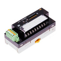
Omron DeviceNet XWT-OD08 Operation Manual (282 pages)
DeviceNet Slaves
Brand:
Omron
| Category:
Industrial Electrical
| Size: 6.52 MB
Table of Contents
Precautions
10
Table of Contents
10
Intended Audience
11
General Precautions
12
Safety Precautions
13
Operating Environment Precautions
14
Application Precautions
15
EC Directives
17
Section 1 Smart Slaves and Features
18
DRT2 Features
19
Overview
19
Features
19
DRT2 Slaves
23
General-Purpose Slaves
23
Environment-Resistive Slaves
23
Analog Slaves
23
Smart Slave Feature Support
24
Installing and Connecting Slaves
25
Section 2 Example System Startup
28
Basic Procedures and Configuration Examples
29
Basic Procedures
29
System Configuration Example
29
Preparations
30
Selecting Units
30
Wiring
30
Communications Power Supply
30
Setting and Wiring Hardware
31
Mounting and Setting the Master Unit
31
Mounting and Setting Slaves
32
Mounting Connecting Devices
33
Connecting Cables
33
Starting Communications
34
Creating I/O Tables for the Master Unit
34
Starting the System
34
Creating and Registering Scan Lists
35
Checking Operation
36
Indicator Status
36
Reading and Writing Data
36
Section 3 Common Slave Specifications
38
Common Slave Specifications
39
Communications Specifications
39
MS and NS Indicators
39
Devicenet Remote I/O Communications
41
Overview of Remote I/O Allocations for Smart Slaves
41
I/O Allocations for Smart Slaves
43
I/O Allocation with the Configurator (Ver. 2.@ or Later)
47
Section 4 Functions
54
Maintenance Mode Window and Main Window
55
Maintenance Mode Window
55
Common Slave Functions
56
Automatic Baud Rate Recognition
56
Network Power Supply Voltage Monitor
57
Unit Conduction Time Monitor
58
Slave Comments
59
I/O Comments
61
Communications Error History Monitor
63
Last Maintenance Date
64
Remote I/O Terminal and Environment-Resistive Terminal Functions
65
I/O Power Status Monitor
65
Input Filter
66
Power on Delay
68
Contact Operation Counter
68
Total on Time Monitor
70
Operation Time Monitor (Remote I/O Terminals Only)
72
Sensor Disconnected Detection (Environment-Resistive Terminal Input Units Only)
75
Detection of Sensor Power Short-Circuit (Environment-Resistive Terminal Input Units Only)
76
External Load Short-Circuit Detection (Environment-Resistive Terminal Output Units Only)
78
Section 5 General-Purpose Slaves
82
Common Specifications for General-Purpose Slaves
83
Current Consumption and Weights
83
Connecting Communications Cables to General-Purpose Slaves
84
Connecting Communications Cables
84
Connecting Communications Cables to the Nodes
86
Mounting Terminating Resistors
87
Remote I/O Terminals with Transistors
88
Node Address, Baud Rate, and Output Hold/Clear Settings
88
Increasing I/O Using an Expansion Unit
90
Remote I/O Terminals with Transistors and 16 Inputs: DRT2-ID16 (NPN) and DRT2-ID16-1 (PNP)
92
Remote I/O Terminals with Transistors and 16 Outputs: DRT2-OD16 (NPN) and DRT2-OD16-1 (PNP)
94
XWT-ID08 (NPN) and XWT-ID08-1 (PNP)
97
XWT-ID16 (NPN) and XWT-ID16-1 (PNP)
100
Remote I/O Terminal Expansion Units with Transistors and 8 Outputs:
103
Remote I/O Terminal Expansion Units with Transistors and 16 Outputs:
105
Mounting in Control Panels
108
5-3-10 Wiring the I/O Power Supply and I/O Lines
108
Section 6 Environment-Resistive Slaves
110
Common Specifications for Environment-Resistive Slaves
111
Current Consumption, Weight, Enclosure Ratings
111
I/O Indicators
111
Connecting Communications Cables to Environment-Resistive Slaves
112
System with Slaves Using Round Connectors Only
112
System with Slaves Using Round Connectors and Regular Square Connectors
113
Communications Cables for Environment-Resistive Terminals
113
Example System Assembly
115
Environment-Resistive Terminals
116
Node Address, Baud Rate, and Output Hold/Clear Settings
116
Environment-Resistive Terminals with 8 Transistor Inputs (IP67): DRT2-ID08C (NPN) and DRT2-ID08C-1 (PNP)
116
Environment-Resistive Terminals with 16 Transistor Inputs (IP67): DRT2-HD16C (NPN) and DRT2-HD16C-1 (PNP)
121
Environment-Resistive Terminals with 8 Transistor Outputs (IP67): DRT2-OD08C (NPN) and DRT2-OD08C-1 (PNP)
126
Mounting in Control Panels
131
Wiring the Internal Power Supply, I/O Power Supply, and I/O Lines
132
Section 7 Analog Slaves
136
Overview of Analog Slaves
137
DRT2 Analog Slaves
137
Comparison of DRT1 and DRT2 Functions
137
List of Data Processing Functions
139
Analog Data Operation Flowcharts (Analog Input Terminals)
140
Selecting Analog Data (Analog Input Terminals)
140
I/O Data Allocated in the Master
141
Allocating I/O Data in the Master
143
Procedure for Allocating I/O in the Master
145
Application Procedure Flowchart
146
Common Procedures
147
Connecting Communications Cables
147
Node Address and Baud Rate Settings
147
Mounting in Control Panels
148
Wiring the I/O Lines
149
Analog Input Terminals
149
DRT2-AD04 Analog Input Terminals
149
I/O Data Allocation Methods
155
Functions and Settings
165
Calculating the Conversion Cycle
187
Analog Output Terminals
188
DRT2-DA02 Analog Output Terminal
188
I/O Data Types and Allocation Methods
193
Functions and Setting Methods
198
Section 8 Communications Timing
208
Remote I/O Communications Characteristics
209
I/O Response Time
209
Communications Cycle Time and Refresh Time
214
More than One Master in Network
216
System Startup Time
217
Message Communications Characteristics
218
Message Communications Time
218
Section 9 Troubleshooting and Maintenance
220
Indicators and Error Processing
221
Error Occurring in the Slave Unit
221
Troubleshooting
222
Slave Unit Troubleshooting
222
Maintenance
224
Cleaning
224
Inspection
225
Replacing Units
225
Advertisement
Advertisement
Related Products
OMRON DeviceNet XWT-ID08
OMRON DeviceNet XWT-ID16
Omron DeviceNet XWT-ID16-1
Omron DeviceNet XWT-OD16
Omron DeviceNet XWT-OD16-1
Omron DeviceNet XWT-ID08-1
Omron DeviceNet XWT-OD08-1
Omron XS6W-6LSZH8SS CM-Y Series
Omron XS5W-T421-MD-K Series
Omron XS5W-T421-MC-K Series
Omron Categories
Blood Pressure Monitor
Controller
Accessories
Switch
Inverter
More Omron Manuals
Login
Sign In
OR
Sign in with Facebook
Sign in with Google
Upload manual
Upload from disk
Upload from URL