Table of Contents
Advertisement
Quick Links
Advertisement
Table of Contents

Related Manuals for SMC Networks EliteConnect SMCE21011


Summary of Contents for SMC Networks EliteConnect SMCE21011
-
Page 1: User Guide
USER GUIDE SMCE21011 EliteConnect SMCE21011 802.11b/g/n AP... -
Page 2: Step
EliteConnect SMCE21011 User Guide April 2009 20 Mason Pub. # XXXXXXXXXXX Irvine, CA 92618 E042009-DT-R01 Phone: (949) 679-8000... - Page 3 Information furnished by SMC Networks, Inc. (SMC) is believed to be accurate and reliable. However, no responsibility is assumed by SMC for its use, nor for any infringements of patents or other rights of third parties which may result from its use. No license is granted by implication or otherwise under any patent or patent rights of SMC.
-
Page 4: Limited Warranty
IMITED ARRANTY Limited Warranty Statement: SMC Networks, Inc. (“SMC”) warrants its products to be free from defects in workmanship and materials, under normal use and service, for the applicable warranty term. All SMC products carry a standard 90-day limited warranty from the date of purchase from SMC or its Authorized Reseller. - Page 5 SMC price list. Under the limited lifetime warranty, internal and external power supplies, fans, and cables are covered by a standard one-year warranty from date of purchase. SMC Networks, Inc. 20 Mason Irvine, CA 92618 – 5 –...
- Page 6 – 6 –...
-
Page 7: Compliances
OMPLIANCES EDERAL OMMUNICATION OMMISSION NTERFERENCE TATEMENT This equipment has been tested and found to comply with the limits for a Class B digital device, pursuant to Part 15 of the FCC Rules. These limits are designed to provide reasonable protection against harmful interference in a residential installation. - Page 8 BOUT UIDE IMPORTANT NOTE: FCC R ADIATION XPOSURE TATEMENT This equipment complies with FCC radiation exposure limits set forth for an uncontrolled environment. This equipment should be installed and operated with minimum distance 20 cm between the radiator & your body. IC S TATEMENT This Class B digital apparatus complies with Canadian ICES-003.
- Page 9 BOUT UIDE AS/NZS 4771 USTRALIA EALAND ACN 066 352010 VCCI C APAN LASS AIWAN 根據交通部低功率管理辦法規定: 第十二條 經型式認證合格之低功率射頻電機,非經許可,公司、商號或使用者均不得擅自變更 頻率、加大功率或變更原設計之特性及功能。 第十四條 低功率射頻電機之使用不得影響飛航安全及干擾合法通信;經發現有干擾現象時,應 立即停用,並改善至無干擾時方得繼續使用。前項合法通信,指依電信法規定作業之無線電通 信。低功率射頻電機須忍受合法通信或工業、科學及醫療用電波輻射性電機設備之干擾。 EC C ONFORMANCE ECLARATION Marking by the above symbol indicates compliance with the Essential Requirements of the R&TTE Directive of the European Union (1999/5/EC). This equipment meets the following conformance standards: EN 60950-1 (IEC 60950-1) - Product Safety ◆...
- Page 10 BOUT UIDE In Italy the end-user must apply for a license from the national ◆ spectrum authority to operate this device outdoors. In Belgium outdoor operation is only permitted using the 2.46 - 2.4835 ◆ GHz band: Channel 13. In France outdoor operation is only permitted using the 2.4 - 2.454 GHz ◆...
- Page 11 BOUT UIDE In Italy the end-user must apply for a license from the national ◆ spectrum authority to operate this device outdoors. In Belgium outdoor operation is only permitted using the 2.46 - ◆ 2.4835 GHz band: Channel 13. In France outdoor operation is only permitted using the 2.4 - 2.454 ◆...
- Page 12 BOUT UIDE Swedish Härmed intygar SMC att denna Radio LAN device står I överensstämmelse med de väsentliga egenskapskrav och övriga relevanta bestämmelser som framgår av direktiv Svenska 1999/5/EG. Danish Undertegnede SMC erklærer herved, at følgende udstyr Radio LAN device overholder de væsentlige krav og øvrige relevante krav i direktiv 1999/5/EF Dansk German...
-
Page 13: About This Guide
BOUT UIDE This guide gives specific information on how to install the 11n wireless URPOSE access point and its physical and performance related characteristics. It also gives information on how to operate and use the management functions of the access point. This guide is intended for use by network administrators who are UDIENCE responsible for installing, operating, and maintaining network equipment;... -
Page 14: Table Of Contents
ONTENTS IMITED ARRANTY OMPLIANCES BOUT UIDE ONTENTS IGURES ABLES CLI C NDEX OF OMMANDS ECTION ETTING TARTED NTRODUCTION Key Hardware Features Description of Capabilities Package Contents Hardware Description Antennas External Antenna Connector LED Indicators Console Port Ethernet Port Power Connector Reset Button ETWORK OPOLOGIES... - Page 15 ONTENTS NSTALLING THE ACCESS POINT Location Selection Mounting on a Horizontal Surface Mounting on a Wall Connecting and Powering On NITIAL ONFIGURATION Connecting to the Login Page Home Page and Main Menu Common Web Page Buttons Quick Start Step 1 Step 2 Step 3 Main Menu Items...
- Page 16 ONTENTS SNMP Basic Settings SNMP Trap Settings View Access Control Model SNMPv3 Users SNMPv3 Targets SNMPv3 Notification Filters DVANCED ETTINGS Local Bridge Filter Link Layer Discovery Protocol Access Control Lists Source Address Settings Destination Address Settings Ethernet Type IRELESS ETTINGS Spanning Tree Protocol (STP) Bridge Ethernet Interface...
- Page 17 ONTENTS AP System Configuration AP Wireless Configuration Station Status System Logs ECTION OMMAND NTERFACE 11 U SING THE OMMAND NTERFACE Console Connection Telnet Connection Entering Commands Keywords and Arguments Minimum Abbreviation Command Completion Getting Help on Commands Showing Commands Negating the Effect of Commands Using Command History Understanding Command Modes Exec Commands...
- Page 18 ONTENTS 21 MAC A DDRESS UTHENTICATION OMMANDS 22 F ILTERING OMMANDS 23 S PANNING OMMANDS 24 WDS B RIDGE OMMANDS 25 E THERNET NTERFACE OMMANDS 26 W IRELESS NTERFACE OMMANDS 27 W IRELESS ECURITY OMMANDS 28 L AYER ISCOVERY OMMANDS 29 VLAN C OMMANDS 30 WMM C...
-
Page 19: Figures
IGURES Figure 1: Top Panel Figure 2: Rear Panel Figure 3: Ports Figure 4: External Antenna Connector Figure 5: Screw-off External Antenna Connector - Close Up Figure 6: LEDs Figure 7: Infrastructure Wireless LAN Figure 8: Infrastructure Wireless LAN for Roaming Wireless PCs Figure 9: Bridging Mode Figure 10: Attach Feet Figure 11: Wall Mounting... - Page 20 IGURES Figure 32: SNMP VACM Figure 33: Configuring SNMPv3 Users Figure 34: SNMPv3 Targets Figure 35: SNMP Notification Filter Figure 36: Local Bridge Filter Figure 37: LLDP Settings Figure 38: Source ACLs Figure 39: Destination ACLs Figure 40: Ethernet Type Filter Figure 41: Spanning Tree Protocol Figure 42: Local Authentication Figure 43: RADIUS Authentication...
-
Page 21: Tables
ABLES Table 1: Key Hardware Features Table 2: LED Behavior Table 3: RADIUS Attributes Table 4: Logging Levels Table 5: WMM Access Categories Table 6: Command Modes Table 7: Keystroke Commands Table 8: General Commands Table 9: System Management Commands Table 10: Country Codes Table 11: System Management Commands Table 12: Logging Levels... - Page 22 ABLES Table 32: 10/100BASE-TX MDI and MDI-X Port Pinouts Table 33: 1000BASE-T MDI and MDI-X Port Pinouts Table 34: 10/100BASE-TX MDI and MDI-X Port Pinouts – 22 –...
-
Page 23: Ndex Of Cli Commands
CLI C NDEX OF OMMANDS 802.1x enable 175 interface wireless 802.1x session-timeout 176 interface-radio-mode 205 address filter default 177 ip address address filter delete ip dhcp 197 address filter entry 178 ip http port a-mpdu ip http server a-msdu ip https port APmgmtIP ip https server APmgmtUI... - Page 24 CLI C NDEX OF OMMANDS show bridge br-conf show bridge forward address show bridge port-conf show bridge status show bridge stp show config show dhcp-relay show dual-image show event-log show filters show hardware 142 show history show interface ethernet show interface wireless show line show lldp show logging 146...
- Page 25 CLI C NDEX OF OMMANDS – 25 –...
-
Page 26: Ection
ECTION ETTING TARTED This section provides an overview of the access point, and introduces some basic concepts about wireless networking. It also describes the basic settings required to access the management interface. This section includes these chapters: “Introduction” on page 27 ◆... -
Page 27: Key Hardware Features
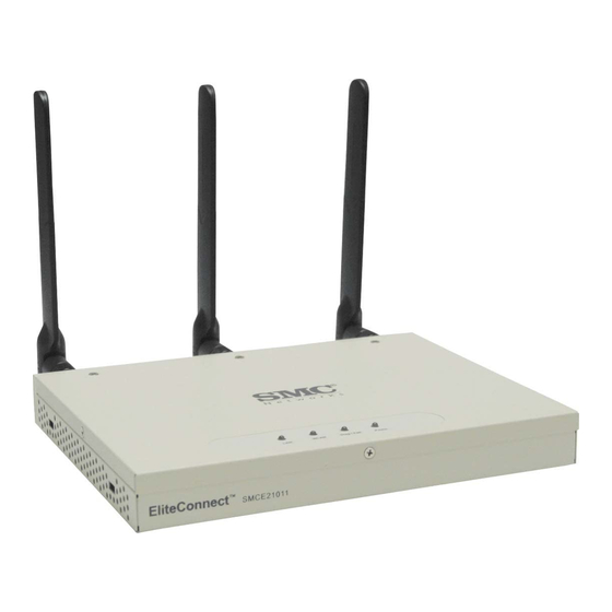
NTRODUCTION The EliteConnect SMCE21011 is an IEEE 802.11n access point (AP) that meets draft 2.0 standards. It is fully interoperable with older 802.11a/b/g standards, providing a transparent, wireless high speed data communication between the wired LAN and fixed or mobile devices. The unit includes three detachable dual-band 2.4/5 GHz antennas with the option to attach higher specification external antennas that boost network coverage. -
Page 28: Package Contents
| Introduction HAPTER Package Contents In addition, the access point offers full network management capabilities through an easy to configure web interface, a command line interface for initial configuration and troubleshooting, and support for Simple Network Management tools. The SMCE21011 utilises MIMO technology and Spatial Multiplexing to achieve the highest possible data rate and throughput on the 802.11n frequency. -
Page 29: Hardware Description
| Introduction HAPTER Hardware Description ARDWARE ESCRIPTION Figure 1: Top Panel Antennas LED Indicators Figure 2: Rear Panel Reset Button DC Power Port RJ-45 PoE Port – 29 –... -
Page 30: Antennas
| Introduction HAPTER Hardware Description Figure 3: Ports RJ-45 Console Port DC Power Port RJ-45 PoE Port The access point includes three integrated external MIMO (multiple-input NTENNAS and multiple-output) antennas. MIMO uses multiple antennas for transmitting and receiving radio signals to improve data throughput and link range. -
Page 31: Figure 4: External Antenna Connector
| Introduction HAPTER Hardware Description Figure 4: External Antenna Connector Figure 5: Screw-off External Antenna Connector - Close Up – 31 –... -
Page 32: Led Indicators
| Introduction HAPTER Hardware Description The access point includes four status LED indicators, as described in the LED I NDICATORS following figure and table. Figure 6: LEDs 802.11 b/g/n Ethernet Power 802.11 a/n Indicator Link/Activity Indicator Table 2: LED Behavior Status Description The 802.11a/n radio is disabled. -
Page 33: Console Port
| Introduction HAPTER Hardware Description Table 2: LED Behavior (Continued) Status Description POWER Indicates that there is no power or the power source has been disconnected. Flashing Green Indicates that the system is rebooting or has started a reset. Green Indicates that power is being supplied and the system is functioning normally. -
Page 34: Reset Button
| Introduction HAPTER Hardware Description The access point supports both endspan and midspan PoE. If the access point is connected to a PoE source device and also connected to a local power source through the AC power adapter, AC power will be disabled. -
Page 35: Network Topologies
ETWORK OPOLOGIES Wireless networks support a standalone configuration as well as an integrated configuration with 10/100/1000 Mbps Ethernet LANs. The SMCE21011 also provides bridging services that can be configured independently on either the 5 GHz or 2.4 GHz radio interfaces. Access points can be deployed to support wireless clients and connect wired LANs in the following configurations: Infrastructure for wireless LANs... -
Page 36: Infrastructure Wireless Lan For Roaming Wireless Pcs
| Network Topologies HAPTER Infrastructure Wireless LAN for Roaming Wireless PCs The infrastructure configuration extends the accessibility of wireless PCs to the wired LAN. A wireless infrastructure can be used for access to a central database, or for connection between mobile workers, as shown in the following figure. Figure 7: Infrastructure Wireless LAN Wired LAN Extension to Wireless Clients... -
Page 37: Infrastructure Wireless Bridge
| Network Topologies HAPTER Infrastructure Wireless Bridge coverage area is created, wireless users within this ESS can roam freely. All wireless network cards and adapters and wireless access points within a specific ESS must be configured with the same SSID. Figure 8: Infrastructure Wireless LAN for Roaming Wireless PCs Seamless Roaming Between Access Points... -
Page 38: Figure 9: Bridging Mode
| Network Topologies HAPTER Infrastructure Wireless Bridge Figure 9: Bridging Mode WDS Links Network Between Access Points Core VAP 0 WDS AP Mode VAP 2 WDS AP Mode VAP 0 VAP 1 WDS STA Mode WDS AP Mode VAP 2 WDS STA Mode VAP 1 WDS AP Mode... -
Page 39: Installing The Access Point
NSTALLING THE ACCESS POINT This chapter describes how to install the access point. OCATION ELECTION Choose a proper place for the access point. In general, the best location is at the center of your wireless coverage area, within line of sight of all wireless devices. -
Page 40: Mounting On A Horizontal Surface
| Installing the access point HAPTER Mounting on a Horizontal Surface OUNTING ON A ORIZONTAL URFACE To keep the access point from sliding on the surface, attach the four rubber feet provided in the accessory kit to the marked circles on the bottom of the access point. -
Page 41: Mounting On A Wall
| Installing the access point HAPTER Mounting on a Wall OUNTING ON A To mount on a wall follow the instructions below. Figure 11: Wall Mounting Mounting Slots The access point should be mounted only to a wall or wood surface that is at least 1/2-inch plywood or its equivalent. -
Page 42: Connecting And Powering On
| Installing the access point HAPTER Connecting and Powering On ONNECTING AND OWERING Connect the power adapter to the access point, and the power cord to an AC power outlet. Otherwise, the access point can derive its operating power directly from the RJ-45 port when connected to a device that provides IEEE 802.3af compliant Power over Ethernet (PoE). -
Page 43: Initial Configuration
NITIAL ONFIGURATION The SMCE21011 offers a user-friendly web-based management interface for the configuration of all the unit’s features. Any PC directly attached to the unit can access the management interface using a web browser, such as Internet Explorer (version 6.0 or above). ONNECTING TO THE OGIN It is recommended to make initial configuration changes by connecting a... -
Page 44: Home Page And Main Menu
| Initial Configuration HAPTER Home Page and Main Menu AGE AND After logging in to the web interface, the Home page displays. The Home page shows some basic settings for the AP, including Country Code and the management access password. Figure 13: Home Page The web interface Main Menu menu provides access to all the configuration settings available for the access point. -
Page 45: Common Web Page Buttons
| Initial Configuration HAPTER Common Web Page Buttons You must set the country code to the country of operation. AUTION Setting the country code restricts operation of the access point to the radio channels and transmit power levels permitted for wireless networks in the specified country. -
Page 46: Quick Start
| Initial Configuration HAPTER Quick Start Logout – Ends the web management session. ◆ Save Config – Saves the current configuration so that it is retained ◆ after a restart. UICK TART The Quick Start menu is designed to help you configure the basic settings required to get the access point up and running. -
Page 47: Figure 17: Quick Start - Step 2
| Initial Configuration HAPTER Quick Start HANGE ASSWORD Username — The name of the user, non-configurable. ◆ (Default: accton) Old Password — If the unit has been configured with a password ◆ already, enter that password, otherwise enter a null string. New Password —... - Page 48 | Initial Configuration HAPTER Quick Start The following items are displayed on this page: DHCP DHCP Status — Enables/disables DHCP on the access point. (Default: ◆ disabled) ◆ IP Address — Specifies an IP address for management of the access point.
-
Page 49: Step
| Initial Configuration HAPTER Quick Start The Step 3 page of the Quick Start configures radio interface settings. Figure 18: Quick Start - Step 3 The following items are displayed on this page: NTERFACE ETTING WiFi Mode — Selects mode of operation of the radio chip from ◆... -
Page 50: Main Menu Items
| Initial Configuration HAPTER Main Menu Items UTHENTICATION 802.1x — Enables 802.1x authentication. (Default: Enabled) ◆ ◆ 802.1x Reauthentication Refresh Rate — Sets the reauthentication refresh rate for 802.1x authentication. (Default: 3600 seconds; Range: 1-65535 seconds; 0=disabled) RADIUS — If configuring a RADIUS server refer to the section ◆... -
Page 51: Ection
ECTION ONFIGURATION This section provides details on configuring the access point using the web browser interface. This section includes these chapters: “System Settings” on page 52 ◆ “Management Settings” on page 65 ◆ “Advanced Settings” on page 76 ◆ ◆ “Wireless Settings”... -
Page 52: System Settings
YSTEM ETTINGS This chapter describes basic system settings on the access point. It includes the following sections: ◆ “Administration Settings” on page 52 “IP Address” on page 54 ◆ “Radius Settings” on page 55 ◆ “System Time” on page 58 ◆... -
Page 53: Figure 19: Administration
| System Settings HAPTER Administration Settings Figure 19: Administration The following items are displayed on this page: System Name — An alias for the access point, enabling the device to ◆ be uniquely identified on the network. (Default: SMC; Range: 1-32 characters) ◆... -
Page 54: Ip Address
| System Settings HAPTER IP Address IP A DDRESS Configuring the access point with an IP address expands your ability to manage the access point. A number of access point features depend on IP addressing to operate. You can use the web browser interface to access IP addressing only if the access point already has an IP address that is reachable through your network. -
Page 55: Radius Settings
| System Settings HAPTER Radius Settings DHCP Status — Enables/disables DHCP on the access point. ◆ IP Address — Specifies an IP address for management of the access ◆ point. Valid IP addresses consist of four decimal numbers, 0 to 255, separated by periods. -
Page 56: Primary And Secondary Radius Server Setup
| System Settings HAPTER Radius Settings A primary RADIUS server must be specified for the access point to RIMARY AND implement IEEE 802.1X network access control and Wi-Fi Protected Access RADIUS ECONDARY (WPA) wireless security. A secondary RADIUS server may also be specified ERVER ETUP as a backup should the primary server fail or become inaccessible. -
Page 57: Figure 23: Radius Settings
| System Settings HAPTER Radius Settings Figure 23: RADIUS Settings The following items are displayed on the RADIUS Settings page: RADIUS Status — Enables/disables the primary RADIUS server. ◆ IP Address — Specifies the IP address or host name of the RADIUS ◆... -
Page 58: Radius Accounting
| System Settings HAPTER System Time The following items are displayed on the RADIUS Settings page: RADIUS A CCOUNTING Account Status — Enables/disables RADIUS accounting. ◆ IP Address — Specifies the IP address or host name of the RADIUS ◆ accounting server. -
Page 59: Sntp Server Settings
| System Settings HAPTER System Time Figure 24: SNTP Settings The following items are displayed on this page: Configures the access point to operate as an SNTP client. When enabled, at SNTP S ERVER least one time server IP address must be specified. ETTINGS SNTP Status —... -
Page 60: Daylight Saving Settings
| System Settings HAPTER SpectraLink Voice Priority The access point provides a way to automatically adjust the system clock AYLIGHT AVING for Daylight Savings Time changes. To use this feature you must define the ETTINGS month and date to begin and to end the change from standard time. During this period the system clock is set back by one hour. - Page 61 | System Settings HAPTER VLAN Configuration The management VLAN is for managing the access point through ◆ remote management tools, such as the web interface, SSH, SNMP, or Telnet. The access point only accepts management traffic that is tagged with the specified management VLAN ID. All wireless clients associated to the access point are assigned to a ◆...
-
Page 62: System Logs
| System Settings HAPTER System Logs Table 3: RADIUS Attributes Number RADIUS Attribute Value Tunnel-Type VLAN (13) Tunnel-Medium-Type Tunnel-Private-Group-ID VLANID (1 to 4094 as hexadecimal or string) VLAN IDs on the RADIUS server can be entered as hexadecimal digits or a string The specific configuration of RADIUS server software is beyond the scope of this guide. -
Page 63: Figure 27: System Log Settings
| System Settings HAPTER System Logs Figure 27: System Log Settings The following items are displayed on this page: syslog status — Enables/disables the logging of error messages. ◆ (Default: enabled) Server 1~4 — Enables the sending of log messages to a Syslog server ◆... -
Page 64: Quick Start Wizard
| System Settings HAPTER Quick Start Wizard severe (Debug). The message levels that are logged include the specified minimum level up to the Emergency level. Table 4: Logging Levels Error Level Description Emergency System unusable Alerts Immediate action needed Critical Critical conditions (e.g., memory allocation, or free memory error - resource exhausted) Error Error conditions (e.g., invalid input, default used) -
Page 65: Management Settings
ANAGEMENT ETTINGS This chapter describes management access settings on the access point. It includes the following sections: ◆ “Remote Management Settings” on page 65 “Access Limitation” on page 67 ◆ “Simple Network Management Protocol” on page 68 ◆ EMOTE ANAGEMENT ETTINGS The Web, Telnet, and SNMP management interfaces are enabled and open to all IP addresses by default. -
Page 66: Figure 28: Remote Management
| Management Settings HAPTER Remote Management Settings The client and server generate session keys for encrypting and ◆ decrypting data. The client and server establish a secure encrypted connection. ◆ A padlock icon should appear in the status bar for Internet Explorer 5.x. ◆... -
Page 67: Access Limitation
| Management Settings HAPTER Access Limitation HTTP Port — Specifies the HTTP port for IP connectivity. (Default: 80; ◆ Range 1024-65535) HTTPS Server — Enables/disables management access from a HTTPS ◆ server. (Default: enabled) HTTPS Port — Specifies the HTTPS port for secure IP connectivity. ◆... -
Page 68: Simple Network Management Protocol
| Management Settings HAPTER Simple Network Management Protocol IP Address — Specifies the IP address. ◆ Subnet Mask — Specifies the subnet mask in the form 255.255.255.x ◆ ESTRICT ANAGEMENT Enable/Disable — Enables/disables management of the device by a ◆ wireless client. -
Page 69: Figure 30: Snmp Basic Settings
| Management Settings HAPTER Simple Network Management Protocol Figure 30: SNMP Basic Settings The following items are displayed on this page: SNMP — Enables or disables SNMP management access and also ◆ enables the access point to send SNMP traps (notifications). (Default: Disable) System Location —... -
Page 70: Snmp Trap Settings
| Management Settings HAPTER Simple Network Management Protocol Traps indicating status changes are issued by the AP to specified trap SNMP T ETTINGS managers. You must specify trap managers so that key events are reported by the AP to your management station (using network management platforms). -
Page 71: View Access Control Model
| Management Settings HAPTER Simple Network Management Protocol affect. Clicking ‘OK’ returns to the home page. Changes will not be saved upon a reboot unless the running configuration file is saved. To configure SNMPv3 management access to the AP, follow these steps: CCESS ONTROL ODEL... - Page 72 | Management Settings HAPTER Simple Network Management Protocol Mask (option) – A hexadecimal value with each bit masking the ◆ corresponding ID in the MIB subtree. A “1” in the mask indicates an exact match and a “0” indicates a “wild card.” For example, a mask value of 0xFFBF provides a bit mask “1111 1111 1011 1111.”...
-
Page 73: Snmpv3 Users
| Management Settings HAPTER Simple Network Management Protocol The access point allows up to 10 SNMP v3 users to be configured. Each SNMP SERS SNMPv3 user is defined by a unique name. Users must be configured with a specific security level and assigned to a group. The SNMPv3 group restricts users to a specific read, write, or notify view. -
Page 74: Snmpv3 Targets
| Management Settings HAPTER Simple Network Management Protocol An SNMP v3 notification Target ID is specified by the SNMP v3 user, IP SNMP ARGETS address, and UDP port. A user-defined filter can also be assigned to specific targets to limit the notifications received to specific MIB objects. (Note that the filter must first be configured. -
Page 75: Figure 35: Snmp Notification Filter
| Management Settings HAPTER Simple Network Management Protocol Figure 35: SNMP Notification Filter The following items are displayed on this page: Filter ID — A user-defined name that identifies the filter. (Maximum ◆ length: 32 characters) Subtree — Specifies MIB subtree to be filtered. The MIB subtree must ◆... -
Page 76: Advanced Settings
DVANCED ETTINGS This chapter describes advanced settings on the access point. It includes the following sections: ◆ “Local Bridge Filter” on page 76 “Link Layer Discovery Protocol” on page 77 ◆ “Access Control Lists” on page 78 ◆ OCAL RIDGE ILTER The access point can employ network traffic frame filtering to control access to network resources and increase security. -
Page 77: Link Layer Discovery Protocol
| Advanced Settings HAPTER Link Layer Discovery Protocol Prevent Intra VAP client communication — When enabled, clients ◆ associated with a specific VAP interface cannot establish wireless communications with each other. Clients can communicate with clients associated to other VAP interfaces. Prevent Inter and Intra VAP client communication —... -
Page 78: Access Control Lists
| Advanced Settings HAPTER Access Control Lists Message Transmission Hold Time — Configures the time-to-live ◆ (TTL) value sent in LLDP advertisements as shown in the formula below. (Range: 2-10; Default: 4) The time-to-live tells the receiving LLDP agent how long to retain all information pertaining to the sending LLDP agent if it does not transmit updates in a timely manner. -
Page 79: Destination Address Settings
| Advanced Settings HAPTER Access Control Lists Figure 38: Source ACLs The following items are displayed on this page: ◆ SA Status — Enables network traffic with specific source MAC addresses to be filtered (dropped) from the access point. MAC Address — Specifies a source MAC address to filter, in the form ◆... -
Page 80: Ethernet Type
| Advanced Settings HAPTER Access Control Lists The following items are displayed on this page: DA Status — Enables/disables the destination address to be filtered. ◆ MAC Address — Specifies a destination MAC address to filter, in the ◆ form xx.xx.xx.xx.xx.xx. Action —... -
Page 81: Figure 40: Ethernet Type Filter
| Advanced Settings HAPTER Access Control Lists Figure 40: Ethernet Type Filter The following items are displayed on this page: Disabled — Access point does not filter Ethernet protocol types. ◆ ◆ Enabled — Access point filters Ethernet protocol types based on the configuration of protocol types in the filter table. -
Page 82: Wireless Settings
IRELESS ETTINGS This chapter describes wireless settings on the access point. It includes the following sections: ◆ “Spanning Tree Protocol (STP)” on page 82 “Authentication” on page 85 ◆ “Radio Settings” on page 89 ◆ “Virtual Access Points (VAPs)” on page 93 ◆... -
Page 83: Bridge
| Wireless Settings HAPTER Spanning Tree Protocol (STP) Figure 41: Spanning Tree Protocol Sets STP bridge link parameters. RIDGE The following items are displayed on the STP page: Spanning Tree Protcol — Enables/disables STP on the wireless ◆ bridge. (Default: Enabled) Priority —... -
Page 84: Ethernet Interface
| Wireless Settings HAPTER Spanning Tree Protocol (STP) numeric values indicate higher priority.) (Default:32768; Range: 0-65535) Max Age — The maximum time (in seconds) a device can wait without ◆ receiving a configuration message before attempting to reconfigure. All device ports (except for designated ports) should receive configuration messages at regular intervals. -
Page 85: Wireless Interface
| Wireless Settings HAPTER Authentication Sets STP settings for the radio interface. IRELESS NTERFACE Index — Describes the VAP in question. ◆ Link Path Cost — This parameter is used by the STP to determine the ◆ best path between devices. Therefore, lower values should be assigned to ports attached to faster media, and higher values assigned to ports with slower media. -
Page 86: Figure 42: Local Authentication
| Wireless Settings HAPTER Authentication Figure 42: Local Authentication The following items are displayed on Authentication page: MAC Authentication — Selects between, disabled, Local MAC authentication and RADIUS authentication. Local MAC — The MAC address of the associating station is compared ◆... -
Page 87: Radius Mac Authentication
| Wireless Settings HAPTER Authentication Add/Delete: Adds or deletes the specified MAC address and ■ permission setting into or from the local database. Permission: Select Allow to permit access or Deny to block access. ■ If Delete is selected, the specified MAC address entry is removed from the database. -
Page 88: Interface Mode
| Wireless Settings HAPTER Interface Mode make MAC authentication take effect — Applies the specified ◆ settings. NTERFACE The access point can operate in two modes, IEEE 802.11a/n only, or 802.11g/n only. Also note that 802.11g is backward compatible with 802.11b. -
Page 89: Radio Settings
| Wireless Settings HAPTER Radio Settings ADIO ETTINGS The IEEE 802.11n interfaces include configuration options for radio signal characteristics and wireless security features. The access point can operate in two modes, mixed 802.11g/n, or mixed 802.11a/n only. Also note that 802.11g is backward compatible with 802.11b, and 802.11n is backward compatible with both 802.11b/g and 802.11a at slower data transmit rates. -
Page 90: Figure 45: Radio Settings
| Wireless Settings HAPTER Radio Settings Figure 45: Radio Settings The following items are displayed on this page: High Throughput Mode — The access point provides a channel ◆ bandwidth of 20 MHz by default giving an 802.11g connection speed of 54 Mbps and a 802.11n connection speed of up to 108 Mbps, and ensures backward compliance for slower 802.11b devices. - Page 91 | Wireless Settings HAPTER Radio Settings using channels 1, 6, 11. Note that wireless clients automatically set the channel to the same as that used by the access point to which it is linked. (The supported channels are dependent on the country code setting.) Auto Channel Select —...
- Page 92 | Wireless Settings HAPTER Radio Settings broadcast/multicast frames in a more timely manner, causing stations in Power Save mode to wake up more often and drain power faster. Using higher DTIM values reduces the power used by stations in Power Save mode, but delays the transmission of broadcast/multicast frames.
-
Page 93: Virtual Access Points (Vaps)
| Wireless Settings HAPTER Virtual Access Points (VAPs) (VAP IRTUAL CCESS OINTS The access point supports up to eight virtual access point (VAP) interfaces numbered 0 to 7. Each VAP functions as a separate access point, and can be configured with its own Service Set Identification (SSID) and security settings. -
Page 94: Vap Basic Settings
| Wireless Settings HAPTER Virtual Access Points (VAPs) Edit Setting — CLicking “Edit” opens the dialogue box for configuring ◆ the selected VAP. Sets the basic operating mode and other settings for the VAP. VAP B ASIC ETTINGS Each VAP can operate in one of three modes; normal AP mode, WDS-AP bridge root mode, or WDS-STA bridge station mode. -
Page 95: Wds-Sta Mode
| Wireless Settings HAPTER Virtual Access Points (VAPs) Authentication Timeout Interval — The time within which the client ◆ should finish authentication before authentication times out. (Range: 5-60 minutes; Default: 60 minutes) Default VLAN ID — The VLAN ID assigned to wireless clients ◆... -
Page 96: Figure 49: Configuring Vaps - Common Settings
| Wireless Settings HAPTER Virtual Access Points (VAPs) Figure 49: Configuring VAPs - Common Settings The following items are common to all three modes: Association Mode — Defines the mode with which the access point ◆ will associate with other clients. Open System: The VAP is configured by default as an “open ■... -
Page 97: Wired Equivalent Privacy (Wep)
| Wireless Settings HAPTER Virtual Access Points (VAPs) WPA-WPA2 Mixed: Clients using WPA or WPA2 are accepted for ■ authentication. WPA-WPA2-PSK-mixed: Clients using WPA or WPA2 with a Pre- ■ shared Key are accepted for authentication. Encryption Method — Selects an encryption method for the global ◆... -
Page 98: Figure 50: Wep Configuration
| Wireless Settings HAPTER Virtual Access Points (VAPs) Setting up shared keys enables the basic IEEE 802.11 Wired Equivalent Privacy (WEP) on the access point to prevent unauthorized access to the network. If you choose to use WEP shared keys instead of an open system, be sure to define at least one static WEP key for user authentication and data encryption. -
Page 99: Qos
| Wireless Settings HAPTER Key index and type must match that configured on the clients. In a mixed-mode environment with clients using static WEP keys and WPA, select WEP transmit key index 2, 3, or 4. The access point uses transmit key index 1 for the generation of dynamic keys. -
Page 100: Figure 51: Wmm Backoff Wait Times
| Wireless Settings HAPTER WMM Operation — WMM uses traffic priority based on the four ACs; Voice, Video, Best Effort, and Background. The higher the AC priority, the higher the probability that data is transmitted. When the access point forwards traffic, WMM adds data packets to four independent transmit queues, one for each AC, depending on the 802.1D priority tag of the packet. -
Page 101: Figure 52: Qos
| Wireless Settings HAPTER Figure 52: QoS The following items are displayed on this page: ◆ WMM — Sets the WMM operational mode on the access point. When enabled, the parameters for each AC queue will be employed on the access point and QoS capabilities are advertised to WMM-enabled clients. - Page 102 | Wireless Settings HAPTER WMM BSS Parameters — These parameters apply to the wireless ◆ clients. WMM AP Parameters — These parameters apply to the access point. ◆ logCWMin (Minimum Contention Window): The initial upper limit of ■ the random backoff wait time before wireless medium access can be attempted.
-
Page 103: Maintenance Settings
AINTENANCE ETTINGS Maintenance settings includes the following sections: “Upgrading Firmware” on page 103 ◆ “Running Configuration” on page 106 ◆ ◆ “Resetting the Access Point” on page 107 PGRADING IRMWARE You can upgrade new access point software from a local file on the management workstation, or from an FTP or TFTP server. -
Page 104: Figure 53: Firmware
| Maintenance Settings HAPTER Upgrading Firmware Figure 53: Firmware The following items are displayed on this page: Firmware Version — Displays what version of software is being used ◆ as a runtime image - “Active”, and what version is a backup image - “Backup”. - Page 105 | Maintenance Settings HAPTER Upgrading Firmware the maximum length for file names is 32 characters for files on the access point. (Valid characters: A-Z, a-z, 0-9, “.”, “-”, “_”) Remote — Downloads an operation code image file from a specified ◆...
-
Page 106: Running Configuration
| Maintenance Settings HAPTER Running Configuration UNNING ONFIGURATION A copy of a previous running configuration may be uploaded to the access point as a saved file from a remote location, or the current configuration saved and stored for restoration purposes at a later point. A configuration file may be saved or downloaded to/from a specified remote FTP or TFTP server. -
Page 107: Resetting The Access Point
| Maintenance Settings HAPTER Resetting the Access Point maximum length for file names on the FTP/TFTP server is 255 characters. (Valid characters: A-Z, a-z, 0-9, “.”, “-”, “_”) IP Address — IP address or host name of FTP or TFTP server. ◆... - Page 108 | Maintenance Settings HAPTER Resetting the Access Point – 108 –...
-
Page 109: Status Information
TATUS NFORMATION The Information menu displays information on the current system configuration, the wireless interface, the station status and system logs. Status Information includes the following sections: “AP Status” on page 109 ◆ “Station Status” on page 112 ◆ “System Logs” on page 112 ◆... -
Page 110: Figure 56: Ap System Configuration
| Status Information HAPTER AP Status Figure 56: AP System Configuration The following items are displayed on this page: Serial Number — The serial number of the physical access point. ◆ System Up Time — Length of time the management agent has been ◆... -
Page 111: Ap Wireless Configuration
| Status Information HAPTER AP Status HTTPS Server Status — Shows if management access via HTTPS is ◆ enabled. HTTPS Port — Shows the TCP port used by the HTTPS interface. ◆ Software Version — Shows the software version number. ◆... -
Page 112: Station Status
| Status Information HAPTER Station Status TATION TATUS The Station Status window shows the wireless clients currently associated with the access point. Figure 58: Station Status The following items are displayed on this page: Station Address — The MAC address of the wireless client. ◆... - Page 113 | Status Information HAPTER System Logs – 113 –...
-
Page 114: Ection
ECTION OMMAND NTERFACE This section provides a detailed description of the Command Line Interface, along with examples for all of the commands. This section includes these chapters: “Using the Command Line Interface” on page 116 ◆ “General Commands” on page 122 ◆... - Page 115 | Command Line Interface ECTION “Link Layer Discovery Commands” on page 228 ◆ “IAPP Commands” on page 251 ◆ “VLAN Commands” on page 232 ◆ “WMM Commands” on page 235 ◆ – 115 –...
-
Page 116: Using The Command Line Interface
SING THE OMMAND NTERFACE When accessing the management interface for the over a direct connection to the console port, or via a Telnet connection, the access point can be managed by entering command keywords and parameters at the prompt. Using the access point’s command-line interface (CLI) is very similar to entering commands on a UNIX system. -
Page 117: Telnet Connection
| Using the Command Line Interface HAPTER Telnet Connection ELNET ONNECTION Telnet operates over the IP transport protocol. In this environment, your management station and any network device you want to manage over the network must have a valid IP address. Valid IP addresses consist of four numbers, 0 to 255, separated by periods. -
Page 118: Entering Commands
| Using the Command Line Interface HAPTER Entering Commands NTERING OMMANDS This section describes how to enter CLI commands. A CLI command is a series of keywords and arguments. Keywords identify EYWORDS AND a command, and arguments specify configuration parameters. For RGUMENTS example, in the command “show interfaces ethernet,”... -
Page 119: Negating The Effect Of Commands
| Using the Command Line Interface HAPTER Entering Commands filters Show filters. interface Show interface information. line TTY line information. lldp Show lldp parameters. logging Show the logging buffers. radius Show radius server. snmp Show snmp configuration. sntp Show sntp configuration. station Show 802.11 station table. -
Page 120: Exec Commands
| Using the Command Line Interface HAPTER Entering Commands list of the commands available for the current mode. The command classes and associated modes are displayed in the following table: Table 6: Command Modes Class Mode Exec Privileged Configuration Global Interface-ethernet Interface-wireless Interface-wireless-vap... -
Page 121: Command Line Processing
| Using the Command Line Interface HAPTER Entering Commands To enter Interface mode, you must enter the “interface ethernet” while in Global Configuration mode. The system prompt will change to “AP(if-ethernet)#,” or “AP(if-wireless)” indicating that you have access privileges to the associated commands. You can use the end command to return to the Exec mode. -
Page 122: Table 8: General Commands
ENERAL OMMANDS This chapter details general commands that apply to the CLI. Table 8: General Commands Command Function Mode Page configure Activates global configuration mode Exec Returns to previous configuration mode GC, IC exit Returns to the previous configuration mode, or exits the CLI cli-session-timeout Enables, disbles or sets a timeout for the CLI or... -
Page 123: General Commands
| General Commands HAPTER This command returns to the previous configuration mode. EFAULT ETTING None OMMAND Global Configuration, Interface Configuration XAMPLE This example shows how to return to the Configuration mode from the Interface Configuration mode: AP(if-ethernet)#end AP(config)# This command returns to the Exec mode or exits the configuration exit program. -
Page 124: Ping
| General Commands HAPTER OMMAND Exec XAMPLE The following example disables the CLI/Telnet timeout. AP(config)# cli-session-timeout disable AP(config)# This command sends ICMP echo request packets to another node on the ping network. YNTAX ping <host_name | ip_address> host_name - Alias of the host. ip_address - IP address of the host. -
Page 125: Reset
| General Commands HAPTER This command restarts the system or restores the factory default settings. reset YNTAX reset <board | configuration> board - Reboots the system. configuration - Resets the configuration settings to the factory defaults, and then reboots the system. EFAULT ETTING None... -
Page 126: Show Line
| General Commands HAPTER This command displays the console port’s configuration settings. show line OMMAND Exec XAMPLE The console port settings are fixed at the values shown below. AP#show line Console Line Information ====================================================== databits parity : none speed : 9600 stop bits ====================================================== –... -
Page 127: System Management Commands
YSTEM ANAGEMENT OMMANDS YSTEM ANAGEMENT OMMANDS These commands are used to configure the user name, password, system logs, browser management options, clock settings, and a variety of other system information. Table 9: System Management Commands Command Function Mode Page Country Setting country Sets the access point country code Exec... -
Page 128: Table 10: Country Codes
| System Management Commands HAPTER System Management Commands Table 9: System Management Commands (Continued) Command Function Mode Page show config Displays detailed configuration information for the Exec system show hardware Displays the access point’s hardware version Exec This command configures the access point’s country code, which identifies country the country of operation and sets the authorized radio channels. -
Page 129: Prompt
| System Management Commands HAPTER System Management Commands Table 10: Country Codes (Continued) Country Code Country Code Country Code Country Code Croatia Jordan Poland Venezuela Cyprus Kazakhstan Portugal Vietnam Czech North Korea Puerto Rico Zimbabwe Republic Denmark Korea Slovenia Republic Elsalvador Luxembourg South Africa... -
Page 130: System Name
| System Management Commands HAPTER System Management Commands EFAULT ETTING Enterprise AP OMMAND Global Configuration XAMPLE AP(config)#prompt RD2 RD2(config)# This command specifies or modifies the system name for this device. Use system name the no form to restore the default system name. YNTAX system name <name>... -
Page 131: Ip Ssh-Server Enable
| System Management Commands HAPTER System Management Commands EFAULT ETTING admin OMMAND Global Configuration XAMPLE AP(config)#username bob AP(config)# After initially logging onto the system, you should set the password. password Remember to record it in a safe place. Use the no form to reset the default password. -
Page 132: Ip Ssh-Server Port
| System Management Commands HAPTER System Management Commands After boot up, the SSH server needs about two minutes to generate ◆ host encryption keys. The SSH server is disabled while the keys are being generated. The show system command displays the status of the SSH server. -
Page 133: Ip Http Port
| System Management Commands HAPTER System Management Commands This command specifies the TCP port number used by the web browser ip http port interface. Use the no form to use the default port. YNTAX ip http port <port-number> no ip http port port-number - The TCP port to be used by the browser interface. -
Page 134: Ip Https Port
| System Management Commands HAPTER System Management Commands Use this command to specify the UDP port number used for HTTPS/SSL ip https port connection to the access point’s Web interface. Use the no form to restore the default port. YNTAX ip https port <port_number>... -
Page 135: Apmgmtip
| System Management Commands HAPTER System Management Commands OMMAND SAGE ◆ Both HTTP and HTTPS service can be enabled independently. If you enable HTTPS, you must indicate this in the URL: ◆ https://device:port_number] When you start HTTPS, the connection is established in this way: ◆... -
Page 136: Apmgmtui
| System Management Commands HAPTER System Management Commands OMMAND Global Configuration OMMAND SAGE If anyone tries to access a management interface on the access point ◆ from an invalid address, the unit will reject the connection, enter an event message in the system log, and send a trap message to the trap manager. -
Page 137: Show Apmanagement
| System Management Commands HAPTER System Management Commands EFAULT ETTING All enabled OMMAND Global Configuration XAMPLE This example restricts management access to the indicated addresses. AP(config)#apmgmtui SNMP enable AP(config)# This command shows the AP management configuration, including the IP show addresses of management stations allowed to access the access point, as apmanagement well as the interface protocols which are open to management access. -
Page 138: Show Config
| System Management Commands HAPTER System Management Commands System Country Code : US - UNITED STATES MAC Address : 00-30-F1-F0-9A-9C IP Address : 192.168.1.1 Subnet Mask : 255.255.255.0 Default Gateway : 0.0.0.0 VLAN State : DISABLED Management VLAN ID(AP): 1 IAPP State : ENABLED DHCP Client... - Page 139 | System Management Commands HAPTER System Management Commands 802.1x supplicant user : EMPTY 802.1x supplicant password : EMPTY Address Filtering : ALLOWED System Default : ALLOW addresses not found in filter table. Filter Table ----------------------------------------------------------- No Filter Entries. Bootfile Information =================================== Bootfile : ec-img.bin ===================================...
- Page 140 | System Management Commands HAPTER System Management Commands Default Transmit Key Static Keys : Key 1: EMPTY Key 2: EMPTY Key 3: EMPTY Key 4: EMPTY Key Length : Key 1: ZERO Key 2: ZERO Key 3: ZERO Key 4: ZERO Authentication Type : OPEN Rogue AP Detection...
- Page 141 | System Management Commands HAPTER System Management Commands Trap Destinations: 0.0.0.0, Community: *****, State: Disabled 0.0.0.0, Community: *****, State: Disabled 0.0.0.0, Community: *****, State: Disabled 0.0.0.0, Community: *****, State: Disabled dot11InterfaceAGFail Enabled dot11InterfaceBFail Enabled dot11StationAssociation Enabled dot11StationAuthentication Enabled dot11StationReAssociation Enabled dot11StationRequestFail Enabled dot1xAuthFail...
-
Page 142: Show Hardware
| System Management Commands HAPTER System Management Commands HTTPS Server Port : 443 Slot Status : Dual band(a/g) Boot Rom Version : v3.0.7 Software Version : v4.3.2.2 SSH Server : ENABLED SSH Server Port : 22 Telnet Server : ENABLED WEB Redirect : DISABLED DHCP Relay... -
Page 143: System Logging Commands
YSTEM OGGING OMMANDS These commands are used to configure system logging on the access point. Table 11: System Management Commands Command Function Mode Page logging on Controls logging of error messages logging host Adds a syslog server host IP address that will receive logging messages logging console Initiates logging of error messages to the console... -
Page 144: Logging Console
| System Logging Commands HAPTER This command specifies syslog servers host that will receive logging logging host messages. Use the no form to remove syslog server host. YNTAX logging host <1 | 2 | 3 | 4> <host_name | host_ip_address> [udp_port] no logging host <1 | 2 | 3 | 4>... -
Page 145: Table 12: Logging Levels
| System Logging Commands HAPTER This command sets the minimum severity level for event logging. logging level YNTAX logging level <Emergency | Alert | Critical | Error | Warning | Notice | Informational | Debug> EFAULT ETTING Informational OMMAND Global Configuration OMMAND SAGE Messages sent include the selected level down to Emergency level. -
Page 146: Logging Clear
| System Logging Commands HAPTER OMMAND SAGE The command specifies the facility type tag sent in syslog messages. (See RFC 3164.) This type has no effect on the kind of messages reported by the access point. However, it may be used by the syslog server to sort messages or to store messages in the corresponding database. -
Page 147: Show Event-Log
| System Logging Commands HAPTER This command displays log messages stored in the access point’s memory. show event-log YNTAX show event-log OMMAND Exec XAMPLE AP#show event-log Mar 09 11:57:55 Information: 802.11g:11g Radio Interface Enabled Mar 09 11:57:55 Information: 802.11g:Radio channel updated to 8 Mar 09 11:57:34 Information: 802.11g:11g Radio Interface Enabled Mar 09 11:57:18... -
Page 148: System Clock Commands
YSTEM LOCK OMMANDS These commands are used to configure SNTP and system clock settings on the access point. Table 13: System Clock Commands Command Function Mode Page sntp-server ip Specifies one or more time servers sntp-server Accepts time from the specified time enable servers sntp-server... -
Page 149: Sntp-Server Date-Time
| System Clock Commands HAPTER XAMPLE AP(config)#sntp-server ip 10.1.0.19 ELATED OMMANDS sntp-server enable (149) show sntp (151) This command enables SNTP client requests for time synchronization with sntp-server enable NTP or SNTP time servers specified by the sntp-server ip command. Use the no form to disable SNTP client requests. -
Page 150: Sntp-Server Daylight-Saving
| System Clock Commands HAPTER AP#sntp-server date-time Enter Year<1970-2100>: 2003 Enter Month<1-12>: 6 Enter Day<1-31>: 19 Enter Hour<0-23>: 17 Enter Min<0-59>: 37 ELATED OMMANDS sntp-server enable (149) This command sets the start and end dates for daylight savings time. Use sntp-server the no form to disable daylight savings time. -
Page 151: Show Sntp
| System Clock Commands HAPTER EFAULT ETTING -5 (BOGOTA, EASTERN, INDIANA) OMMAND Global Configuration OMMAND SAGE This command sets the local time zone relative to the Coordinated Universal Time (UTC, formerly Greenwich Mean Time or GMT), based on the earth’s prime meridian, zero degrees longitude. To display a time corresponding to your local time, you must indicate the number of hours and minutes your time zone is east (before) or west (after) of UTC. -
Page 152: Dhcp Relay Commands
DHCP R ELAY OMMANDS Dynamic Host Configuration Protocol (DHCP) can dynamically allocate an IP address and other configuration information to network clients that broadcast a request. To receive the broadcast request, the DHCP server would normally have to be on the same subnet as the client. However, when the access point’s DHCP relay agent is enabled, received client requests can be forwarded directly by the access point to a known DHCP server on another subnet. -
Page 153: Dhcp-Relay
| DHCP Relay Commands HAPTER XAMPLE AP(config)#dhcp-relay enable AP(config)# This command configures the primary and secondary DHCP server dhcp-relay addresses. YNTAX dhcp-relay <primary | secondary> <ip_address> primary - The primary DHCP server. secondary - The secondary DHCP server. ip_address - IP address of the server. EFAULT ETTING Primary and secondary: 0.0.0.0... -
Page 154: Snmp Commands
SNMP C OMMANDS Controls access to this access point from management stations using the Simple Network Management Protocol (SNMP), as well as the hosts that will receive trap messages. Table 15: SNMP Commands Command Function Mode Page snmp-server community Sets up the community access string to permit access to SNMP commands snmp-server contact Sets the system contact string... -
Page 155: Snmp-Server Contact
| SNMP Commands HAPTER EFAULT ETTING ◆ public - Read-only access. Authorized management stations are only able to retrieve MIB objects. private - Read/write access. Authorized management stations are able ◆ to both retrieve and modify MIB objects. OMMAND Global Configuration OMMAND SAGE If you enter a community string without the ro or rw option, the default is... -
Page 156: Table 15: Snmp Commands
| SNMP Commands HAPTER YNTAX snmp-server location <text> no snmp-server location text - String that describes the system location. (Maximum length: 255 characters) EFAULT ETTING None OMMAND Global Configuration XAMPLE AP(config)#snmp-server location WC-19 AP(config)# ELATED OMMANDS snmp-server contact (155) This command enables SNMP management access and also enables this snmp-server enable device to send SNMP traps (i.e., notifications). -
Page 157: Snmp-Server Host
| SNMP Commands HAPTER ELATED OMMANDS snmp-server host (157) This command specifies the recipient of an SNMP notification. Use the no snmp-server host form to remove the specified host. YNTAX snmp-server host <host_ip_address> <community-string> no snmp-server host host_ip_address - IP of the host (the targeted recipient). community-string - Password-like community string sent with the notification operation. - Page 158 | SNMP Commands HAPTER trap - One of the following SNMP trap messages: dot11InterfaceAGFail - The 802.11a or 802.11g interface has failed. dot11InterfaceBFail - The 802.11b interface has failed. dot11StationAssociation - A client station has successfully associated with the access point. dot11StationAuthentication - A client station has been successfully authenticated.
-
Page 159: Snmp-Server Vacm View
| SNMP Commands HAPTER sysSystemDown - The access point is about to shutdown and reboot. sysSystemUp - The access point is up and running. EFAULT ETTING All traps enabled OMMAND Global Configuration OMMAND SAGE This command is used in conjunction with the snmp-server host and snmp-server enable server commands to enable SNMP notifications. -
Page 160: Snmp-Server Vacm Group
| SNMP Commands HAPTER Use the command more than once with the same filter ID to build a ◆ filter that includes or excludes multiple MIB objects. Note that the filter entries are applied in the sequence that they are defined. The MIB subtree must be defined in the form “.1.3.6.1”... -
Page 161: Snmp-Server User
| SNMP Commands HAPTER OMMAND Global Configuration OMMAND SAGE The access point allows up to 10 notification filters to be created. Each ◆ filter can be defined by up to 20 MIB subtree ID entries. Use the command more than once with the same filter ID to build a ◆... -
Page 162: Snmp-Server Targets
| SNMP Commands HAPTER OMMAND Global Configuration OMMAND SAGE Up to 10 SNMPv3 users can be configured on the access point. ◆ The SNMP engine ID is used to compute the authentication/privacy ◆ digests from the pass phrase. You should therefore configure the engine ID with the snmp-server engine-id command before using this configuration command. -
Page 163: Snmp-Server Filter
| SNMP Commands HAPTER OMMAND Global Configuration OMMAND SAGE The access point supports up to 10 SNMP v3 target IDs. ◆ The SNMP v3 user name that is specified in the target must first be ◆ configured using the snmp-server user command. XAMPLE AP(config)#snmp-server targets mytraps 192.168.1.33 chris AP(config)#... -
Page 164: Show Snmp Target
| SNMP Commands HAPTER XAMPLE AP(config)#snmp-server filter trapfilter include .1 AP(config)#snmp-server filter trapfilter exclude .1.3.6.1.2.1.2.2.1.1.23 This command displays the SNMP v3 users and settings. show snmp users YNTAX show snmp users OMMAND Exec XAMPLE AP#show snmp users ============================================= UserName :chris GroupName :RWPriv AuthType... -
Page 165: Vacm View
| SNMP Commands HAPTER This command displays the SNMP v3 notification filter settings. show snmp vacm group / show snmp vacm view YNTAX show snmp filter [filter-id] filter-id - A user-defined name that identifies an SNMP v3 notification filter. (Maximum length: 32 characters) OMMAND Exec XAMPLE... - Page 166 | SNMP Commands HAPTER iappStationRoamedFrom Enabled iappStationRoamedTo Enabled localMacAddrAuthFail Enabled localMacAddrAuthSuccess Enabled pppLogonFail Enabled sntpServerFail Enabled configFileVersionChanged Enabled radiusServerChanged Enabled systemDown Enabled systemUp Enabled ============================================= – 166 –...
-
Page 167: Flash /File Commands
LASH OMMANDS These commands are used to manage the system code or configuration files. Table 16: Flash/File Commands Command Function Mode Page dual-image Specifies the file or image used to start up the system copy Copies a code image or configuration between Exec flash memory and a FTP/TFTP server show dual-image... -
Page 168: Copy
| Flash/File Commands HAPTER This command copies a boot file, code image, or configuration file between copy the access point’s flash memory and a FTP/TFTP server. When you save the configuration settings to a file on a FTP/TFTP server, that file can later be downloaded to the access point to restore system operation. -
Page 169: Show Dual-Image
| Flash/File Commands HAPTER AP#copy config tftp TFTP Source file name:syscfg TFTP Server IP:192.168.1.19 The following example shows how to download a configuration file: AP#copy tftp file 1. Application image 2. Config file 3. Boot block image Select the type of download<1,2,3>: [1]:2 TFTP Source file name:syscfg TFTP Server IP:192.168.1.19... -
Page 170: Radius Client Commands
RADIUS C LIENT OMMANDS Remote Authentication Dial-in User Service (RADIUS) is a logon authentication protocol that uses software running on a central server to control access for RADIUS-aware devices to the network. An authentication server contains a database of credentials, such as users names and passwords, for each wireless client that requires access to the access point. -
Page 171: Table 17: Radius Client Commands
| RADIUS Client Commands HAPTER If want to take effect, please execute make-radius-effective command ! AP(config)# This command specifies the primary and secondary RADIUS server radius-server address. address YNTAX radius-server {primary | secondary} address <address> address - IP address of server. EFAULT ETTING None... -
Page 172: Radius-Server Accounting Port
| RADIUS Client Commands HAPTER key_string - Encryption key used to authenticate logon access for client. Do not use blank spaces in the string. (Maximum length: 20 characters) EFAULT ETTING DEFAULT OMMAND Global Configuration XAMPLE AP(config)#radius-server primary key green AP(config)# This command sets the RADIUS Accounting server network IP address. -
Page 173: Radius-Server Accounting Timeout-Inter Im
| RADIUS Client Commands HAPTER EFAULT ETTING 0 (disabled) OMMAND Global Configuration OMMAND SAGE When the RADIUS Accounting server UDP port is specified, a RADIUS ◆ accounting session is automatically started for each user that is successfully authenticated to the access point. XAMPLE AP(config)#radius-server accounting port 1024 AP(config)#... -
Page 174: Show Radius
| RADIUS Client Commands HAPTER OMMAND Global Configuration OMMAND SAGE The access point sends periodic accounting updates after every interim ◆ period until the user logs off and a “stop” message is sent. XAMPLE AP(config)#radius-server timeout-interim 500 AP(config)# This command displays the current settings for the RADIUS server. show radius EFAULT ETTING... -
Page 175: 802.1X Authentication Commands
802.1X A UTHENTICATION OMMANDS The access point supports IEEE 802.1X access control for wireless clients. This control feature prevents unauthorized access to the network by requiring an 802.1X client application to submit user credentials for authentication. Client authentication is then verified by a RADIUS server using EAP (Extensible Authentication Protocol) before the access point grants client access to the network. -
Page 176: X Session-Timeout
| 802.1X Authentication Commands HAPTER XAMPLE AP(config)#802.1x enable AP(config)# This command sets the time period after which a connected client must be 802.1x session- re-authenticated. Use the no form to disable 802.1X re-authentication. timeout YNTAX 802.1x session-timeout <seconds> seconds - The number of seconds. (Range: 0-65535) EFAULT 0 (Disabled) OMMAND... -
Page 177: Mac Address Authentication Commands
MAC A DDRESS UTHENTICATION OMMANDS Use these commands to define MAC authentication on the access point. For local MAC authentication, first define the default filtering policy using the address filter default command. Then enter the MAC addresses to be filtered, indicating if they are allowed or denied. For RADIUS MAC authentication, the MAC addresses and filtering policy must be configured on the RADIUS server. -
Page 178: Address Filter Delete
| MAC Address Authentication Commands HAPTER ELATED OMMANDS address filter entry (178) This command enters a MAC address in the filter table. address filter entry YNTAX address filter entry <mac-address> <allowed | denied> mac-address - Physical address of client. (Enter six pairs of hexadecimal digits separated by hyphens;... -
Page 179: Mac-Authentication Server
| MAC Address Authentication Commands HAPTER OMMAND Global Configuration XAMPLE AP(config)#address filter delete 00-70-50-cc-99-1b AP(config)# This command sets address filtering to be performed with local or remote mac-authentication options. Use the no form to disable MAC address authentication. server YNTAX mac-authentication server [local | remote] local - Authenticate the MAC address of wireless clients with the local authentication database during 802.11 association. - Page 180 | MAC Address Authentication Commands HAPTER XAMPLE AP(config)#mac-authentication session-timeout 1 AP(config)# – 180 –...
-
Page 181: Filtering Commands
ILTERING OMMANDS The commands described in this section are used to filter communications between wireless clients, control access to the management interface from wireless clients, and filter traffic using specific Ethernet protocol types. Table 20: Filtering Commands Command Function Mode Page filter local-bridge Disables communication between wireless... -
Page 182: Filter Acl-Source-Address Enable
| Filtering Commands HAPTER OMMAND SAGE This command can disable wireless-to-wireless communications between clients via the access point. However, it does not affect communications between wireless clients and the wired network. XAMPLE AP(config)#filter local-bridge AP(config)# This command prevents wireless clients from accessing the management filter ap-manage interface on the access point. -
Page 183: Filter Acl-Destination-Address Mac-Ad Dress
| Filtering Commands HAPTER This command enables filtering of source MAC addresses from the Ethernet filter acl-source- port. address mac- address YNTAX [no] filter acl-source-address {add | delete} address MAC address - Specifies a MAC address in the form xx-xx-xx-xx-xx- A maximum of eight addresses can be added to the filtering table. -
Page 184: Filter Ethernet-Type Enabled
| Filtering Commands HAPTER EFAULT Disabled OMMAND Global Configuration XAMPLE AP(config)#filter acl-source-address add xx:xx:xx:xx:xx:xx AP(config)# This command checks the Ethernet type on all incoming and outgoing filter ethernet-type Ethernet packets against the protocol filtering table. Use the no form to enabled disable this feature. -
Page 185: Show Filters
| Filtering Commands HAPTER DEC XNS, DEC-MOP-Dump-Load, DEC-MOP, DEC-LAT, Ethertalk, Appletalk-ARP, Novell-IPX(old), Novell-IPX(new), EAPOL, Telxon- TXP, Aironet-DDP, Enet-Config-Test, IP, IPv6, NetBEUI, PPPoE_Discovery, PPPoE_PPP_Session) EFAULT None OMMAND Global Configuration OMMAND SAGE Use the filter ethernet-type enable command to enable filtering for Ethernet types specified in the filtering table, or the no filter ethernet- type enable command to disable all filtering based on the filtering table. -
Page 186: Commands
PANNING OMMANDS The commands described in this section are used to set the MAC address table aging time and spanning tree parameters for both the Ethernet and wireless interfaces. Table 21: Spanning Tree Commands Command Function Mode Page bridge stp service Enables the Spanning Tree feature bridge stp br-conf Configures the spanning tree bridge forward... -
Page 187: Bridge Stp Br-Conf Hello-Time
| Spanning Tree Commands HAPTER AP(config)bridge stp service AP(config) Use this command to configure the spanning tree bridge forward time bridge stp br-conf globally for the wireless bridge. Use the no form to restore the default. forwarding-delay YNTAX bridge stp br-conf forwarding-delay <seconds> no bridge stp br-conf forwarding-delay seconds - Time in seconds. -
Page 188: Bridge Stp Br-Conf Max-Age
| Spanning Tree Commands HAPTER OMMAND Global Configuration OMMAND SAGE This command sets the time interval (in seconds) at which the root device transmits a configuration message. XAMPLE AP(config)#bridge stp br-conf hello-time 5 AP(config)# Use this command to configure the spanning tree bridge maximum age bridge stp br-conf globally for the wireless bridge. -
Page 189: Bridge Stp Br-Conf Interface
| Spanning Tree Commands HAPTER YNTAX bridge stp br-conf priority<priority> no bridge stp br-conf priority priority - Priority of the bridge. (Range: 0 - 65535) EFAULT ETTING 32768 OMMAND Global Configuration OMMAND SAGE Bridge priority is used in selecting the root device, root port, and designated port. -
Page 190: Show Bridge Br-Conf
| Spanning Tree Commands HAPTER This command displays aging time and spanning tree settings for the show bridge stp Ethernet and wireless interfaces. YNTAX show bridge stp OMMAND Exec XAMPLE AP#show bridge stp Bridge STP Information ================================== Bridge MAC : 00:12:CF:A2:54:30 Status : Disabled priority... -
Page 191: Spanning Tree Commands
| Spanning Tree Commands HAPTER OMMAND Exec XAMPLE AP#show bridge port-conf interface all ETH0 configuration ======================================== Link Port Priority : 32 Link Path Cost ======================================== ATH0 configuration ======================================== Link Port Priority : 32 Link Path Cost : 19 ======================================== ATH1 configuration ======================================== Link Port Priority : 32... -
Page 192: Show Bridge Forward Address
| Spanning Tree Commands HAPTER This command displays aging time and spanning tree settings for the show bridge status Ethernet and wireless interfaces. YNTAX show bridge status <all | 0-4095> OMMAND Exec XAMPLE AP# show bridge status all br0 status ===================================================== Bridge ID : 8000.0012cfa25430... -
Page 193: Wds Bridge Commands
WDS B RIDGE OMMANDS The commands described in this section are used to set the operation mode for each access point interface and configure Wireless Distribution System (WDS) forwarding table settings. Table 22: WDS Bridge Commands Command Function Mode Page wds ap Selects the bridge operation mode for a radio IC-W... -
Page 194: Show Wds Wireless
| WDS Bridge Commands HAPTER OMMAND Interface Configuration (Wireless) VAP OMMAND SAGE Every bridge (except the root bridge) in the wireless bridge network must specify the MAC address of the parent bridge that is linked to the root bridge, or the root bridge itself. XAMPLE AP(if-wireless 0 [VAP 0])#wds sta ap red AP(if-wireless 0 [VAP 0])#... -
Page 195: Ethernet Interface Commands
THERNET NTERFACE OMMANDS The commands described in this section configure connection parameters for the Ethernet port and wireless interface. Table 23: Ethernet Interface Commands Command Function Mode Page interface ethernet Enters Ethernet interface configuration mode GC dns primary- server Specifies the primary name server IC-E dns secondary- server Specifies the secondary name server IC-E... -
Page 196: Dns Server
| Ethernet Interface Commands HAPTER This command specifies the address for the primary or secondary domain dns server name server to be used for name-to-address resolution. YNTAX dns primary-server <server-address> dns secondary-server <server-address> primary-server - Primary server used for name resolution. secondary-server - Secondary server used for name resolution. - Page 197 | Ethernet Interface Commands HAPTER OMMAND Interface Configuration (Ethernet) OMMAND SAGE DHCP is enabled by default. To manually configure a new IP address, ◆ you must first disable the DHCP client with the no ip dhcp command. You must assign an IP address to this device to gain management ◆...
-
Page 198: Bridge-Link Path-Cost
| Ethernet Interface Commands HAPTER XAMPLE AP(config)#interface ethernet Enter Ethernet configuration commands, one per line. AP(if-ethernet)#ip dhcp AP(if-ethernet)# ELATED OMMANDS ip address (196) This command disables the Ethernet interface. To restart a disabled shutdown interface, use the no form. YNTAX shutdown no shutdown EFAULT... -
Page 199: Bridge-Link Port-Priority
| Ethernet Interface Commands HAPTER EFAULT ETTING OMMAND Interface Configuration OMMAND SAGE This command is used by the Spanning Tree Protocol to determine the ◆ best path between devices. Therefore, lower values should be assigned to ports attached to faster media, and higher values assigned to ports with slower media. -
Page 200: Show Interface Ethernet
| Ethernet Interface Commands HAPTER ELATED OMMANDS bridge-link path-cost (198) This command displays the status for the Ethernet interface. show interface ethernet YNTAX show interface [ethernet] EFAULT ETTING Ethernet interface OMMAND Exec XAMPLE AP#show interface ethernet Ethernet Interface Information ======================================== IP Address : 192.168.2.2 Subnet Mask... -
Page 201: Wireless Interface Commands
IRELESS NTERFACE OMMANDS The commands described in this section configure connection parameters for the wireless interfaces. Table 24: Wireless Interface Commands Command Function Mode Page interface wireless Enters wireless interface configuration mode Provides access to the VAP interface IC-W configuration mode a-mpdu Sets the Aggregate MAC Protocol Data IC-W... -
Page 202: Interface Wireless
| Wireless Interface Commands HAPTER Table 24: Wireless Interface Commands Command Function Mode Page shutdown Disables the wireless interface IC-W- show interface Shows the status for the wireless interface Exec wireless show station Shows the wireless clients associated with Exec the access point This command enters wireless interface configuration mode. -
Page 203: A-Mpdu
| Wireless Interface Commands HAPTER This command provides access to the VAP (Virtual Access Point) interface configuration mode. YNTAX vap <vap-id> vap-id - The number that identifies the VAP interface. (Options: 0-7) EFAULT ETTING None OMMAND Interface Configuration (Wireless) XAMPLE AP(if-wireless g)#vap 0 AP(if-wireless g: VAP[0])# Sets the Aggregate MAC Protocol Data Unit(A-MPDU). -
Page 204: Channel
| Wireless Interface Commands HAPTER OMMAND Interface Configuration (Wireless) XAMPLE AP(if-wireless 0)#a-msdu enable AP(if-wireless 0)# This command configures the radio channel through which the access point channel communicates with wireless clients. YNTAX channel <channel | auto> channel - Manually sets the radio channel used for communications with wireless clients. -
Page 205: Interface-Radio-Mode
| Wireless Interface Commands HAPTER This command adjusts the power of the radio signals transmitted from the transmit-power access point. YNTAX transmit-power <signal-strength> signal-strength - Signal strength transmitted from the access point. (Options: full, half, quarter, eighth, min) EFAULT ETTING full OMMAND Interface Configuration (Wireless) - Page 206 | Wireless Interface Commands HAPTER Both the 802.11g and 802.11b standards operate within the 2.4 GHz ◆ band. If you are operating in g mode, any 802.11b devices in the service area will contribute to the radio frequency noise and affect network performance.
-
Page 207: Make-Rf-Setting-Effective
| Wireless Interface Commands HAPTER device ath0 entered promiscuous mode br0: port 2(ath0) entering learning state br0: topology change detected, propagating br0: port 2(ath0) entering forwarding state Add port ath0 to bridge br0 successfully ath_vdrv: Version 0.1 All Rights Reserved AP(if-wireless 0)# Makes the RF setting effective. -
Page 208: Preamble
| Wireless Interface Commands HAPTER ath_vdrv: Version 0.1 All Rights Reserved ieee80211_ioctl_setmode: CHH Mode: 11NGHT20 ath_set_config: Setting ATH parameter ath_set_config: Setting ATH parameter ath_set_config: Setting ATH parameter ieee80211_ioctl_setparam: CHH Calling ieee80211_open ieee80211_ioctl_setparam: CHH Calling ieee80211_open ath_set_config: Setting ATH parameter ath_set_config: Setting ATH parameter ieee80211_ioctl_setparam: CHH Calling ieee80211_open ieee80211_ioctl_setparam: CHH Calling ieee80211_open ath_set_config: Setting ATH parameter... -
Page 209: Protection-Method
| Wireless Interface Commands HAPTER Set the preamble to long to ensure the access point can support all ◆ 802.11b and 802.11g clients. XAMPLE AP(if-wireless g)#preamble short AP(if-wireless g)# Sets the protection method protection-method YNTAX protection-method <cts-only | rts-cts> EFAULT ETTING None OMMAND... -
Page 210: Beacon-Interval
| Wireless Interface Commands HAPTER This command configures the rate at which beacon signals are transmitted beacon-interval from the access point. YNTAX beacon-interval <interval> interval - The rate for transmitting beacon signals. (Range: 20-1000 milliseconds) EFAULT ETTING OMMAND Interface Configuration (Wireless) OMMAND SAGE The beacon signals allow wireless clients to maintain contact with the... -
Page 211: Rts-Threshold
| Wireless Interface Commands HAPTER Using smaller DTIM intervals delivers broadcast/multicast frames in a ◆ more timely manner, causing stations in Power Save mode to wake up more often and drain power faster. Using higher DTIM values reduces the power used by stations in Power Save mode, but delays the transmission of broadcast/multicast frames. -
Page 212: Description
| Wireless Interface Commands HAPTER This command adds a description to a the wireless interface. Use the no description form to remove the description. YNTAX description <string> no description string - Comment or a description for this interface. (Range: 1-80 characters) EFAULT ETTING None... -
Page 213: Closed-System
| Wireless Interface Commands HAPTER This command prohibits access to clients without a pre-configured SSID. closed-system Use the no form to disable this feature. YNTAX closed-system no closed-system EFAULT ETTING Disabled OMMAND Interface Configuration (Wireless-VAP) OMMAND SAGE When closed system is enabled, the access point will not include its SSID in beacon messages. -
Page 214: Assoc-Timeout-Interval
| Wireless Interface Commands HAPTER This command configures the idle time interval (when no frames are sent) assoc-timeout- after which the client is disassociated from the VAP interface. interval YNTAX assoc-timeout-interval <minutes> minutes - The number of minutes of inactivity before disassociation. (Range: 5-60) EFAULT ETTING... -
Page 215: Show Interface Wireless
| Wireless Interface Commands HAPTER EFAULT ETTING Interface enabled OMMAND Interface Configuration (Wireless-VAP) OMMAND SAGE You must first enable VAP interface 0 before you can enable VAP interfaces 1, 2, 3, 4, 5, 6, or 7. XAMPLE AP(if-wireless g: VAP[0])#shutdown AP(if-wireless g)# This command displays the status for the wireless interface. - Page 216 | Wireless Interface Commands HAPTER MIC Mode : Software Super G : Disabled VLAN ID ----------------Security------------------------------------------------- Closed System : Disabled Multicast cipher : WEP Unicast cipher : TKIP and AES WPA clients : DISABLED WPA Key Mgmt Mode : PRE SHARED KEY WPA PSK Key Type : PASSPHRASE WPA PSK Key...
-
Page 217: Show Station
| Wireless Interface Commands HAPTER This command shows the wireless clients associated with the access point. show station OMMAND Exec XAMPLE AP#show station Station Table Information ======================================================== if-wireless A VAP [0] 802.11a Channel : 60 No 802.11a Channel Stations. if-wireless G VAP [0] 802.11g Channel : 1 802.11g Channel Station Table Station Address... -
Page 218: Wireless Security Commands
IRELESS ECURITY OMMANDS The commands described in this section configure parameters for wireless security on the 802.11a and 802.11g interfaces. Table 25: Wireless Security Commands Command Function Mode Page auth Defines the 802.11 authentication type IC-W- allowed by the access point encryption Defines whether or not WEP encryption is IC-W-... - Page 219 | Wireless Security Commands HAPTER wpa-wpa2-mixed - Clients using WPA or WPA2 are accepted for authentication. wpa-wpa2-psk-mixed - Clients using WPA or WPA2 with a Pre- shared Key are accepted for authentication EFAULT ETTING open-system OMMAND Interface Configuration (Wireless-VAP) OMMAND SAGE The auth command automatically configures settings for each ◆...
-
Page 220: Encryption
| Wireless Security Commands HAPTER encryption cipher suite is set to TKIP, the unicast encryption cipher (TKIP or AES-CCMP) is negotiated for each client. The access point advertises it’s supported encryption ciphers in beacon frames and probe responses. WPA and WPA2 clients select the cipher they support and return the choice in the association request to the access point. - Page 221 | Wireless Security Commands HAPTER XAMPLE AP(if-wireless g: VAP[0])#encryption AP(if-wireless g)# ELATED OMMANDS key (221) This command sets the keys used for WEP encryption. Use the no form to delete a configured key. YNTAX key <1-4> <static> <dynamic> no key 1-4 - Key index.
-
Page 222: Cipher-Suite
| Wireless Security Commands HAPTER AP(if-wireless 0)#key 3 64 hex 12345123451234512345123456 AP(if-wireless 0)# ELATED OMMANDS key (221) encryption (220) transmit-key (222) This command sets the index of the key to be used for encrypting data transmit-key frames for broadcast or multicast traffic transmitted from the VAP to wireless clients. - Page 223 | Wireless Security Commands HAPTER YNTAX multicast-cipher <aes-ccmp | tkip > aes-ccmp - Use AES-CCMP encryption for the unicast and multicast cipher. tkip - Use TKIP encryption for the multicast cipher. TKIP or AES- CCMP can be used for the unicast cipher depending on the capability of the client.
-
Page 224: Pmksa-Lifetime
| Wireless Security Commands HAPTER This command defines a Wi-Fi Protected Access (WPA/WPA2) Pre-shared- wpa-pre-shared-key key. YNTAX wpa-pre-shared-key <hex | passphrase-key> <value> hex - Specifies hexadecimal digits as the key input format. passphrase-key - Specifies an ASCII pass-phrase string as the key input format. -
Page 225: Make-Security-Effective
| Wireless Security Commands HAPTER OMMAND SAGE ◆ WPA2 provides fast roaming for authenticated clients by retaining keys and other security information in a cache, so that if a client roams away from an access point and then returns reauthentication is not required. When a WPA2 client is first authenticated, it receives a Pairwise Master ◆... -
Page 226: Wireless Security Commands
| Wireless Security Commands HAPTER ath_vdrv: driver unloaded ARGS: 1 ath_hal: 0.9.17.1 (AR5416, DEBUG, REGOPS_FUNC, WRITE_EEPROM, 11D) wlan: 0.8.4.2 (Atheros/multi-bss) ath_rate_atheros: Copyright (c) 2001-2005 Atheros Communications, Inc, All Right s Reserved ath_dfs: Version 2.0.0 Copyright (c) 2005-2006 Atheros Communications, Inc. All Rights Reserved ath_dev: Copyright (c) 2001-2007 Atheros Communications, Inc, All Rights Reserve ath_ahb: 0.9.4.5 (Atheros/multi-bss)(LSDK7.1.3.71_v2) - Page 227 | Wireless Security Commands HAPTER NO WIRELESS EXTENSIONS. WIFI0 NO WIRELESS EXTENSIONS. NO WIRELESS EXTENSIONS. ETH0 NO WIRELESS EXTENSIONS. NO WIRELESS EXTENSIONS. WIFI0 NO WIRELESS EXTENSIONS. NO WIRELESS EXTENSIONS. ETH0 NO WIRELESS EXTENSIONS. NO WIRELESS EXTENSIONS. WIFI0 NO WIRELESS EXTENSIONS. ieee80211_ioctl_setmode: CHH Mode: 11NAHT20 ath_set_config: Setting ATH parameter ath_set_config: Setting ATH parameter...
-
Page 228: Link Layer Discovery Commands
AYER ISCOVERY OMMANDS LLDP allows devices in the local broadcast domain to share information about themselves. LLDP-capable devices periodically transmit information in messages called Type Length Value (TLV) fields to neighbor devices. Advertised information is represented in Type Length Value (TLV) format according to the IEEE 802.1ab standard, and can include details such as device identification, capabilities and configuration settings. -
Page 229: Lldp Transmit Interval
| Link Layer Discovery Commands HAPTER This command configures the length of time the access point will sustain its lldp-transmit hold- LLDP signal on the network. (Default: 4 seconds; Range: 2-10 seconds) muliplier YNTAX lldp transmit hold-multiplier <seconds> no link-integrity ping-host seconds - Time in seconds. -
Page 230: Show Lldp
| Link Layer Discovery Commands HAPTER EFAULT ETTING 2 seconds OMMAND Global Configuration XAMPLE AP(config)#lldp transmit re-init-delay 10 AP(config)# The length of time before which the access point will advertise its presence lldp transmit delay- on the network with an LLDP header. to-local-change YNTAX lldp transmit delay-to-local-change <seconds>... - Page 231 | Link Layer Discovery Commands HAPTER – 231 –...
-
Page 232: Vlan Commands
VLAN C OMMANDS The access point can enable the support of VLAN-tagged traffic passing between wireless clients and the wired network. Up to 64 VLAN IDs can be mapped to specific wireless clients, allowing users to remain within the same VLAN as they move around a campus site. When VLAN is enabled on the access point, a VLAN ID (a number between 1 and 4094) can be assigned to each client after successful authentication using IEEE 802.1X and a central RADIUS server. -
Page 233: Management-Vlanid
| VLAN Commands HAPTER OMMAND ESCRIPTION ◆ When VLANs are enabled, the access point tags frames received from wireless clients with the VLAN ID configured for each client on the RADIUS server. If the VLAN ID has not been configured for a client on the RADIUS server, then the frames are tagged with the access point’s native VLAN ID. -
Page 234: Vlan-Id
| VLAN Commands HAPTER This command configures the default VLAN ID for the VAP interface. vlan-id YNTAX vlan-id <vlan-id> vlan-id - Native VLAN ID. (Range: 1-4094) EFAULT ETTING OMMAND Interface Configuration (Wireless-VAP) OMMAND SAGE ◆ To implement the default VLAN ID setting for VAP interface, the access point must enable VLAN support using the vlan command. -
Page 235: Wmm Commands
WMM C OMMANDS The access point implements QoS using the Wi-Fi Multimedia (WMM) standard. Using WMM, the access point is able to prioritize traffic and optimize performance when multiple applications compete for wireless network bandwidth at the same time. WMM employs techniques that are a subset of the developing IEEE 802.11e QoS standard and it enables the access point to inter-operate with both WMM- enabled clients and other devices that may lack any WMM functionality. -
Page 236: Wmm-Acknowledge-Policy
| WMM Commands HAPTER This command allows the acknowledgement wait time to be enabled or wmm-acknowledge- disabled for each Access Category (AC). policy YNTAX wmm-acknowledge-policy <ac_number> <ack | noack> ac_number - Access categories. (Range: 0-3) ack - Require the sender to wait for an acknowledgement from the receiver. -
Page 237: Table 29: Ap Parameters
| WMM Commands HAPTER ac_number - Access categories (ACs) – voice, video, best effort, and background. These categories correspond to traffic priority levels and are mapped to IEEE 802.1D priority tags as shown in Table 6-1. (Range: 0-3) LogCwMin - Minimum log value of the contention window. This is the initial upper limit of the random backoff wait time before wireless medium access can be attempted. - Page 238 | WMM Commands HAPTER TABLE AD-1 WMM Parame- AC0 (Best Ef- AC1 (Back- AC2 (Video) AC3 (Voice) ters fort) ground) TXOP Limit Admission Disabled Disabled Disabled Disabled Control OMMAND Interface Configuration (Wireless) XAMPLE AP(if-wireless a)#wmmparams ap 0 4 6 3 1 1 AP(if-wireless a)# –...
- Page 239 | WMM Commands HAPTER – 239 –...
-
Page 240: Siv A
ECTION PPENDICES This section provides additional information and includes these items: “Hardware Specifications” on page 244 ◆ “Troubleshooting” on page 241 ◆ “Glossary” on page 252 ◆ ◆ “Index” on page 256 – 240 –... -
Page 241: A Troubleshooting
ROUBLESHOOTING LED I IAGNOSING NDICATORS Table 31: LED Indicators Symptom Action POWER/ DIAG/FAIL LEDs ◆ The AC power adapter may be disconnected. Check are off connections between the SMCE21011, the power adapter, and the wall outlet. ◆ The PoE cable may be disconnected. Check connections between the SMCE21011 and the PoE power source. - Page 242 | Troubleshooting PPENDIX Before Contacting Technical Support If MAC address filtering is enabled, be sure the client’s address is ■ included in the local filtering database or on the RADIUS server database. If the wireless clients are roaming between access points, make ■...
- Page 243 | Troubleshooting PPENDIX Before Contacting Technical Support Reset the access point’s hardware using the console interface, web ■ interface, or through a power reset. Reset the access point to its default configuration by pressing the ■ reset button on the back panel for 5 seconds or more. Then use the default user name “admin”...
-
Page 244: Specifications
ARDWARE PECIFICATIONS 802.11b/g/n: IRELESS RANSMIT 802.11b: 21 dBm (typical) OWER AXIMUM 802.11g: 16 dBm 802.11n HT20 (20MHz, MCS): 20.5 dBm 802.11n HT40 (40MHz, MCS): 21 dBm 802.11a/n: 802.11a: 16 dBm 802.11n HT20 (20MHz, MCS): 18 dBm 802.11n HT40 (40 MHz, MCS): 16 dBm 802.11b/g/n: IRELESS ECEIVE... - Page 245 | Hardware Specifications PPENDIX 802.11b: 1, 2, 5.5, 11 Mbps per channel 802.11g: 6, 9, 12, 18, 24, 36, 48, 54 Mbps per channel 802.11n: 27, 54, 81, 108, 162, 216, 243, 270, 300 Mbps per channel (40MHz) 802.11a: Normal Mode: 6, 9, 12, 18, 24, 36, 48, 54 Mbps per channel Turbo Mode: 12, 18, 24, 36, 48, 54, 96, 108 Mbps per channel 802.11g/n: PERATING...
- Page 246 | Hardware Specifications PPENDIX 15% to 95% (non-condensing) UMIDITY FCC Part 15B Class B OMPLIANCES EN 55022B EN 55024 EN 61000-3-2 EN 61000-3-3 FCC Part 15C 15.247, 15.207 (2.4 GHz) ADIO IGNAL EN 300 328 ERTIFICATION EN 301 489-1 EN 301 489-17 IC RSS-210 IEEE 802.11b/g TANDARDS...
-
Page 247: Ables And Pinouts
ABLES AND INOUTS WISTED ABLE SSIGNMENTS For 10/100BASE-TX connections, a twisted-pair cable must have two pairs of wires. For 1000BASE-T connections the twisted-pair cable must have four pairs of wires. Each wire pair is identified by two different colors. For example, one wire might be green and the other, green with white stripes. -
Page 248: 10/100Base-Tx Pin Assignments
| Cables and Pinouts PPENDIX 10/100BASE-TX Pin Assignments 10/100BASE-TX P SSIGNMENTS Use unshielded twisted-pair (UTP) or shielded twisted-pair (STP) cable for RJ-45 connections: 100-ohm Category 3 or better cable for 10 Mbps connections. Also be sure that the length of any twisted-pair connection does not exceed 100 meters (328 feet). -
Page 249: Crossover Wiring
| Cables and Pinouts PPENDIX Crossover Wiring Figure 61: Straight Through Wiring EIA/TIA 568B RJ-45 Wiring Standard 10/100BASE-TX Straight-through Cable White/Orange Stripe Orange White/Green Stripe End A End B Blue White/Blue Stripe Green White/Brown Stripe Brown ROSSOVER IRING If the twisted-pair cable is to join two ports and either both ports are labeled with an “X”... -
Page 250: 1000Base-T Pin Assignments
| Cables and Pinouts PPENDIX 1000BASE-T Pin Assignments 1000BASE-T P SSIGNMENTS All 1000BASE-T ports support automatic MDI/MDI-X operation, so you can use straight-through cables for all network connections to PCs or servers, switches or hubs. The table below shows the 1000BASE-T MDI and MDI-X port pinouts. These ports require that all four pairs of wires be connected. -
Page 251: Console Port Pin Assignments
| Cables and Pinouts PPENDIX Console Port Pin Assignments Reduce the number of connectors used in the link. Reconnect some of the connectors in the link. ONSOLE SSIGNMENTS The RJ-45 console port on the front panel of the access point is used to connect to the access point for out-of-band console configuration to a DB-9 connector on a PC. -
Page 252: Glossary
LOSSARY IEEE 802.3-2005 specification for 10 Mbps Ethernet over two pairs of 10BASE-T Category 3 or better UTP cable. IEEE 802.3-2005 specification for 100 Mbps Fast Ethernet over two pairs of 100BASE-TX Category 5 or better UTP cable. IEEE 802.3ab specification for 1000 Mbps Gigabit Ethernet over four pairs 1000BASE-T of Category 5 or better UTP cable. - Page 253 LOSSARY Provides a framework for passing configuration information to hosts on a YNAMIC TCP/IP network. DHCP is based on the Bootstrap Protocol (BOOTP), adding ONFIGURATION the capability of automatic allocation of reusable network addresses and (DHCP) ROTOCOL additional configuration options. Data passing between the access point and clients can use encryption to NCRYPTION protect from interception and evesdropping.
- Page 254 LOSSARY The physical layer address used to uniquely identify network nodes. MAC A DDRESS NTP provides the mechanisms to synchronize time across the network. The ETWORK time servers operate in a hierarchical-master-slave configuration in order (NTP) ROTOCOL to synchronize local clocks within the subnet and to national time standards via wire or radio.
- Page 255 LOSSARY A data encryption method designed as a replacement for WEP. TKIP avoids EMPORAL the problems of WEP static keys by dynamically changing data encryption NTEGRITY ROTOCOL keys. (TKIP) A TCP/IP protocol commonly used for software downloads. RIVIAL RANSFER (TFTP) ROTOCOL Virtual AP technology multiplies the number of Access Points present within IRTUAL...
-
Page 256: Index
NDEX UMERICS 802.11g filter address between wireless clients local bridge local or remote antennas management access authentication protocol types cipher suite VLANs closed system firmware MAC address displaying version type upgrading beacon gateway address interval rate BOOTP bridge hardware capabilities hardware description hardware version, displaying HTTP, secure server... - Page 257 NDEX software displaying version LED indicators downloading location selection SSID messages server interface settings –?? path cost port priority startup files, setting MAC address, authentication station status mounting on a horizontal surface status mounting on a wall displaying device status displaying station status subnet mask system clock, setting...
- Page 258 TECHNICAL SUPPORT From U.S.A. and Canada (24 hours a day, 7 days a week) Phn: 800-SMC-4-YOU / 949-679-8000 Fax: 949-502-3400 ENGLISH Technical Support information available at www.smc.com FRENCH Informations Support Technique sur www.smc.com DEUTSCH Technischer Support und weitere Information unter www.smc.com SPANISH En www.smc.com Ud.