
Related Manuals for SMC Networks 2552W-G2


Summary of Contents for SMC Networks 2552W-G2
-
Page 1: User Guide
USER GUIDE SMC2552W-G2 EliteConnect Universal 802.11g 2.4GHz Wireless Access Point... - Page 2 EliteConnect™ SMC2552W-G2 2.4GHz Wireless Access Point The easy way to make all your network connections September 2008 20 Mason Pub.# 149100034100E Irvine, CA 92618 F4.3.2.2 E092008-AP-R03 Phone: (949) 679-8000...
- Page 3 No license is granted by implication or otherwise under any patent or patent rights of SMC. SMC reserves the right to change specifications at any time without notice.
-
Page 4: Limited Warranty
“Active” SMC product. A product is considered to be “Active” while it is listed on the current SMC price list. As new technologies emerge, older technologies become obsolete and SMC will, at its discretion, replace an older product in its product line with one that incorporates these newer technologies. - Page 5 WHICH MAY VARY FROM STATE TO STATE. NOTHING IN THIS WARRANTY SHALL BE TAKEN TO AFFECT YOUR STATUTORY RIGHTS. * SMC will provide warranty service for one year following discontinuance from the active SMC price list. Under the limited lifetime warranty, internal and external power supplies, fans, and cables are covered by a standard one-year warranty from date of purchase.
-
Page 7: Federal Communication Commission Interference Statement
OMPLIANCES Federal Communication Commission Interference Statement This equipment has been tested and found to comply with the limits for a Class B digital device, pursuant to Part 15 of the FCC Rules. These limits are designed to provide reasonable protection against harmful interference in a residential installation. - Page 8 OMPLIANCES Industry Canada - Class B This digital apparatus does not exceed the Class B limits for radio noise emissions from digital apparatus as set out in the interference-causing equipment standard entitled “Digital Apparatus,” ICES-003 of Industry Canada. Cet appareil numérique respecte les limites de bruits radioélectriques applicables aux appareils numériques de Classe B prescrites dans la norme sur le matérial brouilleur: “Appareils Numériques,”...
- Page 9 OMPLIANCES EC Conformance Declaration Marking by the above symbol indicates compliance with the Essential Requirements of the R&TTE Directive of the European Union (1999/5/ EC). This equipment meets the following conformance standards: • EN 60950-1 (IEC 60950-1) - Product Safety •...
- Page 10 Festlegungen der Richtlinie 1999/5/EG. (Wien) Μ Ε Τ ΗΝ ΠΑΡΟ ΥΣΑ SMC ΔΗΛΩΝ Ε Ι Ο Τ Ι radio LAN device Greek ΣΥΜ Μ Ο ΡΦΩΝ Ε Τ ΑΙ ΠΡΟ Σ Τ ΙΣ Ο ΥΣΙΩΔΕ ΙΣ ΑΠΑΙΤ ΗΣΕ ΙΣ ΚΑΙ Τ ΙΣ ΛΟ ΙΠΕ Σ...
-
Page 11: Safety Compliance
OMPLIANCES Spanish Por medio de la presente Manufacturer declara que el Radio LAN device cumple con los requisitos esenciales y cualesquiera otras disposiciones aplicables o exigibles de la Directiva 1999/5/CE Portuguese Manufacturer declara que este Radio LAN device está conforme com os requisitos essenciais e outras disposições da Directiva 1999/5/CE. - Page 12 OMPLIANCES Important! Before making connections, make sure you have the correct cord set. Check it (read the label on the cable) against the following: Power Cord Set U.S.A. and The cord set must be UL-approved and CSA certified. Canada The minimum specifications for the flexible cord are: - No.
- Page 13 OMPLIANCES Veuillez lire à fond l'information de la sécurité suivante avant d'installer le access point: AVERTISSEMENT: L’installation et la dépose de ce groupe doivent être confiés à un personnel qualifié. • Ne branchez pas votre appareil sur une prise secteur (alimentation électrique) lorsqu'il n'y a pas de connexion de mise à...
- Page 14 OMPLIANCES Cordon électrique - Il doit être agréé dans le pays d’utilisation Suisse: La prise mâle d’alimentation doit respecter la norme SEV/ ASE 1011. Europe La prise secteur doit être conforme aux normes CEE 7/7 (“SCHUKO”) LE cordon secteur doit porter la mention <HAR> ou <BASEC>...
- Page 15 OMPLIANCES Stromkabel. Dies muss von dem Land, in dem es benutzt wird geprüft werden: U.S.A und Der Cord muß das UL gepruft und war das CSA Kanada beglaubigt. Das Minimum spezifikation fur der Cord sind: - Nu. 18 AWG - nicht mehr als 2 meter, oder 16 AWG. - Der typ SV oder SJ - 3-Leiter Der Cord muß...
- Page 16 OMPLIANCES...
-
Page 17: Table Of Contents
Table of Contents Chapter 1: Introduction Package Checklist Hardware Description Antennas LED Indicators Security Slot Console Port Ethernet Port Reset Button Power Connector Features and Benefits System Defaults Chapter 2: Hardware Installation Chapter 3: Network Configuration Network Topologies Ad Hoc Wireless LAN (no Access Point) Infrastructure Wireless LAN Infrastructure Wireless LAN for Roaming Wireless PCs Infrastructure Wireless Bridge... - Page 18 Contents Authentication 5-12 Filter Control 5-17 VLAN 5-19 WDS Settings 5-21 AP Management 5-27 Administration 5-28 System Log 5-33 SNMP 5-37 Configuring SNMP and Trap Message Parameters 5-38 Configuring SNMPv3 Users 5-43 Configuring SNMPv3 Trap Filters 5-45 Configuring SNMPv3 Targets 5-47 Radio Interface 5-49...
- Page 19 Contents show line 6-11 System Management Commands 6-11 country 6-12 prompt 6-14 system name 6-14 username 6-15 password 6-15 ip ssh-server enable 6-16 ip ssh-server port 6-16 ip telnet-server enable 6-17 ip http port 6-17 ip http server 6-18 ip https port 6-18 ip https server 6-19...
- Page 20 Contents snmp-server enable server 6-41 snmp-server host 6-42 snmp-server trap 6-43 snmp-server engine-id 6-45 snmp-server user 6-45 snmp-server targets 6-47 snmp-server filter 6-48 snmp-server filter-assignments 6-49 show snmp groups 6-49 show snmp users 6-50 show snmp group-assignments 6-50 show snmp target 6-51 show snmp filter 6-51...
- Page 21 Contents mac-authentication session-timeout 6-71 Filtering Commands 6-72 filter local-bridge 6-72 filter ap-manage 6-73 filter uplink enable 6-73 filter uplink 6-74 filter ethernet-type enable 6-74 filter ethernet-type protocol 6-75 show filters 6-76 WDS Bridge Commands 6-76 bridge role (WDS) 6-77 bridge-link parent 6-77 bridge-link child 6-78...
- Page 22 Contents antenna location 6-100 beacon-interval 6-100 dtim-period 6-101 fragmentation-length 6-101 rts-threshold 6-102 super-g 6-103 description 6-103 ssid 6-104 closed-system 6-104 max-association 6-105 assoc-timeout-interval 6-105 auth-timeout-value 6-105 shutdown 6-106 show interface wireless 6-107 show station 6-108 Rogue AP Detection Commands 6-108 rogue-ap enable 6-109 rogue-ap authenticate...
- Page 23 Contents WMM Commands 6-129 6-130 wmm-acknowledge-policy 6-130 wmmparam 6-131 Appendix A: Troubleshooting Appendix B: Cables and Pinouts Twisted-Pair Cable Assignments 10/100BASE-TX Pin Assignments Straight-Through Wiring Crossover Wiring Console Port Pin Assignments Wiring Map for Serial Cable Appendix C: Specifications General Specifications Sensitivity Transmit Power Operating Range...
- Page 24 Contents xviii...
-
Page 25: Chapter 1: Introduction
Chapter 1: Introduction The 2.4 GHz Wireless Access Point is an IEEE 802.11b/g access point that provides transparent, wireless high-speed data communications between the wired LAN and fixed or mobile devices equipped with an 802.11b, or 802.11g wireless adapter. This solution offers fast, reliable wireless connectivity with considerable cost savings over wired LANs (which include long-term maintenance overhead for cabling). -
Page 26: Package Checklist
Introduction Package Checklist The 2.4 GHz Wireless Access Point package includes: • One 2.4 GHz Wireless Access Point • One Category 5 network cable • One RS-232 console cable • One AC power adapter and power cord • Four rubber feet •... -
Page 27: Antennas
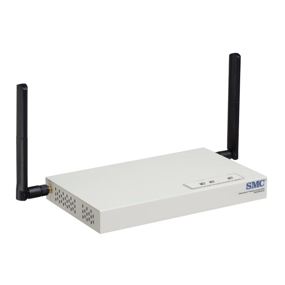
Hardware Description Rear Panel RJ-45 Port Security Slot 5 VDC Power Socket Console Reset Port Button Antennas The access point includes integrated diversity antennas for wireless communications. A diversity antenna system uses two identical antennas to receive and transmit signals, helping to avoid multipath fading effects. When receiving, the access point checks both antennas and selects the one with the strongest signal. -
Page 28: Security Slot
Introduction Status Description Indicates that the system is working normally. Flashing Indicates running a self-test or loading the software program. Flashing (Prolonged) Indicates system errors. Link Indicates a valid 10/100 Mbps Ethernet cable link. Flashing Indicates that the access point is transmitting or receiving data on a 10/100 Mbps Ethernet LAN. -
Page 29: Reset Button
Features and Benefits Reset Button This button is used to reset the access point or restore the factory default configuration. If you hold down the button for less than 5 seconds, the access point will perform a hardware reset. If you hold down the button for 5 seconds or more, any configuration changes you may have made are removed, and the factory default configuration is restored to the access point. -
Page 30: System Defaults
Introduction System Defaults The following table lists some of the access point’s basic system defaults. To reset the access point defaults, use the CLI command “reset configuration” from the Exec level prompt. Table 1-1. System Defaults Feature Parameter Default Identification System Name Administration User Name... - Page 31 System Defaults Table 1-1. System Defaults Feature Parameter Default MAC Authentication Disabled Authentication Session Timeout 0 minutes (disabled) Local MAC System Default Allowed Local MAC Permission Allowed 802.1X Authentication Status Disabled Broadcast Key Refresh 0 minutes (disabled) Session Key Refresh 0 minutes (disabled) Reauthentication Refresh Rate 0 seconds (disabled)
- Page 32 Introduction Table 1-1. System Defaults Feature Parameter Default System Logging Syslog Disabled Logging Host Disabled Logging Console Disabled IP Address / Host Name 0.0.0.0 Logging Level Informational Logging Facility Type System Clock SNTP Server Status Enabled SNTP Server 1 IP 137.92.140.80 SNTP Server 2 IP 192.43.244.18...
- Page 33 System Defaults Table 1-1. System Defaults Feature Parameter Default Antenna ID 0x0000 Wireless Interface 802.11b/g (contd.) Antenna Location Indoor Wireless Security Authentication Type Open System 802.11b/g Data Encryption Disabled WEP Key Length 128 bits WEP Key Type Hexadecimal WEP Transmit Key Number WEP Keys null WPA Configuration Mode...
- Page 34 Introduction 1-10...
-
Page 35: Chapter 2: Hardware Installation
Chapter 2: Hardware Installation Select a Site – Choose a proper place for the access point. In general, the best location is at the center of your wireless coverage area, within line of sight of all wireless devices. Try to place the access point in a position that can best cover its Basic Service Set (refer to “Infrastructure Wireless LAN”... - Page 36 Connect the Console Port – Connect the console cable (included) to the RS-232 console port for accessing the command-line interface. You can manage the access point using the console port (Chapter 6), the web interface (Chapter 5), or SNMP management software such as SMC’s EliteView.
-
Page 37: Chapter 3: Network Configuration
Chapter 3: Network Configuration Wireless networks support a stand-alone configuration as well as an integrated configuration with 10/100 Mbps Ethernet LANs. The 2.4 GHz Wireless Access Point also provides repeater and bridging services. Access points can be deployed to support wireless clients and connect wired LANs in the following configurations: •... -
Page 38: Network Topologies
Network Configuration Network Topologies Ad Hoc Wireless LAN (no Access Point) An ad hoc wireless LAN consists of a group of computers, each equipped with a wireless adapter, connected via radio signals as an independent wireless LAN. Computers in a specific ad hoc wireless LAN must therefore be configured to the same radio channel. -
Page 39: Infrastructure Wireless Lan
Network Topologies Infrastructure Wireless LAN The access point also provides access to a wired LAN for wireless workstations. An integrated wired/wireless LAN is called an Infrastructure configuration. A Basic Service Set (BSS) consists of a group of wireless PC users, and an access point that is directly connected to the wired LAN. -
Page 40: Infrastructure Wireless Lan For Roaming Wireless Pcs
Network Configuration Infrastructure Wireless LAN for Roaming Wireless PCs The Basic Service Set (BSS) defines the communications domain for each access point and its associated wireless clients. The BSS ID is a 48-bit binary number based on the access point’s wireless MAC address, and is set automatically and transparently as clients associate with the access point. -
Page 41: Infrastructure Wireless Bridge
Network Topologies Infrastructure Wireless Bridge The IEEE 802.11 standard defines a WIreless Distribution System (WDS) for bridge connections between BSS areas (access points). The access point uses WDS to forward traffic on links between units. The access point supports WDS bridge links on the 2.4 GHz (802.11b/g) band and can be used with various external antennas to offer flexible deployment options. -
Page 42: Infrastructure Wireless Repeater
Network Configuration Infrastructure Wireless Repeater The access point can also operate in a bridge “repeater” mode to extend the range of links to wireless clients. The access point uses WDS to forward traffic between the repeater bridge and the root bridge. The access point supports up to six WDS repeater links. -
Page 43: Chapter 4: Initial Configuration
Chapter 4: Initial Configuration The 2.4 GHz Wireless Access Point offers a variety of management options, including a web-based interface, a direct connection to the console port, Telnet, Secure Shell (SSH), or using SNMP software. The initial configuration steps can be made through the web browser interface or CLI. -
Page 44: Initial Configuration Steps
Initial Configuration For a description of how to use the CLI, see “Using the Command Line Interface” on page 6-1. For a list of all the CLI commands and detailed information on using the CLI, refer to “Command Groups” on page 6-6. Initial Configuration Steps Logging In –... -
Page 45: Logging In
Logging In Setting the Country Code – Units sold in the United States are configured by default to use only radio channels 1-11 in 802.11b or 802.11g mode as defined by FCC regulations. Units sold in other countries are configured by default without a country code (i.e., 99). - Page 46 Initial Configuration The home page displays the Main Menu.
-
Page 47: Chapter 5: System Configuration
Chapter 5: System Configuration Before continuing with advanced configuration, first complete the initial configuration steps described in Chapter 4 to set up an IP address for the access point. The access point can be managed by any computer using a web browser (Internet Explorer 5.0 or above, or Netscape 6.2 or above). -
Page 48: Advanced Configuration
System Configuration Advanced Configuration The Advanced Configuration pages include the following options. Table 5-2. Menu Menu Description Page System Configures basic administrative and client access Identification Specifies the host name TCP / IP Settings Configures the IP address, subnet mask, gateway, and domain name servers RADIUS Configures the RADIUS server for wireless client authentication... -
Page 49: System Identification
Advanced Configuration Table 5-2. Menu Menu Description Page Station Station Shows the wireless clients currently associated with the access 5-88 point Event Logs Shows log messages stored in memory 5-91 System Identification The system name for the access point can be left at its default setting. However, modifying this parameter can help you to more easily distinguish different devices in your network. - Page 50 System Configuration CLI Commands for System Identification – Enter the global configuration mode, and use the system name command to specify a new system name. Then return to the Exec mode, and use the show system command to display the changes to the system identification settings.
-
Page 51: Tcp / Ip Settings
Advanced Configuration TCP / IP Settings Configuring the access point with an IP address expands your ability to manage the access point. A number of access point features depend on IP addressing to operate. Note: You can use the web browser interface to access IP addressing only if the access point already has an IP address that is reachable through your network. - Page 52 System Configuration • Subnet Mask: The mask that identifies the host address bits used for routing to specific subnets. • Default Gateway: The default gateway is the IP address of the router for the access point, which is used if the requested destination address is not on the local subnet. If you have management stations, DNS, RADIUS, or other network servers located on another subnet, type the IP address of the default gateway router in the text field provided.
-
Page 53: Radius
Advanced Configuration RADIUS Remote Authentication Dial-in User Service (RADIUS) is an authentication protocol that uses software running on a central server to control access to RADIUS-aware devices on the network. An authentication server contains a database of user credentials for each user that requires access to the network. A primary RADIUS server must be specified for the access point to implement IEEE 802.1X network access control and Wi-Fi Protected Access (WPA) wireless security. - Page 54 System Configuration...
- Page 55 Advanced Configuration MAC Address Format – MAC addresses can be specified in one of four formats, using no delimeter, with a single dash delimeter, with multiple dash delimeters, and with multiple colon delimeters. VLAN ID Format – A VLAN ID (a number between 1 and 4094) can be assigned to each client after successful authentication using IEEE 802.1X and a central RADIUS server.
- Page 56 System Configuration CLI Commands for RADIUS – From the global configuration mode, use the radius-server address command to specify the address of the primary or secondary RADIUS servers. (The following example configures the settings for the primary RADIUS server.) Configure the other parameters for the RADIUS server. Then use the show show radius command from the Exec mode to display the current settings for the primary and secondary RADIUS servers.
-
Page 57: Ssh Settings
Advanced Configuration SSH Settings Telnet is a remote management tool that can be used to configure the access point from anywhere in the network. However, Telnet is not secure from hostile attacks. The Secure Shell (SSH) can act as a secure replacement for Telnet. The SSH protocol uses generated public keys to encrypt all data transfers passing between the access point and SSH-enabled management station clients and ensures that data traveling over the network arrives unaltered. -
Page 58: Authentication
System Configuration CLI Commands for SSH – To enable the SSH server, use the ip ssh-server enable command from the CLI Ethernet interface configuration mode. To set the SSH server UDP port, use the ip ssh-server port command. To view the current settings, use the show system command from the CLI Exec mode (not shown in the following example). - Page 59 Advanced Configuration • The access point can also operate in a 802.1X supplicant mode. This enables the access point itself to be authenticated with a RADIUS server using a configured MD5 user name and password. This prevents rogue access points from gaining access to the network.
- Page 60 System Configuration • Radius MAC: The MAC address of the associating station is sent to a configured RADIUS server for authentication. When using a RADIUS authentication server for MAC address authentication, the server must first be configured in the Radius window (see “RADIUS”...
- Page 61 Advanced Configuration CLI Commands for Local MAC Authentication – Use the mac-authentication server command from the global configuration mode to enable local MAC authentication. Use the mac-authentication session-timeout command to set the authentication interval. Set the default action for MAC addresses not in the local table using the address filter default command, then enter MAC addresses in the local table using the address filter entry command.
- Page 62 System Configuration CLI Commands for RADIUS MAC Authentication – Use the mac-authentication server command from the global configuration mode to enable remote MAC authentication. Set the timeout value for re-authentication using the mac- authentication session-timeout command. Be sure to also configure connection settings for the RADIUS server (not shown in the following example).
-
Page 63: Filter Control
Advanced Configuration Filter Control The access point can employ network traffic frame filtering to control access to network resources and increase security. You can prevent communications between wireless clients and prevent access point management from wireless clients. Also, you can block specific Ethernet traffic from being forwarded by the access point. Inter Client STAs Communication Filter –... - Page 64 System Configuration • MAC Address: Specifies a MAC address to filter, in the form xx-xx-xx-xx-xx-xx. • Permission: Adds or deletes a MAC address from the filtering table. Ethernet Type Filter – Controls checks on the Ethernet type of all incoming and outgoing Ethernet packets against the protocol filtering table.
-
Page 65: Vlan
Advanced Configuration VLAN The access point can employ VLAN tagging support to control access to network resources and increase security. VLANs separate traffic passing between the access point, associated clients, and the wired network. There can be a VLAN assigned to each associated client, a default VLAN for each VAP (Virtual Access Point) interface, and a management VLAN for the access point. - Page 66 System Configuration When setting up VLAN IDs for each user on the RADIUS server, be sure to use the RADIUS attributes and values as indicated in the following table. Number RADIUS Attribute Value Tunnel-Type VLAN (13) Tunnel-Medium-Type Tunnel-Private-Group-ID VLANID (1 to 4094 as hexadecimal or string) VLAN IDs on the RADIUS server can be entered as hexadecimal digits or a string (see “radius-server vlan-format”...
-
Page 67: Wds Settings
Advanced Configuration WDS Settings Each access point radio interface can be configured to operate in a bridge or repeater mode, which allows it to forward traffic directly to other access point units. To set up bridge links between access point units, you must configure the wireless Distribution System (WDS) forwarding table by specifying the wireless MAC address of all units to which you want to forward traffic. - Page 68 System Configuration Spanning Tree Protocol – STP uses a distributed algorithm to select a bridging device (STP-compliant switch, bridge or router) that serves as the root of the spanning tree network. It selects a root port on each bridging device (except for the root device) which incurs the lowest path cost when forwarding a packet from that device to the root device.
- Page 69 Advanced Configuration designated ports. After determining the lowest cost spanning tree, it enables all root ports and designated ports, and disables all other ports. Network packets are therefore only forwarded between root ports and designated ports, eliminating any possible network loops. Once a stable network topology has been established, all bridges listen for Hello BPDUs (Bridge Protocol Data Units) transmitted from the root bridge.
- Page 70 System Configuration • Link Path Cost – This parameter is used by the STP to determine the best path between devices. Therefore, lower values should be assigned to ports attached to faster media, and higher values assigned to ports with slower media. (Path cost takes precedence over port priority.) •...
- Page 71 Advanced Configuration Enterprise AP(if-wireless g)#bridge role bridge 6-96 Enterprise AP(if-wireless g)#bridge-link child 2 00-08-3e-84-bc-6d 6-98 Enterprise AP(if-wireless g)#bridge-link child 3 00-08-3e-85-13-f2 Enterprise AP(if-wireless g)#bridge-link child 4 00-08-3e-84-79-31 Enterprise AP(if-wireless g)#bridge-link parent 00-08-2d-69-3a-51 6-97 Enterprise AP(if-wireless g)#exit Enterprise AP#show bridge link wireless g 6-101 Interface Wireless G WDS Information ====================================...
- Page 72 System Configuration CLI Commands for STP Settings – If the role of a radio interface is set to Repeater, Bridge or Root Bridge, STP can be enabled on the access point to maintain a valid network topology. To globally enable STP, use the bridge stp enable command from the CLI configuration mode.
-
Page 73: Ap Management
Advanced Configuration AP Management The Web, Telnet, and SNMP management interfaces are enabled and open to all IP addresses by default. To provide more security for management access to the access point, specific interfaces can be disabled and management restricted to a single IP address or a limited range of IP addresses. -
Page 74: Administration
System Configuration CLI Commands for AP Management features. Enterprise AP(config)#apmgmtip multiple 192.168.1.50 255.255.255.0 6-20 Enterprise AP(config)#apmgmtui SNMP enable 6-21 Administration Changing the Password Management access to the web and CLI interface on the access point is controlled through a single user name and password. You can also gain additional access security by using control filters (see “Filter Control”... - Page 75 Advanced Configuration CLI Commands for the Administrator’s User Name and Password – Use the username and password commands from the CLI configuration mode. Enterprise AP(config)#username bob 6-15 Enterprise AP(config)#password admin 6-15 Enterprise AP# Upgrading Firmware You can upgrade new access point software from a local file on the management workstation, or from an FTP or TFTP server.
- Page 76 System Configuration Before upgrading new software, verify that the access point is connected to the network and has been configured with a compatible IP address and subnet mask. If you need to download from an FTP or TFTP server, take the following additional steps: •...
- Page 77 Advanced Configuration managing the access point from a wireless client, the VLAN ID for the wireless client must be configured on a RADIUS server. Current version – Version number of runtime code. Firmware Upgrade Local – Downloads an operation code image file from the web management station to the access point using HTTP.
- Page 78 System Configuration CLI Commands for Downloading Software from a TFTP Server – Use the copy tftp file command from the Exec mode and then specify the file type, name, and IP address of the TFTP server. When the download is complete, the dir command can be used to check that the new file is present in the access point file system.
-
Page 79: System Log
Advanced Configuration System Log The access point can be configured to send event and error messages to a System Log Server. The system clock can also be synchronized with a time server, so that all the messages sent to the Syslog server are stamped with the correct time and date. - Page 80 System Configuration Logging Level – Sets the minimum severity level for event logging. (Default: Informational) The system allows you to limit the messages that are logged by specifying a minimum severity level. The following table lists the error message levels from the most severe (Emergency) to least severe (Debug).
- Page 81 Advanced Configuration CLI Commands for System Logging – To enable logging on the access point, use the logging on command from the global configuration mode. The logging level command sets the minimum level of message to log. Use the logging console command to enable logging to the console.
- Page 82 System Configuration • Primary Server: The IP address of an SNTP or NTP time server that the access point attempts to poll for a time update. • Secondary Server: The IP address of a secondary SNTP or NTP time server. The access point first attempts to update the time from the primary server;...
-
Page 83: Snmp
SNMP CLI Commands for the System Clock – The following example shows how to manually set the system time when SNTP server support is disabled on the access point. Enterprise AP(config)#no sntp-server enable 6-33 Enterprise AP(config)#sntp-server date-time 6-34 Enter Year<1970-2100>: 2003 Enter Month<1-12>: 10 Enter Day<1-31>: 10 Enter Hour<0-23>: 18... -
Page 84: Configuring Snmp And Trap Message Parameters
System Configuration Configuring SNMP and Trap Message Parameters The access point SNMP agent must be enabled to function (for versions 1, 2c, and 3 clients). Management access using SNMP v1 and v2c also requires community strings to be configured for authentication. Trap notifications can be enabled and sent to up to four management stations. - Page 85 SNMP Community Name (Read/Write) – Defines the SNMP community access string that has read/write access. Authorized management stations are able to both retrieve and modify MIB objects. (Maximum length: 23 characters, case sensitive; Default: private) Trap Destination (1 to 4) – Enables recipients (up to four) of SNMP notifications. •...
- Page 86 System Configuration Trap Configuration – Allows selection of specific SNMP notifications to send. The following items are available: • sysSystemUp - The access point is up and running. • sysSystemDown - The access point is about to shutdown and reboot. •...
- Page 87 SNMP • dot11StationAuthenticateFail - A client station has tried and failed to authenticate to the network. • Enable All Traps - Click the button to enable all the available traps. • Disable All Traps - Click the button to disable all the available traps. CLI Commands for SNMP and Trap Configuration –...
- Page 88 System Configuration To view the current SNMP settings, use the show snmp command. Enterprise AP#show snmp 6-53 SNMP Information ============================================== Service State : Enable Community (ro) : ***** Community (rw) : ***** Location : WC-19 Contact : Paul EngineId :80:00:07:e5:80:00:00:2e:62:00:00:00:18 EngineBoots:1 Trap Destinations: 192.168.1.9, Community: *****, State: Enabled...
-
Page 89: Configuring Snmpv3 Users
SNMP Configuring SNMPv3 Users The access point allows up to 10 SNMP v3 users to be configured. Each user must be defined by a unique name, assigned to one of three pre-defined security groups, and configured with specific authentication and encryption settings. User –... - Page 90 System Configuration CLI Commands for Configuring SNMPv3 Users – Use the snmp-server engine-id command to define the SNMP v3 engine before assigning users to groups. Use the snmp-server user command to assign users to one of the three groups and set the appropriate authentication and encryption types to be used.
-
Page 91: Configuring Snmpv3 Trap Filters
SNMP Configuring SNMPv3 Trap Filters SNMP v3 users can be configured to receive notification messages from the access point. An SNMP Target ID is created that specifies the SNMP v3 user, IP address, and UDP port. A user-defined notification filter can be created so that specific notifications can be prevented from being sent to particular targets. - Page 92 System Configuration Note: Only the New Filter page allows the Filter ID to be configured. Filter ID – A user-defined name that identifies the filter. (Maximum length: 32 characters) Subtree OID – Specifies MIB subtree to be filtered. The MIB subtree must be defined in the form “.1.3.6.1”...
-
Page 93: Configuring Snmpv3 Targets
SNMP Configuring SNMPv3 Targets An SNMP v3 notification Target ID is specified by the SNMP v3 user, IP address, and UDP port. A user-defined filter can also be assigned to specific targets to limit the notifications received to specific MIB objects. (Note that the filter must first be configured. - Page 94 System Configuration Target ID – A user-defined name that identifies a receiver of notifications. The access point supports up to 10 target IDs. (Maximum length: 32 characters) IP Address – Specifies the IP address of the receiving management station. UDP Port – The UDP port that is used on the receiving management station for notification messages.
-
Page 95: Radio Interface
Radio Interface Enterprise AP(config)#snmp-server targets mytraps 192.168.1.33 chris 6-47 Enterprise AP(config)#snmp-server filter-assignment mytraps trapfilter 6-49 Enterprise AP(config)#exit Enterprise AP#show snmp target 6-51 Host ID : mytraps User : chris IP Address : 192.168.1.33 UDP Port : 162 ============================= Enterprise AP#show snmp filter-assignments 6-52 HostID FilterID... - Page 96 System Configuration Radio Channel – The radio channel that the access point uses to communicate with wireless clients. When multiple access points are deployed in the same area, set the channel on neighboring access points at least five channels apart to avoid interference with each other.
- Page 97 Radio Interface Maximum Station Data Rate – The maximum data rate at which the access point transmits unicast packets on the wireless interface. The maximum transmission distance is affected by the data rate. The lower the data rate, the longer the transmission distance. (Default: 54 Mbps) Maximum Associated Clients –...
- Page 98 System Configuration Super G – The Atheros proprietary Super G performance enhancements are supported by the access point. These enhancements include bursting, compression, fast frames and dynamic turbo. Maximum throughput ranges between 40 to 60 Mbps for connections to Atheros-compatible clients. (Default: Disabled) Radio Mode –...
- Page 99 Radio Interface Fragmentation Length – Configures the minimum packet size that can be fragmented when passing through the access point. Fragmentation of the PDUs (Package Data Unit) can increase the reliability of transmissions because it increases the probability of a successful transmission due to smaller frame size. If there is significant interference present, or collisions due to high network utilization, try setting the fragment size to send smaller fragments.
- Page 100 System Configuration CLI Commands for Radio Settings – From the global configuration mode, enter the interface wireless g command to access the 802.11g radio interface. From the 802.11g interface mode, you can access radio settings that apply to all VAP interfaces.
- Page 101 Radio Interface Configuring VAP Radio Settings To configure VAP radio settings, select the Radio Settings page. Default VLAN ID – The VLAN ID assigned to wireless clients associated to the VAP interface that are not assigned to a specific VLAN by RADIUS server configuration. (Default: 1) Closed System –...
- Page 102 System Configuration WPA2 PMKSA Life Time – WPA2 provides fast roaming for authenticated clients by retaining keys and other security settings in a cache for each VAP. In this way, when clients roam back into a VAP they had previously been using, re-authentication is not required.
- Page 103 Radio Interface Configuring Rogue AP Detection To configure Rouge AP detection, select the Radio Settings page, and scroll down to the “Rouge AP” section. Rogue AP – A “rogue AP” is either an access point that is not authorized to participate in the wireless network, or an access point that does not have the correct security configuration.
- Page 104 System Configuration Note: While the access point scans a channel for rogue APs, wireless clients will not be able to connect to the access point. Therefore, avoid frequent scanning or scans of a long duration unless there is a reason to believe that more intensive scanning is required to find a rogue AP.
- Page 105 Radio Interface The access point implements QoS using the Wi-Fi Multimedia (WMM) standard. Using WMM, the access point is able to prioritize traffic and optimize performance when multiple applications compete for wireless network bandwidth at the same time. WMM employs techniques that are a subset of the developing IEEE 802.11e QoS standard and it enables the access point to inter operate with both WMM- enabled clients and other devices that may lack any WMM functionality.
- Page 106 System Configuration After a collision detection, a backoff wait time is calculated. The total wait time is the sum of a minimum wait time (Arbitration Inter-Frame Space, or AIFS) determined from the AIFSN, and a random backoff time calculated from a value selected from zero to the CW.
- Page 107 Radio Interface 5-61...
- Page 108 System Configuration WMM – Sets the WMM operational mode on the access point. When enabled, the parameters for each AC queue will be employed on the access point and QoS capabilities are advertised to WMM-enabled clients. (Default: Support) • Disable: WMM is disabled. •...
- Page 109 Radio Interface CLI Commands for WMM – Enter interface wireless mode and type wmm required for clients that want to associate with the access point. The wmm-acknowledge-policy command is used to enable or disable a policy for each access category. The wmmparms command defines detailed WMM parameters. Enterprise AP(if-wireless g)#wmm required 6-130 Enterprise AP(if-wireless g)#wmm-acknowledge-policy 0 noack...
- Page 110 To view the current 802.11g radio settings for the VAP interface, use the show interface wireless g 0 command. Enterprise AP#show interface wireless g 0 6-107 Wireless Interface Information ============================================================= --------------------Identification--------------------------- Description : SMC 802.11g Access Point SSID : SMC_G 0 Turbo Mode : DISABLED Channel : 36 (AUTO) Status...
- Page 111 Radio Interface ----------------Quality of Service--------------------------- WMM Mode : SUPPORTED WMM Acknowledge Policy AC0(Best Effort) : Ack AC1(Background) : Acknowledge AC2(Video) : Acknowledge AC3(Voice) : Acknowledge WMM BSS Parameters AC0(Best Effort) : logCwMin: logCwMax: 10 AIFSN: Admission Control: No TXOP Limit: 0.000 ms AC1(Background) : logCwMin: logCwMax: 10...
-
Page 112: Security
System Configuration Security The access point is configured by default as an “open system,” which broadcasts a beacon signal including the configured SSID. Wireless clients with an SSID setting of “any” can read the SSID from the beacon and automatically set their SSID to allow immediate connection to the nearest access point. - Page 113 Radio Interface Table 5-2. Wireless Security Considerations Security Client Support Implementation Considerations Mechanism WPA over 802.1X Requires WPA-enabled system • Provides robust security in WPA-only mode Mode and network card driver (i.e., WPA clients only) (native support provided in • Offers support for legacy WEP clients, but with Windows XP) increased security risk (i.e., WEP authentication keys disabled)
- Page 114 System Configuration The access point can simultaneously support clients using various different security mechanisms. The configuration for these security combinations are outlined in the following table. Note that MAC address authentication can be configured independently to work with all security mechanisms and is indicated separately in the table.
- Page 115 Radio Interface Table 5-3. Security Combinations Client Security RADIUS Configuration Summary Combination Server Authentication Dynamic WEP and Interface Detail Settings: Local or Disabled Yes 802.1x WPA Authentication: WPA Encryption: Enable WPA Clients: Supported Cipher Suite: WEP 802.1x: Required Set 802.1x key refresh and reauthentication rates Static and dynamic Enter 1 to 4 WEP keys Local or Disabled Yes...
- Page 116 System Configuration a. The configuration summary does not include the set up for MAC authentication (see page 4-15) or RADIUS server (see page 2-9). b. The configuration of RADIUS MAC authentication together with 802.1x WPA or WPA Pre-shared Key is not supported. c.
- Page 117 Radio Interface Enable – Enables radio communications on the VAP interface. (Default: Disabled) Note: You must first enable VAP interface 0 before you can enable other VAP interfaces. SSID – The name of the basic service set provided by a VAP interface. Clients that want to connect to the network through the access point must set their SSID to the same as that of an access point VAP interface.
- Page 118 System Configuration • Alphanumeric: Enter keys as 5 alphanumeric characters for 64 bit keys, 13 alphanumeric characters for 128 bit keys, or 16 alphanumeric characters for 152 bit keys. Key Number – Selects the key number to use for encryption for each VAP interface. If the clients have all four keys configured to the same values, you can change the encryption key to any of the eight settings without having to update the client keys.
- Page 119 Radio Interface Note: To use 802.1X on wireless clients requires a network card driver and 802.1X client software that supports the EAP authentication type that you want to use. Windows 2000 SP3 or later and Windows XP provide 802.1X client support. Windows XP also provides native WPA support.
- Page 120 Enterprise AP(if-wireless g: VAP[0])#transmit-key 1 6-117 Enterprise AP(if-wireless g: VAP[0])#exit Enterprise AP#show interface wireless g 0 6-107 Wireless Interface Information =============================================================== ----------------Identification------------------------------- Description : SMC 802.11g Access Point SSID : SMC_G 0 Channel : 11 (AUTO) Status : DISABLED MAC Address : 00:12:cf:05:95:08 ----------------802.11 Parameters----------------...
- Page 121 Radio Interface ----------------Security-------------------------------------- Closed System : Disabled Multicast cipher : WEP Unicast cipher : TKIP and AES WPA clients : DISABLED WPA Key Mgmt Mode : PRE SHARED KEY WPA PSK Key Type : PASSPHRASE WPA PSK Key : EMPTY PMKSA Lifetime : 720 minutes Encryption...
- Page 122 System Configuration AC0(Best Effort) : logCwMin: logCwMax: AIFSN: Admission Control: No TXOP Limit: 0.000 ms AC1(Background) : logCwMin: logCwMax: 10 AIFSN: Admission Control: No TXOP Limit: 0.000 ms AC2(Video) : logCwMin: logCwMax: AIFSN: Admission Control: No AC3(Voice) : logCwMin: logCwMax: AIFSN: Admission Control: No TXOP Limit: 1.504 ms...
- Page 123 Radio Interface Wi-Fi Protected Access (WPA) WPA employs a combination of several technologies to provide an enhanced security solution for 802.11 wireless networks. The access point supports the following WPA components and features: IEEE 802.1X and the Extensible Authentication Protocol (EAP): WPA employs 802.1X as its basic framework for user authentication and dynamic key management.
- Page 124 System Configuration When access is opened to both WPA and WEP clients, no authentication is provided for the WEP clients through shared keys. To support authentication for WEP clients in this mixed mode configuration, you can use either MAC authentication or 802.1X authentication.
- Page 125 Radio Interface known to be already authenticated, so it proceeds directly to key exchange and association. To configure WPA, click Security under Radio G. Select one of the VAP interfaces by clicking More. Select one of the WPA options in the Authentication Setup table, and then configure the parameters displayed beneath the table.
- Page 126 System Configuration The WPA configuration parameters are described below: Encryption – You must enable data encryption in order to enable all types of encryption (WEP, TKIP, or AES) in the access point. Pre-Authentication – When using WPA2 over 802.1X, pre-authentication can be enabled, which allows clients to roam to a new access point and be quickly associated without performing full 802.1X authentication.
- Page 127 Radio Interface The configuration settings for WPA are summarized below: Table 5-4. WPA Configuration Settings WPA and WPA2 pre-shared key only WPA and WPA2 over 802.1X Encryption: Enabled Encryption: Enabled Authentication Setup: WPA-PSK, WPA2-PSK, or Authentication Setup: WPA, WPA2, WPA-WPA2-mixed WPA-WPA2-mixed WPA Cipher Mode: WEP/TKIP/AES-CCMP WPA Cipher Mode: WEP/TKIP/AES-CCMP...
- Page 128 System Configuration CLI Commands for WPA Over 802.1X Security – First set 802.1X to required using the 802.1X command and set the 802.1X key refresh rates. Then 802.11g interface configuration mode, use the vap command to access each VAP interface to configure other security settings.
- Page 129 Radio Interface Open the Security page, and click More for one of the VAP interfaces. You can enable 802.1X as optionally supported or as required to enhance the security of the wireless network. (Default: Disable) • Disable: The access point does not support 802.1X authentication for any wireless client.
- Page 130 System Configuration • 802.1X Reauthentication Refresh Rate: The time period after which a connected client must be re-authenticated. During the re-authentication process of verifying the client’s credentials on the RADIUS server, the client remains connected the network. Only if re-authentication fails is network access blocked. (Range: 0-65535 seconds;...
-
Page 131: Status Information
Status Information Status Information The Status page includes information on the following items: Menu Description Page AP Status Displays configuration settings for the basic system and the 5-85 wireless interface Station Status Shows the wireless clients currently associated with the access 5-88 point Event Logs... - Page 132 System Configuration AP System Configuration – The AP System Configuration table displays the basic system configuration settings: • System Up Time: Length of time the management agent has been up. • MAC Address: The physical layer address for this device. •...
- Page 133 Status Information CLI Commands for Displaying System Settings – To view the current access point system settings, use the show system command from the Exec mode. To view the current radio interface settings, use the show interface wireless g 0 command (see page 6-107).
-
Page 134: Station Status
System Configuration Station Status The Station Status window shows the wireless clients currently associated with the access point. The Station Configuration page displays basic connection information for all associated stations as described below. Note that this page is automatically refreshed every five seconds. •... - Page 135 Status Information shared-key approach uses Wired Equivalent Privacy (WEP) to verify client identity by distributing a shared key to stations before attempting authentication. • Associated: Shows if the station has been successfully associated with the access point. Once authentication is completed, stations can associate with the current access point, or reassociate with a new access point.
- Page 136 System Configuration CLI Commands for Displaying Station Status – To view status of clients currently associated with the access point, use the show station command from the Exec mode. Enterprise AP#show station 6-108 Station Table Information =========================================================== if-wireless G VAP [0] 802.11g Channel : Auto No 802.11g Channel Stations.
-
Page 137: Event Logs
Status Information Event Logs The Event Logs window shows the log messages generated by the access point and stored in memory. The Event Logs table displays the following information: • Log Time: The time the log message was generated. • Event Level: The logging level associated with this message. For a description of the various levels, see “logging level”... - Page 138 System Configuration CLI Commands for Displaying the Logging Status – From the global configuration mode, use the show logging command. Enterprise AP#show loggging 6-31 Logging Information ============================================ Syslog State : Enabled Logging Console State : Enabled Logging Level : Alert Logging Facility Type : 16 Servers...
-
Page 139: Chapter 6: Command Line Interface
Chapter 6: Command Line Interface Using the Command Line Interface Accessing the CLI When accessing the management interface for the over a direct connection to the console port, or via a Telnet connection, the access point can be managed by entering command keywords and parameters at the prompt. -
Page 140: Entering Commands
Command Line Interface To access the access point through a Telnet session, you must first set the IP address for the access point, and set the default gateway if you are managing the access point from a different IP subnet. For example: Enterprise AP#configure Enterprise AP(config)#interface ethernet Enterprise AP(if-ethernet)#ip address 10.1.0.1 255.255.255.0 10.1.0.254... -
Page 141: Minimum Abbreviation
Entering Commands Enterprise AP(config)#username smith Minimum Abbreviation The CLI will accept a minimum number of characters that uniquely identify a command. For example, the command “configure” can be entered as con. If an entry is ambiguous, the system will prompt for further input. Command Completion If you terminate input with a Tab key, the CLI will print the remaining characters of a partial keyword up to the point of ambiguity. -
Page 142: Partial Keyword Lookup
Command Line Interface Partial Keyword Lookup If you terminate a partial keyword with a question mark, alternatives that match the initial letters are provided. (Remember not to leave a space between the command and question mark.) For example “s?” shows all the keywords starting with “s.” Enterprise AP#show s? snmp sntp... -
Page 143: Exec Commands
Entering Commands Exec Commands When you open a new console session on an access point, the system enters Exec command mode. Only a limited number of the commands are available in this mode. You can access all other commands only from the configuration mode. To access Exec mode, open a new console session with the user name “admin.”... -
Page 144: Command Line Processing
Command Line Interface Command Line Processing Commands are not case sensitive. You can abbreviate commands and parameters as long as they contain enough letters to differentiate them from any other currently available commands or parameters. You can use the Tab key to complete partial commands, or enter a partial command followed by the “?”... -
Page 145: General Commands
General Commands Table 6-2. Command Groups Command Group Description Page SNMP Configures community access strings and trap managers 6-39 Flash/File Manages code image or access point configuration files 6-54 RADIUS Configures the RADIUS client used with 802.1X authentication 6-57 802.1X Authentication Configures 802.1X authentication 6-64 MAC Address Configures MAC address authentication... -
Page 146: Configure
Command Line Interface configure This command activates Global Configuration mode. You must enter this mode to modify most of the settings on the access point. You must also enter Global Configuration mode prior to enabling the context modes for Interface Configuration. See “Using the Command Line Interface”... -
Page 147: Ping
General Commands Example This example shows how to return to the Exec mode from the Interface Configuration mode, and then quit the CLI session: Enterprise AP(if-ethernet)#exit Enterprise AP#exit CLI session with the Access Point is now closed Username: ping This command sends ICMP echo request packets to another node on the network. Syntax ping <host_name | ip_address>... -
Page 148: Reset
Command Line Interface reset This command restarts the system or restores the factory default settings. Syntax reset <board | configuration> • board - Reboots the system. • configuration - Resets the configuration settings to the factory defaults, and then reboots the system. Default Setting None Command Mode... -
Page 149: Show Line
System Management Commands show line This command displays the console port’s configuration settings. Command Mode Exec Example The console port settings are fixed at the values shown below. Enterprise AP#show line Console Line Information ====================================================== databits parity : none speed : 9600 stop bits ======================================================... -
Page 150: Country
Command Line Interface Table 6-4. System Management Commands Command Function Mode Page Web Server ip http port Specifies the port to be used by the web browser interface 6-17 ip http server Allows the access point to be monitored or configured from a 6-18 browser ip https port... -
Page 151: Default Setting
System Management Commands Table 6-5. Country Codes Country Code Country Code Country Code Country Code Belgium Guatemala Mexico Taiwan Honduras Monaco Thailand Belize Hong Kong Morocco Trinidad & Tobago Bolivia Hungary Netherlands Tunisia Brazil Iceland New Zealand Turkey Brunei India Norway Ukraine Darussalam... -
Page 152: Prompt
Command Line Interface • The available Country Code settings can be displayed by using the country ? command. Example Enterprise AP#country tw Enterprise AP# prompt This command customizes the CLI prompt. Use the no form to restore the default prompt. Syntax prompt <string>... -
Page 153: Username
System Management Commands Command Mode Global Configuration Example Enterprise AP(config)#system name AP Enterprise AP(config)# username This command configures the user name for management access. Syntax username <name> name - The name of the user. (Length: 3-16 characters, case sensitive) Default Setting admin Command Mode Global Configuration... -
Page 154: Ip Ssh-Server Enable
Command Line Interface ip ssh-server enable This command enables the Secure Shell server. Use the no form to disable the server. Syntax ip ssh-server enable no ip ssh-server Default Setting Interface enabled Command Mode Interface Configuration (Ethernet) Command Usage • The access point supports Secure Shell version 2.0 only. •... -
Page 155: Ip Telnet-Server Enable
System Management Commands ip telnet-server enable This command enables the Telnet server. Use the no form to disable the server. Syntax ip telnet-server enable no ip telnet-server Default Setting Interface enabled Command Mode Interface Configuration (Ethernet) Example Enterprise AP(if-ethernet)#ip telnet-server enable Enterprise AP(if-ethernet)# ip http port This command specifies the TCP port number used by the web browser interface. -
Page 156: Ip Http Server
Command Line Interface ip http server This command allows this device to be monitored or configured from a browser. Use the no form to disable this function. Syntax ip http server no ip http server Default Setting Enabled Command Mode Global Configuration Example Enterprise AP(config)#ip http server... -
Page 157: Ip Https Server
System Management Commands Example Enterprise AP(config)#ip https port 1234 Enterprise AP(config)# ip https server Use this command to enable the secure hypertext transfer protocol (HTTPS) over the Secure Socket Layer (SSL), providing secure access (i.e., an encrypted connection) to the access point’s Web interface. Use the no form to disable this function. -
Page 158: Apmgmtip
Command Line Interface APmgmtIP This command specifies the client IP addresses that are allowed management access to the access point through various protocols. Caution: Secure Web (HTTPS) connections are not affected by the UI Management or IP Management settings. Syntax APmgmtIP <multiple IP_address subnet_mask | single IP_address | any>... -
Page 159: Apmgmtui
System Management Commands APmgmtUI This command enables and disables management access to the access point through SNMP, Telnet and web interfaces. Caution: Secure Web (HTTPS) connections are not affected by the UI Management or IP Management settings. Syntax APmgmtUI <[SNMP | Telnet | Web] enable | disable> •... -
Page 160: Show System
Command Line Interface show system This command displays basic system configuration settings. Default Setting None Command Mode Exec Example Enterprise AP#show system System Information System Information ============================================================== Serial Number System Up time : 0 days, 1 hours, 34 minutes, 38 seconds System Name : Enterprise Wireless AP System Location... -
Page 161: Show Version
Address Filtering : ALLOWED System Default : ALLOW addresses not found in filter table. Filter Table ----------------------------------------------------------- No Filter Entries. Bootfile Information =================================== Bootfile : smc-img.bin =================================== Protocol Filter Information =========================================================== Local Bridge :DISABLED AP Management :ENABLED Ethernet Type Filter :DISABLED... - Page 162 Command Line Interface Hardware Version Information =========================================== Hardware version R01A =========================================== Ethernet Interface Information ======================================== IP Address : 192.168.0.151 Subnet Mask : 255.255.255.0 Default Gateway : 192.168.0.1 Primary DNS : 210.200.211.225 Secondary DNS : 210.200.211.193 Speed-duplex : 100Base-TX Full Duplex Admin status : Up Operational status...
- Page 163 System Management Commands Logging Information ===================================================== Syslog State : Disabled Logging Console State : Disabled Logging Level : Informational Logging Facility Type : 16 Servers 1: 0.0.0.0 , UDP Port: 514, State: Disabled 2: 0.0.0.0 , UDP Port: 514, State: Disabled 3: 0.0.0.0 , UDP Port: 514, State: Disabled...
- Page 164 No 802.11g Channel Stations. System Information ============================================================== Serial Number System Up time : 0 days, 0 hours, 16 minutes, 51 seconds System Name : SMC System Location System Contact : Contact System Country Code : 99 - NO_COUNTRY_SET MAC Address...
-
Page 165: Show Hardware
System Logging Commands SSH Server : ENABLED SSH Server Port : 22 Telnet Server : ENABLED DHCP Relay : DISABLED ============================================================== Version Information ========================================= Version: v4.3.2.2 Date : Dec 20 2005, 18:38:12 ========================================= Enterprise AP# show hardware This command displays the hardware version of the system. Command Mode Exec Example... -
Page 166: Logging On
Command Line Interface logging on This command controls logging of error messages; i.e., sending debug or error messages to memory. The no form disables the logging process. Syntax [no] logging on Default Setting Disabled Command Mode Global Configuration Command Usage The logging process controls error messages saved to memory. -
Page 167: Logging Console
System Logging Commands Example Enterprise AP(config)#logging host 1 10.1.0.3 Enterprise AP(config)# logging console This command initiates logging of error messages to the console. Use the no form to disable logging to the console. Syntax logging console no logging console Default Setting Disabled Command Mode Global Configuration... -
Page 168: Logging Facility-Type
Command Line Interface Command Usage Messages sent include the selected level down to Emergency level. Level Argument Description Emergency System unusable Alert Immediate action needed Critical Critical conditions (e.g., memory allocation, or free memory error - resource exhausted) Error Error conditions (e.g., invalid input, default used) Warning Warning conditions (e.g., return false, unexpected return) Notice... -
Page 169: Logging Clear
System Logging Commands Command Usage The command specifies the facility type tag sent in syslog messages. (See RFC 3164.) This type has no effect on the kind of messages reported by the access point. However, it may be used by the syslog server to sort messages or to store messages in the corresponding database. -
Page 170: Show Event-Log
Command Line Interface show event-log This command displays log messages stored in the access point’s memory. Syntax show event-log Command Mode Exec Example Enterprise AP#show event-log Mar 09 11:57:55 Information: 802.11g:11g Radio Interface Enabled Mar 09 11:57:55 Information: 802.11g:Radio channel updated to 8 Mar 09 11:57:34 Information: 802.11g:11g Radio Interface Enabled Mar 09 11:57:18... -
Page 171: Sntp-Server Ip
System Clock Commands sntp-server ip This command sets the IP address of the servers to which SNTP time requests are issued. Use the this command with no arguments to clear all time servers from the current list. Syntax sntp-server ip <1 | 2> <ip> •... -
Page 172: Sntp-Server Date-Time
Command Line Interface Command Mode Global Configuration Command Usage The time acquired from time servers is used to record accurate dates and times for log events. Without SNTP, the access point only records the time starting from the factory default set at the last bootup (i.e., 00:14:00, January 1, 1970). -
Page 173: Sntp-Server Daylight-Saving
System Clock Commands sntp-server daylight-saving This command sets the start and end dates for daylight savings time. Use the no form to disable daylight savings time. Syntax sntp-server daylight-saving no sntp-server daylight-saving Default Setting Disabled Command Mode Global Configuration Command Usage The command sets the system clock back one hour during the specified period. -
Page 174: Show Sntp
Command Line Interface Command Usage This command sets the local time zone relative to the Coordinated Universal Time (UTC, formerly Greenwich Mean Time or GMT), based on the earth’s prime meridian, zero degrees longitude. To display a time corresponding to your local time, you must indicate the number of hours and minutes your time zone is east (before) or west (after) of UTC. -
Page 175: Dhcp Relay Commands
DHCP Relay Commands DHCP Relay Commands Dynamic Host Configuration Protocol (DHCP) can dynamically allocate an IP address and other configuration information to network clients that broadcast a request. To receive the broadcast request, the DHCP server would normally have to be on the same subnet as the client. -
Page 176: Dhcp-Relay
Command Line Interface dhcp-relay This command configures the primary and secondary DHCP server addresses. Syntax dhcp-relay <primary | secondary> <ip_address> • primary - The primary DHCP server. • secondary - The secondary DHCP server. • ip_address - IP address of the server. Default Setting Primary and secondary: 0.0.0.0 Command Mode... -
Page 177: Snmp Commands
SNMP Commands SNMP Commands Controls access to this access point from management stations using the Simple Network Management Protocol (SNMP), as well as the hosts that will receive trap messages. Table 6-9. SNMP Commands Command Function Mode Page snmp-server community Sets up the community access string to permit access 6-40 to SNMP commands... -
Page 178: Snmp-Server Community
Command Line Interface snmp-server community This command defines the community access string for the Simple Network Management Protocol. Use the no form to remove the specified community string. Syntax snmp-server community string [ro | rw] no snmp-server community string • string - Community string that acts like a password and permits access to the SNMP protocol. -
Page 179: Snmp-Server Location
SNMP Commands Command Mode Global Configuration Example Enterprise AP(config)#snmp-server contact Paul Enterprise AP(config)# Related Commands snmp-server location (6-41) snmp-server location This command sets the system location string. Use the no form to remove the location string. Syntax snmp-server location <text> no snmp-server location text - String that describes the system location. -
Page 180: Snmp-Server Host
Command Line Interface Command Mode Global Configuration Command Usage • This command enables both authentication failure notifications and link-up-down notifications. • The snmp-server host command specifies the host device that will receive SNMP notifications. Example Enterprise AP(config)#snmp-server enable server Enterprise AP(config)# Related Commands snmp-server host (6-42) snmp-server host... -
Page 181: Snmp-Server Trap
SNMP Commands Command Usage The snmp-server host command is used in conjunction with the snmp-server enable server command to enable SNMP notifications. Example Enterprise AP(config)#snmp-server host 1 10.1.19.23 batman Enterprise AP(config)# Related Commands snmp-server enable server (6-41) snmp-server trap This command enables the access point to send specific SNMP traps (i.e., notifications). - Page 182 Command Line Interface - dot1xAuthFail - A 802.1X client station has failed RADIUS authentication. - dot1xSuppAuthenticated - A supplicant station has been successfully authenticated by the RADIUS server - localMacAddrAuthSuccess - A client station has successfully authenticated its MAC address with the local database on the access point.
-
Page 183: Snmp-Server Engine-Id
SNMP Commands snmp-server engine-id This command is used for SNMP v3. It is used to uniquely identify the access point among all access points in the network. Use the no form to delete the engine ID. Syntax snmp-server engine-id <engine-id> no snmp-server engine-id engine-id - Enter engine-id in hexadecimal (5-32 characters). - Page 184 Command Line Interface • The SNMP engine ID is used to compute the authentication/privacy digests from the pass phrase. You should therefore configure the engine ID with the snmp-server engine-id command before using this configuration command. • The access point enables SNMP v3 users to be assigned to three pre-defined groups.
-
Page 185: Snmp-Server Targets
SNMP Commands Example Enterprise AP(config)#snmp-server user User Name<1-32> :chris Group Name<1-32> :RWPriv Authtype(md5,<cr>none):md5 Passphrase<8-32>:a good secret Privacy(des,<cr>none) :des Passphrase<8-32>:a very good secret Enterprise AP(config)# snmp-server targets This command configures SNMP v3 notification targets. Use the no form to delete an SNMP v3 target. Syntax snmp-server targets <target-id>... -
Page 186: Snmp-Server Filter
Command Line Interface snmp-server filter This command configures SNMP v3 notification filters. Use the no form to delete an SNMP v3 filter or remove a subtree from a filter. Syntax snmp-server filter <filter-id> <include | exclude> <subtree> [mask {mask}] no snmp-server filter <filter-id> [subtree] •... -
Page 187: Snmp-Server Filter-Assignments
SNMP Commands snmp-server filter-assignments This command assigns SNMP v3 notification filters to targets. Use the no form to remove an SNMP v3 filter assignment. Syntax snmp-server filter-assignments <target-id> <filter-id> no snmp-server filter-assignments <target-id> • target-id - A user-defined name that identifies a receiver of SNMP notifications. -
Page 188: Show Snmp Users
Command Line Interface Example Enterprise AP#show snmp groups GroupName SecurityModel :USM SecurityLevel :NoAuthNoPriv GroupName :RWAuth SecurityModel :USM SecurityLevel :AuthNoPriv GroupName :RWPriv SecurityModel :USM SecurityLevel :AuthPriv Enterprise AP# show snmp users This command displays the SNMP v3 users and settings. Syntax show snmp users Command Mode Exec... -
Page 189: Show Snmp Target
SNMP Commands Example Enterprise AP#show snmp group-assignments GroupName :RWPriv UserName :chris Enterprise AP# Enterprise AP# show snmp target This command displays the SNMP v3 notification target settings. Syntax show snmp target Command Mode Exec Example Enterprise AP#show snmp target Host ID : mytraps User : chris... -
Page 190: Show Snmp Filter-Assignments
Command Line Interface show snmp filter-assignments This command displays the SNMP v3 notification filter assignments. Syntax show snmp filter-assignments Command Mode Exec Example Enterprise AP#show snmp filter-assignments HostID FilterID mytraps trapfilter Enterprise AP# 6-52... -
Page 191: Show Snmp
SNMP Commands show snmp This command displays the SNMP configuration settings. Command Mode Exec Example Enterprise AP#show snmp SNMP Information ============================================== Service State : Disable Community (ro) : ******** Community (rw) : ******** Location : R&D 2 Contact : David EngineId :80:00:07:e5:80:00:00:27:04:00:00:00:08 EngineBoots:3... -
Page 192: Flash/File Commands
Command Line Interface Flash/File Commands These commands are used to manage the system code or configuration files. Table 6-10. Flash/File Commands Command Function Mode Page bootfile Specifies the file or image used to start up the system 6-54 copy Copies a code image or configuration between flash Exec 6-55 memory and a FTP/TFTP server... -
Page 193: Copy
Flash/File Commands copy This command copies a boot file, code image, or configuration file between the access point’s flash memory and a FTP/TFTP server. When you save the configuration settings to a file on a FTP/TFTP server, that file can later be downloaded to the access point to restore system operation. -
Page 194: Delete
Command Line Interface The following example shows how to download a configuration file: Enterprise AP#copy tftp file 1. Application image 2. Config file 3. Boot block image Select the type of download<1,2,3>: [1]:2 TFTP Source file name:syscfg TFTP Server IP:192.168.1.19 Enterprise AP# delete This command deletes a file or image. -
Page 195: Dir
Enterprise AP# show bootfile This command displays the name of the current operation code file that booted the system. Syntax show snmp filter-assignments Command Mode Exec Example Enterprise AP#show bootfile Bootfile Information =================================== Bootfile : smc-img.bin =================================== Enterprise AP# 6-57... -
Page 196: Radius Client
Command Line Interface RADIUS Client Remote Authentication Dial-in User Service (RADIUS) is a logon authentication protocol that uses software running on a central server to control access for RADIUS-aware devices to the network. An authentication server contains a database of credentials, such as users names and passwords, for each wireless client that requires access to the access point. -
Page 197: Radius-Server Port
RADIUS Client Command Mode Global Configuration Example Enterprise AP(config)#radius-server address 192.168.1.25 Enterprise AP(config)# radius-server port This command sets the RADIUS server network port. Syntax radius-server [secondary] port <port_number> • secondary - Secondary server. • port_number - RADIUS server UDP port used for authentication messages. (Range: 1024-65535) Default Setting 1812... -
Page 198: Radius-Server Retransmit
Command Line Interface radius-server retransmit This command sets the number of retries. Syntax radius-server [secondary] retransmit number_of_retries • secondary - Secondary server. • number_of_retries - Number of times the access point will try to authenticate logon access via the RADIUS server. (Range: 1 - 30) Default Setting Command Mode Global Configuration... -
Page 199: Radius-Server Port-Accounting
RADIUS Client radius-server port-accounting This command sets the RADIUS Accounting server network port. Syntax radius-server [secondary] port-accounting <port_number> • secondary - Secondary server. If secondary is not specified, then the access point assumes you are configuring the primary RADIUS server. •... -
Page 200: Radius-Server Radius-Mac-Format
Command Line Interface Example Enterprise AP(config)#radius-server timeout-interim 500 Enterprise AP(config)# radius-server radius-mac-format This command sets the format for specifying MAC addresses on the RADIUS server. Syntax radius-server radius-mac-format <multi-colon | multi-dash | no-delimiter | single-dash> • multi-colon - Enter MAC addresses in the form xx:xx:xx:xx:xx:xx. •... -
Page 201: Show Radius
RADIUS Client show radius This command displays the current settings for the RADIUS server. Default Setting None Command Mode Exec Example Enterprise AP#show radius Radius Server Information ======================================== Status : Disabled : 0.0.0.0 Port : 1812 : ***** Retransmit Timeout Accounting Port : 0 (Disabled) InterimUpdate... -
Page 202: 802.1X Authentication
Command Line Interface 802.1X Authentication The access point supports IEEE 802.1X access control for wireless clients. This control feature prevents unauthorized access to the network by requiring an 802.1X client application to submit user credentials for authentication. Client authentication is then verified by a RADIUS server using EAP (Extensible Authentication Protocol) before the access point grants client access to the network. -
Page 203: 802.1X Broadcast-Key-Refresh-Rate
802.1X Authentication Command Mode Global Configuration Command Usage • When 802.1X is disabled, the access point does not support 802.1X authentication for any station. After successful 802.11 association, each client is allowed to access the network. • When 802.1X is supported, the access point supports 802.1X authentication only for clients initiating the 802.1X authentication process (i.e., the access point does NOT initiate 802.1X authentication). -
Page 204: 802.1X Session-Key-Refresh-Rate
Command Line Interface command specifies the interval after which unicast session keys are changed. • Dynamic broadcast key rotation allows the access point to generate a random group key and periodically update all key-management capable wireless clients. Example Enterprise AP(config)#802.1X broadcast-key-refresh-rate 5 Enterprise AP(config)# 802.1x session-key-refresh-rate This command sets the interval at which unicast session keys are refreshed for... -
Page 205: 802.1X-Supplicant Enable
802.1X Authentication Command Mode Global Configuration Example Enterprise AP(config)#802.1x session-timeout 300 Enterprise AP(config)# 802.1x-supplicant enable This command enables the access point to operate as an 802.1X supplicant for authentication. Use the no form to disable 802.1X authentication of the access point. -
Page 206: Show Authentication
Command Line Interface Command Mode Global Configuration Command Usage The access point currently only supports EAP-MD5 CHAP for 802.1X supplicant authentication. Example Enterprise AP(config)#802.1x-supplicant user WA6102 dot1xpass Enterprise AP(config)# show authentication This command shows all 802.1X authentication settings, as well as the address filter table. -
Page 207: Mac Address Authentication
MAC Address Authentication MAC Address Authentication Use these commands to define MAC authentication on the access point. For local MAC authentication, first define the default filtering policy using the address filter default command. Then enter the MAC addresses to be filtered, indicating if they are allowed or denied. -
Page 208: Address Filter Entry
Command Line Interface Related Commands address filter entry (6-70) 802.1x-supplicant user (6-67) address filter entry This command enters a MAC address in the filter table. Syntax address filter entry <mac-address> <allowed | denied> • mac-address - Physical address of client. (Enter six pairs of hexadecimal digits separated by hyphens;... -
Page 209: Mac-Authentication Server
MAC Address Authentication Command Mode Global Configuration Example Enterprise AP(config)#address filter delete 00-70-50-cc-99-1b Enterprise AP(config)# Related Commands 802.1x-supplicant user (6-67) mac-authentication server This command sets address filtering to be performed with local or remote options. Use the no form to disable MAC address authentication. Syntax mac-authentication server [local | remote] •... -
Page 210: Filtering Commands
Command Line Interface Default 0 (disabled) Command Mode Global Configuration Example Enterprise AP(config)#mac-authentication session-timeout 1 Enterprise AP(config)# Filtering Commands The commands described in this section are used to filter communications between wireless clients, control access to the management interface from wireless clients, and filter traffic using specific Ethernet protocol types. -
Page 211: Filter Ap-Manage
Filtering Commands Global Configuration Command Usage This command can disable wireless-to-wireless communications between clients via the access point. However, it does not affect communications between wireless clients and the wired network. Example Enterprise AP(config)#filter local-bridge Enterprise AP(config)# filter ap-manage This command prevents wireless clients from accessing the management interface on the access point. -
Page 212: Filter Uplink
Command Line Interface filter uplink This command adds or deletes MAC addresses from the uplink filtering table. Syntax filter uplink <add | delete> MAC address MAC address - Specifies a MAC address in the form xx-xx-xx-xx-xx-xx. A maximum of eight addresses can be added to the filtering table. Default Disabled Command Mode... -
Page 213: Filter Ethernet-Type Protocol
Filtering Commands Example Enterprise AP(config)#filter ethernet-type enable Enterprise AP(config)# Related Commands filter ethernet-type protocol (6-75) filter ethernet-type protocol This command sets a filter for a specific Ethernet type. Use the no form to disable filtering for a specific Ethernet type. Syntax filter ethernet-type protocol <protocol>... -
Page 214: Show Filters
Command Line Interface show filters This command shows the filter options and protocol entries in the filter table. Command Mode Exec Example Enterprise AP#show filters Protocol Filter Information ========================================================= Local Bridge :ENABLED AP Management :ENABLED Ethernet Type Filter :ENABLED Enabled Protocol Filters --------------------------------------------------------- Protocol: ARP ISO: 0x0806... -
Page 215: Bridge Role (Wds)
WDS Bridge Commands bridge role (WDS) This command selects the bridge operation mode for the radio interface. Syntax bridge role <ap | repeater | bridge | root-bridge > • ap - Operates only as an access point for wireless clients. •... -
Page 216: Bridge-Link Child
Command Line Interface Default Setting None Command Mode Interface Configuration (Wireless) Command Usage Every bridge (except the root bridge) in the wireless bridge network must specify the MAC address of the parent bridge that is linked to the root bridge, or the root bridge itself. -
Page 217: Bridge Dynamic-Entry Age-Time
WDS Bridge Commands bridge dynamic-entry age-time This command sets the time for aging out dynamic entries in the WDS forwarding table. Syntax bridge dynamic-entry age-time <seconds> seconds - The time to age out an address entry. (Range: 10-10000 seconds). Default Setting 300 seconds Command Mode Global Configuration... -
Page 218: Show Bridge Filter-Entry
Command Line Interface show bridge filter-entry This command displays current entries in the WDS forwarding table. Command Mode Exec Example Enterprise AP#show bridge filter-entry max entry numbers =512 current entry nums =13 ***************************************************************************** *********************** Bridge MAC Addr Table ******************************* ***************************************************************************** Port |Fwd_type| VlanID|origin life|remain Life| Type... - Page 219 WDS Bridge Commands Example Enterprise AP#show bridge link wireless g Interface Wireless G WDS Information ==================================== AP Role: Bridge Parent: 00-12-34-56-78-9a Child: Child 2: 00-08-12-34-56-de Child 3: 00-00-00-00-00-00 Child 4: 00-00-00-00-00-00 Child 5: 00-00-00-00-00-00 Child 6: 00-00-00-00-00-00 STAs: No WDS Stations. Enterprise AP# Enterprise AP#show bridge link wireless g 2 Port-No...
-
Page 220: Spanning Tree Commands
Command Line Interface Spanning Tree Commands The commands described in this section are used to set the MAC address table aging time and spanning tree parameters for both the Ethernet and wireless interfaces. Table 6-15. Bridge Commands Command Function Mode Page bridge stp enable Enables the Spanning Tree feature... -
Page 221: Bridge Stp Forwarding-Delay
Spanning Tree Commands bridge stp forwarding-delay Use this command to configure the spanning tree bridge forward time globally for the wireless bridge. Use the no form to restore the default. Syntax bridge stp forwarding-delay <seconds> no bridge stp forwarding-delay seconds - Time in seconds. (Range: 4 - 30 seconds) The minimum value is the higher of 4 or [(max-age / 2) + 1]. -
Page 222: Bridge Stp Max-Age
Command Line Interface Example Enterprise AP(config)#bridge stp hello-time 5 Enterprise AP(config)# bridge stp max-age Use this command to configure the spanning tree bridge maximum age globally for the wireless bridge. Use the no form to restore the default. Syntax bridge stp max-age <seconds> no bridge stp max-age seconds - Time in seconds. -
Page 223: Bridge-Link Path-Cost
Spanning Tree Commands Command Mode Global Configuration Command Usage Bridge priority is used in selecting the root device, root port, and designated port. The device with the highest priority becomes the STP root device. However, if all devices have the same priority, the device with the lowest MAC address will then become the root device. -
Page 224: Show Bridge Stp
Command Line Interface Default Setting Command Mode Interface Configuration Command Usage • This command defines the priority for the use of a port in the Spanning Tree Protocol. If the path cost for all ports on a wireless bridge are the same, the port with the highest priority (that is, lowest value) will be configured as an active link in the spanning tree. -
Page 225: Ethernet Interface Commands
Ethernet Interface Commands Ethernet Interface Commands The commands described in this section configure connection parameters for the Ethernet port and wireless interface. Table 6-16. Ethernet Interface Commands Command Function Mode Page interface ethernet Enters Ethernet interface configuration mode 6-87 dns primary- server Specifies the primary name server IC-E 6-88... -
Page 226: Dns Server
Command Line Interface dns server This command specifies the address for the primary or secondary domain name server to be used for name-to-address resolution. Syntax dns primary-server <server-address> dns secondary-server <server-address> • primary-server - Primary server used for name resolution. •... -
Page 227: Ip Dhcp
Ethernet Interface Commands Command Mode Interface Configuration (Ethernet) Command Usage • DHCP is enabled by default. To manually configure a new IP address, you must first disable the DHCP client with the no ip dhcp command. • You must assign an IP address to this device to gain management access over the network or to connect the access point to existing IP subnets. -
Page 228: Speed-Duplex
Command Line Interface • When you use this command, the access point will begin broadcasting DHCP client requests. The current IP address (i.e., default or manually configured address) will continue to be effective until a DHCP reply is received. Requests will be broadcast periodically by this device in an effort to learn its IP address. -
Page 229: Shutdown
Ethernet Interface Commands shutdown This command disables the Ethernet interface. To restart a disabled interface, use the no form. Syntax shutdown no shutdown Default Setting Interface enabled Command Mode Interface Configuration (Ethernet) Command Usage This command allows you to disable the Ethernet port due to abnormal behavior (e.g., excessive collisions), and reenable it after the problem has been resolved. -
Page 230: Wireless Interface Commands
Command Line Interface Example Enterprise AP#show interface ethernet Ethernet Interface Information ======================================== IP Address : 192.168.2.2 Subnet Mask : 255.255.255.0 Default Gateway : 192.168.1.253 Primary DNS : 192.168.1.55 Secondary DNS : 10.1.0.55 Speed-duplex : 100Base-TX Half Duplex Admin status : Up Operational status : Up ========================================... - Page 231 Wireless Interface Commands Table 6-17. Wireless Interface Commands Command Function Mode Page beacon-interval Configures the rate at which beacon signals are IC-W 6-100 transmitted from the access point dtim-period Configures the rate at which stations in sleep mode IC-W 6-101 must wake up to receive broadcast/multicast transmissions fragmentation- length...
-
Page 232: Interface Wireless
Command Line Interface interface wireless This command enters wireless interface configuration mode. Syntax interface wireless <g> • g - 802.11g radio interface. Default Setting None Command Mode Global Configuration Example To specify the 802.11g interface, enter the following command: Enterprise AP(config)#interface wireless g Enterprise AP(if-wireless g)# This command provides access to the VAP (Virtual Access Point) interface configuration mode. -
Page 233: Speed
Wireless Interface Commands speed This command configures the maximum data rate at which the access point transmits unicast packets. Syntax speed <speed> speed - Maximum access speed allowed for wireless clients. (Options for 802.11b/g: 1, 2, 5.5, 6, 9, 11, 12, 18, 24, 36, 48, 54 Mbps) Default Setting 54 Mbps Command Mode... -
Page 234: Channel
Command Line Interface channel This command configures the radio channel through which the access point communicates with wireless clients. Syntax channel <channel | auto> • channel - Manually sets the radio channel used for communications with wireless clients. (Range for 802.11b/g: 1 to 11) •... -
Page 235: Radio-Mode
Wireless Interface Commands Default Setting full Command Mode Interface Configuration (Wireless) Command Usage • The “min” keyword indicates minimum power. • The longer the transmission distance, the higher the transmission power required. But to support the maximum number of users in an area, you must keep the power as low as possible. -
Page 236: Preamble
Command Line Interface Example Enterprise AP(if-wireless g)#radio-mode g Enterprise AP(if-wireless g)# preamble This command sets the length of the signal preamble that is used at the start of a 802.11b/g data transmission. Syntax preamble [long | short] • long - Sets the preamble to long (192 microseconds). •... -
Page 237: Antenna Id
Wireless Interface Commands Default Setting Diversity Command Mode Interface Configuration (Wireless) Command Usage The antenna ID must be selected in conjunction with the antenna control method to configure proper use of any of the antenna options. Example Enterprise AP(if-wireless g)#antenna control right Enterprise AP(if-wireless g)# antenna id This command specifies the antenna type connected to the access point... -
Page 238: Antenna Location
Command Line Interface antenna location This command selects the antenna mounting location for the radio interface. Syntax antenna location <indoor | outdoor> • indoor - The antenna is mounted indoors. • outdoor - The antenna is mounted outdoors. Default Setting Indoor Command Mode Interface Configuration (Wireless) -
Page 239: Dtim-Period
Wireless Interface Commands dtim-period This command configures the rate at which stations in sleep mode must wake up to receive broadcast/multicast transmissions. Syntax dtim-period <interval> interval - Interval between the beacon frames that transmit broadcast or multicast traffic. (Range: 1-255 beacon frames) Default Setting Command Mode Interface Configuration (Wireless) -
Page 240: Rts-Threshold
Command Line Interface Default Setting 2346 Command Mode Interface Configuration (Wireless) Command Usage • If the packet size is smaller than the preset Fragment size, the packet will not be segmented. • Fragmentation of the PDUs (Package Data Unit) can increase the reliability of transmissions because it increases the probability of a successful transmission due to smaller frame size. -
Page 241: Super-G
Wireless Interface Commands CTS frame to notify the sending station that it can start sending data. • Access points contending for the wireless medium may not be aware of each other. The RTS/CTS mechanism can solve this “Hidden Node” problem. Example Enterprise AP(if-wireless g)#rts-threshold 256 Enterprise AP(if-wireless g)#... -
Page 242: Ssid
Command Line Interface Example Enterprise AP(if-wireless g: VAP[0])#description RD-AP#3 Enterprise AP(if-wireless g: VAP[0])# ssid This command configures the service set identifier (SSID). Syntax ssid <string> string - The name of a basic service set supported by the access point. (Range: 1 - 32 characters) Default Setting 802.11g Radio: SMC_VAP_11G0 (0 to 7) Command Mode... -
Page 243: Max-Association
Wireless Interface Commands Example Enterprise AP(if-wireless g: VAP[0])#closed-system Enterprise AP(if-wireless g)# max-association This command configures the maximum number of clients that can be associated with the access point at the same time. Syntax max-association <count> count - Maximum number of associated stations. (Range: 0-64) Default Setting Command Mode Interface Configuration (Wireless-VAP) -
Page 244: Shutdown
Command Line Interface Syntax auth-timeout-value <minutes> minutes - The number of minutes before re-authentication. (Range: 5-60) Default Setting Command Mode Interface Configuration (Wireless-VAP) Example Enterprise AP(if-wireless g: VAP[0])#auth-timeout-value 40 Enterprise AP(if-wireless g: VAP[0])# shutdown This command disables the wireless interface. Use the no form to restart the interface. -
Page 245: Show Interface Wireless
Wireless Interface Commands show interface wireless This command displays the status for the wireless interface. Syntax show interface wireless <g> vap-id • g - 802.11g radio interface. • vap-id - The number that identifies the VAP interface. (Options: 0~7) Command Mode Exec Example Enterprise AP#show interface wireless g 0... -
Page 246: Show Station
Command Line Interface show station This command shows the wireless clients associated with the access point. Command Mode Exec Example Enterprise AP#show station Station Table Information ======================================================== if-wireless G VAP [1] 802.11g Channel : 1 No 802.11g Channel Stations. Enterprise AP# Rogue AP Detection Commands A “rogue AP”... -
Page 247: Rogue-Ap Enable
Rogue AP Detection Commands rogue-ap enable This command enables the periodic detection of nearby access points. Use the no form to disable periodic detection. Syntax [no] rogue-ap enable Default Setting Disabled Command Mode Interface Configuration (Wireless) Command Usage • While the access point scans a channel for rogue APs, wireless clients will not be able to connect to the access point. -
Page 248: Rogue-Ap Authenticate
Command Line Interface Example Enterprise AP(if-wireless g)#rogue-ap enable configure either syslog or trap or both to receive the rogue APs detected. Enterprise AP(if-wireless g)# rogue-ap authenticate This command forces the unit to authenticate all access points on the network. Use the no form to disable this function. -
Page 249: Rogue-Ap Interval
Rogue AP Detection Commands Default Setting 350 milliseconds Command Mode Interface Configuration (Wireless) Command Usage • During a scan, client access may be disrupted and new clients may not be able to associate to the access point. If clients experience severe disruption, reduce the scan duration time. -
Page 250: Rogue-Ap Scan
Command Line Interface rogue-ap scan This command starts an immediate scan for access points on the radio interface. Default Setting Disabled Command Mode Interface Configuration (Wireless) Command Usage While the access point scans a channel for rogue APs, wireless clients will not be able to connect to the access point. -
Page 251: Wireless Security Commands
Wireless Security Commands Wireless Security Commands The commands described in this section configure parameters for wireless security on the 802.11g interface. Table 6-19. Wireless Security Commands Command Function Mode Page auth Defines the 802.11 authentication type allowed by the IC-W-VAP 6-116 access point encryption... - Page 252 Command Line Interface • wpa2-psk - Clients using WPA2 with a Pre-shared Key are accepted for authentication. • wpa-wpa2-mixed - Clients using WPA or WPA2 are accepted for authentication. • wpa-wpa2-psk-mixed - Clients using WPA or WPA2 with a Pre-shared Key are accepted for authentication •...
-
Page 253: Encryption
Wireless Security Commands association request to the access point. For mixed-mode operation, the cipher used for broadcast frames is always TKIP. WEP encryption is not allowed. • The “required” option places the VAP into TKIP only mode. The “supported” option places the VAP into TKIP+AES+WEP mode. The “required” mode is used in WPA-only environments. -
Page 254: Key
Command Line Interface Example Enterprise AP(if-wireless g: VAP[0])#encryption Enterprise AP(if-wireless g)# Related Commands key (6-116) This command sets the keys used for WEP encryption. Use the no form to delete a configured key. Syntax key <index> <size> <type> <value> no key index •... -
Page 255: Transmit-Key
Wireless Security Commands • The encryption index, length and type configured in the access point must match those configured in the clients. Example Enterprise AP(if-wireless g)#key 1 64 hex 1234512345 Enterprise AP(if-wireless g)#key 2 128 ascii asdeipadjsipd Enterprise AP(if-wireless g)#key 3 64 hex 12345123451234512345123456 Enterprise AP(if-wireless g)# Related Commands key (6-116) -
Page 256: Cipher-Suite
Command Line Interface cipher-suite This command defines the cipher algorithm used to encrypt the global key for broadcast and multicast traffic when using Wi-Fi Protected Access (WPA) security. Syntax multicast-cipher <aes-ccmp | tkip | wep> • aes-ccmp - Use AES-CCMP encryption for the unicast and multicast cipher. -
Page 257: Mic_Mode
Wireless Security Commands • AES-CCMP (Advanced Encryption Standard Counter-Mode/CBCMAC Protocol): WPA2 is backward compatible with WPA, including the same 802.1X and PSK modes of operation and support for TKIP encryption. The main enhancement is its use of AES Counter-Mode encryption with Cipher Block Chaining Message Authentication Code (CBC-MAC) for message integrity. -
Page 258: Wpa-Pre-Shared-Key
Command Line Interface Example Enterprise AP(if-wireless g)#mic_mode hardware Enterprise AP(if-wireless g)# wpa-pre-shared-key This command defines a Wi-Fi Protected Access (WPA/WPA2) preshared-key. Syntax wpa-pre-shared-key <hex | passphrase-key> <value> • hex - Specifies hexadecimal digits as the key input format. • passphrase-key - Specifies an ASCII pass-phrase string as the key input format. -
Page 259: Pre-Authentication
Wireless Security Commands Command Mode Interface Configuration (Wireless-VAP) Command Usage • WPA2 provides fast roaming for authenticated clients by retaining keys and other security information in a cache, so that if a client roams away from an access point and then returns reauthentication is not required. •... -
Page 260: Link Integrity Commands
Command Line Interface known to be already authenticated, so it proceeds directly to key exchange and association. • To support pre-authentication, both clients and access points in the network must be WPA2 enabled. • Pre-authentication requires all access points in the network to be on the same IP subnet. -
Page 261: Link-Integrity Ping-Detect
Link Integrity Commands link-integrity ping-detect This command enables link integrity detection. Use the no form to disable link integrity detection. Syntax [no] link-integrity ping-detect Default Setting Disabled Command Mode Global Configuration Command Usage • When link integrity is enabled, the IP address of a host device in the wired network must be specified. -
Page 262: Link-Integrity Ping-Interval
Command Line Interface link-integrity ping-interval This command configures the time between each Ping sent to the link host. Syntax link-integrity ping-interval <interval> interval - The time between Pings. (Range: 5 - 60 seconds) Default Setting 30 seconds Command Mode Global Configuration Example Enterprise AP(config)#link-integrity ping-interval 20 Enterprise AP(config)#... -
Page 263: Show Link-Integrity
Link Integrity Commands Command Mode Global Configuration Example Enterprise AP(config)#link-integrity ethernet-detect Notification : Ethernet Link Detect SUCCESS - RADIO(S) ENABLED Enterprise AP(config)# show link-integrity This command displays the current link integrity configuration. Command Mode Exec Example Enterprise AP#show link-integrity Link Integrity Information =========================================================== Ethernet Detect : Enabled Ping Detect... -
Page 264: Iapp Commands
Command Line Interface IAPP Commands The command described in this section enables the protocol signaling required to ensure the successful handover of wireless clients roaming between different 802.11f-compliant access points. In other words, the 802.11f protocol can ensure successful roaming between access points in a multi-vendor environment. iapp This command enables the protocol signaling required to hand over wireless clients roaming between different 802.11f-compliant access points. -
Page 265: Vlan Commands
VLAN Commands VLAN Commands The access point can enable the support of VLAN-tagged traffic passing between wireless clients and the wired network. Up to 64 VLAN IDs can be mapped to specific wireless clients, allowing users to remain within the same VLAN as they move around a campus site. -
Page 266: Management-Vlanid
Command Line Interface • Traffic entering the Ethernet port must be tagged with a VLAN ID that matches the access point’s native VLAN ID, or with a VLAN tag that matches one of the wireless clients currently associated with the access point. -
Page 267: Wmm Commands
WMM Commands Default Setting Command Mode Interface Configuration (Wireless-VAP) Command Usage • To implement the default VLAN ID setting for VAP interface, the access point must enable VLAN support using the vlan command. • When VLANs are enabled, the access point tags frames received from wireless clients with the default VLAN ID for the VAP interface. -
Page 268: Wmm
Command Line Interface This command sets the WMM operational mode on the access point. Use the no form to disable WMM. Syntax [no] wmm <supported | required> • supported - WMM will be used for any associated device that supports this feature. -
Page 269: Wmmparam
WMM Commands interpretability with other wired network QoS policies. While the four ACs are specified for specific types of traffic, WMM allows the priority levels to be configured to match any network-wide QoS policy. WMM also specifies a protocol that access points can use to communicate the configured traffic priority levels to QoS-enabled wireless clients. - Page 270 Command Line Interface • admission_control - The admission control mode for the access category. When enabled, clients are blocked from using the access category. (Options: 0 to disable, 1 to enable) Default AP Parameters WMM Parameters AC0 (Best Effort) AC1 (Background) AC2 (Video) AC3 (Voice) LogCwMin LogCwMax...
-
Page 271: Appendix A: Troubleshooting
Appendix A: Troubleshooting Check the following items before you contact local Technical Support. If wireless clients cannot access the network, check the following: • Be sure the access point and the wireless clients are configured with the same Service Set ID (SSID). •... - Page 272 Troubleshooting If you cannot access the on-board configuration program via a serial port connection: • Be sure you have set the terminal emulator program to VT100 compatible, 8 data bits, 1 stop bit, no parity and 9600 bps. • Check that the null-modem serial cable conforms to the pin-out connections provided on page B-3.
-
Page 273: Appendix B: Cables And Pinouts
Appendix B: Cables and Pinouts Twisted-Pair Cable Assignments For 10/100BASE-TX connections, a twisted-pair cable must have two pairs of wires. Each wire pair is identified by two different colors. For example, one wire might be green and the other, green with white stripes. Also, an RJ-45 connector must be attached to both ends of the cable. -
Page 274: Straight-Through Wiring
Cables and Pinouts Table B-1. 10/100BASE-TX MDI Port Pinouts MDI Signal Name Transmit Data plus (TD+) Transmit Data minus (TD-) Receive Data plus (RD+) GND (Positive Vport) GND (Positive Vport) Receive Data minus (RD-) -48V feeding power (Negative- Vport) -48V feeding power (Negative- Vport) Note: The “+”... -
Page 275: Crossover Wiring
Console Port Pin Assignments Crossover Wiring Because the 10/100 Mbps port on the access point uses an MDI pin configuration, you must use “crossover” cable for network connections to PCs, servers or other end nodes that only have MDI ports. However, if the device to which you are connecting supports auto-MDIX operation, you can use either “straight-through”... -
Page 276: Wiring Map For Serial Cable
Cables and Pinouts Wiring Map for Serial Cable Table B-2. Wiring Map for Serial Cable DB9 Male (AP Console) DB9 Male (PC DTE) Function Function Unused Unused RXD (receive data) TXD (transmit data) TXD (transmit data) RXD (receive data) Unused Unused GND (ground) GND (ground) -
Page 277: Appendix C: Specifications
Appendix C: Specifications General Specifications Maximum Channels 802.11b/g: FCC/IC: 1-11 ETSI: 1-13 France: 10-13 MKK: 1-14 Taiwan: 1-11 Maximum Clients 64 per VAP interface Operating Range See “Operating Range” on page C-5 Data Rate 802.11g: 6, 9, 11, 12, 18, 24, 36, 48, 54 Mbps per channel 802.11b: 1, 2, 5.5, 11 Mbps per channel Modulation Type 802.11g: CCK, BPSK, QPSK, OFDM... - Page 278 Specifications PoE (DC) Input voltage: 48 volts, 0.2 A, 12.96 watts Note: Power can also be provided to the access point through the Ethernet port based on IEEE 802.3af Power over Ethernet (PoE) specifications. When both PoE is provided and the adapter is plugged in, PoE will be turned off. Physical Size 21 x 12.5 x 2.6cm (8.27 x 4.92x 1.02 in) Weight...
-
Page 279: Sensitivity
Sensitivity Sensitivity IEEE 802.11g Data Rate Sensitivity (dBm) 6 Mbps 9 Mbps 12 Mbps 17 Mbps 24 Mbps 36 Mbps 48 Mbps 54 Mbps IEEE 802.11b Data Rate Sensitivity (dBm) 1 Mbps 2 Mbps 5.5 Mbps 11 Mbps Transmit Power IEEE 802.11g Maximum Output Power (GHz - dBm) Data Rate... - Page 280 Specifications IEEE 802.11g Maximum Output Power (GHz - dBm) Data Rate 2.412 2.417~2.467 2.472 54 Mbps 108 Mbps IEEE 802.11b Maximum Output Power (GHz - dBm) Data Rate 2.412 2.417~2.467 2.472 1 Mbps 2 Mbps 5.5 Mbps 11 Mbps...
-
Page 281: Operating Range
Transmit Power Operating Range Important Notice Maximum distances posted below are actual tested distance thresholds. However, there are many variables such as barrier composition and construction and local environmental interference that may impact your actual distances and cause you to experience distance thresholds far lower than those posted below. - Page 282 Specifications...
-
Page 283: Glossary
Glossary 10BASE-T IEEE 802.3 specification for 10 Mbps Ethernet over two pairs of Category 3 or better UTP cable. 100BASE-TX IEEE 802.3u specification for 100 Mbps Fast Ethernet over two pairs of Category 5 or better UTP cable. Access Point An internetworking device that seamlessly connects wired and wireless networks. - Page 284 Glossary Broadcast Key Broadcast keys are sent to stations using 802.1X dynamic keying. Dynamic broadcast key rotation is often used to allow the access point to generate a random group key and periodically update all key-management capable wireless clients. CSMA/CA Carrier Sense Multiple Access with Collision Avoidance.
- Page 285 Glossary IEEE 802.11g A wireless standard that supports wireless communications in the 2.4 GHz band using using Orthogonal Frequency Division Multiplexing (OFDM). The standard provides for data rates of 6, 9, 11, 12, 18, 24, 36, 48, 54 Mbps. IEEE 802.11g is also backward compatible with IEEE 802.11b.
- Page 286 Glossary RADIUS A logon authentication protocol that uses software running on a central server to control access to the network. Roaming A wireless LAN mobile user moves around an ESS and maintains a continuous connection to the infrastructure network. RTS Threshold Transmitters contending for the medium may not be aware of each other.
- Page 287 Glossary Virtual Access Point (VAP) Virtual AP technology multiplies the number of Access Points present within the RF footprint of a single physical access device. With Virtual AP technology, WLAN users within the device’s footprint can associate with what appears to be different access points and their associated network services.
- Page 288 Glossary Glossary-6...
-
Page 289: Index
Index Numerics console port 1-4 connecting 2-2 802.11g 6-94 pin assignments B-3 required settings 4-1 country code AES 5-78 configuring 4-3, 6-12 antennas, positioning 2-2 crossover cable B-3 authentication 5-12, 6-113 CSMA/CA 1-1 cipher suite 5-80, 6-114 CTS 5-53, 6-102 closed system 6-104 configuring 5-12, 6-113 MAC address 5-13, 6-69, 6-70... - Page 290 Index filter 5-17, 6-69 address 5-12, 6-69 LED indicators 1-3 between wireless clients 5-17, 6-72 lock, Kensington 2-1 local bridge 5-17, 6-72 local or remote 5-12, 6-71 messages 5-34, 5-91, 6-28 management access 5-17, 6-73 server 5-33, 6-28 protocol types 6-74 login VLANs 5-55, 6-127 CLI 6-1...
- Page 291 Index Power over Ethernet See PoE specifications C-1 power supply, specifications C-1 PSK 5-77 server Status 5-11 SSID 5-71, 6-104 SSL 6-19 radio channel 802.11a interface 6-96 interface settings 6-85–?? 802.11g interface 5-50, 6-96 path cost 6-85 RADIUS 5-7, 5-77, 6-58 port priority 6-85 RADIUS, logon authentication 5-14, startup files, setting 6-54...
- Page 292 Index Wi-Fi Protected Access See WPA Wired Equivalent Protection See WEP WEP 5-71 WPA 5-77 configuring 5-71 pre-shared key 5-80, 6-120 shared key 5-72, 6-116 WPA, pre-shared key See PSK Wi-Fi Multimedia See WMM Index-4...
- Page 294 Informações sobre Suporte Técnico em www.smc.com SWEDISH Information om Teknisk Support finns tillgängligt på www.smc.com INTERNET E-mail address: techsupport@smc.com Driver updates http://www.smc.com/ index.cfm?action=tech_support_drivers_downloads World Wide Web http://www.smc.com/ SMC2552W-G2 149100034100E R03 20 Mason • Irvine, CA 92618 • Phn: 949-679-8000 • www.smc.com...