Sign In
Upload
Manuals
Brands
Tait Manuals
Radio
TM9100
Tait TM9100 Manuals
Manuals and User Guides for Tait TM9100. We have
10
Tait TM9100 manuals available for free PDF download: Service Manual, User Manual, Tune Up And Inspection, Installation Manual, Safety Information Manual
Tait TM9100 Service Manual (485 pages)
Brand:
Tait
| Category:
Radio
| Size: 26 MB
Table of Contents
Table of Contents
3
Scope of Manual
5
Preface
5
Hardware and Software Versions
5
Enquiries and Comments
5
Updates of Manual and Equipment
5
Copyright
6
Disclaimer
6
Associated Documentation
6
Issue
6
Abbreviations
7
Publication Record
7
Alert Notices
7
Chapter 1 Description of the Radio
11
Product Overview
13
Introduction
13
Frequency Bands
14
RF Output Power
14
Accessories Overview
15
Product Codes
16
Radio Bodies
16
Control Head
16
Labels
17
Compliance Information
17
Specifications
18
Typical Current Consumptions by Radio While Not Transmitting
21
Typical Current Consumptions by Radio Body While Transmitting
21
Description
23
Mechanical Design
23
Radio Body
24
Components of the Radio Body
25
Components of the Main-Board Assembly
27
Main Board
28
Heat-Transfer Block
28
Control Head Description
29
Front Panel Assembly
29
Keypads
29
LCD Assembly
29
Speaker
30
Concealed Microphone
30
Space-Frame
30
Seals
30
Components of the Control Head
31
Control-Head Board
32
Control-Head Loom
32
Adapter Flange
32
User Interface
33
Connectors
34
Connectors of the Radio Body (25W Radio)
35
RF Connector
36
Connectors of the Control Head
36
Power Connector
37
Auxiliary Connector
38
Internal Options Connector
39
Provision for External Options Connector
39
Control-Head Connectors
40
Microphone Connector
41
Hardware and Software Architecture
42
Hardware Architecture of the Main Board
43
Software Architecture
44
Software Modules
44
Software Start-Up
45
Software Shutdown
46
Programming and Calibration Files
46
Software Upgrades
46
Operation in Receive Mode
47
Transceiver Operation in Analog Mode
48
Transceiver Operation in Digital Mode
49
RF Hardware
50
Quadrature Demodulator
50
Automatic Gain Control
50
Noise Blanking
50
Digital Baseband Processing
51
Custom Logic
51
Noise Squelch
51
Rssi/Calibration
51
Audio Processing and Signaling
52
Data and Signaling Decoders (Analog Mode)
52
Side Tones
52
Rx Burst Builder (Digital Mode)
52
Rx Vocoder (Digital Mode)
53
Arbitration (Digital Mode)
53
Codec
53
Output to Speakers/Volume Control Configurations
53
Operation in Transmit Mode
54
Microphone Input
55
Analog Processing of the Microphone Input
55
Automatic Level Control
55
Tx Vocoder (Digital Mode)
55
Tx Vocoder FEC (Digital Mode)
56
Tx Burst Builder (Digital Mode)
56
Arbitrator (Digital Mode)
56
C4FM Modulator (Digital Mode)
56
Frequency Synthesizer
57
Frequency Control Loop
57
Rf Pll
57
Operation of Control Loop
57
Modulation
58
Frequency Generation
58
Fast Frequency Settling
58
RF Transmitter
59
Frequency Acquisition of RF PLL
59
Frequency Acquisition of FCL
59
Calibration
59
Power Control
60
Ramping
60
Bias Ramp-Up
60
Power Ramp-U
60
PIN Switch
61
Circuit Descriptions
63
Main Board Hardware Architecture
64
Transmitter Circuitry
65
Exciter
65
Power Amplifier
65
Power Control Loop
65
Block Diagram of the Transmitter Circuitry
66
Directional Coupler
67
Temperature Sensor
67
Receiver Circuitry
68
Front-End Circuitry
68
First Mixer
68
Frequencies of if Stages
68
Circuit Descriptions
68
Block Diagram of the Receiver Circuitry
69
Demodulation
70
Channel Filtering
70
Received Signal Strength Indication
70
Front-End AGC Control
70
Frequency Synthesizer Circuitry
71
Power Supplies
71
Performance Requirements
71
Effect of Tuning Range
71
Block Diagram of the Frequency Synthesizer Circuitry
72
Reference Frequency
73
Dual Vcos
73
Phase-Locked Loop
73
Active Loop Filter
73
Speed-Up Techniques
74
Frequency Control Loop Description
75
Elements of FCL Circuitry
75
Circuit Operation
75
FCL Modulation
75
CODEC and Audio Circuitry
76
Block Diagram of the CODEC and Audio Circuitry
77
Summing Circuit
78
Buffer Amplifier
78
Audio Power Amplifier
78
Microphone Signals
78
Auxiliary Audio Outputs
79
Power Supply Circuitry
80
Supply Protection
80
Supervisory Circuit
80
Internal Power Supplies
80
Block Diagram of the Power Supply Circuitry
81
Power-Sense Options
82
Block Diagram of Hardware Links LK1 to LK4
82
Configuration of Hardware Links and GPI Lines for Power-Sense Options
83
Battery Power Sense
84
Auxiliary Power Sense
84
Internal-Options Power Sense
84
No Power Sense
84
Operation in Emergency Mode
85
Connector Power Supply Options
85
Interface Circuitry
86
Bi-Directional Lines
86
Output Signals
86
5-Volt Regulator
86
Block Diagram of the Interface Circuitry
87
Digital Board
88
Input Signals
88
ESD Protection
88
Hookswitch Detection
88
Block Diagram of the Digital Board
89
Control-Head Board Description
90
Block Diagram of the Control-Head Board
91
Volume Control
92
Main Keypad
92
LCD Module
92
Keypad Backlighting
92
Chapter 2 Servicing the Radio
93
Repair Levels and Website Access
97
General Information
97
Tools, Equipment and Spares
100
Torque-Drivers
100
Tools for SMT Repairs
100
Test Equipment
100
Service Kit
101
Servicing Precautions
102
Use of Torque-Drivers
102
Non-Scratch Bench Tops
102
Sealing of Radio
102
General Information
102
ESD Precautions
103
Storage and Transport of Items
103
Anti-Static Workbenches
103
Transmitter Issues
104
Test Equipment Setup
105
Connect Equipment
105
Settings for Receive Tests
105
Settings for Transmit Tests
105
Test Setup
106
Replacing Board Components
107
Identify PCB Information
107
Identify Replacement Component
107
Obtain Replacement Component
107
Shielding Cans and Connectors
108
Shielding Cans and Connectors (Bottom Side of Main-Board Assembly)
109
SMT Repair Techniques
110
Spare Cans
110
Locations of Capacitors C548 and C565 and Inductors L601 and L602
111
Computer-Controlled Test Mode (CCTM)
112
Terminal Program for CCTM
112
Invoking CCTM
112
CCTM Commands in the Audio Category
113
CCTM Commands in Radio-Information, Radio-Control, System Categories
114
CCTM Commands in the Frequency-Synthesizer and Receiver Categories
115
CCTM Commands in the Transmitter Category
116
CCTM Commands for the Control-Head
118
CCTM Commands of the Remote Control-Head Kit
119
CCTM Error Codes
120
Visual and Audible Indications
121
Disassembly and Reassembly
123
Removing and Mounting the Control Head
124
Disassembling the Radio Body
125
Removing the Cover
125
Opening the Radio Body
126
Removing the Main-Board Assembly
126
Disassembling the Main-Board Assembly
128
Disassembly and Reassembly
128
Removing an Options Board
130
Reassembling the Radio Body
131
Reassembling the Main-Board Assembly
131
Contact Surfaces on the Bottom Side of the Main Board
131
Fitting the Main-Board Assembly to the Chassis
133
Closing the Radio Body
134
PAD TOP Can on the Top Side of the Main Board
134
Disassembling and Reassembling the Control Head
135
Speaker Orientation and Connectors of the Control-Head Board
135
Components of the Control Head View
137
Servicing Procedures
139
Initial Tasks
139
Initial Administration
139
Visual Inspection
139
Replace Damaged or Missing Knob
140
Check for Additional Damage
140
Replace Damaged Cover Assembly
140
Repair Damaged Control Head
140
Power up the Radio
141
Read the Programming File
142
Obtain the Details of the Software Feature Enabler
143
Read the Calibration File
143
Check the User Interface
143
Error Messages
144
Servicing Procedures
144
Check the Transmit and Transmit-Audio Functions
145
Check the Receive and Receive-Audio Functions
146
Final Tasks
147
Repair
147
Enable Software Features (SFE)
148
Final Inspection
149
Final Test
149
Final Administration
149
Final Tests of Transmitter Function
150
Final Tests of General Radio Functions
151
Power Supply Fault Finding
153
Three Types of Fault
153
Check Inputs to SMPS
154
Important Components of the Power-Supply Circuitry
155
Check 3.3 V Supply
156
Power-Supply Circuitry under the CDC BOT Can
158
Check Linear Regulators
158
Power Supply Fault Finding
158
Check Power-Up Configuration
159
Implementation of the Power-Up Options
159
Check Power-Up Options
160
Check Provision of External Power
162
Interface Fault Finding
163
Internal and Connector Signals
163
Types of Signals
163
Components of the Interface Circuitry
164
Check Output Lines
165
Components of the Interface Circuitry (Bottom Side)
166
Check Input Lines
167
Interface Fault Finding
168
Frequency Synthesizer Fault Finding
169
CCTM Commands for Diagnosis of Faults in Frequency Synthesizer
169
Initial Checks
170
Symptoms of Fault
170
Transmit and Receive Faults
170
System Error
171
Lock Status
172
Power Supplies Description
173
Measurement Points for Frequency Synthesizer Power Supply Circuitry
173
14V Power Supply
174
Frequency Synthesizer Fault Finding
174
Synthesizer Circuitry under Syn Top Can and 6 V Regulator IC606
175
Synthesizer Circuitry under the FCL Top Can
176
6V Power Supply
177
Synthesizer Circuitry under the Syn Bot and VCO Bot Cans
178
5V Power Supply
179
3V Power Supply
180
Phase-Locked Loop Description
181
Supply for Charge Pump
181
Test and Measurement Points for the Synthesizer PLL and Loop Filter
182
Components between the Digital Board and the Frequency Synthesizer
183
DIG SYN en Line
184
SYN LOCK Line
185
Synthesizer Circuitry under the SYN TOP Can
186
Loop Filter
187
Check Loop Voltage
187
VCO Faulty
188
Check Reference Voltage
188
Check Feedback Voltage
189
Check DIG SYN Fast Line
190
Check TP503 Test Point
191
Receive VCO and Related Circuitry (UHF Radios)
192
Measurement Points for the VCO and Related Circuitry in UHF Radios
193
Check Receive VCO
194
Synthesizer Circuitry under the SYN Top and VCO TOP Cans
195
Repair PLL Feedback
196
Synthesizer Circuitry under the VCO BOT Can
196
Repair Receive VCO
197
Check Switching to Receive Mode
198
Repair Switching Network
199
Check Receive Buffer Amplifier
200
Transmit VCO and Related Circuitry (UHF Radios)
201
Check Transmit VCO
202
Repair Transmit VCO
203
Check Switching to Transmit Mode
204
Check Transmit Buffer Amplifier
205
VCO and Related Circuitry (VHF Radios)
206
Minimum and Maximum Frequencies for the Different VHF Frequency Bands
206
Measurement Points for the VCO and Related Circuitry in VHF Radios
207
Check VCO
208
Repair VCO
211
Check Transmit-Receive Switch
212
Check Buffer Amplifier
214
Power Supply for FCL
215
Fault-Diagnosis Stages
215
Test and Measurement Points the FCL Circuitry
216
Power Supply
217
TCXO Circuitry under the CDC TOP Can
217
VCXO and TCXO Outputs
218
FCL Circuitry under and Adjacent the FCL TOP Can
219
FCL Circuitry under the VCXO BOT Can
220
Signals at TP501 and TP502
221
TP502 Test Point
221
TP501 Test Point
222
TP502 Test Point (TP501 Grounded)
223
VCXO and CODEC Circuitry
224
CCTM Checks
224
VCXO Tank Circuit
225
CODEC 2 Circuitry
226
Receiver Fault Finding
227
Fault Conditions
227
CCTM Commands Required for the Diagnosis of Faults in the Receiver
227
Faulty Receiver Sensitivity
228
Determine Extent of Sensitivity Loss
228
Receiver Circuitry under the if TOP Can
229
Excessive Loss of Sensitivity
230
Check Power Supplies
230
Receiver Circuitry under the LO2 BOT Can
231
Receiver Circuitry under the FE TOP Can
231
Check Logic Signal
232
Check Lock Status
232
Receiver Fault Finding
232
Check Biasing of if Amplifier
233
Check Matching Circuitry
233
Moderate or Slight Loss of Sensitivity
234
Front-End Calibration and Tuning Voltages
234
Moderately Low Sensitivity
235
Front-End Tuning Voltages and Corresponding DAC Values
235
Slightly Low Sensitivity
236
Incorrect RSSI Readings
237
AGC Voltage Calibration
237
Nominal AGC Data
237
FE Tune BPF Settings
238
RSSI Delta Gain
238
AGC Delta Gain
238
Faulty Radio Mute
239
Determine Type of Muting Selected
239
Noise Muting Selected
240
Mute Data
240
RSSI Muting Selected
241
High Receiver Distortion
242
TCXO Calibration and Repair of TCXO
242
Second if and Repair of Matching Circuitry
243
Transmitter Fault Finding (50W/40W Radios)
245
Fault-Diagnosis Tasks
245
CCTM Commands Required for the Diagnosis of Faults in the Transmitter
245
Can Removal
246
Can Replacement
246
Lowest, Center and Highest Frequencies in Mhz
246
Transmit Tests
247
Secure Main-Board Asssembly
247
Ensure Proper Antenna Load
247
Limit Duration of Transmit Tests
247
Power Supplies - First Check
248
13.8V Power Supply
249
Point for Measuring the Power Supply to the Pas (B1 Band)
250
Transmitter Fault Finding (50W/40W Radios)
250
Point for Measuring the Power Supply to the Pas (H5 and H7 Bands)
251
Point for Measuring the Power Supply to the PA Driver (B1 Band)
252
Point for Measuring the Power Supply to PA Driver (H5 and H7 Bands)
253
Check Switch Circuit
254
9V Power Supply
255
Test Points for Checking the 9V Supply, Forward and Reverse RF Power
256
Transmitter RF Power
257
Check Forward and Reverse Powers
259
Check RF Output Power
260
Power Unchanged Regardless of Setting
261
Check for Inhibiting of Transmitter
262
Check Temperature Sensor
263
Power and Current Are Skewed
266
Repair Output Matching Circuitry
267
Power and Current Are Low
268
Biasing of PA Driver and Pas
269
Prepare to Check Biasing
269
Check the Biasing of the First PA
271
Gate Biases for the Pas and PA Driver at High Power
271
Test Points and Components of the Shaping Filter (B1 Band)
272
Test Points and Components of the Shaping Filter (H5 and H7 Bands)
273
Shaper and Level Shifter
274
PA Circuitry under the PAF TOP Can (B1 Band)
275
PA Circuitry under the PAF TOP Can (H5 and H7 Bands)
276
Shaping Filter for Power Control
277
Check Biasing of Second PA
278
Biasing of PA Driver
281
PA Driver Circuitry under the Pad Top Can (B1 Band)
283
PA Driver Circuitry under the Pad Top Can (H5 and H7 Bands)
284
Check Power Control
285
Circuitry under the DIRC TOP Can
286
Directional Coupler and Buffer Amplifier
287
Voltages at IC303 at Maximum Power
287
Power Control for PA Driver
288
Components of Concern on the Bottom-Side of the Main Board (B1 Band)
288
Shaping Filter
291
RF Signal Path
292
Measurement Points for Diagnosing Faults in the RF Signal Path
292
Output of Frequency Synthesizer
293
RF Voltages Along Initial RF Signal Path of VHF Radio (B1 Band)
296
RF Voltages Along Initial RF Signal Path of UHF Radio (H5 Band)
296
RF Voltages Along Initial RF Signal Path of UHF Radio (H7 Band)
297
Output of First Stage of Exciter
298
Output of Second Stage of Exciter
299
Output of Third Stage of Exciter
300
Output of PA Driver
301
Check Power at Directional Coupler
304
Repair Circuitry
307
Check PIN Switch
308
Repair PIN Switch
310
Circuitry under the LPF TOP Can
313
Check Components of LPF
314
Transmitter Fault Finding (25W Radios)
315
Secure Main-Board Assembly
317
Protect against Accidental Transmissions
317
Avoid Thermal and RF Burns
317
Power Supplies - Introduction
318
Point for Measuring the Power Supply to the Pas
320
Transmitter Fault Finding (25W Radios)
320
Point for Measuring the Power Supply to the PA Driver
321
Transmitter RF Power
324
Power and Current Skewed
332
Biasing of PA Driver and Pas
335
Test Points and Components of the Shaping Filter
338
PA Circuitry under the PAF TOP Can
340
Biasing of PA Driver - DRV Test Point
345
Biasing of PA Driver - SET PWR Test Point
346
PA Driver Circuitry under the Pad Top Can
347
Voltages at IC303 at Maximum Power (40 W)
350
Components of Concern on the Bottom-Side of the Main Board
352
Power Control and Shaping Filter
353
RF Signal Path
354
Output of Buffer in Exciter Circuit
358
Output of Exciter
358
Circuitry under the LPF TOP Can (Top Side)
368
Check LPF Components
369
CODEC and Audio Fault Finding
371
CCTM Commands
371
Power Supplies
372
2.5V Power Supply
374
Faulty Speaker Audio
375
Circuitry in the Vicinity of IC202
375
Check Audio Power Amplifier
376
CODEC and Audio Fault Finding
376
Check Speaker Outputs
377
Circuitry under the CDC TOP Can, and Adjacent Interface Circuitry
378
Check ITF VOL WIP DC Input Signal
379
Circuitry under the CDC BOT Can
380
Check ITF RX BEEP in Input Signal
381
No Speaker Audio at Auxiliary Connector
382
Circuitry in the Vicinity of the Internal-Options Connector SK102
382
Check Signal from CODEC
383
Circuitry in the Vicinity of the Auxiliary Connector
384
Check LPF and Buffer Amplifier
385
Faulty Receiver
387
Check Level Shifter
387
Circuitry in the Vicinity of the CDC TOP Can
388
Check QN Test Point
389
Faulty Modulation
390
Circuitry in under the CDC BOT Can
391
Check 2.3V Supply
392
Check Bias Network
392
Circuitry under the CDC TOP Can
393
Faulty Modulation Using Auxiliary Connector
394
Apply AUD TAP in Signal
394
Check CODEC 2 Device
395
Fault Finding of Control Head
397
CCTM Commands for Fault Finding of the Control Head
398
CCTM Commands for Fault Finding of the Remote Control-Head Kit
399
Power Supply Faulty
400
Circuit Diagram of the Power Supply Circuitry
400
PCB Layout of the Power Supply Circuitry
401
LCD Display Faulty
402
Circuit Diagram of the LCD Circuitry
402
PCB Layout of the LCD Circuitry
403
LCD Backlighting Faulty
404
LCD Heating Faulty
405
Function Key Leds or Status Leds Faulty
406
Circuit Diagram of the Function Key Leds and Status Leds
406
PCB Layout of the Function Key LED and Status LED Circuitry
407
Keypad Backlighting Faulty
408
Circuit Diagram of the Keypad Backlighting Circuitry
408
One LED or One Group of Leds Faulty
408
All Leds Faulty or Intensity Faulty
408
PCB Layout of the Keypad Backlighting Circuitry
409
On/Off Key Faulty
410
Circuit Diagram of the On/Off Key
410
PCB Layout of the Power On/Off Key Circuitry
411
Function, Scroll, or Selection Keys Faulty
412
Circuit Diagram of the Function, Scroll, and Selection Keys
412
One Key Faulty
412
Several Keys Faulty
413
PCB Layout of the Function, Scroll, and Selection Key Circuitry
413
Circuit Diagram of the Speaker Circuitry
414
14.10 Speaker Faulty
414
PCB Layout of the Speaker Circuitry
415
Circuit Diagram of the Volume Control Circuitry
416
14.11 Volume Control Faulty
416
PCB Layout of the Volume Control Circuitry
417
14.12 PTT Faulty
418
PCB Layout of PTT Circuitry
419
Spare Parts
421
Spare Parts of the Radio Body View
421
Radio Body Parts List
423
Spare Parts of the Control Head View
424
Spare Parts of the Control Head List
425
Spare Parts
426
Advertisement
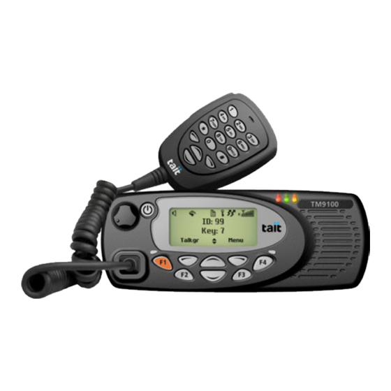
Tait TM9100 User Manual (104 pages)
Brand:
Tait
| Category:
Two-Way Radio
| Size: 2 MB
Table of Contents
Directive 1999/5/CE Declaration of Conformity
3
Updates of Manual and Equipment
4
For Your Safety
6
Compliance with Rf Energy Exposure Standards
7
Declaration of Conformity
9
Interference with Electronic Devices
10
Potentially Explosive Atmospheres and Blasting Areas
10
High Radio Surface Temperatures
12
Menu Map
13
Radio Controls
14
Table of Contents
15
1 About this Guide
18
Safety Warnings Used in this Guide
18
Related Documentation
18
2 Getting Started
19
About Your Digital Radio
20
Lack of Static Noise
20
Coverage
20
About the Radio Controls
21
About the Keypad Microphone
22
About the Hand-Held Control Head
23
Understanding the Radio Display
24
Radio Display Symbols
24
Understanding the Radio Indicators
25
Status Indicators
25
Audible Tones
26
3 Basic Operation
27
Turning the Radio on and off
28
Turning the Radio on and off Using a Hand-Held Control Head
28
Adjusting the Speaker Volume
29
Adjusting the Volume Using a Hand-Held Control Head
29
Locking and Unlocking the Keypad
29
Navigating the Radio's Menus
30
Using the Main Menu
30
Accessing Frequently Used Menus
30
Using Function Keys to Access Frequently Used Features
32
Viewing the Function Key Settings
32
Selecting a Zone
33
Selecting a Channel
34
Limiting Call Time
34
Checking Recent Calls
35
About GPS Information
36
About GPS Status Information
36
Viewing GPS Information
36
4 Operating in Conventional Mode
38
Making Calls
39
Making an Individual Call
39
Understanding Talkgroups
40
Making an Emergency Call
41
Receiving Calls
42
Identifying a Caller (Talking Party ID)
42
Receiving a Two-Tone Call
43
Communicating Directly with Other Radios
44
Checking that the Channel Is Clear
45
Turning Monitor on and off
45
Using the Radio in Different Repeater Areas
46
Selecting a Voting Group
46
Suspending a Channel from a Voting Group
47
Scanning a Group of Channels
48
Activating Standard Scanning
49
Activating Background Scanning
49
Activating In-Zone Scanning
50
Making a Call While Scanning
50
Suspending a Channel from a Scan Group
51
Editing a Scan Group
52
Selecting a Group to Edit
52
Viewing Group Membership
53
Adding a Channel to a Group
54
Deleting a Channel from a Group
54
Changing a Group's Transmit Channel
55
Changing a Group's First or Second Priority Channel
55
Hearing Faint and Noisy Signals
56
Turning Squelch Override on and off
56
5 Operating in P25 Trunking Mode
57
About P25 Trunking
58
Checking that the System Is Available
58
Failsoft Operation
59
Making a Talkgroup Call
60
Receiving a Talkgroup Call
62
Scanning a Group of Talkgroups
63
Activating Talkgroup Scanning
63
Suspending a Channel from a Talkgroup Scan Group
63
Editing a Talkgroup Scan Group
64
Making an Individual Call
65
Receiving an Individual Call
66
Emergency Calls
66
Making a Phone Call
67
Unconnected Calls
68
Failsoft Mode Operation
69
Dynamic Regrouping
70
6 Safeguarding You and Your Radio
71
About Locking the Radio
72
Locking the Radio
72
Unlocking the Radio
72
About Emergency Calls
73
Making a Priority Call
73
Understanding Emergency Mode
74
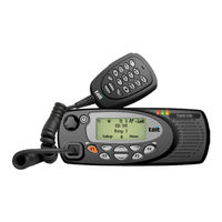
Tait TM9100 User Manual (91 pages)
Brand:
Tait
| Category:
Transceiver
| Size: 2 MB
Table of Contents
Updates of Manual and Equipment
3
For Your Safety
5
Compliance with Rf Energy Exposure Standards
6
Radio Frequency Emissions Limits in the Usa
7
Unapproved Modifications or Changes to Radio
7
Frequency Band Reserved for Distress Beacons
7
Safe Radio Operation
7
Interference with Electronic Devices
8
Menu Map
9
Radio Controls
10
Table of Contents
11
1 About this Guide
14
Safety Warnings Used in this Guide
14
Related Documentation
14
2 About Your Radio
15
About Your Digital Radio
16
Lack of Static Noise
16
Coverage
16
Basic Operation
17
Turning Your Radio on and off
18
Adjusting the Volume
18
About the Press-To-Talk (PTT) Key
19
Radios with a Hand-Held Control Head
20
Using Function Keys to Access Frequently Used Features
21
Emergency Key
21
Understanding the Radio Display
22
Using the Menus to Access Settings and Features
23
Selection Keys
23
Scroll Keys
23
Accessing the Main Menu
24
Accessing Frequently Used Menus
24
Understanding the Radio Indicators
26
Audible Tones
26
Status Indicators
28
3 Making and Receiving Calls
29
Making Calls
30
Selecting a Zone
31
Selecting a Channel
32
Understanding Talkgroups
33
Making an Emergency Call
34
Making an Individual Call
34
Receiving Calls
35
Identifying a Caller (Talking Party ID)
35
Communicating Directly with Other Radios
36
Checking Your Recent Calls
37
Checking that the Channel Is Clear (Monitor)
38
Turning Monitor on and off
38
Call Alert Paging
39
Checking Whether a Radio Is Available
40
4 Listening to Channel Traffic
41
Selecting a Voting or Scan Group
42
Using Your Radio in Different Repeater Areas
44
Suspending a Channel from a Voting Group
44
Scanning a Group of Channels
45
Understanding the Different Types of Scanning
45
Making a Call While Scanning
45
Suspending a Channel from a Scan Group
46
Editing a Background Scan Group
47
Hearing Faint and Noisy Signals
49
Turning Squelch Override on and off
49
5 Sending and Receiving Messages
50
About Messages
51
Sending a Message
51
Informing Other Radio Users of Your Status
53
Requesting a Status Update
54
6 Safeguarding You and Your Radio
55
About Locking Your Radio
56
Locking Your Radio
56
Unlocking Your Radio
56
Making a Radio Inoperable
57
Sending a Radio Inhibit Request
57
Sending a Radio Uninhibit Request
58
Radio Monitor
59
Sending a Radio Monitor Request
59
About Encryption
60
Encrypting Your Calls
60
Making an Encrypted Call
61
Receiving an Encrypted Call
61
Changing Your Radio's Encryption Key
62
Removing Encryption Keys from Your Radio
63
About Emergency Calls
65
Making a Priority Call
65
Understanding Emergency Mode
66
Advertisement
Tait TM9100 Tune Up And Inspection (39 pages)
Tuneup info for compliance
Brand:
Tait
| Category:
Radio
| Size: 0 MB
Table of Contents
Table of Contents
2
1 General Information
4
2 Calibration Basics
18
Calibrating the Radio
18
Using the Calibration Application
19
Sliders
19
Option Buttons
19
Instruction Boxes
20
Radio Model Toolbar
20
Specifications Form
20
Viewing Calibration Test Results
21
Viewing Calibration Files
21
3 Calibration Tests
22
AD6521 Volt Ref
22
TCXO/VCO Mod Dev
22
Receiver
23
Mute
24
Final Gate Bias and Tx Driver Bias Limit
24
Final Gate Bias 1
25
Final Gate Bias 2
25
Tx Driver Bias Limit
25
Tx Power Cycle
26
Tx Power Control
26
4 Deviation and Squelch Thresholds
27
Deviation Settings Tab
27
Squelch and Signalling Thresholds Tab
28
Advanced Tab
29
5 Raw Data Reference
30
Volt Ref/Tcxo/Vco/Vcxo Tab
30
VCO Auto Cal Check Tab
30
Receiver Tab
30
Mute Tab
31
Tx Gate Biasing Tab
31
Power Tab
32
Test Freqs Tab
32
6 TOPA-SV-024 Test Unit
34
Test Equipment Setup
34
Operation
34
TOP / TM9000 Switch
36
TOP Mod Audio / off / MIC Audio Switch
36
Hook on / Hook off Switch
36
Rx / Tx/Ptt Switch
37
Speaker / Radio / Load Switch
37
PCB Information (PCB IPN 220-01418-02A)
38
Parts List (Rev. 4)
38
PCB Layout
38
Circuit Diagram
39
Tait TM9100 Installation Manual (29 pages)
Brand:
Tait
| Category:
Radio
| Size: 0 MB
Table of Contents
Contact Information
2
Table of Contents
3
Preface
4
Scope of Manual
4
Enquiries and Comments
4
Updates of Manual and Equipment
4
Copyright
4
Disclaimer
5
Associated Documentation
5
Document Conventions
5
Safety Warnings
7
RF Exposure Hazard
7
Safe Radio Mounting
7
Interference with Vehicular Electronics
8
Preparation When Drilling Holes
8
Vehicles Powered by Liquefied Petroleum Gas
8
Radio Installation in Gas or Fuel Tankers
8
Non-Standard Radio Installations
9
Negative Earth Supply
9
1 Preparing the Installation
10
Regulations
10
Installation Tools
10
Checking the Equipment for Completeness
10
Choosing an Installation Configuration
11
2 Installing the Radio
13
Mounting and Removing the Control Head
13
Selecting the Mounting Position
15
Mounting the U-Bracket
16
Installing the Antenna
17
Connecting the Power Cable to the Power Source
18
Connecting a Remote Speaker
20
Connecting to the Auxiliary Connector (Ignition Signal, Emergency Switch, External Alert Devices)
20
Installing the Radio
24
Installing the Microphone
25
Checking the Installation
26
Tait General Software Licence Agreement
27
Tait Electronics Limited August
29
Tait TM9100 User Manual (22 pages)
Brand:
Tait
| Category:
Radio
| Size: 0 MB
Table of Contents
For Your Safety
3
Using this Radio
3
Controlling Your Exposure to RF Energy
3
Compliance with RF Energy Exposure Standards
4
Radio Frequency Emissions Limits in the USA
4
Unapproved Modifications or Changes to Radio
5
Interference to Radio Communications
5
Frequency Band Reserved for Distress Beacons
5
Safe Radio Operation
5
Interference with Electronic Devices
6
High Temperatures
6
Radio Protection
6
Table of Contents
7
1 About this Guide
9
Document Conventions
9
Safety Symbols Used in this Guide
9
Feedback about this Manual
9
Copyright Information
10
Disclaimer
10
2 About Your Radio
11
About Your Digital Radio
12
Lack of Static Noise
12
Coverage
12
Basic Operation
13
Turning Your Radio On/Off
14
Adjusting the Volume
14
Making Calls
14
About the Press-To-Talk (PTT) Key
15
Using Keys to Access Commonly Used Features
16
Emergency Key
16
Viewing Your Function Key Settings
16
Understanding the Radio Display
17
Display Symbols
17
Using the Menus to Access Settings
18
Selection Keys
18
Scroll Keys
18
Accessing Menus
19
Accessing Frequently Used Menus
19
Using the Scroll Key Quick Access Menu
19
Using the Left Selection Key Quick Access Menu
20
Understanding the Radio Indicators
21
Alert Tones
21
Status Indicators
22
Tait TM9100 Installation Manual (26 pages)
110W Mobile Radios
Brand:
Tait
| Category:
Radio
| Size: 0 MB
Table of Contents
Contact Information
2
Table of Contents
3
Preface
4
Scope of Manual
4
Associated Documentation
4
Publication Record
4
Document Conventions
5
Safety Warnings
6
RF Exposure Hazard
6
Safe Radio Mounting
6
Correct Fuse Rating
6
Interference with Vehicular Electronics
7
Preparation When Drilling Holes
7
Vehicles Powered by Liquefied Petroleum Gas
7
Radio Installation in Gas or Fuel Tankers
7
Negative Earth Supply
7
1 Introduction
9
2 Preparing the Installation
10
Regulations
10
Installation Tools
10
Checking the Equipment for Completeness
10
Programming Settings
11
3 Installing the Radio
12
Selecting the Mounting Position
12
Installing the Antenna
13
Connecting the Power Cable to the Power Source
14
Installing the Remote Control Head
15
Installing the Microphone
16
Connecting to the Ignition Signal
17
Connecting a Remote Speaker
18
Connecting to an Emergency Switch And/Or External Alert Devices
19
Mounting the Radio
21
Checking the Installation
22
Tait Software License Agreement
23
Tait TM9100 Installation Manual (24 pages)
40 W/50 W
Brand:
Tait
| Category:
Radio
| Size: 0 MB
Table of Contents
Contact Information
2
Table of Contents
5
Preface
6
Scope of Manual
6
Enquiries and Comments
6
Updates of Manual and Equipment
6
Copyright
6
Disclaimer
6
Document Conventions
7
Safety Warnings
8
1 Preparing the Installation
11
Regulations
11
Installation Tools
11
Choosing an Installation Configuration
12
2 Installing the Radio
13
Mounting and Removing the Control Head
13
Selecting the Mounting Position
15
Mounting the Radio
16
Installing the Microphone
17
Installing the Antenna
18
Connecting the Power Cable
19
Connecting a Remote Speaker
21
Connecting to the Auxiliary Connector
21
Checking the Installation
24
Tait TM9100 Safety Information Manual (15 pages)
Brand:
Tait
| Category:
Radio
| Size: 0 MB
Table of Contents
Copyright and Trademarks
2
Intellectual Property Rights
2
To Our European Customers
3
About this Booklet
4
Radio Frequency Exposure Information
4
Using this Radio
4
Controlling Your Exposure to RF Energy
5
Compliance with RF Energy Exposure Standards
6
Radio Frequency Emissions Limits in the USA
7
Unapproved Modifications or Changes to Radio
7
Low-Power Channels
8
Use of Encryption
8
Frequency Band Reserved for Distress Beacons
8
Safe Radio Operation
9
Interference with Electronic Devices
9
High Radio Surface Temperatures
10
Radio Protection When Changing the Vehicle Battery
10
Tait Licence Agreement
11
Important Notice
11
Title to Software
11
Limited Warranty
12
Law and Jurisdiction
14
No Other Terms
14
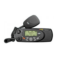
Tait TM9100 User Manual (4 pages)
Brand:
Tait
| Category:
Portable Radio
| Size: 0 MB
Advertisement
Related Products
Tait TM9100 Series P25
Tait TM9155R
Tait TM9155
Tait TM9300
Tait TM9300 DMR
Tait TM9400 Series P25
Tait TM9400
Tait TM9456
Tait TM9315
Tait TM9356
Tait Categories
Radio
Accessories
Portable Radio
Two-Way Radio
Repeater
More Tait Manuals
Login
Sign In
OR
Sign in with Facebook
Sign in with Google
Upload manual
Upload from disk
Upload from URL