Sign In
Upload
Manuals
Brands
Siemens Manuals
Control Unit
Milltronics BW500/L
Siemens Milltronics BW500/L Manuals
Manuals and User Guides for Siemens Milltronics BW500/L. We have
2
Siemens Milltronics BW500/L manuals available for free PDF download: Operating Instructions Manual, Operating Lnstructions
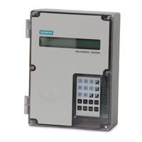
Siemens Milltronics BW500/L Operating Instructions Manual (220 pages)
Integrators
Brand:
Siemens
| Category:
Control Unit
| Size: 8.6 MB
Table of Contents
Table of Contents
5
Safety Notes
13
The Manual
15
Milltronics BW500 and BW500/L
17
Specifications
19
Installation
23
Dimensions
23
Layout
25
Optional Plug-Ins
27
Smartlinx Module
27
Ma I/O Board
27
LVDT Conditioner Card
28
Optional Components and Their Locations
29
Interconnection
29
System Diagram
30
Scale - One Load Cell
31
Scale - Two Load Cells
32
Scale - Four Load Cells
34
Scale - Six Load Cells
35
Scale - LVDT
36
Speed
37
Constant Speed (no Sensor)
37
Main Speed Sensor
38
Auxiliary Speed Sensor
39
Auxiliary Inputs
40
Auto Zero
40
RS232 Port 1
41
Printers
41
Computers and Modems
41
Remote Totalizer
42
Ma Output 1
42
Relay Output
42
RS485 Port 2
43
Daisy Chain
43
Terminal Device
43
RS232 Port 3
43
Power Connections
44
Ma I/O Board Connections
45
Installing/Replacing the Back-Up Battery
46
Start up
49
Keypad
49
Program Mode
50
Program Mode Display
50
To Enter PROGRAM Mode
51
RUN Mode
53
Initial Start up
53
Power up
54
Programming
54
Load Cell Balancing
59
Typical Two Load Cell Belt Scale
60
Access P295
60
Balancing Six Load Cell Belt Scales
64
Balancing for a and B
64
Balancing for C and D
64
Zero Calibration
65
RUN Mode
67
Recalibration
69
Belt Speed Compensation
69
Access P018
69
Material Tests
70
Change
71
Access P019 and Enter EDIT Mode
72
Material Test
72
Design Changes
74
Recalibration
74
Routine Zero
74
Initial Zero
76
Direct Zero
77
Auto Zero
78
Routine Span
79
Initial Span
80
Direct Span
82
Multispan
83
Programming
84
Online Calibration
87
Online Calibration Feature
88
Activate Online Calibration
90
Factoring
92
Access P359 in VIEW Mode
93
Linearization
94
Operation
99
Load Sensing
99
Speed Sensing
99
Differential Speed Detection
100
Moisture Compensation
100
Incline Compensation
101
Modes of Operation
102
Damping
102
Ma I/O (0/4-20 Ma)
103
Relay Output
104
Totalization
105
Internal Totalizer
105
External Totalizer
106
PID Control
109
Hardware
109
Connections
109
Setpoint Controller - Rate Control
110
Setpoint Controller - Load Control
111
Setpoint Controller - Master/Slave Control
112
Setpoint Controller - Rate and Load Control
113
Setup and Tuning
114
Proportional Control (Gain), P
114
Integral Control (Automatic Reset), I
114
Derivative Control (Pre-Act or Rate), D
115
Feed Forward Control, F
115
PID Setup and Tuning
116
Initial Start-Up
116
Programming
119
Batching
123
Connections
124
Typical Ladder Logic
124
Programming
125
Operation
125
Pre-Act Function
126
Communications
127
BW500 and BW500/L and Smartlinx
127
Connections
128
Wiring Guidelines
128
Configuring Communication Ports
129
P770 Serial Protocols
129
P771 Protocol Address
130
P772 Baud Rate
130
P773 Parity
130
P774 Data Bits
131
P775 Stop Bits
131
P778 Modem Attached
131
P779 Modem Idle Time
132
P780 RS-232 Transmission Interval
132
P781 Data Message
133
P799 Communications Control
133
Dolphin Protocol
134
Modbus RTU/ASCII Protocol
135
How Modbus Works
135
Modbus RTU Vs. ASCII
136
Modbus Format
136
Modbus Register Map
136
Modbus Register Map (Cont'D)
140
Modems
149
Example Setup
149
Error Handling
151
Parameters
155
Start up (P001 to P017)
155
P001 Language
155
P002 Test Reference Selection
155
P003 Number of Load Cells
156
P004 Rate Measurement System
156
P005 Design Rate Units
156
P008 Date
156
P009 Time
157
P011 Design Rate
157
P014 Design Speed
157
P015 Speed Constant
157
P016 Belt Length
158
P017 Test Load
158
P018 Speed Adjust
159
P019 Manual Span Adjust
159
P022 Minimum Speed Frequency
159
P080 Display Damping
159
P081 Display Scroll Mode
160
Relay/Alarm Function (P100 - P117)
160
P100 Relay Function
160
P101 High Alarm / Deviation Alarm
161
P102 Low Alarm
161
P107 Relay Alarms
161
P117 Relay Dead Band
162
P118 Relay Logic
162
P119 Override
162
Ma I/O Parameters (P200 - P220)
163
P200 Ma Output Range
163
P201 Ma Output Function
163
P204 Ma Output Average
163
P212 Ma Output Minimum
164
P213 Ma Output Maximum
164
P214 4 Ma Output Trim
164
P215 20 Ma Output Trim
164
P220 Ma Output Damping
164
P250 Ma Input Range
165
P255 Ma Input Function
165
P261 4 Ma Input Trim
165
P262 20 Ma Input Trim
166
P270 Auxiliary Input Function
167
Calibration Parameters (P295 - P360)
169
P295 Load Cell Balancing
169
P341 Days of Service
169
P350 Calibration Security
170
Online Calibration Options (P355 - P358)
170
P355 Online Calibration Feature
170
P356 Online Calibration Reference Weight
170
P357 Online Calibration Limits
171
P358 Online Calibration Activation
171
P359 Factoring
171
P360 Calibration Duration
171
P365 Multispan
172
P367 Direct Zero Entry
172
P368 Direct Span Entry
172
P370 Zero Limit Deviation
173
P371 Auto Zero Initiation Upper Limit
173
P377 Initial Zero
173
P388 Initial Span
173
Linearization Parameters (P390 - P392)
174
P390 Linearizer
174
P391 Linearizer Load Points
174
P392 Linearizer Compensation
174
P398-01 Moisture Content
174
P398-02 Moisture Content
174
P399 Incline Sensing
175
Proportional Integral Derivative (PID) Control
175
P400 PID System
175
P401 PID Update Time
175
P402 PID Process Value Source
176
P405 Proportional Term
176
P406 Integral Term
176
P407 Derivative Term
176
P408 Feed Forward Term
176
P410 Manual Mode Output
177
P414 Setpoint Configuration
177
P415 Local Set Point Value
177
P416 External Setpoint
178
P418 Remote Setpoint Ratio
178
P419 PID Freeze Option
178
Batch Control (P560 - P568)
178
P560 Batch Mode Control
178
P564 Batch Setpoint
179
P566 Batch Pre-Warn
179
P567 Batch Pre-Warn Setpoint
179
P568 Batch Pre-Act
179
P569 Manual Batch Pre-Act Amount
180
P598 Span Adjust Percentage
180
Totalization (P619 - P648)
180
P619 Totaling Dropout
180
P620 Display Zero Dropout
180
P621 Ma Zero Dropout
181
P631 Totalizer Resolution
181
P634 Communication Totalizer Resolution
182
P635 Verification Totalizer
182
P638 External Totalizer Resolution
183
P643 External Contact Closure
184
P647 Totalizer Display
184
P648 Totalizer Reset, Internal
184
P680 Test Load: Weight (Options)
185
P681 Total Mass of Test Weights
185
P682 Average Idler Spacing
185
P690 Speed Constant Entry
185
P691 Drive Pulley Diameter
186
P692 Pulses Per Sensor Revolution
186
Ecal Parameters (P693 - P698)
186
P693 Load Cell Capacity Units
186
P694 Ecal Load Cell Capacity
186
P695 Ecal Load Cell Sensitivity
187
P696 Ecal Load Cell Excitation
187
P697 Ecal Idler Spacing
187
P698 Ecal Conveyor Inclination
187
P699 Ecal MV Span
188
P735 Back Light
188
P739 Time Zone
188
Communication (P740 - P799)
189
P742 Word Order Parameter
189
P750 - P769 Smartlinx Module Specific Parameters
189
P770 - P789 Local Port Parameters
189
Smartlinx Hardware Testing
189
P790 Hardware Error
190
P791 Hardware Error Code
190
P792 Hardware Error Count
190
P794 Smartlinx Module Type
190
P795 Smartlinx Protocol
191
P799 Communications Control
191
Test and Diagnostic (P900 - P951)
191
P900 Software Revision
191
P901 Memory Test
191
P911 Ma Output Test
192
P914 Ma Input Value
192
P918 Speed Input Frequency
192
P931 Running Totalizer
192
P940 Load Cell MV Signal Test
193
P943 Load Cell A/D Reference
193
P948 Error Log
193
P950 Zero Register
193
P951 Span Register
193
P952 Design Load
194
P999 Master Reset
194
Troubleshooting
195
Generally
195
Specifically
195
Certification
199
Parameters Unlocked When Certification Switch Is Set
199
Certification Printing
200
Appendix
201
Memory Backup
201
Software Updates
201
Calibration Criteria
201
Appendix II
202
Technical Support
207
Glossary
209
Index
213
Advertisement
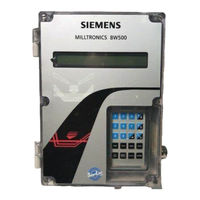
Siemens Milltronics BW500/L Operating Lnstructions (170 pages)
Brand:
Siemens
| Category:
Measuring Instruments
| Size: 1.62 MB
Table of Contents
Table of Contents
3
Safety Notes
7
The Manual
7
Technical Support
8
Milltronics BW500 and BW500/L
9
Milltronics BW500
9
Milltronics BW500/L
9
Milltronics BW500 and BW500/L Features
9
Specifications
11
Installation
15
Dimensions
15
Layout
17
Optional Plug-Ins
18
Smartlinx7 Module
18
Ma I/O Board
18
Interconnection
20
System Diagram
20
Scale - One Load Cell
21
Scale - Two Load Cells
22
Scale - Four Load Cells
23
Scale - Six Load Cells
24
Scale - LVDT
25
Speed
26
Constant Speed (no Sensor)
26
Main Speed Sensor
26
Auxiliary Speed Sensor
27
Auxiliary Inputs
28
Auto Zero
28
Port 1
28
Printers
28
Computers and Modems
29
Remote Totalizer
29
Ma Output 1
29
Relay Output
30
Port 2
31
Daisy Chain
31
Terminal Device
31
Port 3
31
Power Connections
32
Ma I/O Board Connections
33
Installing/Replacing the Back-Up Battery
33
Start up
34
Keypad
34
PROGRAM Mode
35
PROGRAM Mode Display
35
To Enter PROGRAM Mode
35
RUN Mode
37
Initial Start up
37
Power up
37
Programming
37
Press
38
Load Cell Balancing
41
Typical Two Load Cell Belt Scale
41
Zero Calibration
44
RUN Mode
46
Recalibration
47
Belt Speed Compensation
47
Material Tests
48
Change
48
Material Test
50
Design Changes
51
Recalibration
51
Routine Zero
51
Initial Zero
52
Direct Zero
53
Auto Zero
53
Routine Span
54
Initial Span
55
Direct Span
56
Multispan
56
Online Calibration
59
Factoring
64
Linearization
65
Operation
69
Load Sensing
69
Speed Sensing
69
Differential Speed Detection
69
Moisture Compensation
70
Incline Compensation
71
Modes of Operation
71
Damping
72
Ma I/O (0/4-20 Ma)
72
Relay Output
73
Totalization
74
PID Control
77
Hardware
77
Connections
77
Setpoint Controller - Rate Control
78
Setpoint Controller - Load Control
78
Setpoint Controller - Master/Slave Control
79
Setpoint Controller - Rate and Load Control
80
Setup and Tuning
80
Proportional Control (Gain), P
80
Integral Control (Automatic Reset), I
81
Derivative Control (Pre-Act or Rate), D
82
Feed Forward Control, F
82
PID Setup and Tuning
83
Initial Start-Up
83
Programming
86
Batching
89
Connections
90
Typical Ladder Logic
90
Programming
90
Operation
91
Pre-Act Function
91
Communications
92
BW500 and BW500/L and Smartlinx
93
Connection
93
Wiring Guidelines
93
Configuring Communication Ports
94
P770 Serial Protocols
94
P771 Protocol Address
95
P772 Baud Rate
95
P773 Parity
95
P774 Data Bits
96
P775 Stop Bits
96
P778 Modem Attached
96
P779 Modem Idle Time
97
P780 RS-232 Transmission Interval
97
P781 Data Message
98
P799 Communications Control
98
Dolphin Protocol
99
Dolphin Plus Screen Shot
99
Modbus RTU/ASCII Protocol
100
How Modbus Works
100
Modbus RTU Vs. ASCII
101
Modbus Format
101
Modbus Register Map
101
Modbus Register Map (Cont' D )
104
Text Messages
112
Modems
113
Error Handling
115
Parameters
117
Start up (P001 to P017)
117
Relay/Alarm Function (P100 - P117)
122
Ma I/O Parameters (P200 - P220)
125
Calibration Parameters (P295 - P360)
131
Online Calibration Options (P355 to P358)
132
Linearization Parameters (P390 - P392)
135
Proportional Integral Derivative (PID) Control Parameters (P400 - P419)
136
Batch Control (P560 - P568)
140
Totalization (P619 - P648)
142
Ecal Parameters (P693 - P698)
147
Communication (P740 - P799)
149
Smartlinx Hardware Testing
149
Test and Diagnostic (P900 - P951)
151
Troubleshooting
154
Generally
154
Specifically
154
Error Codes
155
Certification
156
Parameters Unlocked When Certification Switch Is Set
156
Certification Printing
157
Glossary
158
Memory Backup
161
Software Updates
161
Calibration Criteria
161
Zero
161
Span
161
PID Systems
161
Appendix I
161
Appendix II: Software Revision History
162
Index
166
Advertisement
Related Products
Siemens Milltronics BW500
Siemens Milltronics BW100
Siemens BestSound Ace micon
Siemens BPZ:LME39.100C1
Siemens BF634LGS1
Siemens SIMOGEAR BA 203-K2
Siemens BD2-AK3M2/F Series
Siemens BE550LM 0I Series
Siemens BI630CN 1 Series
Siemens BF425LM 0 Series
Siemens Categories
Industrial Equipment
Controller
Control Unit
Oven
Washer
More Siemens Manuals
Login
Sign In
OR
Sign in with Facebook
Sign in with Google
Upload manual
Upload from disk
Upload from URL