Sign In
Upload
Manuals
Brands
quanergy Manuals
Accessories
M8
quanergy M8 Manuals
Manuals and User Guides for quanergy M8. We have
1
quanergy M8 manual available for free PDF download: User Manual
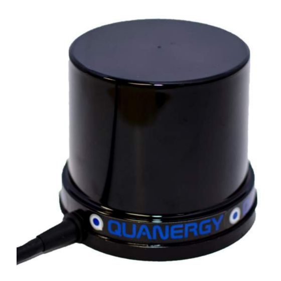
quanergy M8 User Manual (90 pages)
Brand:
quanergy
| Category:
Accessories
| Size: 3.29 MB
Table of Contents
Notices
2
Contact
2
Follow Us
2
Revision History
3
Table of Contents
5
Contents
5
Figures
9
Tables
10
Important Safety Notices
11
Caution
11
Operating Safety
11
Physical Safety
11
Compliances
12
Astm G154
12
CE Compliance
12
FCC Compliance
12
FDA Compliance
12
IEC/EN Safety Compliance
13
IP69K Compliance
13
Rohs Compliance
13
WEEE Compliance
13
1 Getting Started
14
M8 Sensor
14
Figure 1. Sensor Manufacturing Labels
14
Table 1. M8 Sensor
14
Complete Minimal Working System
15
Interface Cable
15
Figure 2. Sensor Interface Cable Provided with M12 IP67-Rated Female Connector
15
Power Source
16
Figure 3. AC/DC Power Adapter (Bottom) and Cable (Top)
16
Power Supply
16
Proper Disconnect
16
Table 2. AC/DC Power Adapter Specifications
16
Power over Ethernet
17
Computing Environment with Tools and Solutions
17
User-Provided Items
18
Support Documents
18
Table 3. User-Provided Items
18
2 Introducing the Sensor
19
Applications
19
Features
19
Models
19
NMEA and PPS Inputs
19
Figure 4. M8 Lidar Sensor
19
Multiple Returns
20
Evaluation Rules
20
Figure 5. Sensor Emitting a Single Beam (for Example) with Multiple Returns
20
Intensity
21
Figure 6. Point Cloud Produced by M8 Sensor Rev D5 Reveals Intensity
21
3 Mounting the Sensor
22
Figure 7. Permanent Mounting Base (Round), Detachable Base Plate (Rectangular)
22
Options
23
Scenarios
23
Figure 8. Vehicle Grill-Mounted Sensor
23
Vehicle Grill-Mounted Scenario
23
Figure 10. Indoor Tripod-Mounted Sensor with Detachable, Rectangular Base Plate
24
Figure 9. Vehicle Rack-Mounted Sensor with User's Custom Base Plate
24
Indoor Tripod-Mounted Scenario
24
Vehicle Rack-Mounted Scenario
24
Figure 11. Drone with Side-Mounted Sensor
25
Figure 12. Wall-Mounted for Security
25
Side-Mounted on Drone Scenario
25
Wall-Mounted Security Scenario
25
Figure 13. Multi-Sensor Scenario
26
Multi-Sensor Scenario
26
Connectors and Pins
27
Figure 14. Sensor Cable M19 (Left), Interface M19 (Center), Interface Sub-Cables (Right)
27
Figure 15. Sensor Cable Connector Wire Color (Left), J1/J2/Sub-Cable Connectivity (Right)
27
Figure 16. M19 Pinout and Photo
28
Figure 17. M12 3-Pin Pinout and Photo
28
4 Integrating the Sensor
29
Connect the Sensor
29
Figure 18. Sensor Connections with Static IP Address
29
Figure 19. Sensor Connections with Dynamic IP Address
30
Find the Serial Number and IP Address
31
Hardware Label Reveals Serial Number
31
Q-View Software Reveals Serial Number and IP Address
31
Figure 20. Sensor Serial Number on Detachable Base Plate (Left), Mounting Base (Right)
31
M8 Sensor Settings Management Application Reveals Serial Number and Versions
32
Terminal Command Reveals Serial Number and IP Address
32
Figure 21. Finding the Sensor IP Address from the Command Line, Pinging Sensor
32
5 Getting TCP Ethernet Packets
33
Variable Definitions
33
For All Three Returns
34
Table 4. Variable Definitions for M8 Packet
34
Table 5. Variable Definitions for the Packet Data
34
For Reduced Return
35
Table 6. Variable Definitions for M8 Packet
35
Table 7. Variable Definitions for the Packet Data
35
Timestamp
36
Laser Firing
36
Beam Angles
36
Figure 22. Laser Beam Angles
36
Figure 23. Laser Firing Position (Top-Down View)
37
6 Managing the Sensor
38
Table 8. Features Introduced in each Revision of the Sensor (M8) and Web Server (WS)
38
Introducing the Web Server
39
Opening the Web Server
40
Figure 24. Creating a Network on Non-Ubuntu Machine
40
Figure 25. Creating a Network on Windows 7 Machine
41
M8 Sensor Tab
42
Figure 26. Web Server: M8 Sensor Tab's Login Mode
42
Login
42
Figure 27. Web Server: M8 Sensor Tab's Welcome Mode
43
Welcome
43
Settings Tab
44
Edit Settings
44
Figure 28. Web Server: Settings Tab's Menu Items
44
Frame Rate
44
Figure 29. Web Server: Settings Tab's M8 Settings Edit (Top), Rings (Right), GPS (Bottom)
45
Figure 30. Usage-Based Sensor Placement Improves Results
46
Scan Field
46
Low Power Spinup
47
Table 9. Web Server: Scan Field Specifications Based on Sensor Placement
47
Return Data Select
48
Ring Settings
48
GPS Settings
49
Figure 31. Web Server: Settings Tab's Reset Message (Left), Reboot Message (Right)
50
Reset Settings
50
Edit Network
51
Admin Tab
52
Figure 33. Web Server: Admin Tab
52
My Account Tab
53
Change Password
53
Figure 34. Web Server: My Account Tab's Change Password and Editor Logout Items
53
Figure 35. Web Server: My Account Tab's Change Passwords Fields
53
Editor Logout
54
Status Tab
54
Figure 36. Web Server: M8 Status Tab
54
Figure 37. Web Server: M8 Sensor Status Tab's Report
55
Versions Tab
56
Figure 38. Web Server: Versions Tab's Report of Associated Software
56
Table 10. Web Server: M8 Software Version Definitions
57
Reboot Tab
58
Figure 39. Web Server: Reboot Tab's Confirmation Page
58
Reset a Static IP Address
59
Figure 40. Creating a Network Environment for Fail Safe Mode
59
Closing the Web Server
60
7 Taking the Next Steps
61
8 Stopping the Sensor
61
Shut down
61
Restart
61
9 Troubleshooting Issues
62
Check the Status
62
Table 11. Web Server: M8 Software Status Definitions
62
Perform Cleaning
64
Resolve an Issue
64
Check an Issue
64
Figure 41. Power Indicator on the AC/DC Power Adapter
64
Report an Issue
65
Figure 42. View Sensor through IR Scope (Left) to See Sensor Flash+Reflection (Right)
65
Appendix 1: Use of NMEA/PPS Signals
66
Concepts and Specifications
66
Purpose of NMEA
66
Purpose of PPS
67
Electrical Interface and Transmission Settings
67
Table 12. Electrical and Transmission Specifications
67
Mechanical Interface
68
Figure 43. NMEA/PPS Input Voltages
68
Figure 44. Nmea/Pps/Ground Communication
68
Data Communication
69
GPRMC NMEA Sentence
69
Table 13. NMEA $GPRMC Sentence Decoded
69
GPZDA NMEA Sentence
70
Table 14. NMEA $GPZDA Sentence Decoded
70
Procedures
71
Connect Single Sensor to the GPS Receiver
71
Figure 45. NMEA/PPS Signals Synchronized on Single Sensor
71
Connect Multiple Sensors to the GPS Receiver
72
Figure 46. NMEA/PPS Signals Synchronized on Multiple Sensors
72
Figure 47. NMEA/PPS Signals Distributed by PRL-414B-BNC Buffer Amplifier
72
Configure the GPS Settings
73
Figure 48. Normal Alignment: Positive PPS (Top), Active Low NMEA (Bottom)
73
Figure 49. Web Server: GPS Settings
73
Baud Rate Synchronization
74
NMEA Signal
74
PPS Signal
74
Synchronize Sensor with GPS Timestamp
74
Ubuntu with ROS Driver
74
Windows or Ubuntu Without ROS Driver
74
Check the GPS Signal Lock
76
Figure 50. Web Server: Status Tab Report for GPS and UTC Timestamp
76
For M8 Sensor Rev D5
76
Appendix 2: Sensor Mounting and Accessories
77
Sensor Dimensions
77
Figure 51. M8 Sensor Mounting Drawing of Sensor
77
Base Plate Dimensions
78
Accessory for Mounting
78
Figure 52. M8 Sensor Mounting Drawing of Rectangular Base Plate
78
Figure 53. M8 Sensor Adjustable Mount Accessory
78
Accessory for Weather Shielding
79
Figure 54. M8 Sensor Weather Shield Accessory
79
Installation of Accessories
80
Gather Resources
80
Apply Force
80
Determine Which Mounting Surface
80
Figure 55. Adjustable Mount's Pole Clamp
81
Mounting to a Pole
81
Figure 56. Adjustable Mount's Back Plate
82
Mounting to a Flat Surface
82
Address Environmental Concerns
83
Figure 57. Weather Shield Installation
83
With the Adjustable Mount
83
Without the Adjustable Mount
83
Add the Sensor
84
Adjust Pitch and Roll
84
Pitch Adjustment
84
Roll Adjustment
84
Figure 58. Adjustable Mount's Roll Adjustments
85
Figure 59. Adjustable Mount's Pitch Adjustments
85
Appendix 3: Frequently Asked Questions
86
Index
88
Advertisement
Advertisement
Related Products
quanergy Categories
Desktop
Server
Accessories
More quanergy Manuals
Login
Sign In
OR
Sign in with Facebook
Sign in with Google
Upload manual
Upload from disk
Upload from URL