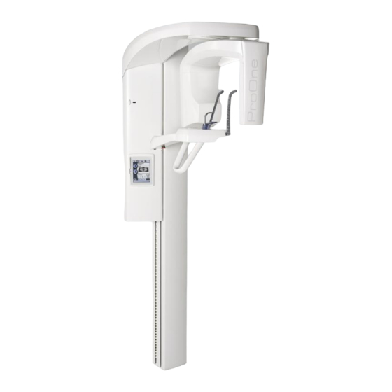
Planmeca ProOne Calibration Manual
Hide thumbs
Also See for ProOne:
- Technical manual (195 pages) ,
- User manual (116 pages) ,
- Manual (57 pages)

Related Manuals for Planmeca ProOne


Summary of Contents for Planmeca ProOne
- Page 1 PLANMECA ProOne Calibration Manual Printed copies of this document are considered uncontrolled. 7535.11.Rev001 08.07.2018...
- Page 2 IEC364. Equipment is used according to the operating instructions Planmeca pursues a policy of continual product development. Although every effort is made to produce up-to-date product documentation this publication should not be regarded as an infallible guide to current specifications. We reserve the right to make changes without prior notice.
-
Page 3: Table Of Contents
3.2.a More than 1mm deviation Positioning Lights Layer 4.1.a Adjusting the light Midsagittal Frankfort 4.3.a Adjusting the light Chapter E: Calibrating the sensor ProOne Setup Computer Setup Calibration File creation Printed copies of this document are considered uncontrolled. 7535.11.Rev001 08.07.2018... - Page 4 Chapter F: Ball Phantom Dimaxis 4.3.x Measurement Tool Calibration Measuring the Image Printed copies of this document are considered uncontrolled. 7535.11.Rev001 08.07.2018...
-
Page 5: Chapter A: General Information
Chapter General Information DISCLAIMER This manual contains the information required to setup and calibrate the Planmeca ProOne Panoramic unit. WARNING : Protect yourself from radiation when you are checking the beam alignment and calibrating. Since radiation safety requirements vary from state to state, country to country, it is the responsibility of the installer to ensure that the correct precautions are observed. - Page 6 Printed copies of this document are considered uncontrolled. 7535.11.Rev001 08.07.2018...
-
Page 7: Required Tools
REQUIRED TOOLS Calibration Tools 2.1. Ball phantom (part number 50977) used for checking the position of the Patient Positioning Mechanism and the Positioning lights. (Figure 1) Figure 1 Frankfort plane alignment tool (part number 50977) used with the ball phantom for checking the position of the Frankfort plane light. (Figure Figure 2 Beam alignment tool, fluorescent screen, (part number 50972) used for checking the position of the x-ray beam. -
Page 8: Hand Tools
Alignment Ruler (part number 50973) used for checking the alignment of the patient positioning mechanism. (Figure 4) Figure 4 Calibration block (part number 10016995) used for calibrating the sensor. (Figure 5) Figure 5 Alignment Pins (part number 7100) used for locking the c-arm into positioning for checking alignment. -
Page 9: Chapter B: Pre-Check
Chapter Pre-Check Dimaxis 4.3.x Click on Start, All Programs, Planmeca, Dimaxis 4.3.x NOTE: Place the ball phantom into the patient positioning mechanism. Ball Phantom Test Click OK then click OK again. Select “New” from the bottom of the “Select Image” screen. -
Page 10: Measurement Tool Calibration
2.1 Measurement Tool Calibration Click the measurement toolbar at the top. (Figure 7) Figure 7 Click on the first icon, CAL, and calibrate the Center Ball from top to bottom. (Figure 8) Figure 8 Enter the number 7 when asked to input a distance. (Figure 9) Figure 9 2.2 Measuring Image Click the second icon now and measure the Center Ball top to bottom and... - Page 11 Center Ball. (Figure 13) Figure 13 NOTE: If any of these distances are off then continue on with Chapter C-F. If the measurements are within the tolerances then the ProOne is calibrated. Printed copies of this document are considered uncontrolled. 7535.11.Rev001...
- Page 12 Printed copies of this document are considered uncontrolled. 7535.11.Rev001 08.07.2018...
-
Page 13: Chapter C: Removing Covers
Chapter Removing Covers Upper Arm Take the Upper Arm cover off by pulling straight up. (Figure 14) Figure 14 Sensor Head Loosen the 2.5mm allen screw on the top of the Sensor Head cover then pull the cover off. (Figure 15) Figure 15 Printed copies of this document are considered uncontrolled. -
Page 14: Inner Tubehead
Loosen the 2.5mm allen screw on the bottom of Sensor Head cover then pull the cover off. (Figure 16) Figure 16 Inner Tubehead Loosen the 2.5mm allen screw on the bottom of the Tubehead cover then pull the cover off. (Figure 17) Figure 17 Printed copies of this document are considered uncontrolled. -
Page 15: Inner C-Arm
Inner C-Arm Pull the C-Arm cover straight down from its position to remove it. (Figure 18) Figure 18 Printed copies of this document are considered uncontrolled. 7535.11.Rev001 08.07.2018... - Page 16 Printed copies of this document are considered uncontrolled. 7535.11.Rev001 08.07.2018...
-
Page 17: Chapter D: Alignment
Chapter Alignment Beam Adjustment Press the wrench to get to the configuration options. (Figure 19) Figure 19 Press Collimator calibration to check the beam alignment. (Figure 20) Figure 20 Printed copies of this document are considered uncontrolled. 7535.11.Rev001 08.07.2018... - Page 18 Attach the fluorescent screen to the sensor ahead. (Figure 21) Figrue 21 Press Test to check the beam. (Figure 22) Figure 22 Printed copies of this document are considered uncontrolled. 7535.11.Rev001 08.07.2018...
-
Page 19: Vertical Alignment
1.1 Vertical Alignment 1.1.a High/Low Loosen the two 2.5mm allen screws and slide the collimator up/down accordingly. (Figure 23) Figure 23 Press Test and take another exposure. If beam is aligned press the green check in the lower right corner to save the changes 1.1.b Angled Loosen the bottom 2.5mm allen screws and rotate the collimator left/right accordingly to get the beam straight. -
Page 20: Horizontal Alignment
NOTE: If still unable to fix the vertical alignment, loosen the three 2.5mm allen screws on the Sensor Head and make further adjustments there. (Figure 25) Figure 25 1.2 Horizontal Alignment 1.2.a Left/Right Press the respective left or right button under X-collimator on the touch screen to move the collimator to the left or right. -
Page 21: Ball Phantom Y-Line
Ball Phantom y-line Remove the fluorescent screen from the Sensor Head. Attach the alignment ruler between the collimator and the sensor. (Figure 27) Figure 27 NOTE: Be careful not to make cuts on the lead blades. Put the ball phantom into the patient positioning mechanism. (Figure 28) Figure 28 NOTE: Make sure the unit is off before continuing. - Page 22 Manually position the C-arm and pin the arm with an alignment pin as shown. (Figure 29) Figure 29 Check to make sure that the y-line on the ball phantom and the alignment ruler coincide. (Figure 30) Figure 30 Printed copies of this document are considered uncontrolled. 7535.11.Rev001 08.07.2018...
-
Page 23: Adjusting Y-Line
2.1 Adjusting Y-line Loosen the three 4mm allen adjustment screws on the patient positioning arm. (Figure 31) Figure 31 Slide the patient support table away from or towards the column till aligned. (Figure 32) Figure 32 Re-tighten the adjustments screws and remove the alignment pin. Printed copies of this document are considered uncontrolled. -
Page 24: Ball Phantom X-Line
Ball Phantom x-line NOTE: Remove the alignment ruler before turning unit back on. Turn the unit on and press the wrench. (Figure 33) Figure 33 Press Arm calibration. (Figure 34) Figure 34 Printed copies of this document are considered uncontrolled. 7535.11.Rev001 08.07.2018... - Page 25 Press Side twice to get the C-arm to move into position 1. (Figure 35) Figure 35 After the C-arm has finished moving, pin the arm as shown with the alignment pin. (Figure 36) Figure 36 Printed copies of this document are considered uncontrolled. 7535.11.Rev001 08.07.2018...
-
Page 26: Adjusting X-Line
Check to make sure that the x-line on the ball phantom and the alignment ruler coincide. (Figure 37) Figure 37 3.1 Adjusting X-line Use the left or right arrows to adjust the C-arm position till the lines coincide. (Figure 38) Figure 38 Remove the alignment pin. -
Page 27: Checking The Symmetry
3.2 Checking Symmetry Press Side once to rotate the C-arm 180° to position 3. After the C-arm has finished rotating, pin the arm as shown with the alignment pin. (Figure 39) Figure 39 Check to make sure that the x-line on the ball phantom and the alignment ruler coincide. -
Page 28: More Than 1Mm Deviation
3.2.a More than 1mm deviation Adjust the sensor position by loosening the three 2.5mm allen screws and adjust the sensor angle by moving it left or right. (Figure 42) Figure 42 NOTE: Correct the deviation by only half here and half in position 1. Go back to Beam adjustment, pg.17, if the sensor angle was adjusted and re-check everything again from there. -
Page 29: Positioning Lights
Positioning Lights NOTE: Make sure the ball phantom is still in the patient positioning mechanism. 4.1 Layer Press the wrench. (Figure 44) Figure 44 Press Arm calibration. (Figure 45) Figure 45 Printed copies of this document are considered uncontrolled. 7535.11.Rev001 08.07.2018... - Page 30 Press Layer. (Figure 46) Figure 46 Carefully adjust the focal layer light to the reference line on the ball phantom with needle nose pliers until it lines up. (Figure 47) Figure 47 Printed copies of this document are considered uncontrolled. 7535.11.Rev001 08.07.2018...
-
Page 31: Adjusting The Light
4.1.a Adjusting the light Figure 48 Once the light is adjusted, press the green check. (Figure 49) Figure 49 Printed copies of this document are considered uncontrolled. 7535.11.Rev001 08.07.2018... -
Page 32: Midsagittal
4.2 Midsagittal Touch the touch screen to turn the positioning lights on. NOTE: The midsagittal light must line up with the y-line on the ball phantom Carefully adjust the light with needle nose pliers until the light lines up. (See Figure 48) 4.3 Frankfort Put the Frankfort plane alignment tool onto top of the ball phantom. -
Page 33: Adjusting The Light
4.3.a Adjusting the light Unscrew the 2.5mm allen screw on the bottom of the column cover and unscrew the adjusting lever for the light. (Figure 51) Figure 51 Open the column cover. (Figure 52) Figure 52 Carefully adjust the light with needle nose pliers unit the light lines up. - Page 34 Printed copies of this document are considered uncontrolled. 7535.11.Rev001 08.07.2018...
-
Page 35: Chapter E: Calibrating The Sensor
Chapter Calibrating the Sensor ProOne setup NOTE: Make sure that the third person “average adult” is selected and re-attach all c-arm covers. Press the kV/mA at the main screen. (Figure 53) Figure 53 Set the unit to 64kV and 5mA. (Figure 54) Figure 54 Printed copies of this document are considered uncontrolled. -
Page 36: Computer Setup
Place the calibration block over the sensor. (Figure 55) Figure 55 NOTE: The sensor is located between the two gray hash marks on the sensor head cover. Computer setup Click Start, All Programs, Planmeca, Dimax3 Tool. (Figure 56) Figure 56 Click Settings, Type, ProOne. (Figure 57) Figure 57 Printed copies of this document are considered uncontrolled. -
Page 37: Calibration File Creation
Calibration file creation Click the Panoramic Exposure button. (Figure 58) Figure 58 When prompted to turn the radiation off, click OK. (Figure 59) Figure 59 NOTE: The radiation is turned off and on automatically. Wait until the screen displays “Waiting for Exposure.” (Figure 60) Figure 60 Take the exposure. - Page 38 Wait until the screen displays “Waiting for Exposure.” (Figure 62) Figure 62 Take another exposure and remove the calibration block. The image created should appear like this. (Figure 63) Figure 63 Close the Dimax3 Tool. Printed copies of this document are considered uncontrolled. 7535.11.Rev001 08.07.2018...
- Page 39 Chapter Ball Phantom Test Dimaxis 4.3.x Click on Start, All Programs, Planmeca, Dimaxis 4.3.x NOTE: Place the ball phantom into the patient positioning mechanism. Click OK then click OK again. Select “New” from the bottom of the “Select Image” screen.
- Page 40 Measurement Tool Calibration Click the measurement toolbar at the top. (Figure 64) Figure 64 Click on the first icon, CAL, and calibrate the Center Ball from top to bottom. (Figure 65) Figure 65 Enter the number 7 when asked to input a distance. (Figure 66) Figure 66 Measuring the Image Click the second icon now and measure the Center Ball top to bottom and left to...
- Page 41 Figure 71 NOTE: If any of these distances are off then start over with Chapter D-F at pg. 17. If the measurements are within the tolerances then the ProOne is calibrated. Printed copies of this document are considered uncontrolled. 7535.11.Rev001...
- Page 42 www.planmecausa.com Printed copies of this document are considered uncontrolled. 7535.11.Rev001 08.07.2018...
Need help?
Do you have a question about the ProOne and is the answer not in the manual?
Questions and answers