Planmeca ProOne Installation Manual
Hide thumbs
Also See for ProOne:
- Technical manual (195 pages) ,
- User manual (116 pages) ,
- Manual (57 pages)

Related Manuals for Planmeca ProOne


Summary of Contents for Planmeca ProOne
- Page 1 installation manual Printed copies of this document are considered uncontrolled. 7535.13.Rev001 08.07.2018...
- Page 2 Printed copies of this document are considered uncontrolled. 7535.13.Rev001 08.07.2018...
-
Page 3: Table Of Contents
Installing the calibration files ..................25 CHECKING THE ALIGNMENTS ..............26 X-ray beam ........................26 Taking a ball phantom exposure .................. 26 Patient positioning lights ....................26 DIAGRAMS ....................27 Installation Manual Planmeca ProOne 1 Printed copies of this document are considered uncontrolled. 7535.13.Rev001 08.07.2018... - Page 4 IEC364 - equipment is used according to the operating instructions Planmeca pursues a policy of continual product development. Although every effort is made to produce up-to-date product documentation this publication should not be regarded as an infallible guide to current specifications. We reserve the right to make changes without prior notice.
-
Page 5: Introduction
INTRODUCTION This manual contains all the information required to install and calibrate the Planmeca ProOne X-ray unit. Please read this manual carefully before installing the X-ray unit. NOTE You will also need the Planmeca ProOne X-ray unit’s Technical manual (publication number 10016258) during installation. -
Page 6: Pre-Installation Information
EMC information provided in the Technical manual, section “EMC INFORMATION”. NOTE Portable and mobile RF communications equipment can affect the Planmeca ProOne X-ray unit. For minimum distance between portable and mobile RF communications equipment and the Planmeca ProOne X-ray unit, see Technical manual, section “EMC... -
Page 7: Environmental Requirements
2.2.1 Wall strength The Planmeca ProOne X-ray unit must be attached to the wall prior use. Make sure that the wall will support the X-ray unit. The wall bracket installation must be able to resist a pull-out force of 2759 N (276 kg, 608 lb). - Page 8 UTP cat5e Cable, Planmeca part number 06320060 NOTE The PC system must be equipped with a CD-ROM station. NOTE If a Planmeca Dixi system needs to be connected to the same PC together with the ProOne/Ethernet configuration then a Hub/Switch is needed. Refer to Planmeca Dixi User’s and Installation manual, publication number 688260.
- Page 9 Hard Disk 1 (C:\; 80 GB) Hard Disk 2 (D:\; 80 GB) (Physically different Hard Disk) Long Time Archive Backups Magneto Optic Device Tape Backup Device Installation Manual Planmeca ProOne 5 Printed copies of this document are considered uncontrolled. 7535.13.Rev001 08.07.2018...
-
Page 10: Dimensions For X-Ray Unit
The minimum operational space requirements are given in the table below the figure. 394 mm 571mm 15.5 in. 22.5 in. Minimum operational space requirements Width Depth Height Planmeca ProOne X-ray unit 1300 mm 1300 mm 2250 mm 51 in. 51 in. 89 in. Planmeca ProOne Installation Manual Printed copies of this document are considered uncontrolled. -
Page 11: Dimensions For Wall Bracket And Extension Plate (Optional)
180 mm (7.1 in.) 150 mm (5.9 in.) Extension plate for wall bracket (optional 10 mm (0.4 in.) 240 mm (9.45 in.) 406.4 mm (16 in.) Installation Manual Planmeca ProOne 7 Printed copies of this document are considered uncontrolled. 7535.13.Rev001 08.07.2018... -
Page 12: Contents Of The Packing
CONTENTS OF THE PACKING CONTENTS OF THE PACKING The contents of the packing are: 1. Planmeca ProOne X-ray unit 2. Package protective parts 3. Upper arm cover 4. Accessories carton Associated documentation Install the X-ray unit according to the instructions given in this manual. Perform the adjustments according to the Technical manual, and verify the operation of the installed X-ray unit according to the User’s manual. -
Page 13: Mounting Accessories
7 “INSTALLING THE EXPOSURE SWITCH” on page 18 and chapter 8 “INSTALLING THE DIG- ITAL SYSTEM” on page 22 Calibration block Planmeca ProOne X-ray unit Technical manual Alignment pins Planmeca ProOne X-ray unit Technical manual Screw M10x70 DIN 571... -
Page 14: Main Parts Of The X-Ray Unit
MAIN PARTS OF THE X-RAY UNIT General view of the system X-ray unit Exposure switch NOTE: PC MUST BE PLACED OUTSIDE PATIENT AREA Patient area Dimaxis/Romexis imaging software Ethernet Planmeca ProOne Installation Manual Printed copies of this document are considered uncontrolled. 7535.13.Rev001 08.07.2018... -
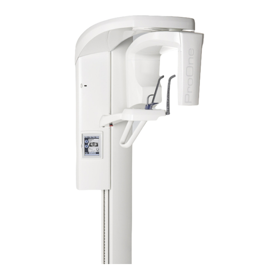
Page 15: General View Of The X-Ray Unit
Temple supports Moving column Patient support Patient support table On/off switch Patient handles Emergency stop button (on the back of the column) Control panel Stationary column Installation Manual Planmeca ProOne 11 Printed copies of this document are considered uncontrolled. 7535.13.Rev001 08.07.2018... -
Page 16: Unpacking The X-Ray Unit
X-ray unit from the C-arm or from the upper arm. NOTE Attach felt pads (included in the delivery) to the underside of the column base plate before you lift up the X-ray unit. Planmeca ProOne Installation Manual Printed copies of this document are considered uncontrolled. - Page 17 UNPACKING THE X-RAY UNIT Lift up the X-ray unit and the support frame (6). Installation Manual Planmeca ProOne 13 Printed copies of this document are considered uncontrolled. 7535.13.Rev001 08.07.2018...
-
Page 18: Installing The X-Ray Unit
Drill two securing holes (ø7 mm (0.3 in.), 70…75 mm (2.75...3 in.) in depth) for the mounting screws. Wall made of concrete or stone NOTE: Extension plate optional Wooden wall ~1700mm (66.9 in.) Planmeca ProOne Installation Manual Printed copies of this document are considered uncontrolled. 7535.13.Rev001 08.07.2018... -
Page 19: Attaching The X-Ray Unit To The Floor
X-ray unit away from the wall so that you can drill the holes. Mark the position of the screws Installation Manual Planmeca ProOne 15 Printed copies of this document are considered uncontrolled. 7535.13.Rev001 08.07.2018... - Page 20 Secure the X-ray unit in position by tightening the four wall bracket attachment screws and the two floor mounting screws to full tightness. NOTE Use a spirit level to ensure that the column is vertical. Planmeca ProOne Installation Manual Printed copies of this document are considered uncontrolled.
- Page 21 Upper arm cover Upper arm frame Connect the X-ray unit to a power supply with a voltage appropriate to the unit you are installing. Installation Manual Planmeca ProOne 17 Printed copies of this document are considered uncontrolled. 7535.13.Rev001 08.07.2018...
-
Page 22: Installing The Exposure Switch
10 “DIAGRAMS” on page 27. CAUTION Only the Planmeca cross connection spiral cable (Planmeca part no. 10001193) can be used between the ProOne X-ray unit and the exposure switch. This cable can be lengthened with an RJ12 Coupler and a Modular extension cable (6wire with 2xRJ12). - Page 23 Ferrite bead Back of moving column Exposure switch cable Screws that hold the protective cover in position Connect the other cable end to the exposure switch. Installation Manual Planmeca ProOne 19 Printed copies of this document are considered uncontrolled. 7535.13.Rev001 08.07.2018...
-
Page 24: Stationary Exposure Switch
The exposure switch can now be positioned on the holder plate. Then attach the exposure switch to the holder plate with an M3x10 DIN 912 screw. Fastening plate Planmeca ProOne Installation Manual Printed copies of this document are considered uncontrolled. - Page 25 Ferrite bead Back of moving column Exposure switch cable Screws that hold the protective cover in position Connect the other cable end to the exposure switch. Installation Manual Planmeca ProOne 21 Printed copies of this document are considered uncontrolled. 7535.13.Rev001 08.07.2018...
-
Page 26: Installing The Digital System
Planmeca Dixi User’s and Installation manual. Connecting the Ethernet cable The ProOne X-ray unit is connected to the local (10/100 Base) network and used from a PC with the Dimaxis/Romexis imaging software. Use an Ethernet cable (UTP cat5e, Planmeca part number 06320060) to connect the ProOne X-ray unit to the network. -
Page 27: Configuring The Ethernet Link
1. The correct Ethernet link cable needs to be attached to the unit (see section 8.1 “Connecting the Ethernet cable” on page 22). 2. The Ethernet settings of the ProOne X-ray unit need to be configured (see below). 3. The used Ethernet link IP Addresses and the configured Net Password must be defined in the DIDAPI configuration (Ethernet Interface settings). -
Page 28: Checking The Ethernet Link Communication
Command Prompt and executing the command “ping <ProOne IP address>”, e.g. ping 192.168.3.220. The ProOne X-ray unit will send a reply message (4 packets) if the Ethernet link is up and running. NOTE If you do not receive a reply message (e.g. Time-out signal) the Ethernet link is not working properly. -
Page 29: Installing The Dimaxis/Romexis Imaging Software
Install the calibration files according to the instructions given in the software installation manual, Appendix DIDAPI CONFIGURATION. NOTE Use only the original calibration file CD-ROM supplied with the Planmeca ProOne X- ray unit - you cannot perform the calibration without the original files. Leave the original CD-ROM at the office where the X-ray unit is installed. -
Page 30: Checking The Alignments
CHECKING THE ALIGNMENTS X-ray beam The beam alignment must be checked after installation. Refer to the ProOne X-ray unit Technical manual, section “Adjusting and calibrating X-ray beam”. Adjust the X-ray beam according to the instructions given in the Technical manual, if necessary. -
Page 31: Diagrams
DIAGRAMS DIAGRAMS Installation Manual Planmeca ProOne 27 Printed copies of this document are considered uncontrolled. 7535.13.Rev001 08.07.2018... - Page 32 Printed copies of this document are considered uncontrolled. 7535.13.Rev001 08.07.2018...
- Page 33 P lanmeca P roOne R emote B utton E U Data wall s ocket connection E xpos ure s witch E xpos ure S piral C able E XP +26V E XP Lamp R eady Lamp P C with grabber card Modular J ack R J -12 Data wall s ocket...
- Page 34 Printed copies of this document are considered uncontrolled. 7535.13.Rev001 08.07.2018...
- Page 35 P lanmeca P roOne R emote B utton US Data wall s ocket connection E xpos ure s witch E xpos ure S piral C able E XP +26V E XP Lamp R eady Lamp P C with grabber card Modular J ack R J -12 Data wall s ocket...
- Page 36 Printed copies of this document are considered uncontrolled. 7535.13.Rev001 08.07.2018...
- Page 37 P lanmeca P roOne Double E xpos ure S witch / R emote connection E U P C with grabber card NOT E ! T he las t F E X s hould be terminate by jumpper J 7 to "ON"-pos ition. E thernet cable UT P cat5e E xpos ure C able 06320060...
- Page 38 Printed copies of this document are considered uncontrolled. 7535.13.Rev001 08.07.2018...
- Page 39 P lanmeca P roOne Double E xpos ure S witch / R emote connection US P C with grabber card NOT E ! T he las t F E X s hould be terminate by jumpper J 7 to "ON"-pos ition. E thernet cable UT P cat5e E xpos ure C able 06320060...
- Page 40 Printed copies of this document are considered uncontrolled. 7535.13.Rev001 08.07.2018...
- Page 41 P lanmeca P roOne E xpos ure S witch / Lamp R emote connection E U P C with grabber card NOT E ! T he las t F E X s hould be terminate by jumpper J 7 to "ON"-pos ition. E thernet cable UT P cat5e 06320060 US B Memory...
- Page 42 Printed copies of this document are considered uncontrolled. 7535.13.Rev001 08.07.2018...
- Page 43 P lanmeca P roOne E xpos ure S witch / Lamp R emote connection US P C with grabber card NOT E ! T he las t F E X s hould be terminate by jumpper J 7 to "ON"-pos ition. E thernet cable UT P cat5e 06320060 US B Memory...
- Page 44 Printed copies of this document are considered uncontrolled. 7535.13.Rev001 08.07.2018...
- Page 45 Printed copies of this document are considered uncontrolled. 7535.13.Rev001 08.07.2018...
- Page 46 Printed copies of this document are considered uncontrolled. 7535.13.Rev001 08.07.2018...
- Page 47 Printed copies of this document are considered uncontrolled. 7535.13.Rev001 08.07.2018...
- Page 48 Planmeca Oy | Asentajankatu 6 | 00880 Helsinki | Finland tel. +358 20 7795 500 | fax +358 20 7795 555 | sales@planmeca.com | www.planmeca.com Printed copies of this document are considered uncontrolled. 7535.13.Rev001 08.07.2018...
Need help?
Do you have a question about the ProOne and is the answer not in the manual?
Questions and answers