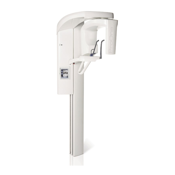
Planmeca ProOne User Manual
Hide thumbs
Also See for ProOne:
- Technical manual (195 pages) ,
- User manual (70 pages) ,
- Manual (57 pages)
Table of Contents
Advertisement
Advertisement
Table of Contents

Related Manuals for Planmeca ProOne


Summary of Contents for Planmeca ProOne
- Page 1 Planmeca ProOne ® user's manual...
-
Page 3: Table Of Contents
Multi-angle TMJ exposure (3 angles lateral) ................ 54 SINUS EXPOSURE ......................59 12.1 Patient positioning ........................ 60 12.2 Taking an exposure ......................62 CROSS-SECTIONAL EXPOSURE (OPTIONAL) ..............64 13.1 Patient positioning ........................ 65 13.2 Taking an exposure ......................69 User’s Manual Planmeca ProOne... - Page 4 IEC 60364 - equipment is used according to the operating instructions. Planmeca pursues a policy of continual product development. Although every effort is made to produce up-to-date product documentation this publication should not be regarded as an infallible guide to current specifications. We reserve the right to make changes without prior notice.
-
Page 5: Introduction
ProOne X-ray unit. Please read these instructions thoroughly before using the unit. You need a PC with the Planmeca Romexis program in order to save, view and modify the images. The Romexis program has a separate manual which should be used in conjunction with this manual. -
Page 6: Symbols On Product Labels
Separate collection for electrical and electronic equipment (Directive 2002/96/EC WEEE) Refer to instruction manual/booklet (Standard ISO 7010-M002) Emergency stop (Standard IEC 60601-1) Warning; Electricity (Standard ISO 7010-W012) General warning sign (Standard ISO 7010-W001) Protective earth (ground) (Standard IEC 60417) Planmeca ProOne User’s Manual... -
Page 7: Symbols On X-Ray Units With Detachable Power Supply Cord
Attention, consult accompanying documents (Standard IEC 60601-1) Separate collection for electrical and electronic equipment (Directive 2002/96/EC WEEE) Warning; Electricity (Standard ISO 7010-W012) Alternating current (Standard IEC 60417) General warning sign (Standard ISO 7010-W001) Protective earth (ground) (Standard IEC 60417) User’s Manual Planmeca ProOne... -
Page 8: Associated Documentation
User’s Manual • Technical Manual The original language of the manuals is English. NOTE The User’s Manuals are available on Planmeca’s website. • For X-ray units, select Material bank > Manuals > Imaging. • For software products, select Material bank >... -
Page 9: Safety Precautions
If the X-ray unit shows any signs of oil leakage, switch the X-ray unit off and contact your service technician for help. CAUTION Do not use the X-ray unit in an oxygen rich environment or in the presence of flammable anesthetics. User’s Manual Planmeca ProOne... - Page 10 EMC requirements have to be considered, and the equipment must be installed and put into service according to the specific EMC information provided in the accompanying documents. NOTE Portable and mobile RF communications equipment can affect the X-ray unit. Planmeca ProOne User’s Manual...
- Page 11 Contact your service technician if you notice a decrease in image quality. NOTE If you take an exposure but the image does not appear in the Planmeca Romexis program, you can import the image manually into Romexis. Refer to the Planmeca Romexis User's Manual for details. NOTE Do not handle liquids near or on the X-ray unit.
-
Page 12: Main Parts
6 MAIN PARTS 6 MAIN PARTS 6.1 General view of X-ray system Ethernet X-ray unit Patient area PC with Planmeca Romexis program (outside patient area) Planmeca ProOne User’s Manual... -
Page 13: General View Of X-Ray Unit
Patient supports (see section 6.4 “Patient supports” on page 11) Patient support table Patient handles Emergency stop button (see section 6.5 “Emergency stop button” on page 11) Control panel (see section 9 “CONTROL PANEL” on page 14) User’s Manual Planmeca ProOne... -
Page 14: Exposure Switch
C-arm will stop moving and a help message will appear on the control panel. The help message must be cleared before the X-ray unit can be used again. Planmeca ProOne User’s Manual... -
Page 15: Patient Supports
X-ray unit are blocked and the unit will not generate radiation. A help message will appear on the control panel display. Release the stop button to resume normal operation. User’s Manual Planmeca ProOne... -
Page 16: Switching X-Ray Unit On
X-ray unit will carry out a self-test which will last a few seconds. The X-ray unit is then ready for use. NOTE To prolong the lifetime of the Planmeca ProOne X-ray unit, always switch the X-ray unit off when it is not in active use. Planmeca ProOne User’s Manual... -
Page 17: Program Packages
8 PROGRAM PACKAGES 8 PROGRAM PACKAGES The Planmeca ProOne X-ray unit offers a wide selection of exposure programs for various diagnostic purposes. The basic program package is included as standard and the other program packages are available as options. Each exposure program has a child setting which reduces the image size and patient dose. -
Page 18: Control Panel
You can choose in which format (e.g. 22.10.2008 for date and 13:49 for time) they will be shown. Refer to section14.1.1 “Setting time and date (U1100)” on page 73 for more information. Planmeca ProOne User’s Manual... -
Page 19: Selecting Panoramic Exposure Program
(U1300)” on page 76 for more information. 9.2 Selecting panoramic exposure program To select a panoramic exposure program, touch the program field on the main display. The main display is the display that is shown when the X-ray unit is switched on. User’s Manual Planmeca ProOne... - Page 20 The Standard panoramic program has a traditional path and angles of the beam. Standard panoramic program Direction of beam Image size for adult setting layer laser beam Image size for child setting 1 cm Planmeca ProOne User’s Manual...
- Page 21 Image size for adult setting layer laser beam 1 cm Image size for child setting NOTE This program is optimized for orthogonal imaging and a shadow of the opposite side teeth may therefore be visible in the radiograph. User’s Manual Planmeca ProOne...
- Page 22 Accept the selection and return to the main display by touching the green check mark button in the bottom right corner of the display. Planmeca ProOne User’s Manual...
- Page 23 The image shown on the display is only an example. The exposed image will not equal the example image. Accept the selections you have made, and return to the main display by touching the green check mark button in the bottom right corner of the display. User’s Manual Planmeca ProOne...
-
Page 24: Selecting Temporomandibular Joint (Tmj) Exposure Program
Select the required TMJ exposure program by touching the appropriate field on the display. The selected program will be highlighted. NOTE The patient positioning lights will be automatically switched on when you select the exposure program. Planmeca ProOne User’s Manual... - Page 25 The imaging angle is adjustable (factory default angle: 17°). 1 cm Double PA: Posteroanterior TMJ exposures of open and closed Double PA temporomandibular joints. The imaging angle is 60° and it is not adjustable. 1 cm User’s Manual Planmeca ProOne...
- Page 26 Second exposure = Angle selected by user (factory default angle: 17°) Third exposure = Selected angle + 7° Accept the selection and return to the main display by touching the green check mark button in the bottom right corner of the display. Planmeca ProOne User’s Manual...
- Page 27 (one line in the middle). NOTE The default imaging angle for lateral exposures (17 degrees) can be changed by the user. Refer to section 14.2.2 “Program presets (P2200)” on page 84 for more information. User’s Manual Planmeca ProOne...
- Page 28 1 2 3 1 cm First exposure = Selected angle - 7° Imaging angle selected by the user Second exposure = Angle selected by the user (factory default angle: 17°) Third exposure = Selected angle + 7° Planmeca ProOne User’s Manual...
-
Page 29: Selecting Sinus Exposure Program
The sinus program “PA rotational” is included in the basic program package. Other sinus programs are optional. NOTE When the child setting (smallest patient size) is selected, the image size and patient dose are automatically reduced. User’s Manual Planmeca ProOne... - Page 30 Lateral non-rotational, right Midsagittal non-rotational The Midsagittal non-rotational program produces lateral (right or left) non-rotational sinus exposures in the middle of the jaw. The exposures can be taken from the left or right jaw side. Planmeca ProOne User’s Manual...
- Page 31 The marking on the patient’s face demonstrates the imaging position. NOTE The imaging position can also be adjusted by touching the target position arrows on the main sinus display for posteroanterior exposures. Target position arrows User’s Manual Planmeca ProOne...
-
Page 32: Selecting Cross-Sectional Exposure Program (Optional)
Select the required cross-sectional exposure program by touching the appropriate field on the display. The selected program will be highlighted. NOTE The patient positioning lights will be automatically switched on when you select the exposure program. Planmeca ProOne User’s Manual... - Page 33 (distance from middle to middle) is adjustable, and it can be 1-10 mm. Accept the selection and return to the main display by touching the green check mark button in the bottom right corner of the display. User’s Manual Planmeca ProOne...
- Page 34 The selected target position will be marked with a red circle. Each preprogrammed target position has a fixed magnification: Tooth No. Magnification (according to Planmeca numbering system) 1.48 1.51 1.56 1.61 1.89 NOTE The tooth numbering system can be changed by the user.
- Page 35 In the automatic program the target position will be Movement automatically moved between exposures. The movement step step is adjustable between 1-10 mm. Select the movement step by touching the plus or minus button next to the step value. User’s Manual Planmeca ProOne...
-
Page 36: Entering Patient Name
To enter a patient name, touch the patient name field. Patient NOTE name We recommend that you always enter the patient name field before you take an exposure. This will ensure that images of different patients cannot be mixed up. Planmeca ProOne User’s Manual... - Page 37 To delete a letter or a number, touch the button. Characters will be deleted one at a time and in reverse Letters/ order of entry. numbers Delete letter/number User’s Manual Planmeca ProOne...
-
Page 38: Selecting Patient Size
Selecting the biggest patient size symbol will automatically change the jaw size setting to “Large”. NOTE Jaw size and shape selection is not possible in sinus programs. NOTE Manual selections (exposure values or jaw size) will override any automatic settings. Planmeca ProOne User’s Manual... -
Page 39: Selecting Kilovolt And Milliampere Values
Selecting kV and mA values manually will override the automatic quick button setting. Quick buttons Accept the selections and return to the main display by touching the green check mark button in the bottom right corner of the display. User’s Manual Planmeca ProOne... -
Page 40: Selecting Jaw Size And Shape
Selecting either of the patient sizes in the middle will automatically change the jaw size setting to “Average”. Selecting the largest patient size will automatically change the jaw size setting to “Large”. field Planmeca ProOne User’s Manual... -
Page 41: Adjusting Unit Height
If something is in danger of becoming trapped, release the button immediately to stop the movement. Clear any obstruction before pressing the button again. CAUTION A safety plate is attached to the column. Keep this area clear at all times. User’s Manual Planmeca ProOne... -
Page 42: Returning C-Arm To Patient Entry Position
C-arm to the patient entry position, if it is not already there. Target position field NOTE Touching either of the target position arrows will switch on the patient positioning lights, if they are not already on. Planmeca ProOne User’s Manual... -
Page 43: Switching Dec On/Off (Optional)
Refer to section 10.2.2 “Taking an exposure with Autofocus (AF)” on page 46 for more information. User’s Manual Planmeca ProOne... -
Page 44: Panoramic Exposure
Place a protective lead apron over the patient’s back if required. Select the panoramic program you require, refer to section 9.2 “Selecting panoramic exposure program” on page 15. Select the patient size as described in section 9.7 “Selecting patient size” on page 34. Planmeca ProOne User’s Manual... -
Page 45: Patient Positioning
You can set the X-ray unit so that the C-arm will automatically return to the patient entry position at the end of an exposure cycle. Refer to section 14.2.3 “Functions after exposure (P2300)” on page 86 for more information. User’s Manual Planmeca ProOne... - Page 46 NOTE If you are using the chin support or chin cup, use for example a cotton roll to ensure that the patient’s upper and lower incisors do not overlap. Planmeca ProOne User’s Manual...
- Page 47 The patient’s back should be straight. If necessary, stretch and straighten the patient’s neck by moving the unit up slightly. Height adjusting buttons Frankfort plane light User’s Manual Planmeca ProOne...
- Page 48 Target pos. patient to open their lips slightly and position the layer light arrows as described above. Check that the Frankfort plane light and the midsagittal plane light are still correctly positioned. Reposition them if necessary. Planmeca ProOne User’s Manual...
-
Page 49: Taking An Exposure
If exposures are taken in rapid succession the X-ray tube will overheat and a cooling time will be shown on the display (e.g. Cooling: 21 s). The cooling time indicates the delay before the next exposure can be taken. User’s Manual Planmeca ProOne... - Page 50 Touch the AF button to switch Autofocus (AF) on. Autofocus adjusts the layer position automatically. The function positions the image layer individually for each patient based on the position and angle of the apices of the upper central incisors. Planmeca ProOne User’s Manual...
- Page 51 Make sure the patient does not move between exposures. Exposure 2 Press the exposure button again to take the second (final image) exposure. The second exposure will produce the actual image and the C-arm will now move through one complete exposure cycle. User’s Manual Planmeca ProOne...
-
Page 52: Temporomandibular Joint Exposure
The preset exposure values are average values and they are only meant to guide the user. If needed, you can change the preset values as described in section 9.8 “Selecting kilovolt and milliampere values” on page 35. Planmeca ProOne User’s Manual... - Page 53 To adjust the height of the unit, press either of the height buttons adjusting buttons on the display until the opening in the chin support is approximately level with the patient’s mouth. The unit moves slowly at first, then faster. User’s Manual Planmeca ProOne...
- Page 54 Frankfort plane light as a reference line, adjust the position of the patient’s head by raising or lowering the unit with the 5° height adjusting buttons. Make sure the patient’s back is straight. Frankfort plane light Planmeca ProOne User’s Manual...
- Page 55 Refer to the Romexis User’s Manual. NOTE Images can be saved on a USB memory stick instead of the computer. Refer to section 14.2.6 “Imaging without PC (P2600)” on page 96 for more information. User’s Manual Planmeca ProOne...
- Page 56 You can move the C-arm to the starting position, if it is not already there, by touching the C-arm return button in the bottom left corner. If necessary, you can stop the exposure procedure by touching the stop button in the bottom right corner. Planmeca ProOne User’s Manual...
- Page 57 When you have taken the exposure the image will be shown on the computer screen. Note that you must accept the image in the Romexis program - only accepted images will be stored in the database. Refer to the Romexis User’s Manual for further information. User’s Manual Planmeca ProOne...
-
Page 58: Multi-Angle Tmj Exposure (3 Angles Lateral)
9.8 “Selecting kilovolt and milliampere values” on page 35. NOTE Always try to minimize the radiation dose to the patient. EXPOSURE VALUES FOR MULTI-ANGLE TMJ PROGRAM PATIENT kV VALUE mA VALUE Child Small adult Average-sized adult Large adult Planmeca ProOne User’s Manual... - Page 59 Patients are not allowed to hang on the patient handles. The pull-down force applied to the patient handles may not exceed 15 kg (33 lb). NOTE We recommend that you image patients with poor health in a sitting position. User’s Manual Planmeca ProOne...
- Page 60 Note that the Frankfort plane light, located on the side of the column, can be moved up or down to accommodate different head sizes. This is done by moving the adjusting lever that is located next to the light slot. Planmeca ProOne User’s Manual...
- Page 61 Second exposure = Angle selected by the user (factory default angle: 17°) Check that the Frankfort plane light and the midsagittal Third exposure = Selected angle + 7° plane light are still correctly positioned. Reposition them if necessary. User’s Manual Planmeca ProOne...
- Page 62 When you have taken the exposure the image will be shown on the computer screen. Note that you must accept the image in the Romexis program - only accepted images will be stored in the database. Refer to the Romexis User’s Manual for further information. Planmeca ProOne User’s Manual...
-
Page 63: Sinus Exposure
9.8 “Selecting kilovolt and milliampere values” on page 35. NOTE Always try to minimize the radiation dose to the patient. EXPOSURE VALUES FOR SINUS PROGRAMS PATIENT kV VALUE mA VALUE Child Small adult Average-sized adult Large adult User’s Manual Planmeca ProOne... -
Page 64: Patient Positioning
Patients are not allowed to hang on the patient handles. The pull-down force applied to the patient handles may not exceed 15 kg (33 lb). NOTE We recommend that you image patients with poor health in a sitting position. Planmeca ProOne User’s Manual... - Page 65 Note that the Frankfort plane light, located on the side of light slot the column, can be moved up or down to accommodate different head sizes. This is done by moving the adjusting lever that is located next to the light slot. User’s Manual Planmeca ProOne...
-
Page 66: Taking An Exposure
(P2600)” on page 96 for more information. The status bar at the bottom of the display will turn green when the unit is ready to take an exposure. Status Green = Ready for exposure Grey = Not ready for exposure Planmeca ProOne User’s Manual... - Page 67 When you have taken the exposure the image will be shown on the computer screen. Note that you must accept the image in the Romexis program - only accepted images will be stored in the database. Refer to the Romexis User’s Manual for further information. User’s Manual Planmeca ProOne...
-
Page 68: Cross-Sectional Exposure (Optional)
9.7 “Selecting patient size” on page Select the image position parameters (jaw half, jaw side, tooth number/TMJ, collimation, and movement step in the automatic program) as described in section 9.5.1 “Selecting imaging position for cross-sectional exposures” on page 30. Planmeca ProOne User’s Manual... -
Page 69: Patient Positioning
(P2300)” on page 86 for more information. Touch the temple support button to open the temple supports if they are not already open. Temple support button Guide the patient to the unit so that they are facing the chin rest. User’s Manual Planmeca ProOne... - Page 70 If you are using the chin support or chin cup, use for example a cotton roll to ensure that the patient’s upper and lower incisors do not overlap. Close the temple supports by touching the temple support button. Temple support button Planmeca ProOne User’s Manual...
- Page 71 The patient’s back should be straight. If necessary, stretch and straighten the patient’s neck by Maxilla.eps moving the unit up slightly. Height adjusting buttons Mandible.eps Target in lower jaw User’s Manual Planmeca ProOne...
- Page 72 The layer light is always positioned on the patient’s left side, even when the target position is on the other jaw side. Check that the midsagittal plane light is still correctly positioned. Reposition it if necessary. Planmeca ProOne User’s Manual...
-
Page 73: Taking An Exposure
Ask the patient to close their lips on the bite piece, swallow, and remain as still as possible. Tell the patient how many exposures you will take so that they do not move before the end of the exposure cycle. Move to a protected area. User’s Manual Planmeca ProOne... - Page 74 If exposures are taken in rapid succession the X-ray tube will overheat and a cooling time will be shown on the display (e.g. Cooling: 21 s). The cooling time indicates the delay before the next exposure can be taken. Planmeca ProOne User’s Manual...
- Page 75 The image will be shown on the computer screen. Note that you must accept the image in the Romexis program - only accepted images will be stored in the database. Refer to the Romexis User’s Manual for further information. User’s Manual Planmeca ProOne...
-
Page 76: Settings
Some of the settings can be used to alter the operation of the X-ray unit. Never use functions that you are not familiar with. The Planmeca ProOne X-ray unit has a number of additional functions for special requirements. The additional functions can be entered by touching the service spanner icon on the main display. -
Page 77: User Settings
Set time and date (U1100) first select the option on the User settings Set time and date (U1100) display. The display will appear. Display time and/or date Select time format Set time Select date format Set date User’s Manual Planmeca ProOne... - Page 78 Accept the new date and time by touching the green check mark button in the bottom right corner of the display. To exit the display without saving the changes, touch the red cross button in the bottom left corner of the display. Planmeca ProOne User’s Manual...
- Page 79 Accept your selection by touching the green check mark button in the bottom right corner of the display. To exit the display without saving the changes, touch the red cross button in the bottom left corner of the display. User’s Manual Planmeca ProOne...
- Page 80 Then use the arrow buttons to adjust the frequency between 500 Hz (low pitch tone) and 2000 Hz (high pitch tone) and test the frequency again. Planmeca ProOne User’s Manual...
- Page 81 To cancel the calibration procedure, touch the red cross button in the bottom left corner of the display. First touch here..and then here User’s Manual Planmeca ProOne...
- Page 82 Accept your selection by touching the green check mark button in the bottom right corner of the display. To exit the display without saving the changes, touch the red cross button in the bottom left corner of the display. Planmeca ProOne User’s Manual...
- Page 83 Network settings (U1400) display. The display will appear. The Planmeca ProOne X-ray unit communicates through an Ethernet link. To enable the communication it is necessary to configure the link settings for the X-ray unit and the PC which is connected to the X-ray unit. This is done by a service technician/local administrator when the digital system is installed.
- Page 84 PCB (printed circuit board) versions have been installed. The information is needed for service and maintenance purposes. Exit the display by touching the green check mark button in the bottom right corner of the display. Planmeca ProOne User’s Manual...
- Page 85 14 SETTINGS 14.1.6 Clinic management (U1600) To view the network settings for the Planmeca Romexis Clinic Clinic Management module, select the option management (U1600) User settings on the display. The Clinic management (U1600) display will appear. NOTE Only a service technician or local administrator may change the settings.
-
Page 86: Program Settings
14.2.1 Program licences (P2100) To activate program features, first select the option Program licences (P2100) Program settings on the Program licences (P2100) display. The display will appear. Planmeca ProOne User’s Manual... - Page 87 NOTE Each licence code is unit and feature specific, i.e. it can only be used on the specified X-ray unit and for the specified program feature. User’s Manual Planmeca ProOne...
- Page 88 View estimated DAP field is highlighted when the function is switched on. To switch off the function, touch View estimated DAP field again. Planmeca ProOne User’s Manual...
- Page 89 Tooth numbering: Touch the arrow buttons to select the tooth numbering system you want to use in cross- sectional programs. The options are: • Planmeca: 0-8, TMJ • ADA: TMJ, 1-4, 13-16, 17-20, 29-32, TMJ • FDI/ISO: TMJ, 18-15, 48-45, 25-28, 35-38, TMJ...
- Page 90 Dragging the zoomed image with your finger will move the image in the desired direction on the display. Touch the green check mark button in the bottom right Preview corner of the display to return to the main display. Planmeca ProOne User’s Manual...
- Page 91 14.2.4 Archive (P2400) Program settings Archive On the display, select the option (P2400) Archive (P2400) . The display will appear. Here you can view the error history and exposure statistics. User’s Manual Planmeca ProOne...
- Page 92 The error history page contains a table listing the error codes reported by the X-ray unit. The table can be arranged by columns in ascending or descending order by clicking the arrow buttons. Planmeca ProOne User’s Manual...
- Page 93 14.2.5 Testing programs (P2500) To perform self diagnostics or to take a beam check or Testing programs QA exposure, first select the option (P2500) Program settings Testing on the display. The programs (P2500) display will appear. User’s Manual Planmeca ProOne...
- Page 94 . The testing program starts and the C- arm, column, temple supports and/or collimator start moving. The test results will be displayed as follows: green check mark = pass, red cross = fail. Functions to be tested selected Test results shown Planmeca ProOne User’s Manual...
- Page 95 X-ray unit. Open the web browser. Enter your X-ray unit’s IP address in the address bar. NOTE Network You can find the IP address on the control panel settings (U1400) >User display Spanner icon >Network settings>IP address). User’s Manual Planmeca ProOne...
- Page 96 14 SETTINGS The main page opens. Click here Beam check Click the link on the ProOne main page. Beam check page opens. Planmeca ProOne User’s Manual...
- Page 97 If any part of the radiation beam extends outside the active sensor area, the X-ray beam must be readjusted and the sensor must be recalibrated by a qualified service technician. Contact your service technician for help. User’s Manual Planmeca ProOne...
- Page 98 The beam check image for child collimation will be shown on the web browser screen. Click here to view image Detailed view of Upper image the top end of the image Lower image Detailed view of the bottom end of the image Planmeca ProOne User’s Manual...
- Page 99 The beam check images can be saved in any folder on the computer or network as a single file web page (.mht file). Beam check (P2520) Exit the display by touching the green check mark button in the bottom right corner. User’s Manual Planmeca ProOne...
- Page 100 If required, you can take a QA exposure to check the image quality of the X-ray unit. Refer to Planmeca Publication Number 10016248 (Image Quality Monitoring Instructions for Planmeca Digital X-ray Units) for a detailed description on how to take a QA exposure.
- Page 101 Dragging the zoomed image with your finger will move the image in the desired direction on the display. Touch the green check mark button in the bottom right Preview Imaging corner of the display to return to the without PC (P2600) display. User’s Manual Planmeca ProOne...
- Page 102 Touch the button to cancel the action, or select to delete the image. NOTE Ensure that you have sent the image to the PC before you delete it. Deleted images cannot be recovered. Planmeca ProOne User’s Manual...
-
Page 103: Help Messages
The exposure button was released before end of exposure. Press and hold down the exposure button for the entire duration of the exposure. H03-014 Control panel Control panel touched The control panel was touched during operation. Operation was interrupted. User’s Manual Planmeca ProOne... - Page 104 H06-001 Emergency stop Button activated The emergency stop button has been button activated. All movements of the X-ray unit are blocked, no radiation is generated. Release the emergency stop button to resume normal operation. Planmeca ProOne User’s Manual...
- Page 105 Target value has to fall between 200 and 2000. H08-001 Software Software downgrade is not allowed. CPU PCB version I2 or newer installed, it is not possible to downgrade the software from version 1.9.1. User’s Manual Planmeca ProOne...
-
Page 106: Error Messages
The X-ray unit will not accept any commands from the user until the error message is cleared from the display. Touch the green check mark button to clear the message. Planmeca ProOne User’s Manual... -
Page 107: Cleaning And Disinfection
NOTE Switch the X-ray unit off before cleaning or disinfection. NOTE Use a Planmeca approved cleaning agent and surface disinfectant. The products are categorised here as cleaning agents and / or disinfectants according to the information provided by the manufacturers. -
Page 108: Patient Supports, Patient Handles And Control Panel
Actichlor Plus SciCan Optim Blue Wipes 17.1 Patient supports, patient handles and control panel Wipe these parts after each patient using a Planmeca approved surface disinfectant. Use a Planmeca approved cleaning agent for cleaning stains and dirt if needed. •... - Page 109 17 CLEANING AND DISINFECTION • Patient handles • Control panel User’s Manual Planmeca ProOne...
-
Page 110: Other Surfaces
17 CLEANING AND DISINFECTION 17.2 Other surfaces Wipe the other surfaces regularly using a Planmeca approved surface disinfectant. Use a Planmeca approved cleaning agent for cleaning stains and dirt if needed. Planmeca ProOne User’s Manual... -
Page 111: Service
100 times. 18 SERVICE The X-ray unit must be checked by a qualified Planmeca service technician once a year or after every 10 000 exposures (if this is sooner). This will guarantee patient and user safety and ensure consistent image quality. -
Page 112: Disposal
19 DISPOSAL 19 DISPOSAL In order to reduce the environmental load over the product’s entire lifecycle, Planmeca’s products are designed to be as safe as possible to manufacture, use and dispose of. Parts which can be recycled should always be taken to the appropriate processing centres, after hazardous waste has been removed. -
Page 113: Technical Specifications
F 8A H 250 V (user replaceable) • 1 fuse on permanently installed X-ray units • 2 fuses on X-ray units with detachable power supply cord External fuse(s) 100 - 240 V ~ / T 10A H 250 V User’s Manual Planmeca ProOne... -
Page 114: Original Manufacturer
Air pressure 800 - 1060 hPa • Max. altitude 2000 m (1.25 miles) RoHS 2011/65/EU IP classification IP20 20.2 Original manufacturer Planmeca Oy, Asentajankatu 6, FIN-00880, Helsinki, Finland Phone: +358 20 7795 500, Fax: +358 20 7795 555, www.planmeca.com Planmeca ProOne User’s Manual... - Page 116 Planmeca Oy | Asentajankatu 6 | 00880 Helsinki | Finland tel. +358 20 7795 500 | fax +358 20 7795 555 | sales@planmeca.com | www.planmeca.com...
Need help?
Do you have a question about the ProOne and is the answer not in the manual?
Questions and answers