Sign In
Upload
Manuals
Brands
Oracle Manuals
Tablet
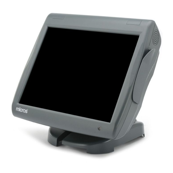
MICROS Workstation 5A
Oracle MICROS Workstation 5A Terminal Manuals
Manuals and User Guides for Oracle MICROS Workstation 5A Terminal. We have
2
Oracle MICROS Workstation 5A Terminal manuals available for free PDF download: Setup Manual, Site Preparation Manual
Oracle MICROS Workstation 5A Setup Manual (183 pages)
Brand:
Oracle
| Category:
Touch terminals
| Size: 6 MB
Table of Contents
Table of Contents
4
Preface
13
Why Read this Manual
13
Purpose
13
How this Manual Is Organized
14
Notation Conventions
15
Symbols
15
In this Chapter
16
Chapter 1 - What Is the Workstation 5A?
17
The System
17
Workstation 5A
17
Casework
18
Compact Flash (CF) Riser Card
18
DMA (Direct Memory Access) CF Cards
18
Finger Print Reader
18
Internal Speakers
18
Magnetic Card Reader
18
Operator LCD Panel and Touchscreen
18
Operator LED
18
Operator Power Button
18
Recovery Button
19
Hard Disk
20
Mini-PCI Options
20
Workstation 5A Options
20
Powered USB
21
Finger Print Reader
22
Workstation Mounting Options
23
The Workstation 5A Adjustable Stand
23
Power Supply Compartment
24
LCD Customer Display Options
25
Integrated LCD Customer Display
25
LCD Pole Mount Customer Display
26
Protégé Customer Display System
27
Software Components
28
Firmbase
28
Operating Systems
28
Workstation 5A
28
Workstation 5A Platform Software
29
Utilities
29
POS Application
29
Recovery
30
One Button Recovery
30
Windows CE
30
Windows Posready 2009
30
Power Management States
31
Unplugged
31
Nopower
31
Last Power State Retention
31
Specifications
33
General Specifications
33
Approvals
35
Chapter 2 - Workstation 5A BIOS
37
The BIOS Configuration Utility
37
The BIOS System Configuration Utility
37
Wifi
37
System Summary BIOS Q1000G
38
System Summary BIOS Q1010M
38
System Summary BIOS Q2010G
39
System Summary BIOS Q2011D
39
BIOS Q2010G Features
40
BIOS Q2011D Features
40
BIOS Versions Q2010G/Q2011D Known Issues
40
Tips for Using the System Configuration Utility
41
Main
42
Phoenix System BIOS
42
Processor (CPU)
42
System Memory (RAM)
42
Real Time Clock (RTC)
42
Exit
43
Save, Restore and Exit Setup
43
Exit Setup Without Saving Changes
43
Save Settings and Restart
43
Reload SATA WIN32 Factory Default Settings (Q2010G/Q2011D)
44
Reload USB WIN32 Factory Default Settings (Q2010G/Q2011D)
44
Reload Win32 Factory CMOS Defaults (Q1000G/Q1010M)
44
Reload WINCE Factory CMOS Defaults (Q1000G/Q1010M)
44
Reload WINCE Factory Default Settings (Q2010G/Q2011D)
44
Boot
45
System Boot Configuration
45
Boot Device Prioritization - BIOS Boot Specification (BBS)
45
Windows CE Boot Configuration (All BIOS Versions)
45
Reload SATA WIN32 Factory Default Settings (Q2010G/2011D)
46
Reload USB WIN32 Factory Default Settings (Q2010G/Q2011D)
46
Windows Posready Boot Configuration
46
IDE Drive Configuration
46
Intel ich 8M ATA Controller Configuration
46
Post
47
Pnp
48
Sio
49
Features
50
Firmbase
51
Misc
52
Video
53
Odm
54
Special Configuration
55
Boot Test Image (All BIOS Versions)
55
Cash Drawer Voltage (All BIOS Versions)
55
Personality Module (All BIOS Versions)
55
SATA WIN32 Factory Restore (Q2010G and Q2011D)
56
USB WIN32 Factory Restore (Q2010G and Q2011D)
56
WINCE Factory Restore (All BIOS Versions)
56
WINCE Image Update (All BIOS Versions)
56
Compact Flash (Q2011D)
57
Enable Password for Restore (Q2010G and Q2011D)
57
Chipset
58
Advancedcpu
59
Upgrading the WS5A BIOS
60
Windows Embedded CE 6.0
60
Posready 2009
61
Windows CE Factory Restore
62
Chapter 3 - What's Inside?
65
Disassembling the Workstation 5A
65
System Board Components
70
WS5A System Board - Primary Components
70
WS5A System Board - Connectors
71
WS5A System Board - Jumpers and Switches
72
WS5A System Board Connectors (Revision F)
73
System Board Jumper Configuration
74
J12 - Touch Screen Select
74
J20 - CMOS Reset
74
J5 - TFT Panel Mode
74
System Board Block Diagrams
75
Workstation 5A Block Diagram
75
System Block Diagrams
75
System Board Description
77
Intel Atom N450 General Features
77
Graphics Processing Unit (GPU)
78
Integrated Memory Controller (ICM)
78
Direct Media Interface
79
ICH8M General Features
79
USB 2.0 Ports
80
Ide
81
PCI Express
81
Ethernet
82
HD Audio
82
PCI Bus
82
Spi
82
Gpio
83
Lpc
83
Smbus
83
Lcd/Touchscreen Assembly - Resistive Touchscreen
84
CCFL Backlight Inverter Board
85
Lcd/Touchscreen Assembly - Optional Capacitive Touchscreen
86
Installing Options
87
USB Hard Drive
88
Ddr2 So-DIMM
89
Installation and Removal
90
DMA Enabled CF Riser Card
91
USB Wireless Module
92
Mini-PCI Options
92
Workstation 5A Hard Disk Kit
93
LCD Customer Display - Integrated
94
Pole LCD Customer Display
96
Protégé Customer Display System - Integrated
97
Protégé Customer Display System - Pole Mount
98
Reassembling the WS5A
100
Chapter 4 - Installing and Operating the Workstation 5A
105
Care and Handling
105
Equipment Placement
105
Location
105
Proximity to Foreign Materials
105
Noise Induction
105
Electrostatic Discharge
106
AC Power and Data Cabling Requirements
106
Lcd/Touchscreen
106
Cabinet
106
Magnetic Card Reader
106
Magnetic Stripe Reader
106
The IO Panel
107
Idn
108
Com5
108
Rear Display
108
Ant
108
12V/+24V Select - USB6
109
Vga
109
Opt
109
Com1
109
Com2
109
Usb1 - Usb4
110
10/100/1000 Ethernet
110
Cf/Express Card
110
DMA Enabled CF Card
110
CF Card Cover Slot
111
How to Use the Compact Flash (CF) Card
111
Disabling the CF Card
112
Removing a CF Card
112
Installing the CF Card
113
Customer Display
113
Cash Drawer #1 - Cash Drawer #2
113
+12V out
113
Installation
114
Operation
117
Operator Features
117
Turning the Workstation from NOPOWER to on
118
Booting to Windows Embedded CE 6.0 R3
119
Booting to Posready 2009
120
Turning the Workstation from on to NOPOWER
120
Using the Search Feature
121
CAL Keyboard Hot Keys
122
Configuring a Static IP Address
122
Main Screen Saver
123
Backlight Control
124
Controlling the IO Panel USB Ports (Windows CE or Posready)
125
Using the Windows CE Input Panel
125
Using the Posready 2009 On-Screen Keyboards
125
Using the Magnetic Strip Card
127
Tips for Using Magnetic Cards
127
Calibrating the Touchscreen
128
When to Calibrate the Touchscreen
128
Workstation 5A Recovery
129
Recovery Button
129
ODM Tab
129
BIOS - Password and Login Requirements
129
BIOS Q1000G
130
WINCE Factory Restore - Recovery Button at Splash Screen
130
BIOS Q1010M (Login and Password Required)
131
BIOS Q2010G and Q2011D
131
BIOS Q1000G
132
Posready Recovery CF - Recovery Button at Splash Screen
132
BIOS Q2010G/Q2011D (Password Required)
133
Win32 Factory Restore
134
WINCE Factory Restore
134
Pre-Boot Menu (BIOS Q1010M Only)
135
WINCE Factory Restore
135
ODM Tab (BIOS Q2010G and Q2011D)
136
USB WIN32 Factory Restore
136
WINCE Factory Restore
136
SATA WIN32 Factory Restore
137
WINCE Factory Restore from the on State
138
WINCE Factory Restore from the Soft-Off (S5) State
138
Starting the Posready Recovery CF from the on State
139
Starting the Posready Recovery CF from the Soft-Off State
139
Disabling the Recovery Password in BIOS Q2010G/Q2011D
140
Error: 'Image File Not Found' or Using a Custom Recovery Image
140
Error: 'Recovery Detected 2 USB Hard Drives Installed
141
Chapter 5 - Workstation 5A Diagnostics
143
Basic Troubleshooting
143
Workstation 5A Diagnostics
145
Running the WS5A Windows CE Diagnostics Utility
145
System Information Screen
145
Activity Counters, Dump Sys Info and Recovery Image Info
148
Testing Cash Drawers
150
Controlling the IO Panel USB Ports
151
Running the WS5A Diagnostics Utility (Posready 2009)
153
Wipe Compact Flash (WCF) Utility - WINCE Only
154
Appendix A: Equipment Dimensions
157
In this Appendix
157
Workstation 5A Low Profile
157
Workstation 5A Low Profile /W Protégé Customer Display
158
WS5A on Adjustable Stand with Rear LCD Customer Display
159
Workstation 5A on Adjustable Stand /W 6" LCD Pole Display
160
Workstation 5A on Adjustable Stand /W Protégé Customer Display
161
Workstation 5A on Adjustable Stand and Protégé on 6" Pole
162
LCD Pole Display
163
Protégé Customer Display on 6" Pole
164
Cash Drawers
165
Appendix B: Connector and Cable Diagrams
166
IO Panel Connectors
167
IDN Port
167
RS232 Connector
169
Cash Drawer 1 and 2 Connectors
169
Remote Customer Display Connector
170
System Board Connectors
171
Magnetic Stripe Interface
171
Hook-Up Cables
172
LCD Customer Display Cables
173
Remote Pole LCD Customer Display
174
Ethernet
175
Cash Drawer Extension Cable
177
Appendix C: FCC/DOC Statement
178
Appendix D: Oracle Linux for MICROS General Information
180
Advertisement
Oracle MICROS Workstation 5A Site Preparation Manual (181 pages)
Brand:
Oracle
| Category:
Tablet
| Size: 22 MB
Table of Contents
Table of Contents
3
Introduction to the Oracle MICROS Hardware
12
MICROS Compact Workstation 310
13
MICROS Compact Workstation 310 Technical Specifications
14
MICROS Compact Workstation 310 Features
15
MICROS Compact Workstation 310 Primary I/O Ports
16
MICROS Flexible Stand
16
MICROS Basic Stand
17
MICROS Compact Workstation 310 Accessories
19
The Oracle MICROS Tablet 700 Series
20
MICROS Tablet 700 Series Technical Specifications
20
MICROS Tablet 720 Features
22
MICROS Tablet 721 Features
24
MICROS Tablet Accessories
25
Replacing the Bridge Battery in the MICROS Tablet 720
28
MICROS Workstation 6 Series
31
MICROS Workstation 6 Features and Specifications
31
MICROS Workstation 6 Series Primary I/O Ports
34
MICROS Workstation 6 Series Internal I/O Ports
35
MICROS Workstation 6 Series Adjustable Stand
35
MICROS Tablet E-Series 8 and E-Series
37
MICROS Tablet E-Series with MSR Sleeve Features
38
MICROS Tablet E-Series 8 with MSR Sleeve Connectors
39
MICROS Tablet R-Series
43
MICROS Tablet R-Series Features MICROS Tablet R-Series Connectors
43
MICROS Tablet R-Series Features
43
MICROS Base Station
46
MICROS Base Station Features MICROS Base Station Connectors
47
MICROS Base Station Features
47
MICROS Tablet Multi-Unit Charger
49
MICROS Tablet Multi-Unit Charger Features
49
MICROS PC Workstation 2015
51
MICROS PC Workstation 2015 Features
51
MICROS PC Workstation 2015 Connectors
52
MICROS PC Workstation 2010
53
MICROS PC Workstation 2010 Features MICROS PC Workstation 2010 Connectors
53
MICROS PC Workstation 2010 Features
53
MICROS Workstation 5A
55
MICROS Workstation 5A Features MICROS Workstation 5A Connectors
55
MICROS Workstation 5A Features
55
MICROS Workstation 5
57
MICROS Workstation 5 Features MICROS Workstation 5 Connectors
57
MICROS Workstation 5 Features
57
MICROS Workstation 4 LX
59
MICROS Workstation 4 LX Features
59
MICROS Workstation 4 LX Connectors
60
MICROS Keyboard Workstation 270
61
MICROS Keyboard Workstation 270 Features MICROS Keyboard Workstation 270 Connectors
61
MICROS Keyboard Workstation 270 Features
61
Order Confirmation System
63
Order Confirmation Controller (OCC) Features
64
Remote Display Unit Features and Requirements
64
Order Confirmation System Installation
65
Order Confirmation Controller (OCC) Requirements
65
Remote Display Pedestal Requirements
65
E7 BOC or Digital Menu and Marketing System Controller
68
E7 BOC Features and Requirements
68
Printing Devices
70
Ethernet RS232
70
MICROS Integrated Device Network (IDN)
70
Peripheral Devices
71
10-Inch Customer Display
71
Customer Display
71
Cash Drawer
72
Barcode Reader
72
Coin Changer
72
Magnetic Card Reader
73
Scale
73
Order Confirmation and Payment Terminal
73
Kitchen Display System (KDS)
74
Kitchen Display System Installation
75
KDS Mounting
75
KDS Controllers
75
MICROS Wired Bumpbar Installation Considerations MICROS Wireless Bumpbar Installation Considerations
75
E7 Kitchen Video Monitor Controller
77
E7 KVM Controller Features and Requirements
78
E7 Kitchen Video Monitor (KVM) Installation
79
Environmental Requirements and Equipment Placement Considerations
81
Location
81
Foreign Materials
81
Noise Induction
82
Electrostatic Discharge
82
Humidity
82
Custom Cabinets and Enclosures
82
Temperature
82
Lithium Ion Battery Pack Storage Considerations
83
AC Power Requirements
85
Preferred AC Power System
85
AC Power System Grounding
87
MICROS Power Panel Grounding
87
MICROS Branch Circuit Grounding
87
AC Power Receptacles Grounding
88
Additional Methods for AC Power
88
Relaxed/Power Conditioned AC Power System
88
Power Conditioned AC Power System
89
AC Power Consumption and Volt-Amp Ratings for MICROS Equipment
90
Recommended AC Power Conditioning and UPS Equipment
93
UPS Product Requirements
93
Powervar Single Phase UPS Desktop Models
93
ONEAC Rack Mount UPS
93
Standard Power Conditioners
95
POWERVAR Ground Guard Line Conditioners
96
Ethernet Line Protectors
97
Powervar Single Phase Desktop UPS - Estimated Run Times
97
Network Requirements and Planning
102
Structured Cabling Systems
102
Elements of a Structured Cabling System
104
Structured Cabling Examples
105
Cable Types
108
Cable Categories
108
Mechanical and Electrical Considerations for Cable Installation
109
Ethernet Network Installation
111
Topology
111
Topology Cable Runs
111
Workstations, IP Printers, KDS Controller, and OCC LAN Cable Termination
111
Extending Ethernet Beyond the 90 Meter Limit with Fiber Optic Cable
113
Integrated Device Network (IDN) Installation
115
Recommended Cables for a MICROS RS422 ION Network
115
Traditional MICROS RS422 Cabling and Connection Hardware
116
Wall Plate
116
6-Pin Modular Connector
116
Patch Cables
116
IDN Connectors on MICROS Workstations Cable Runs
116
Shielded Cable and Connection Hardware for IDN
117
Components
117
IDN Connectors
118
Terminating the IDN Cable
119
Equipment Dimensions
121
MICROS Compact Workstation 310 with Flexible Stand - Dimensions
123
MICROS Compact Workstation 310 with Basic Stand - Dimensions
123
MICROS Tablet 721 - Front and Side Dimensions
124
MICROS Tablet 720 - Front and Side Dimensions
124
MICROS Tablet 700 Series - 4-Bay Tablet Charger Dimensions
126
MICROS Tablet 700 Series - 4-Bay Battery Charger Dimensions
127
MICROS Workstation 6 Series - Front and Back Dimensions with Adjustable Stand
128
MICROS Workstation 6 Series - Side Dimensions with Adjustable Stand
129
MICROS Workstation 6 Series - Side Dimensions with Adjustable Stand and High-Mount Customer Display
130
MICROS Workstation 6 Series - Side Dimensions with 10-Inch Customer Display and High Mount
131
MICROS Workstation 6 Series - 10-Inch Customer Display with Pole Mount Dimensions
132
MICROS Workstation 6 Series - Wall Mount Dimensions
133
MICROS Tablet E-Series 8 Dimension
135
MICROS Tablet E-Series 11 Dimensions
135
MICROS Tablet E-Series Multi-Unit Charger - Surface Mount Dimensions
136
MICROS Tablet E-Series Multi-Unit Charger - Wall Mount Dimensions
137
MICROS Tablet R-Series Dimensions
138
MICROS Tablet R-Series - Base Station Dimensions with Peripherals
139
MICROS PC Workstation 2015 - Low Profile Dimensions
140
MICROS PC Workstation 2015 - Low Profile with Customer Facing Display Dimensions
141
MICROS PC Workstation 2015 Adjustable Stand Dimensions
142
MICROS PC Workstation 2015 on Stand - LCD Customer Display Dimensions
143
MICROS PC Workstation 2015 - Adjustable Stand Protégé Customer Display Dimensions
144
MICROS Workstation 5/5A - Low Profile Dimensions
145
MICROS Workstation 5/5A Dimensions with Integrated LCD Customer Display
146
MICROS Workstation 5/5A Dimensions on Adjustable Stand
147
MICROS Workstation 5/5A Dimensions on Stand with LCD Customer Display
148
MICROS Workstation 5/5A Dimensions on Stand with Protégé Customer Display
149
MICROS Workstation 5/5A Dimensions on Stand /W Vivo Payment Terminal
150
MICROS Workstation 4/4 LX - Low Profile (LP) Dimensions
151
MICROS Workstation 4/4 LX - Low Profile with Rear Customer Display Dimensions
152
MICROS Workstation 4/4 LX Dimensions on Adjustable Stand
153
MICROS Workstation 4/4 LX Dimensions on Stand with LCD Customer Display
154
MICROS Workstation 4/4 LX Dimensions on Stand with VFD Customer Display
155
MICROS Workstation 4/4 LX Dimensions on Wall Mount Bracket
156
MICROS KW270 Low Profile Dimensions
157
MICROS KW270 on Stand with Updated Scanner Housing Dimensions
158
Order Confirmation Controller and Wall Bracket Dimensions
159
Order Confirmation System Remote Display Pedestal - Basic Dimensions
160
Order Confirmation System Remote Display Pedestal - Detail 1 Dimensions
161
Order Confirmation System Remote Display Pedestal - Detail 2 Dimensions
162
Order Confirmation System Remote Display Pedestal Baseplate Dimensions
163
MICROS 10-Key Bumpbar Mounting Bracket Dimensions
164
MICROS 20-Key Bumpbar Mounting Bracket Dimensions
164
TM-T88 Thermal Roll Printer Dimensions
165
U200D Roll Printer Dimensions
165
U220 Auto-Cut Roll Printer Dimensions
166
U200B Auto-Cut Roll Printer Dimensions
166
U230 Auto-Cut Roll Printer Dimensions
167
Pole Mount (6 Inch) Protégé Customer Display Dimensions
168
Series 1 Pole Customer Display Dimensions
169
Series 2 Pole Customer Display Dimensions
170
Cash Drawer Dimensions
171
Connectors
172
RS422-A, RS422-B or IDN
172
Modular RS232 COM or Powered RJ45 Port Diagram
174
RS232 DB9 Connector
174
Cash Drawer 1 and 2 Connectors
175
Pole Customer Display Connector
176
Hook-Up Cables
177
Null Modem Cable for E7 KVM Controller
177
IDN Port Conversion Cables
177
8-Pin to 6-Pin Hook-Up RS422 Cable
179
IDN to EIA/TIA-568-A Patch Cable
180
FCC/DOC Statement
181
Federal Communications Commission Radio Frequency Interference Statement
181
Canadian Department of Communications Statement
181
Advertisement
Related Products
Oracle MICROS Workstation 5
Oracle MICROS Workstation 6 Series
Oracle MICROS Workstation 4 LX
Oracle MICROS PC Workstation 2015
Oracle MICROS PC Workstation 2010
Oracle MICROS Keyboard Workstation 270
Oracle 5.0
Oracle Tekelec 5100
Oracle MICROS Workstation 8
oracle e-series
Oracle Categories
Server
Storage
Network Hardware
Software
Controller
More Oracle Manuals
Login
Sign In
OR
Sign in with Facebook
Sign in with Google
Upload manual
Upload from disk
Upload from URL