
Subscribe to Our Youtube Channel
Related Manuals for Omron NX-ID


Summary of Contents for Omron NX-ID
- Page 1 Machine Automation Controller NX-series Digital I/O Units User’s Manual NX-ID NX-IA NX-OC NX-OD NX-MD Digital I/O Units W521-E1-07...
- Page 2 No patent liability is assumed with respect to the use of the information contained herein. Moreover, because OMRON is constantly striving to improve its high-quality products, the information contained in this manual is subject to change without notice. Every precaution has been taken in the preparation of this manual. Neverthe- less, OMRON assumes no responsibility for errors or omissions.
-
Page 3: Introduction
For programming, this manual is intended for personnel who understand the programming language specifications in international standard IEC 61131-3 or Japanese standard JIS B 3503. Applicable Products This manual covers the following product. • NX-series Digital I/O Unit NX-ID /IA /OD/OC/MD NX-series Digital I/O Unit User’s Manual (W521) -
Page 4: Table Of Contents
CONTENTS CONTENTS Introduction ......................1 Intended Audience............................1 Applicable Products ............................. 1 Relevant Manuals ..................... 7 Manual Structure ...................... 8 Page Structure and Icons ..........................8 Special Information ............................9 Precaution on Terminology ........................10 Terms and Conditions Agreement ................ 11 Warranty, Limitations of Liability ........................ - Page 5 CONTENTS Model List..........................1-7 1-3-1 Model Notation..........................1-7 1-3-2 Digital Input Units........................1-10 1-3-3 Digital Output Units........................1-12 1-3-4 Digital Mixed I/O Units ......................1-15 List of Functions........................1-16 1-4-1 Digital Input Units........................1-16 1-4-2 Digital Output Units........................1-17 1-4-3 Digital Mixed I/O Units ......................
- Page 6 CONTENTS 5-2-2 Setting the I/O Refreshing Methods .................... 5-7 5-2-3 Selecting NX Units ........................5-8 5-2-4 Free-Run Refreshing........................5-8 5-2-5 Synchronous Input Refreshing....................5-12 5-2-6 Synchronous Output Refreshing ....................5-16 5-2-7 Time Stamp Refreshing......................5-19 5-2-8 Input Refreshing with Input Changed Time................5-20 5-2-9 Output Refreshing with Specified Time Stamp................
- Page 7 CONTENTS 9-3-1 Checking for Errors from the Sysmac Studio................9-5 9-3-2 Checking for Errors from Support Software Other Than the Sysmac Studio......9-6 9-3-3 Event Codes and Corrections for Errors..................9-7 9-3-4 Meaning of Error ........................9-10 Resetting Errors ........................9-19 Troubles Specific To Each Type of NX Units..............
- Page 8 CONTENTS Index NX-series Digital I/O Unit User’s Manual (W521)
-
Page 9: Relevant Manuals
Relevant Manuals Relevant Manuals The table below provides the relevant manuals for the NX-series Digital I/O Units. Read all of the manuals that are relevant to your system configuration and application to make the most of the NX-series Digital I/O Units. Other manuals, such as related product manuals, are necessary for specific system configurations and applications. -
Page 10: Manual Structure
Manual Structure Manual Structure Page Structure and Icons The following page structure and icons are used in this manual. Level 1 heading 4 Installation and Wiring Level 2 heading Level 3 heading Mounting Units Level 2 heading Gives the current Level 3 heading headings. -
Page 11: Special Information
Manual Structure Special Information Special information in this manual is classified as follows: Precautions for Safe Use Precautions on what to do and what not to do to ensure safe usage of the product. Precautions for Correct Use Precautions on what to do and what not to do to ensure proper operation and performance. Additional Information Additional information to read as required. -
Page 12: Precaution On Terminology
Manual Structure Precaution on Terminology • In this manual, “download” refers to transferring data from the Support Software to a physical device and “upload” refers to transferring data from a physical device to the Support Software. • In this manual, the directions in relation to the Units are given in the following figure, which shows upright installation. -
Page 13: Terms And Conditions Agreement
Omron’s exclusive warranty is that the Products will be free from defects in materials and workman- ship for a period of twelve months from the date of sale by Omron (or such other period expressed in writing by Omron). Omron disclaims all other warranties, express or implied. -
Page 14: Application Considerations
Disclaimers Performance Data Data presented in Omron Company websites, catalogs and other materials is provided as a guide for the user in determining suitability and does not constitute a warranty. It may represent the result of Omron’s test conditions, and the user must correlate it to actual application requirements. Actual perfor- mance is subject to the Omron’s Warranty and Limitations of Liability. -
Page 15: Safety Precautions
Safety Precautions Safety Precautions Definition of Precautionary Information The following notation is used in this manual to provide precautions required to ensure safe usage of an NX-series Digital I/O Unit. The safety precautions that are provided are extremely important to safety. Always read and heed the information provided in all safety precautions. -
Page 16: Warnings
Safety Precautions Warnings WARNING During Power Supply Do not touch the terminal section while power is ON. Electric shock may occur. Do not attempt to take any Unit apart. In particular, high-voltage parts are present in Units that supply power while power is sup- plied or immediately after power is turned OFF. -
Page 17: Cautions
Safety Precautions Voltage and Current Inputs Make sure that the voltages and currents that are input to the Units and slaves are within the specified ranges. Inputting voltages or currents that are outside of the specified ranges may cause accidents or fire. - Page 18 Safety Precautions Online Editing Execute online editing only after confirming that no adverse effects will be caused by devia- tions in the timing of I/O. If you perform online editing, the task execution time may exceed the task period, I/O may not be refreshed with external devices, input signals may not be read, and output timing may change.
-
Page 19: Precautions For Safe Use
Precautions for Safe Use Precautions for Safe Use Transporting • When transporting any Unit, use the special packing box for it. Also, do not subject the Unit to excessive vibration or shock during transportation. • Do not drop any Unit or subject it to abnormal vibration or shock. Doing so may result in Unit malfunction or burning. - Page 20 Precautions for Safe Use • Do not write on an NX Unit with ink within the restricted region that is shown in the following figure. Also do not get this area dirty. When the Unit is installed or removed, ink or dirt may adhere to the pins in the NX bus connector, which may result in malfunctions in the CPU Rack or the Slave Termi- nal.
- Page 21 Precautions for Safe Use Wiring • Double-check all switches and other settings and double-check all wiring to make sure that they are correct before turning ON the power supply. • Use the correct wiring parts and tools when you wire the system. •...
- Page 22 Precautions for Safe Use Turning ON the Power Supply • When you set the Operating Mode at Startup, confirm that no adverse effect will occur in the system. Actual Operation • Before you start operation, always register the NX Units that are connected to the Communications Coupler Unit in the host communications master as the Unit Configuration Information.
- Page 23 Precautions for Safe Use Unit Replacement • When you replace a Unit, start operation only after you transfer the settings and variables that are required for operation to the new Unit. Disposal • Dispose of the product according to local ordinances as they apply. NX-series Digital I/O Unit User’s Manual (W521)
-
Page 24: Precautions For Correct Use
Precautions for Correct Use Precautions for Correct Use Storage, Mounting, and Wiring • Follow the instructions in this manual to correctly perform installation and wiring. • Do not operate or store the Units in the following locations. Doing so may result in malfunction, in operation stopping, or in burning. -
Page 25: Regulations And Standards
Concepts EMC Directives OMRON devices that comply with EU Directives also conform to the related EMC standards so that they can be more easily built into other devices or the overall machine. The actual products have been checked for conformity to EMC standards.*1 Whether the products conform to the standards in the system used by the customer, however, must be checked by the customer. -
Page 26: Conformance To Ul And Csa Standards
NX-series product must also comply with the standards, consult with your OMRON representative. Application conditions are defined according to the installation location. Application may not be possible for some installation locations. -
Page 27: Unit Versions
Unit Versions Unit Versions This section describes the notation that is used for unit versions, the confirmation method for unit ver- sions, and the relationship between unit versions and Support Software versions. Unit Versions A “unit version” has been introduced to manage the Units in the NX Series according to differences in functionality accompanying Unit upgrades. -
Page 28: Unit Versions And Support Software Versions
Gives the lot number and unit version of the Unit. unit version • DDMYY: Lot number, : Used by OMRON. “M” gives the month (1 to 9: January to September, X: October, Y: November, Z: December) • 1: Unit version The decimal portion of the unit version is omitted. -
Page 29: Related Manuals
The following table shows related manuals. Use these manuals for reference. Manual name Cat. No. Model numbers Application Description NX-series Digital I/O W521 NX-ID Learning how to The hardware, setup methods, and Units User’s Manual use NX-series Dig- functions of the NX-series Digital I/O NX-IA ital I/O Units Units are described. - Page 30 Related Manuals Manual name Cat. No. Model numbers Application Description NX-series Ether- W536 NX-EIC202 Learning how to The following items are described: the use an NX-series overall system and configuration meth- Net/IP Coupler Unit EtherNet/IP Cou- ods of an EtherNet/IP Slave Terminal User’s Manual pler Unit and Eth- (which consists of an NX-series Ether-...
- Page 31 Related Manuals Manual name Cat. No. Model numbers Application Description NY-series IPC Machine W556 NY512- Learning the basic An introduction to the entire NY-series system is provided along with the fol- Controller Industrial Box specifications of PC Hardware User's the NY-series lowing information on the Industrial Box Manual Industrial Box PCs,...
-
Page 32: Terminology
Terminology Terminology Abbre- Term Description viation application layer status, AL status Status for indicating information on errors that occur in an application on a slave. CAN application protocol over Ether- A CAN application protocol service implemented on EtherCAT. CAN in Automation CiA is the international users' and manufacturers' group that develops and supports higher-layer protocols. - Page 33 Terminology Abbre- Term Description viation Operational A state in EtherCAT communications where SDO communications and I/O are possible. PDO communications An acronym for process data communications. Pre-Operational A state in EtherCAT communications where only SDO communications are possible with the slaves, i.e., no I/O can be performed. primary periodic task The task with the highest priority.
-
Page 34: Revision History
Revision History Revision History A manual revision code appears as a suffix to the catalog number on the front and back covers of the manual. Cat. No. W521-E1-07 Revision code Revision code Date Revised content April 2013 Original production June 2013 Added time stamp refreshing, models on time stamp refreshing and cor- rected mistakes. -
Page 35: Sections In This Manual
Sections in this Manual Sections in this Manual Features and System Inspection and Configuration Maintenance Appendices Specifications Part Names and Index Functions Installation and Wiring I/O Refreshing Digital Input Units Digital Output Units Digital Mixed I/O Units Troubleshooting NX-series Digital I/O Unit User’s Manual (W521) - Page 36 Sections in this Manual NX-series Digital I/O Unit User’s Manual (W521)
-
Page 37: Features And System Configuration
Features and System Configura- tion This section describes NX system configuration and the types of Digital I/O Units. 1-1 Features and Types of Digital I/O Units ......1-2 1-1-1 Digital I/O Unit Features . -
Page 38: Features And Types Of Digital I/O Units
1 Features and System Configuration Features and Types of Digital I/O Units This section describes features and types of Digital I/O Units. 1-1-1 Digital I/O Unit Features The Digital I/O Units are NX Units to process inputs and outputs of digital signals (ON/OFF signals). The NX-series Digital I/O Units have the following features. -
Page 39: Digital I/O Unit Types
1 Features and System Configuration Controlling Outputs at Fixed Intervals After Inputs Change You can use NX-series CPU Units or EtherCAT Coupler Units with NX Units that support input refresh- ing with input changed time and with other NX Units that support output refreshing with specified time stamp to control the outputs at fixed intervals after the sensor inputs change. -
Page 40: System Configuration
1 Features and System Configuration System Configuration NX Unit NX-series Digital I/O Units can be connected to the following Units. • NX-series CPU Unit • NX-series Communications Coupler Unit The following explains the system configuration for each NX Unit connection destination. 1-2-1 System Configuration in the Case of a CPU Unit The following figure shows a system configuration when a group of NX Units is connected to an... -
Page 41: System Configuration Of Slave Terminals
1 Features and System Configuration Sym- Item Description End Cover The End Cover is attached to the end of a CPU Rack. Support Software A computer software application for setting, programming, debugging, and troubleshooting NJ/NX/NY-series Controllers. (Sysmac Studio) For an NX1P2 CPU Unit, this application performs setting operation by making a connection to a built-in EtherNet/IP port. - Page 42 82 Position Control Units even though they can operate as EtherCAT masters. *2. The term Support Software indicates software that is provided by OMRON. If you connect to a master from another company, use the software tool corresponding to that master.
-
Page 43: Model List
1 Features and System Configuration Model List 1-3-1 Model Notation The Digital I/O Unit models are assigned based on the following rules. NX - - Unit type ID : DC input IA : AC input OD : Transistor output OC : Relay output MD : DC input/Transistor output Number of points 2 : 2 points... -
Page 44: Digital Input Units
1 Features and System Configuration Other Specifications Digital Input Units ON/OFF response I/O refreshing method time Free-Run refreshing only Input voltage Exceeds Input refreshing with input 1 μs max. Switching Synchronous I/O 1 μs changed time only refreshing and Free-Run refreshing 12 to 24 VDC or 240 VAC... - Page 45 1 Features and System Configuration Digital Mixed I/O Units Input section Output section Other func- ON/OFF response time tions Rated Rated input Load I/O refreshing volt- Load voltage current method Exceeds 1 μs max. short-circuit 1 μs protection 12 to Switching Synchro- nous I/O refresh- 24 VDC...
-
Page 46: Digital Input Units
1 Features and System Configuration 1-3-2 Digital Input Units This section shows the specifications for Digital Input Units. Refer to A-1-2 Digital Input Units on page A-7 for details on the specifications of individual Digital Input Units. DC Input Units (Screwless Clamping Terminal Block, 12 mm Width) Internal I/O Rated input I/O refreshing... - Page 47 1 Features and System Configuration DC Input Units (MIL Connector, 30 mm Width) Internal I/O Rated input I/O refreshing ON/OFF response Model Reference common voltage method time poin For both NX-ID5142-5 point 24 VDC P. A-28 Switching Synchro- NPN/PNP nous I/O refreshing 20 μs max./400 μs and Free-Run max.
-
Page 48: Digital Output Units
1 Features and System Configuration 1-3-3 Digital Output Units This section shows the specifications for Digital Output Units. Refer to A-1-3 Digital Output Units on page A-38 for details on the specifications of individual Digital Output Units. Transistor Output Units (Screwless Clamping Terminal Block, 12 mm Width) Maximum Num-... - Page 49 1 Features and System Configuration Transistor Output Units (M3 Screw Terminal Block, 30 mm Width) Maximum Num- ON/OFF Internal I/O value of Rated volt- I/O refresh- Refer- Model ber of response common load cur- ing method ence points time rent Switching 0.1 ms 12 to 24...
- Page 50 1 Features and System Configuration Relay Output Units (Screwless Clamping Terminal Block, 12 mm Width) Num- ON/OFF Maximum switching I/O refresh- Refer- Model ber of Relay type response capacity ing method ence points time NX-OC2633 N.O. 250 VAC/2 A (cosΦ = 1), P.
-
Page 51: Digital Mixed I/O Units
1 Features and System Configuration 1-3-4 Digital Mixed I/O Units This section shows the specifications for Digital Mixed I/O Units. Refer to A-1-4 Digital Mixed I/O Units on page A-82 for details on the specifications of individual Mixed I/O Units. DC Input/Transistor Output Units (MIL Connector, 30 mm Width) Maximum Num-... -
Page 52: List Of Functions
1 Features and System Configuration List of Functions This section provides an overview of functions that the Digital I/O Units have. Refer to the specifications of each model in A-1 Data Sheet on page A-2 for details on the functions. 1-4-1 Digital Input Units Function name... -
Page 53: Digital Output Units
1 Features and System Configuration 1-4-2 Digital Output Units Function name Description Reference Free-Run Refreshing With this I/O refreshing method, the refresh cycle of the NX 5-2-4 Free-Run Refreshing on bus and the I/O refresh cycles of the NX Units are asynchro- page 5-8 nous. -
Page 54: Digital Mixed I/O Units
1 Features and System Configuration 1-4-3 Digital Mixed I/O Units Function name Description Reference Free-Run Refreshing With this I/O refreshing method, the refresh cycle of the NX 5-2-4 Free-Run Refreshing on bus and the I/O refresh cycles of the NX Units are asynchro- page 5-8 nous. -
Page 55: Support Software
1 Features and System Configuration Support Software The Support Software that is used depends on the system configuration. Support Software for a System Configured with a CPU Unit If your system is configured by connecting an NX Unit to a CPU Unit, the Sysmac Studio is used as the Support Software. - Page 56 1 Features and System Configuration 1 - 20 NX-series Digital I/O Unit User’s Manual (W521)
-
Page 57: Specifications
Specifications This section describes the general specifications and individual specifications of Digital I/O Units. 2-1 General Specifications ......... 2-2 2-2 Individual Specifications . -
Page 58: General Specifications
*2. Varies with NX Unit Models. Refer to A-1 Data Sheet on page A-2 for the specifications of individual NX Units. *3. Refer to the OMRON website (www.ia.omron.com) or ask your OMRON representative for the most recent ap- plicable standards for each model. -
Page 59: Individual Specifications
2 Specifications Individual Specifications Refer to A-1 Data Sheet on page A-2 for the specifications of individual Digital I/O Units. 2 - 3 NX-series Digital I/O Unit User’s Manual (W521) - Page 60 2 Specifications 2 - 4 NX-series Digital I/O Unit User’s Manual (W521)
-
Page 61: Part Names And Functions
Part Names and Functions This section describes the names and functions of the Digital I/O Unit parts. 3-1 Part Names ........... 3-2 3-1-1 Screwless Clamping Terminal Block Type . -
Page 62: Part Names
NX Units (12 mm Width) Let- Name Function Marker attachment loca- The locations where markers are attached. The markers made by OMRON tions are installed for the factory setting. Commercially available markers can also be installed. Refer to 4-1-2 Attaching Markers on page 4-4 NX bus connector This connector is used to connect each Unit. - Page 63 NX Units (24 mm Width) Let- Name Function Marker attachment loca- The locations where markers are attached. The markers made by OMRON tions are installed for the factory setting. Commercially available markers can also be installed. Refer to 4-1-2 Attaching Markers on page 4-4 NX bus connector This connector is used to connect each Unit.
- Page 64 3 Part Names and Functions Terminal Blocks There are two models of screwless clamping terminal blocks: NX-TB2 and NX-TB1. Each model has three types of terminal blocks: 8-terminal type, 12-terminal type, and 16-terminal type. NX-TB2 16-terminal type 8-terminal type 12-terminal type 24 mm Width 8-terminal type ×2 NX-TB1...
- Page 65 3 Part Names and Functions Let- Name Function Terminal number indi- Terminal numbers for which A and B indicate the column, and 1 to 8 indicate cations the line are displayed. The terminal number is a combination of column and line, i.e. A1 to A8 and B1 to B8.
- Page 66 3 Part Names and Functions Applicable Terminal Blocks for Each Unit Model The following indicates the terminal blocks that are applicable to each Unit. Terminal block Unit model number Number of Ground terminal Model Current capacity terminals mark NX-ID3 NX-TBA121 Not provided NX-TBA122 10 A...
-
Page 67: M3 Screw Terminal Block Type
NX Units (30 mm Width) Let- Name Function Marker attachment loca- The locations where markers are attached. The markers made by OMRON tions are installed for the factory setting. Commercially available markers can also be installed. Refer to 4-1-2 Attaching Markers on page 4-4 NX bus connector This connector is used to connect each Unit. -
Page 68: Connector Types
Units with MIL Connectors (1 Connector with 20 Terminals) Let- Name Function Marker attachment loca- The locations where markers are attached. The markers made by OMRON tion are installed for the factory setting. Commercially available markers can also be installed. Refer to 4-1-2 Attaching Markers on page 4-4. - Page 69 Units with MIL Connectors (1 Connector with 40 Terminals) Let- Name Function Marker attachment loca- The locations where markers are attached. The markers made by OMRON tion are installed for the factory setting. Commercially available markers can also be installed. Refer to 4-1-2 Attaching Markers on page 4-4.
- Page 70 Units with MIL Connectors (2 Connectors with 20 Terminals) Let- Name Function Marker attachment loca- The locations where markers are attached. The markers made by OMRON tion are installed for the factory setting. Commercially available markers can also be installed. Refer to 4-1-2 Attaching Markers on page 4-4.
- Page 71 Units with Fujitsu Connectors (1 Connector with 40 Terminals) Let- Name Function Marker attachment loca- The locations where markers are attached. The markers made by OMRON tion are installed for the factory setting. Commercially available markers can also be installed. Refer to 4-1-2 Attaching Markers on page 4-4.
- Page 72 Units with Fujitsu Connectors (2 Connectors with 24 Terminals) Let- Name Function Marker attachment loca- The locations where markers are attached. The markers made by OMRON tion are installed for the factory setting. Commercially available markers can also be installed. Refer to 4-1-2 Attaching Markers on page 4-4.
-
Page 73: Indicators
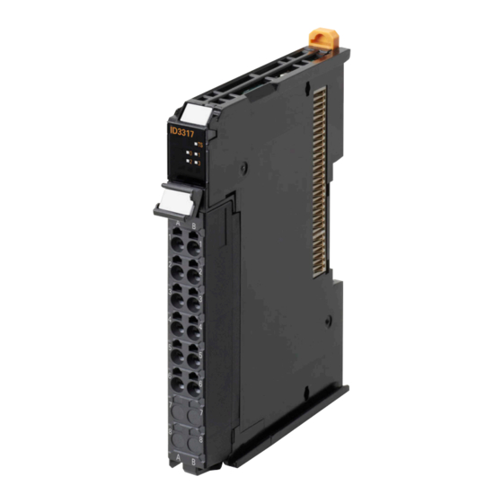
3 Part Names and Functions Indicators There are the indicators to show the current operating status of the Unit or the signal I/O status on the Digital I/O Units. The following indicator patterns are available depending on width of the Unit and the number of I/O points. - Page 74 3 Part Names and Functions NX Units (30 mm Width) 16-point type 32-point type 16-point + 16-point type (Mixed I/O Units) Let- Name Function Model number indications The model numbers of the NX Unit are displayed. (Example) "ID3317" in the case of NX-ID3317 The NX Units are separated in the following color depending on the type of inputs and outputs.
-
Page 75: Ts Indicator
3 Part Names and Functions 3-2-1 TS Indicator This indicator shows the current status of the Digital I/O Unit and its communications status with the CPU Unit or with the Communications Coupler Unit. The meanings of light statuses are described as follows: Color Status Description... -
Page 76: In/Out Indicator
3 Part Names and Functions 3-2-2 IN/OUT Indicator This indicator shows the signal I/O status of each terminal of the Digital I/O Units. For Digital Mixed I/O Units, the indicator shows as follows. OUT indicator IN indicator Color Status Description Yellow Digital I/O is ON Not lit... -
Page 77: Installation And Wiring
Installation and Wiring This section describes how to install the NX Units, the types of power supplies provided to the NX Units and wiring methods, and how to wire the NX Units. 4-1 Installing NX Units ..........4-2 4-1-1 Installing NX Units . -
Page 78: Installing Nx Units
4 Installation and Wiring Installing NX Units This section describes how to install NX Units. Refer to the user's manual for the CPU Unit or Communications Coupler Unit to which NX Units are connected for information on preparations of installation and installation in a control panel. 4-1-1 Installing NX Units This section describes how to mount two NX Units to each other. - Page 79 4 Installation and Wiring Precautions for Correct Use • When you install an NX Unit, do not touch or bump the pins in the NX bus connector. • When you handle an NX Unit, be careful not to apply any stress to the pins in the NX bus connector.
-
Page 80: Attaching Markers
Attaching Markers You can attach markers to the NX Units to identify them. The plastic markers made by OMRON are installed for the factory setting. The ID information can be written on them. Commercially available markers can also be installed. - Page 81 Manufactured by Weidmuller Markers UC1-TMF8 DEK 5/8 Special marker printer UM EN BLUEMARK X1 PrintJet PRO The markers made by OMRON cannot be printed on with commercially available special printers. 4 - 5 NX-series Digital I/O Unit User’s Manual (W521)
-
Page 82: Removing Nx Units
4 Installation and Wiring 4-1-3 Removing NX Units Precautions for Safe Use Always turn OFF the Unit power supply and I/O power supply before you remove the NX Unit. Use a flat-blade screwdriver to pull up the DIN Track mounting hook on the Unit to remove. Flat-blade screwdriver DIN track mounting hook Put your fingers on the protrusions for removing multiple NX Units including the Unit to be... -
Page 83: Installation Orientation
4 Installation and Wiring Precautions for Correct Use • When removing an NX Unit, remove multiple Units together which include the one you want to remove. If you attempt to remove only one Unit, it is stuck and hard to pull out. •... - Page 84 4 Installation and Wiring Installation Orientation in the Case of a Slave Terminal Orientation is possible in the following six directions. (A) is the upright orientation and (B) to (F) are other orientations. Upper Lower However, there are restrictions on the installation orientation and restrictions to specifications that can result from the Communications Coupler Units and NX Units that are used.
-
Page 85: Power Supply Types And Wiring
4 Installation and Wiring Power Supply Types and Wiring There are the following two types of power supplies that supply power to the NX Units. Power supply name Description NX Unit power supply This power supply is used for operating the NX Units. I/O power supply This power supply is used for driving the I/O circuits of the NX Units and for the con- nected external devices. - Page 86 Refer to the NX-series System Unit User’s Manual (Cat. No. W523) for the specifications of these Units. For a complete list of the latest power supply Units in the NX Series, refer to the product catalog or OMRON websites, or contact your OMRON representatives. 4 - 10 NX-series Digital I/O Unit User’s Manual (W521)
-
Page 87: Calculating The Total Current Consumption From I/O Power Supply
4 Installation and Wiring 4-2-2 Calculating the Total Current Consumption from I/O Power Sup- The total current consumption of I/O power supplied from the NX bus must be within the range of the maximum I/O power supply current of the Communications Coupler Unit or the Additional I/O Power Supply Unit. -
Page 88: Wiring The Terminals
4 Installation and Wiring Wiring the Terminals This section describes how to wire the terminals on the Digital I/O Units. WARNING Make sure that the voltages and currents that are input to the Units and slaves are within the speci- fied ranges. - Page 89 4 Installation and Wiring Applicable Wires The wires that you can connect to the screwless clamping terminal block are twisted wires, solid wires, and ferrules that are attached to the twisted wires. The following section describes the dimensions and processed methods for applicable wires. Dimensions of Wires Connected to the Terminal Block The dimensions of wires that you can connect into the terminal holes of the screwless clamping ter- minal block are as in the figure below.
- Page 90 4 Installation and Wiring Using Ferrules If you use ferrules, attach the twisted wires to them. Observe the application instructions for your ferrules for the wire stripping length when attaching fer- rules. Always use plated one-pin ferrules. Do not use unplated ferrules or two-pin ferrules. The applicable ferrules, wires, and crimping tools are listed in the following table.
- Page 91 4 Installation and Wiring Using Twisted Wires/Solid Wires If you use twisted wires or solid wires, use the following table to determine the correct wire specifica- tions. Terminals Wire type Conductor Classifica- Current Twisted wires Solid wire Wire size length (strip- ping length) tion capacity...
- Page 92 4 Installation and Wiring Connecting/Removing Wires This section describes how to connect and remove wires. Terminal Block Parts and Names Release hole Terminal hole Required Tools Use a flat-blade screwdriver to connect and remove wires. Use the following flat-blade screwdriver. Side view Front view 8 to 12°...
- Page 93 4 Installation and Wiring Connecting Ferrules Insert the ferrule straight into the terminal hole. It is not necessary to press a flat-blade screwdriver into the release hole. Ferrule After you make a connection, make sure that the ferrule is securely connected to the terminal block. Connecting Twisted Wires/Solid Wires Use the following procedure to connect the twisted wires or solid wires to the terminal block.
- Page 94 4 Installation and Wiring Leave the flat-blade screwdriver pressed into the release hole and insert the twisted wire or the solid wire into the terminal hole. Insert the twisted wire or the solid wire until the stripped portion is no longer visible to prevent shorting.
- Page 95 4 Installation and Wiring Precautions for Safe Use • Do not press the flat-blade screwdriver straight into the release hole. Doing so may break the terminal block. • When you insert a flat-blade screwdriver into a release hole, press it down with a force of 30 N max.
- Page 96 4 Installation and Wiring Securing Wires It is necessary to secure wires to the screwless clamping terminal block depending on the wire types that are used or the current flows on the wires. The following table gives the necessity for securing wires. Wire type Terminals Twisted wires...
- Page 97 4 Installation and Wiring Bundle the wires with a cable tie and secure them to the screwless clamping terminal block. Secure wires within the range of 30 mm from the screwless clamping terminal block. 30 mm 4 - 21 NX-series Digital I/O Unit User’s Manual (W521)
- Page 98 4 Installation and Wiring Removing Wires Use the following procedure to remove the wires from the terminal block. The removal method is the same for ferrules, twisted wires, and solid wires. If wires are secured firmly to the terminal block, release them first. Press the flat-blade screwdriver diagonally into the release hole.
- Page 99 4 Installation and Wiring Precautions for Safe Use • Do not press the flat-blade screwdriver straight into the release hole. Doing so may break the terminal block. • When you insert a flat-blade screwdriver into a release hole, press it down with a force of 30 N max.
- Page 100 4 Installation and Wiring Removing a Terminal Block Press the lock lever on the terminal block and pull out the top of the terminal block to remove it. Lock lever Terminal block 4 - 24 NX-series Digital I/O Unit User’s Manual (W521)
- Page 101 4 Installation and Wiring Attaching a Terminal Block Mount the terminal block hook on the guide at the bottom of the NX Unit, lift up the terminal block, and press in on the top of the terminal block until you hear it engage. The terminal block will click into place on the Unit.
- Page 102 4 Installation and Wiring Preventing Incorrect Attachment of Terminal Blocks In order to prevent unintentionally installing the wrong terminal block, you can limit the combination of a Unit and a terminal block. Insert three Coding Pins (NX-AUX02) into three of the six incorrect attachment prevention holes on the Unit and on the terminal block.
- Page 103 4 Installation and Wiring Types of Coding Pins There are two types of Coding Pins, both with their own unique shape: one for terminal blocks and one for Units. Three pins come with each runner. For terminal block For Unit Runners Coding Pins (Use this part.) Use the following Coding Pins.
- Page 104 1 through 6 in the figure below. As shown in the following table, there are 20 unique pin patterns that can be used. Terminal block Unit Holes used by Holes used by OMRON OMRON Holes for incorrect Holes for incorrect attachment prevention attachment prevention...
- Page 105 Precautions for Correct Use • OMRON uses the holes other than No. 1 to 6 in the figure on the previous page. If you insert a Coding Pin into one of the holes used by OMRON on the terminal block side, this makes it impossible to mount the terminal block on a Unit.
- Page 106 4 Installation and Wiring Unit 4 - 30 NX-series Digital I/O Unit User’s Manual (W521)
-
Page 107: Wiring To M3 Screw Terminal Block
4 Installation and Wiring 4-3-2 Wiring to M3 Screw Terminal Block This section describes how to connect wires to the M3 screw terminal block, and the installation and removing methods. Wiring Terminals The terminals to be wired are as follows. •... - Page 108 4 Installation and Wiring Connecting/Removing Wires • Make sure that all Units are connected properly. • Do not allow wire clippings, shavings, or other foreign material to enter any Unit during wiring. • Wire the Units so that they can be easily replaced. •...
- Page 109 4 Installation and Wiring Removing a Terminal Block Release the lock of the terminal block. (1) Pull the terminal block cover forward to open the cover. (2) Pull the terminal block lever downward. Support the NX Unit firmly while performing the operation of the terminal block lever. Terminal block cover Terminal block lever Pull out the terminal block straight forward to remove.
- Page 110 4 Installation and Wiring Attaching a Terminal Block Insert the terminal block straight into the NX Unit all the way. Lock the terminal block. (1) Push in the terminal block lever upward. (2) Close the terminal block cover if it is still open. Terminal block lever Terminal block cover 4 - 34...
-
Page 111: Wiring To Mil/Fujitsu Connectors
Depending on the connector, the following methods are used to connect the Digital I/O Units with con- nectors to external I/O devices. • Use an OMRON Connecting Cable (equipped with a special connector) to connect to a terminal block or relay terminal. - Page 112 Transistor Output Unit, 32 points NX-OD6256-5 NX-MD6121-5 DC Input/Transistor Output Units, 16 inputs, 16 20 (× 2) outputs NX-MD6256-5 Applicable Cable-side Connectors Connection Pins OMRON set DDK parts Pressure-welded XG4M-4030-T FRC5-A040-3TOS XG4M-2030-T FRC5-A020-3TOS Crimped XG5N-401 XG5N-201 NX Units with Fujitsu Connectors...
- Page 113 4 Installation and Wiring Wire Size We recommend using cable with wire gauges of AWG 24 or AWG 28 (0.2 mm to 0.08 mm ). Use cable with external wire diameters of 1.61 mm max. Wiring NX Units with MIL Connectors •...
- Page 114 4 Installation and Wiring Assemble the connector (purchased separately). Small screws (3) Connector cover Small screws (2) Socket Connector lock screws Cable bracket Nuts (3) Nuts (2) Mount the connector on the Digital I/O Unit and fix it in place with lock screws. Tighten the connector lock screws to a torque of 0.2 •...
-
Page 115: Checking The Wiring
4 Installation and Wiring 4-3-4 Checking the Wiring Check the wiring by reading input data or writing output data from Slave Terminals using the Watch Tab Page of the Support Software. For Input Units, you can turn ON/OFF the inputs from external devices that are connected to the target Units and monitor the results. -
Page 116: Wiring Examples
4 Installation and Wiring Wiring Examples This section gives some wiring examples for the Digital I/O Units and precautions for wiring. 4-4-1 Wiring the Input Units Wiring to the DC Input Units (When I/O Power Is Supplied from the NX Bus) NPN Type Input Units This is the wiring for contact output type external devices. - Page 117 4 Installation and Wiring This is the wiring for three-wire sensors. Communications Coupler Unit or Additional I/O Power Supply Unit Three-wire sensor Output DC Input Unit PNP Type Input Units This is the wiring for contact output type external devices. Communications Coupler Unit or Additional I/O Power Supply Unit Contact output...
- Page 118 4 Installation and Wiring This is the wiring for two-wire sensors. Communications Coupler Unit or Additional I/O Power Supply Unit Two-wire sensor DC Input Unit This is the wiring for three-wire sensors. Communications Coupler Unit or Additional I/O Power Supply Unit Three-wire sensor DC Input Unit Output...
- Page 119 4 Installation and Wiring Precautions when Connecting a Two-wire DC Sensor When a two-wire sensor is used with a DC Input Unit, check that the following conditions are met. Failure to meet these conditions may result in operating errors. (a) Relation between ON voltage of the DC Input Unit and sensor residual voltage The DC Input Unit cannot detect sensor output ON unless the following conditions are satisfied: ≤...
- Page 120 4 Installation and Wiring (b) Relation between input current to the DC Input Unit and sensor control output (load current) The DC Input Unit cannot detect sensor output ON unless the following conditions are satisfied: (min) ≤ I ≤ I (max) (min): Minimum value of load current (max): Maximum value of load current...
- Page 121 4 Installation and Wiring The voltages and currents related to the conditions for NPN type sensors are shown in the figure below. Communications Coupler Unit or Additional I/O Power Supply Unit Two-wire sensor DC Input Unit The voltages and currents related to the conditions for PNP type sensors are shown in the figure below.
- Page 122 4 Installation and Wiring (c) Relation between OFF current of the DC Input Unit and sensor leakage current The DC Input Unit cannot detect sensor output OFF unless the following conditions are satisfied: ≥ I leak When I is greater than I , connect a bleeder resistor R.
- Page 123 A programming example is shown below. The sensor's power supply voltage is used as the input bit to Sensor_power. A 100-ms timer delay (the time required for an OMRON Proximity Sensor to stabilize) is created in the user program. After the timer changes to TRUE, input bit X causes the output Output to change to TRUE after the input of the sensor changes to TRUE.
- Page 124 4 Installation and Wiring Wiring to the DC Input Units (When I/O Power Is Supplied from an External Source) Use the following information for reference when selecting or connecting input devices. DC Input Units The following types of DC input devices can be connected. Contact output Two-wire DC output DC Input Unit...
- Page 125 4 Installation and Wiring Precautions when Connecting a Two-wire DC Sensor When a two-wire sensor is used with a DC Input Unit, check that the following conditions are met. Failure to meet these conditions may result in operating errors. (a) Relation between ON voltage of the DC Input Unit and sensor residual voltage ≤...
- Page 126 A programming example is shown below. The sensor's power supply voltage is used as the input bit to Sensor_power. A 100-ms timer delay (the time required for an OMRON Proximity Sensor to stabilize) is created in the user program. After the timer changes to TRUE, input bit X causes the output Output to change to TRUE after the input of the sensor changes to TRUE.
- Page 127 4 Installation and Wiring Wiring to the AC Input Units Contact Output AC Input Unit AC Switching Proximity AC Input Unit switch main circuit Precautions for Safe Use If you use reed switches for the input contacts for AC Input Units, use switches with an allow- able current of 1 A or greater.
-
Page 128: Precautions When Wiring To The Output Units
4 Installation and Wiring 4-4-2 Precautions when Wiring to the Output Units Output Short-circuit Protection If a load connected to the output terminals is short-circuited, output components and printed circuit boards may be damaged. To guard against this, use the NX Units with load short-circuit protection. When using the NX Units without load short-circuit protection, incorporate a protective fuse in the exter- nal circuit. - Page 129 4 Installation and Wiring Countermeasure 2 Mount a limiting resistor. When I/O power is supplied from the NX bus, the method is as shown in the following figure. NPN type PNP type Communications Communications Coupler Unit or Coupler Unit or Additional I/O Power Additional I/O Power Supply Unit...
- Page 130 4 Installation and Wiring 4 - 54 NX-series Digital I/O Unit User’s Manual (W521)
-
Page 131: I/O Refreshing
I/O Refreshing This section describes the types and functions of I/O refreshing for the NX Units. 5-1 I/O Refreshing ..........5-2 5-1-1 I/O Refreshing from CPU Units to NX Units . -
Page 132: I/O Refreshing From Cpu Units To Nx Units
5 I/O Refreshing I/O Refreshing This section describes I/O refreshing for NX Unit. 5-1-1 I/O Refreshing from CPU Units to NX Units An NX-series NX1P2 CPU Unit cyclically performs I/O refreshing with the NX Units. The following period and two cycles affect operation of the I/O refreshing between the CPU Unit and the NX Units. -
Page 133: I/O Refreshing From Cpu Units Or Industrial Pcs To Slave Terminal
5 I/O Refreshing 5-1-2 I/O Refreshing from CPU Units or Industrial PCs to Slave Terminal The CPU Unit or Industrial PC cyclically performs I/O refreshing with the Slave Terminal through the Communications Master and Communications Coupler Units. The following four cycles affect operation of the I/O refreshing between the NX Unit on a Slave Terminal and the CPU Unit or Industrial PC. - Page 134 5 I/O Refreshing Operation of I/O Refreshing with NX-series CPU Units The following shows the operation of I/O refreshing when the built-in EtherCAT port on the NX-series CPU Unit is used for communications with an EtherCAT Slave Terminal. • The process data communications cycle in item (b) and the refresh cycle of the NX bus in item (c) are automatically synchronized with the primary period or the task period of the priority-5 periodic task of the CPU Unit in item (a).
-
Page 135: I/O Refreshing Methods
5 I/O Refreshing I/O Refreshing Methods This section describes I/O refreshing methods for the NX Units. 5-2-1 Types of I/O Refreshing Methods Methods of I/O Refreshing between the CPU Unit and NX Units The I/O refreshing methods that you can use between the CPU Unit and the NX Units depend on the connected CPU Unit. - Page 136 5 I/O Refreshing Methods of I/O Refreshing between the Communications Coupler Unit and NX Units The I/O refreshing methods that you can use between the Communications Coupler Unit and the NX Units depend on the Communications Coupler Unit that is used. Refer to the user’s manual for the connected Communications Coupler Unit for information on the I/O refreshing methods that you can use between the Communications Coupler Unit and the NX Units.
-
Page 137: Setting The I/O Refreshing Methods
5 I/O Refreshing 5-2-2 Setting the I/O Refreshing Methods Setting Methods between the CPU Unit and the NX Units How to set an I/O refreshing method between the CPU Unit and the NX Units is determined by the con- nected CPU Unit. Refer to the software user’s manual for the connected CPU Unit for information on how to set an I/O refreshing method between the CPU Unit and the NX Units. -
Page 138: Selecting Nx Units
5 I/O Refreshing *1. Two types of time stamp refreshing are available: one is input refreshing with input changed time and the other is output refreshing with specified time stamp. *2. The EtherCAT Slave Terminal operates in DC Mode. *3. The EtherCAT Slave Terminal operates in Free-Run Mode. *4. - Page 139 5 I/O Refreshing Inputs (a) I/O refreshing for NX Units (d) Interval of the timing to read inputs is not constant. I/O refreshing of the NX bus Input refreshing Output refreshing ON/OFF response time Timing to read inputs Digital Input Unit A ON/OFF response time Input filter time Digital Input Unit B...
- Page 140 5 I/O Refreshing Slave Terminal Operation The following describes the operation of Free-Run refreshing for Slave Terminals. • The Communications Coupler Unit performs I/O refreshing for NX Units. (Refer to (a) in the figure below.) • The NX Units read inputs or refresh outputs at the time of I/O refreshing. (Refer to (b) in the figure below.) •...
- Page 141 5 I/O Refreshing Inputs (a) I/O refreshing for NX Units (d) Interval of the timing to read inputs is not constant. I/O refreshing of the NX bus Input refreshing Output refreshing ON/OFF response time Timing to read inputs Digital Input Unit A ON/OFF response time Input filter time Digital Input Unit B...
-
Page 142: Synchronous Input Refreshing
5 I/O Refreshing Settings Add NX Units that support Free-Run refreshing to the CPU Unit configuration or Slave Terminal configuration. After you add the NX Units, set an I/O refreshing method depending on the connected CPU Unit or Communications Coupler Unit so that these NX Units operate with Free-Run refreshing. Refer to 5-2-2 Setting the I/O Refreshing Methods on page 5-7 for information on how to set an I/O refreshing method. - Page 143 5 I/O Refreshing I/O refreshing synchronization (c) Interval of I/O refreshing The longest AD conversion time is not constant. is within one cycle. (d) Interval of synchronization timing is constant. (b) The CPU Unit reads the data that is read by the Unit at I/O refreshing. Offset between Not constant.
- Page 144 5 I/O Refreshing Slave Terminal Operation The following describes the operation of synchronous input refreshing of an EtherCAT Slave Termi- nal connected to the built-in EtherCAT port. • All Digital Input Units and Analog Input Units that operate with synchronous input refreshing in the Slave Terminal read their inputs at the same time at a fixed interval bases on Sync0.
- Page 145 5 I/O Refreshing I/O refreshing synchronization (c) Interval of I/O refreshing The longest AD conversion time is not constant. is within one cycle. (b) The Communications Coupler Unit (d) Interval of Sync0 is constant. reads the data that is read by the Unit Offset between at I/O refreshing.
-
Page 146: Synchronous Output Refreshing
5 I/O Refreshing Settings Add NX Units that support synchronous I/O refreshing to the CPU Unit configuration or Slave Terminal configuration. After you add the NX Units, set an I/O refreshing method depending on the connected CPU Unit or Communications Coupler Unit so that these NX Units operate with synchronous I/O refreshing. Refer to 5-2-2 Setting the I/O Refreshing Methods on page 5-7 for information on how to set an I/O refreshing method. - Page 147 5 I/O Refreshing Offset between synchronization timing and timing to refresh outputs This time is automatically calculated by the Sysmac Studio. (b) The CPU Unit refreshes the output I/O refreshing synchronization values at I/O refreshing. The longest DA conversion time (c) Interval of I/O refreshing (d) Interval of synchronization timing is within one cycle.
- Page 148 5 I/O Refreshing Offset between Sync0 and timing to refresh outputs This time is automatically calculated by the Sysmac Studio. (b) The Communication Coupler Unit refreshes I/O refreshing synchronization the output values at I/O refreshing. The longest DA conversion time (c) Interval of I/O refreshing (d) Interval of Sync0 is constant.
-
Page 149: Time Stamp Refreshing
5 I/O Refreshing 5-2-7 Time Stamp Refreshing With this I/O refreshing method, the NX Units record the DC times when inputs change or perform out- puts at specified DC times. These times are not synchronized to the NX bus refresh cycles. Among Slave Terminals, only EtherCAT Slave Terminals support this refreshing method. -
Page 150: Input Refreshing With Input Changed Time
5 I/O Refreshing 5-2-8 Input Refreshing with Input Changed Time With this I/O refreshing method, the Input Units record the DC times when the inputs changed. The DC times are not synchronized to the NX bus refresh cycles. Among Slave Terminals, only EtherCAT Slave Terminals support this refreshing method. - Page 151 5 I/O Refreshing (b) The CPU Unit reads the input changed (d) Interval of I/O refreshing synchronization (c) Interval of I/O refreshing times that are read by the Unit and the is not constant. synchronization The longest AD conversion time input values at this point at I/O timing is constant.
- Page 152 5 I/O Refreshing • You can select to either detect changes at the input rising edge, or at the input falling edge. Make the setting in advance. Synchronization timing Synchronization timing Synchronization timing I/O refreshing Input refreshing of the NX bus Output refreshing DC time The trigger setting is...
- Page 153 5 I/O Refreshing Slave Terminal Operation The following describes the operation of input refreshing with input changed time of an EtherCAT Slave Terminal connected to the built-in EtherCAT port. • The NX Units that support input refreshing with input changed time record the DC times when an input changes for each input bit.
- Page 154 5 I/O Refreshing I/O refreshing synchronization (b) The Communications Coupler Unit (c) Interval of I/O refreshing (d) Interval of Sync0 reads the input changed times that are is constant. is not constant. The longest AD conversion time read by the Unit and the input values at is within one cycle.
- Page 155 5 I/O Refreshing • You can select to either detect changes at the input rising edge, or at the input falling edge. Make the setting in advance. Sync0 Sync0 Sync0 I/O refreshing Input refreshing of the NX bus Output refreshing DC time The trigger setting is The trigger setting is...
- Page 156 5 I/O Refreshing Settings Add NX Units that support input refreshing with input changed time to the CPU Unit configuration or Slave Terminal configuration. After you add the NX Units, set an I/O refreshing method depending on the connected CPU Unit or Communications Coupler Unit so that these NX Units operate with input refreshing with input changed time.
-
Page 157: Output Refreshing With Specified Time Stamp
5 I/O Refreshing 5-2-9 Output Refreshing with Specified Time Stamp With this I/O refreshing method, the Output Units refresh outputs at the DC times specified by the user program. The specified DC times are not synchronized to the NX bus refresh cycles. Among Slave Terminals, only EtherCAT Slave Terminals support this refreshing method. - Page 158 5 I/O Refreshing Description of Operation CPU Unit Operation The following describes the operation of output refreshing with specified time stamp between the NX-series NX1P2 CPU Unit and the NX Units. • You can specify the specified time and the output set value for each output bit. You can also set the same specified time for multiple output bits.
- Page 159 5 I/O Refreshing Sets the SpecifiedTime1 and the output set value in the user program. Tcycle Tcycle Tcycle Tcycle Tcycle Tcycle PLC Function Module of the CPU Unit UPG MC UPG MC UPG MC InputChangedTime1 +Tcycle×3 (d) InputChangedTime0 SpecifiedTime1 ST1+Tcycle×2 (c) DC time Tcycle×2 Tcycle×3...
- Page 160 5 I/O Refreshing Slave Terminal Operation The following describes the operation of output refreshing with specified time stamp of an EtherCAT Slave Terminal connected to the built-in EtherCAT port. • You can specify the specified time and the output set value for each output bit. You can also set the same specified time for multiple output bits.
- Page 161 5 I/O Refreshing Sets the SpecifiedTime1 and the output set value in the user program. Tcycle Tcycle Tcycle Tcycle Tcycle Tcycle CPU Unit UPG MC UPG MC UPG MC InputChangedTime1 +Tcycle×3 (d) InputChangedTime0 SpecifiedTime1 ST1+Tcycle×2 (c) DC time Tcycle×2 Tcycle×3 EtherCAT Coupler Unit Time Stamp of...
- Page 162 5 I/O Refreshing Settings Add NX Units that support output refreshing with specified time stamp to the CPU Unit configuration or Slave Terminal configuration. After you add the NX Units, set an I/O refreshing method depending on the connected CPU Unit or Communications Coupler Unit so that these NX Units operate with output refreshing with specified time stamp.
-
Page 163: An Example Of Turning On Outputs At Specific Times After The Sensor Inputs Change
5 I/O Refreshing 5-2-10 An Example of Turning ON Outputs at Specific Times After the Sensor Inputs Change The following shows an example that uses an Input Unit NX-ID3344 that supports input refreshing with input changed time and an Output Unit NX-OD2154 that supports output refreshing with specified time stamp to turn ON the output to the external output device at a specific time after the input changed time from the sensor. - Page 164 5 I/O Refreshing Network Configuration The network configuration is as follows. A Slave Terminal with the following configuration is connected at EtherCAT node address 1. The device names that are given in the following table are used. Unit number Model Unit Device name NX-ECC201...
- Page 165 5 I/O Refreshing I/O Map The following I/O map settings are used. However, add 0x200A: 02 (Time Stamp of Synchronous Output) to an I/O entry mapping of the Ether- CAT Coupler Unit. Data Variable Position Port Description Variable type type Node1 Time Stamp of Contains the time stamp...
- Page 166 5 I/O Refreshing Internal Name Data type Default value Comment Variables State UINT Internal status of program Error BOOL FALSE Error flag ErrorCode WORD 16#0000 Error code InputTimeStamp ULINT Recorded input changed time SetOutputTimeStamp ULINT DC time set for the specified time OffsetTimeStamp ULINT...
- Page 167 5 I/O Refreshing State1: Check the output. Check the output status after the specified time has passed. Output error or output completion (Turn OFF the output.). N2_Output_Bit_00_ N2_Output_Bit_00 Output_Status >= MOVE State E001_Time_Stamp_Synchronous_Output N2_Output_Bit_00_ ULINT#0 UINT#1 SetOutputTimeStamp N2_Output_Bit_00_ Time_Stamp Output_Status Error MOVE ErrorCode...
- Page 168 5 I/O Refreshing Internal Name Data type Default value Comment Variables State UINT Internal status of program Error BOOL FALSE Error flag ErrorCode WORD 16#0000 Error code InputTimeStamp ULINT Recorded input changed time SetOutputTimeStamp ULINT DC time set for the specified time OffsetTimeStamp ULINT...
- Page 169 5 I/O Refreshing CASE State OF //Wait for input bit 00 to change. IF( InputTimeStamp <> N1_Input_Bit_00_Time_Stamp )THEN InputTimeStamp:=N1_Input_Bit_00_Time_Stamp; //Save the input changed time for input bit 00. IF( OffsetTimeStamp <= (OffsetErrorTaskExeCnt * TaskPeriod) )THEN //If the specified time is 3 task periods or less, error end. State:=0;...
- Page 170 5 I/O Refreshing When Used by Connecting to the CPU Unit For cases in which NX-ID3344 and NX-OD2154 are used for NX-series NX1P2 CPU Units, this section explains only the points different from the case of using an EtherCAT Slave Terminal. The points of difference are shown below.
- Page 171 5 I/O Refreshing I/O Map Because we added an Additional I/O Power Supply Unit, add 1 to the corresponding numbers that represent the position and variable of the NX-ID3344 and NX-OD2154 in the example for an Ether- CAT Slave Terminal, as shown below. Posi- Port Variable...
- Page 172 5 I/O Refreshing 5 - 42 NX-series Digital I/O Unit User’s Manual (W521)
- Page 173 Digital Input Units This section describes the types and functions of Digital Input Units. 6-1 Types of Digital Input Units ........6-2 6-2 Specifications of I/O Data .
-
Page 174: Types Of Digital Input Units
6 Digital Input Units Types of Digital Input Units Digital Input Units are parts of NX Units, and process inputs of digital signals (ON/OFF signals). The Digital Input Unit types are described below. DC Input Units (Screwless Clamping Terminal Block, 12 mm Width) Internal I/O Rated input I/O refreshing... - Page 175 6 Digital Input Units DC Input Units (MIL Connector, 30 mm Width) Internal I/O Rated input I/O refreshing ON/OFF response Model Reference common voltage method time poin For both NX-ID5142-5 point 24 VDC P. A-28 Switching Synchro- NPN/PNP nous I/O refreshing 20 μs max./400 μs and Free-Run max.
- Page 176 6 Digital Input Units Specifications of I/O Data This section describes I/O data for the Digital Input Units. 6-2-1 Allocable I/O Data This section describes the allocable I/O data in the Digital Input Unit. An I/O entry mapping is assigned to the I/O allocation settings for the Digital Input Unit. A specific I/O entry is assigned to the I/O entry mapping for each NX Unit model.
- Page 177 6 Digital Input Units Eight-point Input Units Data Default I/O port Subin- Data name Description Index type value name Input Bit 8 bits The input values for 8 BYTE 00 hex Input Bit 8 6001 hex 01 hex bits. bits The following 8 BOOL data are included.
- Page 178 6 Digital Input Units Thirty-two-point Input Units Data Default I/O port Subin- Data name Description Index type value name Input Bit 32 bits The input values for 32 DWORD 00000000 Input Bit 32 6003 hex 01 hex bits. bits The following 32 BOOL data are included.
-
Page 179: List Of Settings
6 Digital Input Units List of Settings The followings are the setting descriptions, setting ranges, and default values of the functions that can be used in the Digital Input Units. The settings are reflected after the Unit is restarted. Precautions for Safe Use The Unit is required to restart after the transfer of Unit operation settings on the Support Soft- ware is completed. - Page 180 6 Digital Input Units *2. The descriptions of Input Filter Mode Setting are as follows. Setting description Default value Setting range value Enable ON Filter and OFF Filter Enable Only OFF Filter NX-ID3343/ID3443 Default Setting Subin- Refer- Setting name Description Unit Index value...
- Page 181 6 Digital Input Units Eight-point Input Units Default Setting Subin- Refer- Setting name Description Unit Index value range ence Input Filter Value Setting Set the filter time of input 5000 01 hex P. 6-14 signal. Input Filter Mode Setting Set the operating mode 02 hex for the filter.
- Page 182 6 Digital Input Units Sixteen-point Input Units Default Setting Subin- Refer- Setting name Description Unit Index value range ence Input Filter Value Setting Set the filter time of input 5000 01 hex P. 6-14 signal. Input Filter Mode Setting Set the operating mode 02 hex P.
- Page 183 6 Digital Input Units Thirty-two-point Input Units Default Setting Subin- Refer- Setting name Description Unit Index value range ence Input Filter Value Setting Set the filter time of input 5000 01 hex P. 6-14 signal. Input Filter Mode Setting Set the operating mode 02 hex P.
- Page 184 6 Digital Input Units NX Units in Input Refreshing with Input Changed Time Four-point Input Units Default Setting Subin- Refer- Setting name Description Unit Index value range ence Input Bit 00 Trigger Set- Set the trigger to read the FALSE TRUE or 5005 01 hex...
-
Page 185: Function
6 Digital Input Units Function This section describes the Digital Input Unit functions. Refer to the specifications of each model in A-1 Data Sheet on page A-2 for details on the functions. 6-4-1 List of Digital Input Unit Functions Function name Description Reference Free-Run Refreshing... -
Page 186: Input Filter
6 Digital Input Units 6-4-2 Input Filter Purpose This function prevents data changes and unstable data caused by changes of input data and unstable status of input bits due to chattering and noise. You can also use this function to make the settings to easily read the pulses that ON time is short. Details on the Function If Input Filter Mode Setting is Enable ON Filter and OFF Filter Read the inputs at a 1/4 interval of the input filter time. - Page 187 6 Digital Input Units Operation when the input turns from ON to OFF (OFF filter) Input filter time Input filter time Values of input terminals OFF ON OFF OFF OFF OFF OFF OFF Input value is ON Input value is OFF because all inputs because all inputs are not OFF during...
- Page 188 6 Digital Input Units You can use this function to set the following parameters. • Input Filter Value Setting • Input Filter Mode Setting The values you can set for the Input Filter Value Setting depend on the model of Digital Input Units. Default Target Units Setting name...
- Page 189 6 Digital Input Units Target NX Units The Digital Input Units that support switching Free-Run refreshing and Synchronous I/O refreshing. You cannot use this function for the NX Units that support input refreshing with input changed time. Setting Method This section describes how to configure settings with the Sysmac Studio. When you are using Support Software other than the Sysmac Studio, in the Edit Unit Operation Set- tings Tab Page, set the parameters described in the procedure and transfer the settings to the target NX Unit.
- Page 190 6 Digital Input Units Additional Information • If you set a value different from the default value, the Value on the Sysmac Studio is dis- played in a different color. • You can click the Return to Default Value Button to return all set values on the Sysmac Stu- dio to the default values.
-
Page 191: Digital Output Units
Digital Output Units This section describes the types and functions of Digital Output Units and points to con- sider when these Units are used. 7-1 Types of Digital Output Units ........7-2 7-2 Specifications of I/O Data . -
Page 192: Types Of Digital Output Units
7 Digital Output Units Types of Digital Output Units Digital Input Units are parts of NX Units, and process outputs of digital signals (ON/OFF signals). The Digital Output Unit types are described below. Transistor Output Units (Screwless Clamping Terminal Block, 12 mm Width) Maximum ON/OFF... - Page 193 7 Digital Output Units Transistor Output Units (M3 Screw Terminal Block, 30 mm Width) Maximum Num- ON/OFF Internal I/O value of Rated volt- I/O refresh- Refer- Model ber of response common load cur- ing method ence points time rent Switching 0.1 ms 12 to 24 NX-OD5121-1...
- Page 194 7 Digital Output Units Relay Output Units (Screwless Clamping Terminal Block, 12 mm Width) ON/OFF Maximum switching I/O refresh- Model Relay type response Reference capacity ing method poin time NX-OC2633 N.O. 250 VAC/2 A (cosΦ = 1), P. A-76 15 ms 250 VAC/2 A (cosΦ...
-
Page 195: Specifications Of I/O Data
7 Digital Output Units Specifications of I/O Data This section describes I/O data for the Digital Output Units. 7-2-1 Allocable I/O Data This section describes the allocable I/O data in the Digital Output Unit. An I/O entry mapping is assigned to the I/O allocation settings for the Digital Output Unit except the Unit that supports output refreshing with specified time stamp. - Page 196 7 Digital Output Units Four-point Output Units Data Default I/O port Subin- Data name Description Index type value name Output Bit 00 The output set value for BOOL FALSE Output Bit 00 7000 hex 01 hex output bit 00. Output Bit 01 The output set value for BOOL FALSE...
- Page 197 7 Digital Output Units Sixteen-point Output Units Data Default I/O port Subin- Data name Description Index type value name Output Bit 16 bits The output values for 16 WORD 0000 hex Output Bit 16 7002 hex 01 hex bits. bits The following 16 BOOL data are included.
- Page 198 7 Digital Output Units NX Units in Output Refreshing with Specified Time Stamp Two-point Output Units Data Default I/O port Subin- Data name Description Index Unit type value name Output Bit 00 The output set BOOL FALSE Output Bit 00 7000 hex 01 hex value for output bit Output Bit 01...
-
Page 199: List Of Settings
7 Digital Output Units List of Settings The followings are the setting descriptions, setting ranges, and default values of the functions that can be used in the Digital Output Units. The settings are reflected after the Unit is restarted. Precautions for Safe Use The Unit is required to restart after the transfer of Unit operation settings on the Support Soft- ware is completed. - Page 200 7 Digital Output Units Eight-point Output Units Default Setting Subin- Refer- Setting name Description Unit Index value range ence Load Rejection Output Set the output at load OFF 00 hex 00 to FF 5011 01 hex P. 7-13 for Output Bit (8 bits) in units of 8 bits.
- Page 201 7 Digital Output Units Thirty-two-point Output Units Default Setting Subin- Refer- Setting name Description Unit Index value range ence Load Rejection Output Set the output at load OFF 000000 0000000 5013 01 hex P. 7-13 for Output Bit (32 bits) in units of 32 bits.
-
Page 202: Function
7 Digital Output Units Function This section describes the Digital Output Unit functions. Refer to the specifications of each model in A-1 Data Sheet on page A-2 for details on the functions. 7-4-1 List of Digital Output Unit Functions Function name Description Reference Free-Run Refreshing... -
Page 203: Load Rejection Output Setting
7 Digital Output Units 7-4-2 Load Rejection Output Setting Purpose This function maintains a safe output status by performing the preset output operations when the Digital Output Unit connected to the CPU Unit cannot receive output data from the CPU Unit due to an NX bus error or CPU Unit watchdog timer error. - Page 204 7 Digital Output Units Eight-point Output Units Default Setting name Description Unit value Load Rejection Output for Set the output at load OFF in units of 8 bits. 00 hex Output Bit (8 bits) Bit 0: Setting for output bit 00 Bit 1: Setting for output bit 01 Bit 2: Setting for output bit 02 Bit 3: Setting for output bit 03...
- Page 205 7 Digital Output Units Setting Method This section describes how to configure settings with the Sysmac Studio. When you are using Support Software other than the Sysmac Studio, in the Edit Unit Operation Set- tings Tab Page, set the parameters described in the procedure and transfer the settings to the target NX Unit.
- Page 206 7 Digital Output Units Additional Information • If you set a value different from the default value, the Value on the Sysmac Studio is dis- played in a different color. • You can click the Return to Default Value Button to return all set values on the Sysmac Stu- dio to the default values.
-
Page 207: Load Short-Circuit Protection
7 Digital Output Units 7-4-3 Load Short-circuit Protection Purpose This function is used to protect the output circuits of the Digital Output Units when an external connec- tion load short-circuit occurs. Details on the Function As shown in the figure below, normally when the output bit (OUT) turns ON, the transistor turns ON and then output current (Iout) will flow. - Page 208 7 Digital Output Units Restrictions on Use The load short-circuit protection function only protects internal circuits for a short period. As shown in the figure above, the load short-circuit protection of this NX Unit is automatically released when the Tj equals to Tr. Therefore, unless the cause of short-circuit is removed, ON/OFF operations are repeated in the out- put.
-
Page 209: Push-Pull Output
7 Digital Output Units Push-pull Output The Digital Output Units with the ON/OFF response time of 1 μs or less use a push-pull output to increase the speed of the output ON/OFF response. For this type of the Output Units, use the single load power supply for the I/O power and connected external devices. -
Page 210: Precautions When Using The Relay Output Units
7 Digital Output Units Precautions when Using the Relay Output Units This section describes precautions when using the Relay Output Units. Relay Service Life The service life of Relay Output Units depends on the type of load, contact current and ambient tem- perature. - Page 211 7 Digital Output Units Inductive Load The life of the Relay varies with the load inductance. If any inductive load is used, we recommend that you use a contact protection circuit. Contact Protec- tion Circuit on page 7-21). Be sure to connect a contact protection circuit in parallel with every DC inductive load that is connected to the Contact Output Unit because the usage of a contact protection circuit has a significant effect on the service life of the contact.
- Page 212 7 Digital Output Units Current Circuit Feature Required element Diode × Yes The diode connected in The reversed dielectric strength method parallel with the load value of the diode must be at changes energy accu- least 10 times as large as the mulated by the coil into a circuit voltage value.
- Page 213 7 Digital Output Units Precautions for Correct Use Do not connect a contact protection circuit with an inductive load as shown in the diagram below. Power supply This contact protection circuit is very effective for preventing spark discharge when the circuit is opened.
- Page 214 7 Digital Output Units 7 - 24 NX-series Digital I/O Unit User’s Manual (W521)
-
Page 215: Digital Mixed I/O Units
Digital Mixed I/O Units This section describes the types and functions of Digital Mixed I/O Units and points to consider when these Units are used. 8-1 Types of Digital Mixed I/O Units ........8-2 8-2 Specifications of I/O Data . -
Page 216: Types Of Digital Mixed I/O Units
8 Digital Mixed I/O Units Types of Digital Mixed I/O Units Digital Mixed I/O Units are parts of NX Units, and process both inputs and outputs of digital signals (ON/OFF signals). The Digital Mixed I/O Unit types are described below. DC Input/Transistor Output Units (MIL Connector, 30 mm Width) Maximum Num-... -
Page 217: Specifications Of I/O Data
8 Digital Mixed I/O Units Specifications of I/O Data This section describes I/O data for the Digital Mixed I/O Units. 8-2-1 Allocable I/O Data This section describes the allocable I/O data in the Digital Mixed I/O Units. An I/O entry mapping is assigned to the I/O allocation settings for the Digital Mixed I/O Units. A specific I/O entry is assigned to the I/O entry mapping for each NX Unit model. - Page 218 8 Digital Mixed I/O Units Output section Data Default I/O port Subin- Data name Description Index type value name Output Bit 16 bits The output values for 16 WORD 0000 hex Output Bit 16 7002 hex 01 hex bits. bits The following 16 BOOL data are included.
-
Page 219: List Of Settings
8 Digital Mixed I/O Units List of Settings The following are the setting descriptions, setting ranges, and default values of the functions that can be used in the Digital Mixed I/O Units. The settings are reflected after the Unit is restarted. Precautions for Safe Use The Unit is required to restart after the transfer of Unit operation settings on the Support Soft- ware is completed. -
Page 220: Output Settings
8 Digital Mixed I/O Units *2. The descriptions of Input Filter Mode Setting are as follows. Setting description Default value Setting range value Enable ON Filter and OFF Filter Enable Only OFF Filter 8-3-2 Output Settings NX Units in Free-Run Refreshing or Synchronous I/O Refreshing Sixteen-point Output Units Default Setting... -
Page 221: Function
8 Digital Mixed I/O Units Function This section describes the Digital Mixed I/O Unit functions. Refer to the specifications of each model in A-1 Data Sheet on page A-2 for details on the functions. 8-4-1 Input Functions Function name Description Reference Free-Run Refreshing With this I/O refreshing method, the refresh cycle of the NX... - Page 222 8 Digital Mixed I/O Units 8 - 8 NX-series Digital I/O Unit User’s Manual (W521)
-
Page 223: Troubleshooting
Troubleshooting This section describes the error information and corrections for errors that can occur when the Digital I/O Units are used. 9-1 How to Check for Errors ........9-2 9-2 Checking for Errors with the Indicators . -
Page 224: How To Check For Errors
9 Troubleshooting How to Check for Errors Use one of the following error checking methods. • Checking the indicators • Troubleshooting with the Support Software Refer to the user’s manual for the CPU Unit or Communications Coupler Unit that the NX Units are connected to for information on checking errors with the troubleshooting functions of the Support Software. -
Page 225: Checking For Errors With The Indicators
9 Troubleshooting Checking for Errors with the Indicators You can use the TS indicators on the NX Units to check the NX Unit status and level of errors. This section describes the meanings of errors that the TS indicator shows and the troubleshooting pro- cedures for them. - Page 226 9 Troubleshooting TS indicator Cause Correction Green Not Lit FS (1 s) NX Unit Output Synchronization Refer to Event NX Unit Output Synchronization Error Error on page 9-15. Not Lit NX Unit Clock Not Synchronized Refer to Event NX Unit Clock Not Synchronized Error Error on page 9-16.
-
Page 227: Checking For Errors And Troubleshooting On The Support Software
9 Troubleshooting Checking for Errors and Trouble- shooting on the Support Software Error management on the NX Series is based on the methods used for the NJ/NX/NY-series Control- lers. This allows you to use the Support Software to check the meanings of errors and troubleshooting pro- cedures. -
Page 228: Checking For Errors From Support Software Other Than The Sysmac Studio
9 Troubleshooting Log of Past Errors Open the Sysmac Studio's Controller Event Log Tab Page to check the times, levels, sources, source details, event names, event codes, details, attached information 1 to 4, and corrections for previous errors. Additional Information Number of Logs of Past Errors Event logs in the Digital I/O Units are stored in the CPU Unit or Communications Coupler Unit to which they are connected. -
Page 229: Event Codes And Corrections For Errors
9 Troubleshooting 9-3-3 Event Codes and Corrections for Errors The errors (i.e.,events) that occur in the Digital I/O Unit is shown below. The following abbreviations are used in the event level column. Abbreviation Name Major fault level Partial fault level Minor fault level Observation Info... - Page 230 9 Troubleshooting Level Event code Event name Meaning Assumed cause Reference Obs Info √ 80200000 hex NX Unit I/O An I/O communica- For the NX bus of CPU Units P. 9-13 Communica- tions error occurred • An error that prevents normal tions Error in an NX Unit.
- Page 231 9 Troubleshooting Level Event code Event name Meaning Assumed cause Reference Obs Info √ 80240000 hex NX Unit A time information For the NX bus of CPU Units P. 9-16 Clock Not error occurred in an • There is a hardware error in an Synchro- NX Unit.
-
Page 232: Meaning Of Error
Stops: Execution of the user program stops. Starts: Execution of the user program starts. *5. “System information” indicates internal system information that is used by OMRON. *6. Refer to the appendices of the troubleshooting manual for the connected CPU Unit or Industrial PC for the applicable range of the HMI Troubleshooter. - Page 233 9 Troubleshooting Event name Non-volatile Memory Hardware Error Event code 00200000 hex Meaning An error occurred in non-volatile memory. Source Depends on where the Support Source details NX Unit Detection When power is Software is connected and the timing turned ON to system configuration.
- Page 234 9 Troubleshooting Event name Control Parameter Error in Master Event code 10410000 hex Meaning An error occurred in the control parameters that are saved in the master. Source Depends on where the Support Source details NX Unit Detection When power is Software is connected and the timing turned ON to...
- Page 235 9 Troubleshooting Event name NX Unit I/O Communications Error Event code 80200000 hex Meaning An I/O communications error occurred in an NX Unit. Source Depends on where the Support Source details NX Unit Detection Continuously Software is connected and the timing system configuration.
- Page 236 9 Troubleshooting Cause and Assumed cause Correction Prevention correction For the NX bus of CPU Units An error that prevents normal NX Check the error that occurred in Take preventive measures against bus communications occurred in a the CPU Unit and perform the the error that occurred in the CPU required corrections.
- Page 237 9 Troubleshooting Event name NX Unit Output Synchronization Error Event code 80210000 hex Meaning An output synchronization error occurred in the NX Unit. Source Depends on where the Support Source details NX Unit Detection Continuously Software is connected and the timing system configuration.
- Page 238 9 Troubleshooting Event name NX Unit Clock Not Synchronized Error Event code 80240000 hex Meaning A time information error occurred in an NX Unit. Source Depends on where the Support Source details NX Unit Detection Continuously Software is connected and the timing system configuration.
- Page 239 9 Troubleshooting Event name Previous Time Specified Event code 70010000 hex Meaning A previous time was specified for output refreshing with a specified time stamp. Source Depends on where the Support Source details NX Unit Detection Continuously Software is connected and the timing system configuration.
- Page 240 9 Troubleshooting Event name Event Log Cleared Event code 90400000 hex Meaning The event log was cleared. Source Depends on where the Support Source details NX Unit Detection When Software is connected and the timing commanded system configuration. from user Error Level Information...
-
Page 241: Resetting Errors
9 Troubleshooting Resetting Errors Refer to the user’s manual for the connected CPU Unit or Communications Coupler for information on how to reset errors. 9 - 19 NX-series Digital I/O Unit User’s Manual (W521) -
Page 242: Troubles Specific To Each Type Of Nx Units
9 Troubleshooting Troubles Specific To Each Type of NX Units 9-5-1 Digital Inputs Problem Assumed cause Correction Although a connected The I/O power is not supplied. Check that the I/O power is supplied. external device is ON, The I/O power supply voltage Set the I/O power supply voltage within the rated nothing is input and the is outside the rated range. -
Page 243: Digital Outputs
9 Troubleshooting 9-5-2 Digital Outputs Problem Assumed cause Correction When the output is ON, The I/O power is not supplied. Check that the I/O power is supplied. nothing is output although The I/O power supply voltage Set the I/O power supply voltage within the rated the output indicator is lit. -
Page 244: Troubleshooting Flowchart
9 Troubleshooting Troubleshooting Flowchart Refer to the user’s manual for the connected CPU Unit or Communications Coupler Unit for details on the standard troubleshooting process when an error occurs. 9 - 22 NX-series Digital I/O Unit User’s Manual (W521) -
Page 245: Cleaning And Inspection
Inspection and Maintenance This section describes how to clean, inspect, and maintain the system. 10-1 Cleaning and Inspection ........10-2 10-1-1 Cleaning . -
Page 246: Cleaning And Inspection
10 Inspection and Maintenance 10-1 Cleaning and Inspection This section describes daily device maintenance such as cleaning and inspection. Make sure to perform daily or periodic inspections in order to maintain the Digital I/O Unit's functions in the best operating condition. 10-1-1 Cleaning Perform the following cleaning procedures periodically to ensure Digital I/O Units are maintained in the best operating condition. - Page 247 10 Inspection and Maintenance Periodic Inspection Items Inspec- Inspection details Criteria Correction tion item External Is the power supply voltage mea- Within the power supply Use a voltage tester to check the power power sup- sured at the terminal block within voltage range supply at the terminals.
- Page 248 10 Inspection and Maintenance Tools Required for Inspections Required Tools • Phillips screwdriver • Flat-blade screwdriver • Voltage tester or digital voltmeter • Industrial alcohol and pure cotton cloth Tools Required Occasionally • Oscilloscope • Thermometer and hygrometer 10 - 4 NX-series Digital I/O Unit User’s Manual (W521)
-
Page 249: Maintenance Procedures
10 Inspection and Maintenance 10-2 Maintenance Procedures When you replace a Digital I/O Unit, follow the procedure in the user’s manual for the connected CPU Unit or Communications Coupler Unit. 10 - 5 NX-series Digital I/O Unit User’s Manual (W521) - Page 250 10 Inspection and Maintenance 10 - 6 NX-series Digital I/O Unit User’s Manual (W521)
-
Page 251: Appendices
Appendices This section describes the data sheets of the Digital I/O Units and their dimensions. A-1 Data Sheet ........... . A-2 A-1-1 Model List . -
Page 252: A-1 Data Sheet
Appendices A-1 Data Sheet The specifications of individual Digital I/O Unit are shown below. A-1-1 Model List DC Input Units (Screwless Clamping Terminal Block, 12 mm Width) Internal I/O Rated input ON/OFF response Model I/O refreshing method Reference common voltage time point Switching Synchro-... - Page 253 Appendices DC Input Units (MIL Connector, 30 mm Width) Internal I/O Rated input ON/OFF response Model I/O refreshing method Reference common voltage time point For both NX-ID5142-5 point 24 VDC P. A-28 NPN/PNP Switching Synchro- 20 μs max./400 μs nous I/O refreshing and max.
- Page 254 Appendices Transistor Output Units (Screwless Clamping Terminal Block, 12 mm Width) Maximum ON/OFF Internal I/O Rated volt- I/O refresh- Model value of load response Reference common ing method point current time NX-OD2154 Output P. A-40 300 ns 0.5 A/point, 1 refreshing with point 24 VDC...
- Page 255 Appendices Transistor Output Units (MIL Connector, 30 mm Width) Maximum ON/OFF Number Internal I/O Rated volt- I/O refresh- Refer- Model value of load response of points common ing method ence current time 0.1 ms NX-OD5121-5 12 to 24 VDC max./0.8 ms P.
- Page 256 Appendices Relay Output Units (Screwless Clamping Terminal Block, 24 mm Width) ON/OFF I/O refresh- Model Relay type Maximum switching capacity response Reference ing method point time 250 VAC/2A(cosφ=1), 15 ms Free-Run 250 VAC/2A(cosφ=0.4), NX-OC4633 point N.O. max./15 ms P. A-80 24 VDC/2A, refreshing max.
-
Page 257: Digital Input Units
Appendices A-1-2 Digital Input Units Description of Items on Data Sheet of the DC Input Units The meanings of the items on the data sheet of the DC Input Unit are explained in the table below. Item Description Unit name The name of the Unit. - Page 258 Appendices Description of Items on Data Sheet of the AC Input Units The meanings of the items on the data sheet of the AC Input Units are explained in the table below. Item Description Unit name The name of the Unit. Model The model of the Unit.
- Page 259 Appendices DC Input Units (Screwless Clamping Terminal Block, 12 mm Width) Unit name DC Input Unit Model NX-ID3317 Number of points 4 points External connection Screwless clamping terminal block (12 ter- terminals minals) I/O refreshing method Switching Synchronous I/O refreshing and Free-Run refreshing Indicators TS indicator, input indicators Internal I/O common...
- Page 260 Appendices Terminal connection Additional I/O DC Input Unit diagram Power Supply Unit NX-ID3317 Two-wire sensor IOV0 IOV1 Three-wire IOG0 IOG1 sensor 12 to 24 VDC IOV2 IOV3 IOG2 IOG3 Disconnec- Not supported. Protective function Not supported. tion/Short-circuit detection A - 10 NX-series Digital I/O Unit User’s Manual (W521)
- Page 261 Appendices Unit name DC Input Unit Model NX-ID3343 Number of points 4 points External connection Screwless clamping terminal block (12 ter- terminals minals) I/O refreshing method Switching Synchronous I/O refreshing and Free-Run refreshing Indicators TS indicator, input indicators Internal I/O common Rated input voltage 24 VDC (15 to 28.8 VDC) Input current...
- Page 262 Appendices Disconnec- Not supported. Protective function Not supported. tion/Short-circuit detection A - 12 NX-series Digital I/O Unit User’s Manual (W521)
- Page 263 Appendices Unit name DC Input Unit Model NX-ID3344 Number of points 4 points External connection Screwless clamping terminal block (12 ter- terminals minals) I/O refreshing method Input refreshing with input changed time Indicators TS indicator, input indicators Internal I/O common Rated input voltage 24 VDC (15 to 28.8 VDC) Input current...
- Page 264 Appendices Unit name DC Input Unit Model NX-ID3417 Number of points 4 points External connection Screwless clamping terminal block (12 ter- terminals minals) I/O refreshing method Switching Synchronous I/O refreshing and Free-Run refreshing Indicators TS indicator, input indicators Internal I/O common Rated input voltage 12 to 24 VDC (9 to 28.8 VDC) Input current...
- Page 265 Appendices Disconnec- Not supported. Protective function Not supported. tion/Short-circuit detection A - 15 NX-series Digital I/O Unit User’s Manual (W521)
- Page 266 Appendices Unit name DC Input Unit Model NX-ID3443 Number of points 4 points External connection Screwless clamping terminal block (12 ter- terminals minals) I/O refreshing method Switching Synchronous I/O refreshing and Free-Run refreshing Indicators TS indicator, input indicators Internal I/O common Rated input voltage 24 VDC (15 to 28.8 VDC) Input current...
- Page 267 Appendices Unit name DC Input Unit Model NX-ID3444 Number of points 4 points External connection Screwless clamping terminal block (12 ter- terminals minals) I/O refreshing method Input refreshing with input changed time Indicators TS indicator, input indicators Internal I/O common Rated input voltage 24 VDC (15 to 28.8 VDC) Input current...
- Page 268 Appendices Unit name DC Input Unit Model NX-ID4342 Number of points 8 points External connection Screwless clamping terminal block (16 ter- terminals minals) I/O refreshing method Switching Synchronous I/O refreshing and Free-Run refreshing Indicators TS indicator, input indicators Internal I/O common Rated input voltage 24 VDC (15 to 28.8 VDC) Input current...
- Page 269 Appendices Disconnec- Not supported. Protective function Not supported. tion/Short-circuit detection A - 19 NX-series Digital I/O Unit User’s Manual (W521)
- Page 270 Appendices Unit name DC Input Unit Model NX-ID4442 Number of points 8 points External connection Screwless clamping terminal block (16 ter- terminals minals) I/O refreshing method Switching Synchronous I/O refreshing and Free-Run refreshing Indicators TS indicator, input indicators Internal I/O common Rated input voltage 24 VDC (15 to 28.8 VDC) Input current...
- Page 271 Appendices Disconnec- Not supported. Protective function Not supported. tion/Short-circuit detection A - 21 NX-series Digital I/O Unit User’s Manual (W521)
- Page 272 Appendices Unit name DC Input Unit Model NX-ID5342 Number of points 16 points External connection Screwless clamping terminal block (16 ter- terminals minals) I/O refreshing method Switching Synchronous I/O refreshing and Free-Run refreshing Indicators TS indicator, input indicators Internal I/O common Rated input voltage 24 VDC (15 to 28.8 VDC) Input current...
- Page 273 Appendices Disconnec- Not supported. Protective function Not supported. tion/Short-circuit detection A - 23 NX-series Digital I/O Unit User’s Manual (W521)
- Page 274 Appendices Unit name DC Input Unit Model NX-ID5442 Number of points 16 points External connection Screwless clamping terminal block (16 ter- terminals minals) I/O refreshing method Switching Synchronous I/O refreshing and Free-Run refreshing Indicators TS indicator, input indicators Internal I/O common Rated input voltage 24 VDC (15 to 28.8 VDC) Input current...
- Page 275 Appendices Disconnec- Not supported. Protective function Not supported. tion/Short-circuit detection A - 25 NX-series Digital I/O Unit User’s Manual (W521)
- Page 276 Appendices DC Input Units (M3 Screw Terminal Block, 30 mm Width) Unit name DC Input Unit Model NX-ID5142-1 Number of points 16 points External connection M3 screw terminal block (18 terminals) terminals I/O refreshing method Switching Synchronous I/O refreshing and Free-Run refreshing Indicators TS indicator, input indicators Internal I/O common...
- Page 277 Appendices Installation orienta- Installation orientation: tion and restrictions • Connected to a CPU Unit Possible in upright installation. • Connected to a Communications Coupler Unit Possible in 6 orientations. Restrictions: As shown in the following. • For upright installation Number of simultaneously ON input points vs. Ambient temperature characteristic 16 points at 45°C 12 points at 55°C...
- Page 278 Appendices DC Input Units (MIL Connector, 30 mm Width) Unit name DC Input Unit Model NX-ID5142-5 Number of points 16 points External connection MIL connector (20 terminals) terminals I/O refreshing method Switching Synchronous I/O refreshing and Free-Run refreshing Indicators TS indicator, input indicators Internal I/O common For both NPN/PNP Rated input voltage...
- Page 279 Appendices Installation orienta- Installation orientation: tion and restrictions • Connected to a CPU Unit Possible in upright installation. • Connected to a Communications Coupler Unit Possible in 6 orientations. Restrictions: As shown in the following. • For upright installation Number of simultaneously ON input points vs. Ambient temperature characteristic 16 points at 45°C 12 points at 55°C...
- Page 280 Appendices Unit name DC Input Unit Model NX-ID6142-5 Number of points 32 points External connection MIL connector (40 terminals) terminals I/O refreshing method Switching Synchronous I/O refreshing and Free-Run refreshing Indicators TS indicator, input indicators Internal I/O common For both NPN/PNP Rated input voltage 24 VDC (19 to 28.8 VDC) Input current...
- Page 281 Appendices Installation orienta- Installation orientation: tion and restrictions • Connected to a CPU Unit Possible in upright installation. • Connected to a Communications Coupler Unit Possible in 6 orientations. Restrictions: As shown in the following. • For upright installation Number of simultaneously ON input points vs. Ambient temperature characteristic 32 points at 45°C 32 points at 40°C...
- Page 282 Appendices Terminal connection diagram Signal Connector Signal 24 VDC name name COM1 COM1 IN31 IN23 IN30 IN22 IN29 IN21 IN28 IN20 IN27 IN19 IN26 IN18 IN25 IN17 24 VDC IN24 IN16 COM0 COM0 IN15 IN07 IN14 IN06 IN13 IN05 IN12 IN04 IN11 IN03...
- Page 283 Appendices DC Input Units (Fujitsu Connector, 30 mm Width) Unit name DC Input Unit Model NX-ID6142-6 Number of points 32 points External connection Fujitsu connector (40 terminals) terminals I/O refreshing method Switching Synchronous I/O refreshing and Free-Run refreshing Indicators TS indicator, input indicators Internal I/O common For both NPN/PNP Rated input voltage...
- Page 284 Appendices Installation orienta- Installation orientation: tion and restrictions • Connected to a CPU Unit Possible in upright installation. • Connected to a Communications Coupler Unit Possible in 6 orientations. Restrictions: As shown in the following. • For upright installation Number of simultaneously ON input points vs. Ambient temperature characteristic 32 points at 45°C 32 points at 40°C...
- Page 285 Appendices Terminal connection Connector diagram Signal name Signal name IN16 IN17 IN18 24 V 24 V IN19 IN20 IN21 IN22 IN23 COM0 COM1 IN24 IN25 IN10 IN26 IN11 IN27 IN12 IN28 IN13 IN29 IN14 IN30 IN15 IN31 COM0 COM1 • The polarity of the input power supply can be connected in either direction. •...
- Page 286 Appendices AC Input Units (Screwless Clamping Terminal Block, 12 mm Width) Unit name AC Input Unit Model NX-IA3117 Number of points 4 points, independent contacts External connection Screwless clamping terminal block (8 ter- terminals minals) I/O refreshing method Free-Run refreshing Indicators TS indicator, input indicators Internal I/O common...
- Page 287 Appendices Installation orienta- Installation orientation: tion and restrictions • Connected to a CPU Unit Possible in upright installation. • Connected to a Communications Coupler Unit Possible in 6 orientations. Restrictions: No restrictions Terminal connection AC Input Unit diagram NX-IA3117 200 to 240 VAC 200 to 240 VAC Disconnection/ Not supported.
-
Page 288: A-1-3 Digital Output Units
Appendices A-1-3 Digital Output Units Description of Items on the Data Sheet of the Transistor Output Unit The meanings of the items on the data sheet of the Transistor Output Units are explained in the table below. Item Description Unit name The name of the Unit. - Page 289 Appendices Description of Items on the Data Sheet of the Relay Output Unit The meanings of the items on the data sheet of the Relay Output Unit are explained in the table below. Item Description Unit name The name of the Unit. Model The model of the Unit.
- Page 290 Appendices Transistor Output Units (Screwless Clamping Terminal Block, 12 mm Width) Unit name Transistor Output Unit Model NX-OD2154 Number of points 2 points External connection Screwless clamping terminal block (8 ter- terminals minals) I/O refreshing method Output refreshing with specified time stamp Indicators TS indicator, output indicator Internal I/O common...
- Page 291 Appendices Terminal connection diagram Additional I/O Transistor Output Power Supply Unit Unit NX-OD2154 Two-wire type OUT0 OUT1 Three-wire type 24 VDC Disconnec- Not supported. Protective function Not supported. tion/Short-circuit detection A - 41 NX-series Digital I/O Unit User’s Manual (W521)
- Page 292 Appendices Unit name Transistor Output Unit Model NX-OD2258 Number of points 2 points External connection Screwless clamping terminal block (8 ter- terminals minals) I/O refreshing method Output refreshing with specified time stamp Indicators TS indicator, output indicator Internal I/O common Rated voltage 24 VDC Operating load voltage...
- Page 293 Appendices Terminal connection diagram Additional I/O Transistor Output Power Supply Unit Unit NX-OD2258 Two-wire type OUT0 OUT1 24 VDC Three-wire type Disconnec- Not supported. Protective function With load short-circuit protection. tion/Short-circuit detection A - 43 NX-series Digital I/O Unit User’s Manual (W521)
- Page 294 Appendices Unit name Transistor Output Unit Model NX-OD3121 Number of points 4 points External connection Screwless clamping terminal block (12 ter- terminals minals) I/O refreshing method Switching Synchronous I/O refreshing and Free-Run refreshing Indicators TS indicator, output indicator Internal I/O common Rated voltage 12 to 24 VDC Operating load voltage...
- Page 295 Appendices Terminal connection Additional I/O Transistor Output diagram Power Supply Unit Unit NX-OD3121 Two-wire type OUT0 OUT1 IOV0 IOV1 IOG0 IOG1 Three-wire type 12 to 24 VDC OUT2 OUT3 IOV2 IOV3 IOG2 IOG3 Disconnec- Not supported. Protective function Not supported. tion/Short-circuit detection A - 45...
- Page 296 Appendices Unit name Transistor Output Unit Model NX-OD3153 Number of points 4 points External connection Screwless clamping terminal block (12 ter- terminals minals) I/O refreshing method Switching Synchronous I/O refreshing and Free-Run refreshing Indicators TS indicator, output indicator Internal I/O common Rated voltage 24 VDC Operating load voltage...
- Page 297 Appendices Terminal connection diagram Transistor Output Additional I/O Unit Power Supply Unit NX-OD3153 Two-wire type OUT0 OUT1 IOV0 IOV1 IOG0 IOG1 Three-wire type 24 VDC OUT2 OUT3 IOV2 IOV3 IOG2 IOG3 Disconnec- Not supported. Protective function Not supported. tion/Short-circuit detection A - 47 NX-series Digital I/O Unit User’s Manual (W521)
- Page 298 Appendices Unit name Transistor Output Unit Model NX-OD3256 Number of points 4 points External connection Screwless clamping terminal block (12 ter- terminals minals) I/O refreshing method Switching Synchronous I/O refreshing and Free-Run refreshing Indicators TS indicator, output indicator Internal I/O common Rated voltage 24 VDC Operating load voltage...
- Page 299 Appendices Terminal connection diagram Additional I/O Transistor Output Power Supply Unit Unit NX-OD3256 Two-wire type OUT0 OUT1 IOV1 IOV0 Three-wire type IOG0 IOG1 24 VDC OUT2 OUT3 IOV2 IOV3 IOG2 IOG3 Disconnec- Not supported. Protective function With load short-circuit protection. tion/Short-circuit detection A - 49...
- Page 300 Appendices Unit name Transistor Output Unit Model NX-OD3257 Number of points 4 points External connection Screwless clamping terminal block (12 ter- terminals minals) I/O refreshing method Switching Synchronous I/O refreshing and Free-Run refreshing Indicators TS indicator, output indicator Internal I/O common Rated voltage 24 VDC Operating load voltage...
- Page 301 Appendices Terminal connection diagram Additional I/O Transistor Output Power Supply Unit Unit NX-OD3257 Two-wire type OUT0 OUT1 IOV0 IOV1 Three-wire type IOG0 IOG1 24 VDC OUT2 OUT3 IOV2 IOV3 IOG2 IOG3 Disconnec- Not supported. Protective function With load short-circuit protection. tion/Short-circuit detection A - 51...
- Page 302 Appendices Unit name Transistor Output Unit Model NX-OD3268 Number of points 4 points External connection Screwless clamping terminal block (16 ter- terminals minals) I/O refreshing method Switching Synchronous I/O refreshing and Free-Run refreshing Indicators TS indicator, output indicator Internal I/O common Rated voltage 24 VDC Operating load voltage...
- Page 303 Appendices Terminal connection diagram Transistor Output Unit NX-OD3268 Two-wire type OUT0 OUT1 IOV0 IOV1 IOG0 IOG1 Three-wire type OUT2 OUT3 IOV2 IOV3 IOG2 IOG3 COM (+V) COM (+V) 24 V • 0V has 2 terminals, so be sure to wire both terminals. •...
- Page 304 Appendices Unit name Transistor Output Unit Model NX-OD4121 Number of points 8 points External connection Screwless clamping terminal block (16 ter- terminals minals) I/O refreshing method Switching Synchronous I/O refreshing and Free-Run refreshing Indicators TS indicator, output indicator Internal I/O common Rated voltage 12 to 24 VDC Operating load voltage...
- Page 305 Appendices Terminal connection Additional I/O I/O Power Supply Transistor Output diagram Power Supply Unit Connection Unit Unit NX-OD4121 Two-wire type OUT0 OUT1 IOV0 IOV1 OUT2 OUT3 12 to 24 VDC IOV2 IOV3 OUT4 OUT5 Three-wire type IOV4 IOV5 OUT6 OUT7 IOV6 IOV7 Disconnec-...
- Page 306 Appendices Unit name Transistor Output Unit Model NX-OD4256 Number of points 8 points External connection Screwless clamping terminal block (16 ter- terminals minals) I/O refreshing method Switching Synchronous I/O refreshing and Free-Run refreshing Indicators TS indicator, output indicator Internal I/O common Rated voltage 24 VDC Operating load voltage...
- Page 307 Appendices Terminal connection Additional I/O I/O Power Supply Transistor Output diagram Power Supply Unit Connection Unit Unit NX-OD4256 Two-wire type OUT0 OUT1 IOG0 IOG1 OUT2 OUT3 24 VDC IOG2 IOG3 OUT4 OUT5 Three-wire type IOG4 IOG5 OUT6 OUT7 IOG6 IOG7 Disconnec- Not supported.
- Page 308 Appendices Unit name Transistor Output Unit Model NX-OD5121 Number of points 16 points External connection Screwless clamping terminal block (16 ter- terminals minals) I/O refreshing method Switching Synchronous I/O refreshing and Free-Run refreshing Indicators TS indicator, output indicator Internal I/O common Rated voltage 12 to 24 VDC Operating load voltage...
- Page 309 Appendices Terminal connection Additional I/O I/O Power Supply I/O Power Supply Transistor Output diagram Power Supply Unit Connection Unit Connection Unit Unit NX-OD5121 Two-wire type OUT0 OUT1 OUT2 OUT3 OUT4 OUT5 12 to 24 VDC OUT6 OUT7 OUT8 OUT9 Three-wire typ OUT10 OUT11 OUT12...
- Page 310 Appendices Unit name Transistor Output Unit Model NX-OD5256 Number of points 16 points External connection Screwless clamping terminal block (16 ter- terminals minals) I/O refreshing method Switching Synchronous I/O refreshing and Free-Run refreshing Indicators TS indicator, output indicator Internal I/O common Rated voltage 24 VDC Operating load voltage...
- Page 311 Appendices Terminal connection Additional I/O I/O Power Supply I/O Power Supply Transistor Output diagram Power Supply Unit Connection Unit Connection Unit Unit NX-OD5256 Two-wire type OUT0 OUT1 OUT3 OUT2 OUT4 OUT5 24 VDC OUT6 OUT7 OUT8 OUT9 Three-wire type OUT10 OUT11 OUT12 OUT13...
- Page 312 Appendices Transistor Output Units (M3 Screw Terminal Block, 30 mm Width) Unit name Transistor Output Unit Model NX-OD5121-1 Number of points 16 points External connection M3 screw terminal block (18 terminals) terminals I/O refreshing method Switching Synchronous I/O refreshing and Free-Run refreshing Indicators TS indicator, output indicator Internal I/O common...
- Page 313 Appendices Terminal connection diagram Terminal Signal name Signal name OUT0 OUT1 OUT2 OUT3 OUT4 OUT5 OUT6 OUT7 OUT8 OUT9 OUT10 OUT11 OUT12 OUT13 OUT14 OUT15 12 to 24 VDC • The terminal number in the terminal connection diagram is the specifications for this manual.
- Page 314 Appendices Unit name Transistor Output Unit Model NX-OD5256-1 Number of points 16 points External connection M3 screw terminal block (18 terminals) terminals I/O refreshing method Switching Synchronous I/O refreshing and Free-Run refreshing Indicators TS indicator, output indicator Internal I/O common Rated voltage 24 VDC Operating load voltage...
- Page 315 Appendices Terminal connection diagram Terminal Signal name Signal name OUT0 OUT1 OUT2 OUT3 OUT4 OUT5 OUT6 OUT7 OUT8 OUT9 OUT10 OUT11 OUT12 OUT13 OUT14 OUT15 COM (+V) 24 VDC • The terminal number in the terminal connection diagram is the specifications for this manual.
- Page 316 Appendices Transistor Output Units (MIL Connector, 30 mm Width) Unit name Transistor Output Unit Model NX-OD5121-5 Number of points 16 points External connection MIL connector (20 terminals) terminals I/O refreshing method Switching Synchronous I/O refreshing and Free-Run refreshing Indicators TS indicator, output indicator Internal I/O common Rated voltage 12 to 24 VDC...
- Page 317 Appendices Terminal connection diagram Signal Connector Signal name name 12 to 24 VDC OUT15 OUT07 OUT14 OUT06 OUT13 OUT05 OUT12 OUT04 OUT11 OUT03 OUT10 OUT02 OUT09 OUT01 OUT08 OUT00 • Be sure to wire both pins 3 and 4 (COM). •...
- Page 318 Appendices Unit name Transistor Output Unit Model NX-OD5256-5 Number of points 16 points External connection MIL connector (20 terminals) terminals I/O refreshing method Switching Synchronous I/O refreshing and Free-Run refreshing Indicators TS indicator, output indicator Internal I/O common Rated voltage 24 VDC Operating load voltage 20.4 to 28.8 VDC...
- Page 319 Appendices Terminal connection diagram Signal Connector Signal name name 24 VDC COM (+V) COM (+V) OUT15 OUT07 OUT14 OUT06 OUT13 OUT05 OUT12 OUT04 OUT11 OUT03 OUT10 OUT02 OUT09 OUT01 OUT08 OUT00 • Be sure to wire both pins 1 and 2 (COM (+V)). •...
- Page 320 Appendices Unit name Transistor Output Unit Model NX-OD6121-5 Number of points 32 points External connection MIL connector (40 terminals) terminals I/O refreshing method Switching Synchronous I/O refreshing and Free-Run refreshing Indicators TS indicator, output indicator Internal I/O common Rated voltage 12 to 24 VDC Operating load voltage 10.2 to 28.8 VDC...
- Page 321 Appendices Terminal connection diagram Signal Connector Signal 12 to 24 V name name COM1 COM1 OUT31 OUT23 OUT30 OUT22 OUT29 OUT21 OUT28 OUT20 OUT27 OUT19 OUT26 OUT18 OUT25 OUT17 OUT24 OUT16 COM0 COM0 OUT15 OUT07 OUT14 OUT06 • Be sure to wire both pins 21 OUT13 OUT05 and 22 (+V0).
- Page 322 Appendices Unit name Transistor Output Unit Model NX-OD6256-5 Number of points 32 points External connection MIL connector (40 terminals) terminals I/O refreshing method Switching Synchronous I/O refreshing and Free-Run refreshing Indicators TS indicator, output indicator Internal I/O common Rated voltage 24 VDC Operating load voltage 20.4 to 28.8 VDC...
- Page 323 Appendices Terminal connection diagram Signal Connector Signal name name COM1 (+V) COM1 (+V) 24 VDC OUT31 OUT23 OUT30 OUT22 OUT29 OUT21 OUT28 OUT20 OUT27 OUT19 OUT26 OUT18 OUT25 OUT17 OUT24 OUT16 24 VDC COM0 (+V) COM0 (+V) OUT15 OUT07 OUT14 OUT06 •...
- Page 324 Appendices Transistor Output Units (Fujitsu Connector, 30 mm Width) Unit name Transistor Output Unit Model NX-OD6121-6 Number of points 32 points External connection Fujitsu connector (40 terminals) terminals I/O refreshing method Switching Synchronous I/O refreshing and Free-Run refreshing Indicators TS indicator, output indicator Internal I/O common Rated voltage 12 to 24 VDC...
- Page 325 Appendices Terminal connection Connector diagram Signal Signal 12 to 24 VDC 12 to 24 VDC name name OUT0 OUT16 OUT1 OUT17 OUT2 OUT18 OUT3 OUT19 OUT4 OUT20 OUT5 OUT21 OUT6 OUT22 OUT7 OUT23 COM0 COM1 OUT8 OUT24 OUT9 OUT25 OUT10 OUT26 OUT11 OUT27...
- Page 326 Appendices Relay Output Units (Screwless Clamping Terminal Block, 12 mm Width) Unit name Relay Output Unit Model NX-OC2633 Number of points 2 points, independent contacts External connection Screwless clamping terminal block (8 ter- terminals minals) I/O refreshing method Free-Run refreshing Indicators TS indicator, output indicator Relay type...
- Page 327 Appendices Circuit layout 0 to 1 Terminal block C0 to C1 Internal power supply I/O power supply + I/O power supply + NX bus NX bus connector connector I/O power supply − I/O power supply − (left) (right) You cannot replace the relay. Installation orienta- Installation orientation: tion and restrictions...
- Page 328 Appendices Unit name Relay Output Unit Model NX-OC2733 Number of points 2 points, independent contacts External connection Screwless clamping terminal block (8 ter- terminals minals) I/O refreshing method Free-Run refreshing Indicators TS indicator, output indicator Relay type N.O. + N.C. contact Maximum switching 250 VAC/2 A (cosΦ...
- Page 329 Appendices Terminal connection diagram Relay Output Unit NX-OC2733 Load Load Disconnec- Not supported. Protective function Not supported. tion/Short-circuit detection *1. Electrical service life will vary depending on the current value. Refer to Relay Service Life on page 7-20 for details. A - 79 NX-series Digital I/O Unit User’s Manual (W521)
- Page 330 Appendices Relay Output Units (Screwless Clamping Terminal Block, 24 mm Width) Unit name Relay Output Unit Model NX-OC4633 Number of points 8 points, independent contacts External connection Screwless clamping terminal block (8 ter- terminals minals × 2) I/O refreshing method Free-Run refreshing Indicators TS indicator, output indicator...
- Page 331 Appendices Installation orienta- Installation orientation: tion and restrictions • Connected to a CPU Unit Possible in upright installation. • Connected to a Communications Coupler Unit Possible in 6 orientations. Restrictions: As shown in the following. Output current/Unit - Ambient temperature characteristics (8A, 45°C) (4A, 55°C) Ambient temperature...
-
Page 332: A-1-4 Digital Mixed I/O Units
Appendices A-1-4 Digital Mixed I/O Units Description of Items on the Data Sheet of the DC Input/Transistor Output Units Item Description Unit name The name of the Unit. Model The model of the Unit. Number of points The number of input and output points provided by the Unit. External connection terminals The type of terminal block and connector that is used for connecting the Unit. - Page 333 Appendices Item Description Terminal connection diagram A diagram of the connection between the Unit and connected external devices. When an I/O Power Supply Connection Unit or a Shield Connection Unit is required to be connected to the connected external devices, the description for such is included.
- Page 334 Appendices DC Input/Transistor Output Units (MIL Connector, 30 mm Width) Unit name DC Input/Transistor Output Unit Model NX-MD6121-5 Number of points 16 inputs/16 outputs External connection 2 MIL connectors (20 terminals) terminals I/O refreshing method Switching Synchronous I/O refreshing and Free-Run refreshing Out- Internal I/O Input...
- Page 335 Appendices Circuit layout CN1 (left) output circuit OUT0 to OUT15 Connector COM0 COM0 I/O power I/O power NX bus NX bus supply + supply + connector connector I/O power I/O power (left) (right) supply − supply − CN2 (right) input circuit Input indicator 3.3 kΩ...
- Page 336 Appendices Installation orientation Installation orientation: and restrictions • Connected to a CPU Unit Possible in upright installation. • Connected to a Communications Coupler Unit Possible in 6 orientations. Restrictions: As shown in the following. • For upright installation Number of simultaneously ON input points vs. Ambient temperature characteristic 16 points at 35°C 16 points at 45°C...
- Page 337 Appendices Terminal connection CN1 (left) output terminal diagram Signal Connector Signal name name OUT0 OUT8 OUT1 OUT9 OUT2 OUT10 OUT3 OUT11 OUT4 OUT12 OUT5 OUT13 OUT6 OUT14 OUT7 OUT15 COM0 COM0 12 to 24 VDC • Be sure to wire both pins 3 and 4 (COM0) of CN1. •...
- Page 338 Appendices Unit name DC Input/Transistor Output Unit Model NX-MD6256-5 Number of points 16 inputs/16 outputs External connection 2 MIL connectors (20 terminals) terminals I/O refreshing method Switching Synchronous I/O refreshing and Free-Run refreshing Out- Internal I/O Input Internal I/O For both NPN/PNP common sec- common...
- Page 339 Appendices Circuit layout CN1 (left) output circuit COM0 (+V) COM0 (+V) Connector OUT0 to OUT15 I/O power I/O power NX bus NX bus supply + supply + connector connector I/O power I/O power (left) (right) supply − supply − CN2 (right) input circuit Input indicator 3.3 kΩ...
- Page 340 Appendices Installation orientation Installation orientation: and restrictions • Connected to a CPU Unit Possible in upright installation. • Connected to a Communications Coupler Unit Possible in 6 orientations. Restrictions: As shown in the following. • For upright installation Number of simultaneously ON input points vs. Ambient temperature characteristic 16 points at 35°C 16 points at 45°C...
- Page 341 Appendices Terminal connection diagram CN1 (left) output terminal Signal Connector Signal name name OUT0 OUT8 OUT1 OUT9 OUT2 OUT10 OUT3 OUT11 OUT4 OUT12 OUT5 OUT13 OUT6 OUT14 OUT7 OUT15 COM0 (+V) COM0 (+V) 24 VDC • Be sure to wire both pins 3 and 4 (COM0 (+V)) of CN1. •...
- Page 342 Appendices DC Input/Transistor Output Units (Fujitsu Connector, 30 mm Width) Unit name DC Input/Transistor Output Unit Model NX-MD6121-6 Number of points 16 inputs/16 outputs External connection 2 Fujitsu connectors (24 terminals) terminals I/O refreshing method Switching Synchronous I/O refreshing and Free-Run refreshing Out- Internal I/O Input...
- Page 343 Appendices Circuit layout CN1 (left) output circuit OUT0 to OUT15 Connector COM0 COM0 I/O power I/O power NX bus NX bus supply + supply + connector connector I/O power I/O power (left) (right) supply − supply − CN2 (right) input circuit Input indicator 3.3 kΩ...
- Page 344 Appendices Installation orientation Installation orientation: and restrictions • Connected to a CPU Unit Possible in upright installation. • Connected to a Communications Coupler Unit Possible in 6 orientations. Restrictions: As shown in the following. • For upright installation Number of simultaneously ON input points vs. Ambient temperature characteristic 16 points at 35°C 16 points at 45°C...
- Page 345 Appendices Terminal connection diagram CN1 (left) output terminal Connector Signal name Signal name B12 A12 B11 A11 COM0 COM0 OUT15 OUT7 OUT14 OUT6 OUT13 OUT5 OUT12 OUT4 OUT11 OUT3 OUT10 OUT2 OUT9 OUT1 OUT8 OUT0 12 to 24 VDC • Be sure to wire both pins A9 and B9 (COM0) of CN1. •...
-
Page 346: A-2 Dimensions
Appendices A-2 Dimensions A-2-1 Screwless Clamping Terminal Block Type 12 mm Width 0.55 14.1 12.0 65.2 80.1 (Unit: mm) *1. The dimension is 1.35 mm for Units with lot numbers through December 2014. 24 mm Width 0.55 26.1 24.0 65.2 80.1 (Unit: mm) A - 96... - Page 347 Appendices Installation Height (Unit: mm) A - 97 NX-series Digital I/O Unit User’s Manual (W521)
-
Page 348: A-2-2 M3 Screw Terminal Block Type
Appendices A-2-2 M3 Screw Terminal Block Type 30 mm Width 16.1 65.2 32.1 (Unit: mm) A - 98 NX-series Digital I/O Unit User’s Manual (W521) -
Page 349: A-2-3 Connector Types
Appendices A-2-3 Connector Types 30 mm Width Units with MIL Connectors (1 Connector with 20 Terminals) 16.1 19.1 65.2 89.52 32.1 (Unit: mm) Units with MIL Connectors (1 Connector with 40 Terminals) 16.1 19.1 65.2 32.1 89.52 (Unit: mm) A - 99 NX-series Digital I/O Unit User’s Manual (W521) - Page 350 Appendices Units with MIL Connectors (2 Connectors with 20 Terminals) 16.1 19.1 65.2 32.1 89.52 (Unit: mm) Units with Fujitsu Connectors (1 Connector with 40 Terminals) 16.1 19.4 65.2 72.5 32.1 (118.5) (Unit:mm) A - 100 NX-series Digital I/O Unit User’s Manual (W521)
- Page 351 Appendices Units with Fujitsu Connectors (2 Connectors with 24 Terminals) 16.1 65.2 19.4 72.5 (118.5) 32.1 (Unit: mm) A - 101 NX-series Digital I/O Unit User’s Manual (W521)
-
Page 352: Connecting Connector-Terminal Block Conversion Units And I/O Relay Terminals
Patterns for Combining Connector-Terminal Block Conversion Units and I/O Relay Terminals The following patterns can be used to connect Digital I/O Units with connectors to OMRON Connec- tor-Terminal Block Conversion Units and I/O Relay Terminals using OMRON Connecting Cables. Connection Patterns for Connector-Terminal Block Conversion... - Page 353 Appendices Connection Patterns for I/O Relay Terminals Pattern Configuration Connecting Cable I/O Relay Terminal I/O Relay Terminal I/O Relay Terminal Connecting Cable Connecting Cable I/O Relay Terminal A - 103 NX-series Digital I/O Unit User’s Manual (W521)
-
Page 354: A-3-2 Combinations Of Connections
Appendices A-3-2 Combinations of Connections Combinations of OMRON Connecting Cables with Connector-Terminal Block Conversion Units and I/O Relay Terminals are shown below. Connections to Connector-Terminal Block Conversion Units Con- Num- Com- nec- Con- ber of Polar- Connector-Terminal Unit capac- tion... - Page 355 Appendices Con- Num- Com- nec- Con- ber of Polar- Connector-Terminal Unit capac- tion Connecting Cable nection connec- Block Conversion Unit termi- pat- bran diagram tors tern ches None XW2B-40G4 None XW2Z- None XW2Z- XW2B-40G5 None None XW2Z- XW2D-40G6 None P.
- Page 356 Appendices Con- Num- Com- nec- Con- ber of Polar- Connector-Terminal Unit capac- tion Connecting Cable nection connec- Block Conversion Unit termi- pat- bran diagram tors tern ches None XW2B-20G4 None XW2Z- 1 MIL None XW2Z- XW2B-20G5 None 16 out- NX-OD5121-5 connec- puts...
- Page 357 Appendices Con- Num- Com- nec- Con- ber of Polar- Connector-Terminal Unit capac- tion Connecting Cable nection connec- Block Conversion Unit termi- pat- bran diagram tors tern ches None XW2Z- XW2B-20G4 None 1 MIL None XW2Z- XW2B-20G5 None NPN/P connec- inputs None...
- Page 358 Appendices Connections to I/O Relay Terminals Number of Connec- Number Con- Polar- Unit connec- tion pat- Connecting Cable I/O Relay Terminal nection capacity tors tern branches diagram None G7TC-ID16 XW2Z-RO 1 MIL con- NX-ID5142-5 16 inputs nector None XW2Z-RO ...
- Page 359 Appendices Number of Connec- Number Con- Polar- Unit connec- tion pat- Connecting Cable I/O Relay Terminal nection capacity tors tern branches diagram None XW2Z-RO G7TC-ID16 1 MIL con- 16 inputs P. A-127 nector None XW2Z-RO G7TC-IA16 None G7TC-OC16 XW2Z-RO P.
-
Page 360: A-3-3 Connector-Terminal Block Conversion Unit Connection Diagrams
Appendices A-3-3 Connector-Terminal Block Conversion Unit Connection Diagrams The applicable terminals on the Connector-Terminal Block Conversion Unit and external connection diagrams are provided below for Digital I/O Unit connections to Connector-Terminal Block Conversion Units. In the connection diagrams here, 1 word consists of 16 points of the I/O terminals and the first word is called Wd m. - Page 361 Appendices Digital I/O Digital I/O NX-ID6142-5 NX-ID6142-5 Unit Unit Connec- Connec- tor-Terminal XW2D-40G6 tor-Terminal XW2R-J40G-T Block Con- XW2D-40G6-RM Block Con- version Unit version Unit Connecting Connecting XW2Z- XW2Z- Cable Cable 24 VDC 24 VDC Wd m Wd m COM0 COM0 COM0...
- Page 362 Appendices Digital I/O Digital I/O NX-ID6142-5 NX-ID6142-5 Unit Unit Connec- Connec- tor-Terminal tor-Terminal XW2C-20G6-IO16 (2 Units) XW2R-J20G-T (2 Units) Block Con- Block Con- version Unit version Unit Connecting Connecting XW2Z- XW2Z- Cable Cable Wd m Wd m (Wd (m+1)) (Wd (m+1)) −...
- Page 363 Appendices Digital I/O Digital I/O NX-ID6142-6 NX-ID6142-6 Unit Unit Connec- Connec- tor-Terminal XW2D-40G6 tor-Terminal XW2R-J40G-T Block Con- XW2D-40G6-RF Block Con- version Unit version Unit Connecting Connecting XW2Z- XW2Z- Cable Cable Wd (m+1) Wd m Wd m Wd (m COM1 COM1 COM0...
- Page 364 Appendices Digital I/O Digital I/O NX-ID6142-6 NX-ID6142-6 Unit Unit Connec- Connec- tor-Terminal tor-Terminal XW2C-20G6-IO16 (2 Units) XW2R-J20G-T (2 Units) Block Con- Block Con- version Unit version Unit Connecting Connecting XW2Z- XW2Z- Cable Cable Wd m Wd m (Wd (m+1)) (Wd (m+1)) −...
- Page 365 Appendices Outputs Digital I/O Digital I/O NX-OD5121-5 NX-OD5121-5 Unit Unit Connec- Connec- tor-Terminal tor-Terminal XW2D-20G6 XW2R-J20G-T Block Con- Block Con- version Unit version Unit Connecting Connecting XW2Z- XW2Z- Cable Cable Connection Connection diagram diagram 12 to 12 to Note The COM terminals and +V terminals are internally Note The COM terminals and +V terminals are internally connected inside the Unit, but they must all be wired.
- Page 366 Appendices Digital I/O Digital I/O NX-OD5256-5 NX-OD5256-5 Unit Unit Connec- Connec- tor-Terminal tor-Terminal XW2D-20G6 XW2R-J20G-T Block Con- Block Con- version Unit version Unit Connecting Connecting XW2Z- XW2Z- Cable Cable Connection Connection diagram diagram COM (+V) COM (+V) COM (+V) COM (+V) Note The COM (+V) terminals and 0 V terminals are inter- Note The COM (+V) terminals and 0 V terminals are inter-...
- Page 367 Appendices Digital I/O Digital I/O NX-OD6121-5 NX-OD6121-5 Unit Unit Connec- Connec- tor-Terminal tor-Terminal XW2D-40G6 XW2R-J40G-T Block Con- Block Con- version Unit version Unit Connecting Connecting XW2Z- XW2Z- Cable Cable 12 to 12 to Wd m Wd m COM0 COM0 COM0 COM0...
- Page 368 Appendices Digital I/O Digital I/O NX-OD6121-5 NX-OD6121-5 Unit Unit Connec- Connec- tor-Terminal tor-Terminal XW2C-20G6-IO16 (2 Units) XW2R-J20G-T (2 Units) Block Con- Block Con- version Unit version Unit Connecting Connecting XW2Z- XW2Z- Cable Cable Wd m Wd m (Wd (m+1)) (Wd (m+1)) −...
- Page 369 Appendices Digital I/O Digital I/O NX-OD6121-6 NX-OD6121-6 Unit Unit Connec- Connec- tor-Terminal tor-Terminal XW2D-40G6 XW2R-J40G-T Block Con- Block Con- version Unit version Unit Connecting Connecting XW2Z- XW2Z- Cable Cable Wd m Wd (m COM1 COM1 COM0 COM0 Connection Connection diagram diagram...
- Page 370 Appendices Digital I/O Digital I/O NX-OD6121-6 NX-OD6121-6 Unit Unit Connec- Connec- tor-Terminal tor-Terminal XW2C-20G6-IO16 (2 Units) XW2R-J20G-T (2 Units) Block Con- Block Con- version Unit version Unit Connecting Connecting XW2Z- XW2Z- Cable Cable Wd m Wd m (Wd (m+1)) (Wd (m+1)) 12 to −...
- Page 371 Appendices Digital I/O Digital I/O NX-OD6256-5 NX-OD6256-5 Unit Unit Connec- Connec- tor-Terminal tor-Terminal XW2D-40G6 XW2R-J40G-T Block Con- Block Con- version Unit version Unit Connecting Connecting XW2Z- XW2Z- Cable Cable Wd m Wd m COM0 (+V) COM0 (+V) COM0 (+V) COM0 (+V) Connection Connection...
- Page 372 Appendices Digital I/O Digital I/O NX-OD6256-5 NX-OD6256-5 Unit Unit Connec- Connec- tor-Terminal tor-Terminal XW2C-20G6-IO16 (2 Units) XW2R-J20G-T (2 Units) Block Con- Block Con- version Unit version Unit Connecting Connecting XW2Z- XW2Z- Cable Cable Wd m Wd m (Wd (m+1)) (Wd (m+1)) −...
- Page 373 Appendices Inputs and Outputs Digital I/O Digital I/O NX-MD6121-5 NX-MD6121-5 Unit Unit Connec- Connec- tor-Terminal tor-Terminal XW2D-20G6 XW2R-J20G-T Block Con- Block Con- version Unit version Unit Connecting Connecting XW2Z- XW2Z- Cable Cable (OUT) CN1 (OUT) 07 L COM (0V) COM (0V) 12 to Connection...
- Page 374 Appendices Digital I/O Digital I/O NX-MD6121-6 NX-MD6121-6 Unit Unit Connec- Connec- tor-Terminal tor-Terminal XW2D-20G6 XW2C-20G6-IO16 Block Con- Block Con- version Unit version Unit Connecting Connecting XW2Z- XW2Z- Cable Cable (OUT) (OUT) − − − Solenoid − valve, etc. 12 to 12 to 24 VDC...
- Page 375 Appendices Digital I/O Digital I/O NX-MD6121-6 NX-MD6121-6 Unit Unit Connec- Connec- tor-Terminal tor-Terminal XW2C-20G6-IO16 XW2R-J20G-T Block Con- Block Con- version Unit version Unit Connecting Connecting XW2Z- XW2Z- Cable Cable CN2 (IN) (OUT) 12 to − − − 3-wire sensor with PNP output −...
- Page 376 Appendices Digital I/O Digital I/O NX-MD6256-5 NX-MD6256-5 Unit Unit Connec- Connec- tor-Terminal tor-Terminal XW2D-20G6 XW2R-J20G-T Block Con- Block Con- version Unit version Unit Connecting Connecting XW2Z- XW2Z- Cable Cable (OUT) CN1 (OUT) COM (+V) COM (+V) COM (+V) COM (+V) Connection Connection...
-
Page 377: A-3-4 Connection Diagrams For I/O Relay Terminals
Appendices A-3-4 Connection Diagrams for I/O Relay Terminals Connection examples and internal connection diagrams for I/O Relay Terminals connected to Digital I/O Units are shown below. Inputs G7TC I/O Relay Terminals G7TC-ID16 G7TC-IA16 G7TC G7TC Relay side Relay side − −... - Page 378 Appendices Outputs G70D-V Relay Terminals G70D-VSOC16 G70D-VSOC16+G70D-ET Power supply Power supply G70D - VSOC16 G70D - VSOC16 G70D - ET Back Back side side Output Unit Output Unit TOP VIEW TOP VIEW Note 1. All outputs are independent. Note 1. All outputs are independent. They are also isolated from the Output Unit and They are also isolated from the Output Unit and I/O Relay Terminal.
- Page 379 Appendices G70D Relay Terminals G70D-SOC16 G70D-SOC08 Power supply G70D - SOC16 Power supply G70D - SOC08 Relay side Output Unit Relay side Output Unit TOP VIEW TOP VIEW Note 1. Every two outputs share a common. The current Note 1. All outputs are independent. supplied is 3 A per common.
- Page 380 Appendices G70D Relay Terminals G70R Relay Terminals G70D-SOC16-1 G70R-SOC08 Power supply G70D - SOC16-1 Power supply G70R - SOC08 Output Unit Relay side Output Unit TOP VIEW TOP VIEW Note 1. Every two outputs share a common. The current Note 1. All outputs are independent. supplied is 3 A per common.
- Page 381 Appendices G7TC I/O Relay Terminals G7TC-OC16/OC08 G7TC-OC16-1 Power supply Power supply G7TC G7TC Relay side Relay side Output Unit Output Unit TOP VIEW TOP VIEW Note 1. All outputs are independent. Note 1. All outputs are independent. They are also isolated from the Output Unit and They are also isolated from the Output Unit and I/O Relay Terminal.
- Page 382 Appendices G70A-ZOC16 Relay Terminal Socket G70A-ZOC16-3 + G2R-1-S (16 Units) Power supply G70A-ZOC16-3 + G2R-1-S (16 Units) Relay side Output Unit TOP VIEW Note 1. The above diagram is an example with the G2R-1-S (N) mounted to the G70A-ZOC16-3. 2. All outputs are independent. They are also isolated from the Output Unit and I/O Relay Terminal.
-
Page 383: Emc Directive Measures For Relay Outputs
Appendices A-4 EMC Directive Measures for Relay Outputs Conformance to EC Directives The NX-series I/O Units conform to the Common Emission Standards (EN 61131-2) of the EMC Directives. However, when incorporating in the system, noise generated by relay output switching may not satisfy these Standards. -
Page 384: A-5 List Of Nx Objects
Appendices A-5 List of NX Objects This section describes the NX objects of the Digital I/O Units. The method to access NX objects through instructions or other messages depends on where the NX Unit is connected. If the NX Unit is connected to a CPU Unit, access is possible with the Read NX Unit Object instruction and the Write NX Unit Object instruction. -
Page 385: A-5-2 Digital Input Units
*3. The product codes are assigned for each product model. Bits 0 to 31: Product code *4. OMRON vendor code *5. Bits 24 to 31: Integer part of the Unit version. Bits 16 to 23: Fractional part of the Unit version. - Page 386 Appendices Objects That Accept I/O Allocations These objects accept I/O allocations. You cannot access the objects that are described below with the Read NX Unit Object instruction, Write NX Unit Object instruction, or other messages. Data Index Subindex Default Data allo- Object name Data range...
- Page 387 Appendices Data Index Subindex Default Data allo- Object name Data range Unit attri- (hex) (hex) value type cat- bute 6001 BYTE Input Number of Entries USINT pos- sible Input Bit 8 bits 00 hex BYTE Pos- 00 to FF hex sible *1.
- Page 388 Appendices Data Index Subindex Default Data allo- Object name Data range Unit attri- (hex) (hex) value type cat- bute 6003 DWORD Input Number of Entries USINT possi Input Bit 32 bits 00000000 00000000 to DWORD Possi FFFFFFFF *1. The default value and data range for Number of Entries are as follows. NX Units Default value Data range...
- Page 389 Appendices Other Objects This section lists other objects. Data Index Subindex Default Data allo- Object name Data range Unit attri- (hex) (hex) value type cat- bute 5000 Input Filter Setting Number of Entries USINT pos- sible Input Filter Value Setting USINT 0 to 11 pos-...
- Page 390 Appendices Data Index Subindex Default Data allo- Object name Data range Unit attri- (hex) (hex) value type cat- bute 5001 Input Filter Setting Number of Entries USINT pos- sible Input Filter Value Setting USINT 0 to 9 pos- sible Input Filter Mode Setting USINT pos- sible...
- Page 391 Appendices Data Index Subindex Default Data allo- Object name Data range Unit attri- (hex) (hex) value type cat- bute 5005 Time Stamp (Trigger Set- ting) Number of Entries USINT pos- sible Input Bit 00 Trigger Setting FALSE TRUE or BOOL pos- FALSE sible...
- Page 392 Appendices Data Index Subindex Default Data allo- Object name Data range Unit attri- (hex) (hex) value type cat- bute 5006 Time Stamp (Mode Set- ting) Number of Entries USINT pos- sible Input Bit 00 Mode Setting FALSE TRUE or BOOL pos- FALSE sible...
-
Page 393: A-5-3 Digital Output Units
*3. The product codes are assigned for each product model. Bits 0 to 31: Product code *4. OMRON vendor code *5. Bits 24 to 31: Integer part of the Unit version. Bits 16 to 23: Fractional part of the Unit version. - Page 394 Appendices Objects That Accept I/O Allocations These objects accept I/O allocations. You cannot access the objects that are described below with the Read NX Unit Object instruction, Write NX Unit Object instruction, or other messages. Data Index Subindex Default Data allo- Object name Data range...
- Page 395 Appendices Data Index Subindex Default Data allo- Object name Data range Unit attri- (hex) (hex) value type cat- bute 7001 BYTE Output Number of Entries USINT pos- sible Output Bit 8 bits 00 hex 00 to FF hex BYTE Pos- sible *1.
- Page 396 Appendices Data Index Subindex Default Data allo- Object name Data range Unit attri- (hex) (hex) value type cat- bute 7003 DWORD Output Number of Entries USINT possi Output Bit 32 bits 00000000 00000000 to DWORD Possi FFFFFFFF *1. The default value and data range for Number of Entries are as follows. NX Units Default value Data range...
- Page 397 Appendices Data Index Subindex Default Data allo- Object name Data range Unit attri- (hex) (hex) value type cat- bute 6011 Specified Time Stamp Out- put Status Number of Entries USINT pos- sible Output Bit 00 Output Sta- FALSE TRUE or BOOL Pos- sible...
- Page 398 Appendices Other Objects This section lists other objects. Data Index Subindex Default Data allo- Object name Data range Unit attri- (hex) (hex) value type cat- bute 5010 Load Rejection Output Set- ting Number of Entries USINT pos- sible Load Rejection Output for FALSE TRUE or BOOL...
- Page 399 Appendices Data Index Subindex Default Data allo- Object name Data range Unit attri- (hex) (hex) value type cat- bute 5011 Load Rejection Byte Set- ting Number of Entries USINT pos- sible Load Rejection Output for 00 hex BYTE 00 to FF hex Output Bit (8 bits) pos- sible...
- Page 400 Appendices Data Index Subindex Default Data allo- Object name Data range Unit attri- (hex) (hex) value type cat- bute 5012 Load Rejection Word Set- ting Number of Entries USINT pos- sible Load Rejection Output for 0000 hex 0000 to FFFF WORD Output Bit (16 bits) pos-...
- Page 401 Appendices Data Index Subindex Default Data allo- Object name Data range Unit attri- (hex) (hex) value type cat- bute 5013 Load Rejection DWord Setting Number of Entries USINT possi Load Rejection Output for 00000000 00000000 to DWORD Output Bit (32 bits) FFFFFFFF hex possi *1.
-
Page 402: A-5-4 Digital Mixed I/O Units
*3. The product codes are assigned for each product model. Bits 0 to 31: Product code *4. OMRON vendor code *5. Bits 24 to 31: Integer part of the Unit version. Bits 16 to 23: Fractional part of the Unit version. - Page 403 Appendices *7. The year, month, and day of production are assigned to the "lot number". Bits 24 to 31: Date of production Bits 16 to 23: Month of production Bits 8 to 15: Year of production Bits 0 to 7: Reserved *8.
- Page 404 Appendices Data Index Subindex Default Data allo- Object name Data range Unit attri- (hex) (hex) value type cat- bute 7002 WORD Output Number of Entries USINT pos- sible Output Bit 16 bits 0000 hex 0000 to FFFF WORD Pos- sible *1.
- Page 405 Appendices Other Objects This section lists other objects. Data Index Subindex Default Data allo- Object name Data range Unit attri- (hex) (hex) value type cat- bute 5000 Input Filter Setting Number of Entries USINT pos- sible Input Filter Value Setting USINT 0 to 11 pos-...
- Page 406 Appendices Data Index Subindex Default Data allo- Object name Data range Unit attri- (hex) (hex) value type cat- bute 5012 Load Rejection Word Set- ting Number of Entries USINT pos- sible Load Rejection Output for 0000 hex 0000 to FFFF WORD Output Bit (16 bits) pos-...
-
Page 407: List Of Screwless Clamping Terminal Block Models
Appendices A-6 List of Screwless Clamping Terminal Block Models This section explains how to read the screwless clamping terminal block model numbers and shows the model number table. A-6-1 Model Notation The screwless clamping terminal block models are assigned based on the following rules. N N X -T -T B Product type TB: Terminal block... -
Page 408: A-7 Version Information With Cpu Units
Appendices A-7 Version Information with CPU Units This section provides version-related information when connecting Units to a CPU Unit. This section describes the relationship between the unit versions of each Unit and the CPU Unit, and Sysmac Studio version, and the specification changes for each unit version of each Unit. A-7-1 Relationship between Unit Versions of Units The relationship between the unit versions of each Unit and the CPU Unit, and Sysmac Studio version... - Page 409 Appendices NX Unit Corresponding unit versions/versions Model Unit version CPU Unit Sysmac Studio NX-ID3317 Ver.1.0 Ver.1.13 Ver.1.17 NX-ID3343 NX-ID3344 NX-ID3417 NX-ID3443 NX-ID3444 NX-ID4342 NX-ID4442 NX-ID5142-1 NX-ID5142-5 NX-ID5342 NX-ID5442 NX-ID6142-5 NX-ID6142-6 NX-IA3117 NX-OD2154 NX-OD2258 NX-OD3121 NX-OD3153 NX-OD3256 NX-OD3257 NX-OD3268 NX-OD4121 NX-OD4256 NX-OD5121 NX-OD5121-1 NX-OD5121-5...
-
Page 410: Version Information With Communications Coupler Units
Appendices A-8 Version Information with Communica- tions Coupler Units This section provides version-related information when connecting Units to a Communications Coupler Unit. Version information is provided separately for each Communications Coupler Unit that an NX Unit is connected to. A-8-1 Connection to an EtherCAT Coupler Unit The relationship between the unit versions of each Unit, EtherCAT Coupler Unit, CPU Unit and Indus- trial PC, and versions of the Sysmac Studio are shown below. - Page 411 Appendices NX Unit Corresponding unit versions/versions EtherCAT Coupler CPU Unit or Industrial Model Unit version Sysmac Studio Unit NX-ID3317 Ver.1.0 Ver.1.0 Ver.1.05 Ver.1.06 NX-ID3343 NX-ID3344 Ver.1.1 Ver.1.07 Ver.1.06 NX-ID3417 Ver.1.0 Ver.1.05 Ver.1.06 NX-ID3443 NX-ID3444 Ver.1.1 Ver.1.07 Ver.1.06 NX-ID4342 Ver.1.0 Ver.1.05 Ver.1.06 NX-ID4442 NX-ID5142-1...
-
Page 412: A-8-2 Connection To An Ethernet/Ip Coupler Unit
Appendices A-8-2 Connection to an EtherNet/IP Coupler Unit The relationship between the unit versions of each Unit, EtherNet/IP Coupler Unit, CPU Unit and Indus- trial PC, and versions of the Sysmac Studio and NX-IO Configurator are shown below. Relationship between Unit Versions of Units The items that are used in the version combination tables are given below. - Page 413 Appendices NX Unit Corresponding unit versions/versions Application with an NJ/NX/NY-series Application with a CS/CJ/CP-series PLC Controller Unit ver- Model sion NX-IO Config- EtherNet/IP CPU Unit or Sysmac EtherNet/IP Sysmac Coupler Unit Industrial PC Studio Coupler Unit Studio urator NX-ID3317 Ver. 1.0 Ver.
-
Page 414: Displaying The Edit Unit Operation Settings Tab Page
Appendices A-9 Displaying the Edit Unit Operation Settings Tab Page A-9-1 Connection to the CPU Unit This section describes how to display the Edit Unit Operation Settings Tab Page that is used to create Unit operation settings on the Sysmac Studio for the NX Units connected to the CPU Unit. You can use the methods described below to display the Edit Unit Operation Settings Tab Page on the CPU and Expansion Racks Tab Page on the Sysmac Studio. - Page 415 Appendices Method 3 Select the NX Unit and click the Edit Unit Operation Settings Button. A - 165 NX-series Digital I/O Unit User’s Manual (W521)
-
Page 416: A-9-2 Slave Terminal
Appendices A-9-2 Slave Terminal This section describes how to display the Edit Unit Operation Settings Tab Page that is used to create Unit operation settings on the Sysmac Studio for NX Units in the Slave Terminal. You can use the methods described below to display the Edit Unit Operation Settings Tab Page on the Edit Slave Terminal Configuration Tab Page on the Sysmac Studio. - Page 417 Appendices Method 3 Select the NX Unit and click the Edit Unit Operation Settings Button. A - 167 NX-series Digital I/O Unit User’s Manual (W521)
- Page 418 Appendices A - 168 NX-series Digital I/O Unit User’s Manual (W521)
- Page 419 Index I - 1 NX-series Digital I/O Unit User’s Manual (W521)
- Page 420 Index Index AC Input Unit ..............A-36 I/O allocation .............. A-134 Access ................A-134 I/O allocation setting ......... 6-4, 7-5, 8-3 Additional I/O Power Supply Unit ......... 4-10 I/O entry ............6-4, 7-5, 8-3 Additional NX Unit Power Supply Unit ......4-10 I/O entry mapping ..........
- Page 421 Index Refresh cycle of the NX bus ........5-2, 5-3 Relay Output Unit ..........A-76, A-80 Release hole ..............3-5 Screw terminal ..............3-7 securing wire ..............4-20 Slave Terminal ..............1-5 Solid Wire ..............4-15 specified time ..............5-27 Subindex ..............A-134 supply from external source ..........4-10 supply from the NX bus ...........4-9 Sync0 ..............
- Page 422 Index I - 4 NX-series Digital I/O Unit User’s Manual (W521)
- Page 424 The Netherlands Hoffman Estates, IL 60169 U.S.A. Tel: (31)2356-81-300/Fax: (31)2356-81-388 Tel: (1) 847-843-7900/Fax: (1) 847-843-7787 © OMRON Corporation 2013-2017 All Rights Reserved. OMRON (CHINA) CO., LTD. OMRON ASIA PACIFIC PTE. LTD. In the interest of product improvement, Room 2211, Bank of China Tower, No.
Need help?
Do you have a question about the NX-ID and is the answer not in the manual?
Questions and answers